EP2245494B1 - Vorrichtung und verfahren zum räumlichen hochauflösenden abbilden einer struktur einer probe - Google Patents
Vorrichtung und verfahren zum räumlichen hochauflösenden abbilden einer struktur einer probe Download PDFInfo
- Publication number
- EP2245494B1 EP2245494B1 EP09709871.9A EP09709871A EP2245494B1 EP 2245494 B1 EP2245494 B1 EP 2245494B1 EP 09709871 A EP09709871 A EP 09709871A EP 2245494 B1 EP2245494 B1 EP 2245494B1
- Authority
- EP
- European Patent Office
- Prior art keywords
- excitation
- light
- activation
- molecules
- sample
- Prior art date
- Legal status (The legal status is an assumption and is not a legal conclusion. Google has not performed a legal analysis and makes no representation as to the accuracy of the status listed.)
- Active
Links
Images


Classifications
-
- G—PHYSICS
- G02—OPTICS
- G02B—OPTICAL ELEMENTS, SYSTEMS OR APPARATUS
- G02B21/00—Microscopes
- G02B21/0004—Microscopes specially adapted for specific applications
- G02B21/002—Scanning microscopes
-
- G—PHYSICS
- G01—MEASURING; TESTING
- G01N—INVESTIGATING OR ANALYSING MATERIALS BY DETERMINING THEIR CHEMICAL OR PHYSICAL PROPERTIES
- G01N21/00—Investigating or analysing materials by the use of optical means, i.e. using sub-millimetre waves, infrared, visible or ultraviolet light
- G01N21/62—Systems in which the material investigated is excited whereby it emits light or causes a change in wavelength of the incident light
- G01N21/63—Systems in which the material investigated is excited whereby it emits light or causes a change in wavelength of the incident light optically excited
- G01N21/64—Fluorescence; Phosphorescence
- G01N21/645—Specially adapted constructive features of fluorimeters
- G01N21/6456—Spatial resolved fluorescence measurements; Imaging
- G01N21/6458—Fluorescence microscopy
-
- G—PHYSICS
- G02—OPTICS
- G02B—OPTICAL ELEMENTS, SYSTEMS OR APPARATUS
- G02B21/00—Microscopes
- G02B21/06—Means for illuminating specimens
- G02B21/08—Condensers
- G02B21/10—Condensers affording dark-field illumination
-
- G—PHYSICS
- G02—OPTICS
- G02B—OPTICAL ELEMENTS, SYSTEMS OR APPARATUS
- G02B21/00—Microscopes
- G02B21/36—Microscopes arranged for photographic purposes or projection purposes or digital imaging or video purposes including associated control and data processing arrangements
- G02B21/365—Control or image processing arrangements for digital or video microscopes
- G02B21/367—Control or image processing arrangements for digital or video microscopes providing an output produced by processing a plurality of individual source images, e.g. image tiling, montage, composite images, depth sectioning, image comparison
-
- G—PHYSICS
- G02—OPTICS
- G02B—OPTICAL ELEMENTS, SYSTEMS OR APPARATUS
- G02B27/00—Optical systems or apparatus not provided for by any of the groups G02B1/00 - G02B26/00, G02B30/00
- G02B27/58—Optics for apodization or superresolution; Optical synthetic aperture systems
Definitions
- SPIM Like confocal laser scanning microscopy, SPIM, as a wide-field technique, allows the recording of 3D objects in the form of optical sections, the advantages being primarily in the speed, the low bleaching of the sample and an extended penetration depth.
- fluorophores in the sample are usually excited with laser light in the form of a light sheet. The light sheet can be scanned through the sample.
- a spherical PSF can be generated through the (mathematical) combination of images that were recorded from different angles. Their extent is usually determined by the lateral resolution of the detection lens used, which overall limits the optical resolution that can be achieved in the conventional SPIM method.
- PALM photoactivated light microscopy
- the activation takes place preferably in wide-field illumination and statistically distributed. By choosing the activation energy, an attempt is made to ensure that as few / no molecules (1) as possible with overlapping diffraction disks (2) arise on the camera (see Fig. 1a ). Overlapping diffraction disks are accepted and cannot be evaluated ((3) in Fig. 1b ). This creates regions in which the distance between the activated molecules is greater or much greater than the diffraction disk on the camera (4). Due to the statistical activation of the molecules, around 10,000 individual images must be evaluated to generate a high-resolution image to determine the positions of the molecules. This means that large amounts of data have to be processed and the measurement is slowed down (approx. 1 min per high-resolution image). The calculation of the individual images to form a high-resolution image takes about 4 hours.
- the WO2006 / 127692 the use of multiphoton excitation is described.
- this arrangement is technically complex.
- the dyes PA-GFP
- high intensities must be used, which can lead to dye damage or sample damage.
- PALM initially only offers an improvement in the lateral resolution due to the spatially resolved detection.
- the axial resolution is primarily determined by the extent of the detection PSF used. This is another reason for combining PALM with TIRF technology, which offers high axial resolution (see also WO2006 / 127692 ).
- Heintzmann et al. (R. Heintzmann, TM Jovin and C. Cremer, "Saturated patterned excitation microscopy - a concept for optical resolution improvement", JOSA A 19, 1599-1609 (2002 ).) propose a nonlinear process in the form of the direct saturation of a fluorescence transition as a further concept for increasing the resolution.
- the increased resolution is based on a periodically grid-like structured illumination of the sample, whereby a transfer of high object space frequencies into the range of the optical transfer function of the microscope takes place. The transfer can be traced indirectly through theoretical post-processing of the data.
- the object of the invention is to avoid the disadvantages of the methods described above.
- the invention describes a method and arrangement for realizing a PALM microscope with optimized photo-activation for realizing a higher frame rate. Compared to PALM, a high resolution is achieved with 3D imaging without non-linear photoactivation. A PALM-TIRF combination to reduce extra-focal autofluorescence is not required.
- the invention is defined by claim 1.
- the MultiView method (multiple illumination angles on the sample) can be advantageously used to achieve an increased penetration depth and an isotropic optical release in x, y, z.
- Activation takes place accordingly Fig. 2 as many molecules as possible without “gaps" ((4) in Fig. 1b ) and without the diffraction disks of the molecules overlapping on the camera ((3) in Fig. 1b ). If the diffraction disks of the individual molecules are placed next to one another, a close packing of spheres preferably results.
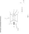
- Fig. 3 shows schematically from the side (direction of incidence is the same as viewing direction) a flat sheet of light LB, also called a light disk, which is produced for example with a cylindrical lens (O2-ZL) and passes through the sample (P).
- An objective O of a microscope for example a wide field microscope with a CCD camera, a laser scanning microscope or a microscope with structured illumination, is located above the sample.
- the light sheet LB in the form of the SPIM light sheet which is essentially exactly in the focal plane (F) of the objective O, is carried out in FIG Fig. 3 photoactivation perpendicular to the optical axis of fluorescence excitation and detection.
- the fluorescence excitation can only take place within the focal plane (F).
- the fluorescence excitation and the fluorescence detection take place according to WO2006 / 127692 via the microscope objective O. This results in a localized excitation in the z-direction and samples can be examined three-dimensionally without non-linear photoactivation using the PALM method.
- the width of the light beam for photoactivation ie its extension in the z-direction, is adapted so that it is advantageously smaller than or equal to the axial extension of the PSF given by the numerical aperture of the objective O. This advantageously prevents fluorescent molecules from being activated and bleached outside the focal plane.
- fluorescence can only come from this plane defined by the activation beam. Thus this arrangement is inherently 3D resolving. Detection takes place using conventional means, such as classic wide-field microscopy, confocal microscopy or structured lighting (ZEISS APOTOM).
- the excitation beam is able to excite autofluorescence over the entire sample space.
- the light beam to excite the fluorescence (after photoactivation) is radiated with a light sheet (LB) perpendicularly for detection via O2 - ZL.
- LB light sheet
- the fluorescent light can be detected particularly efficiently separately from the excitation light, since no spectral separation by means of a dichroic beam splitter is required.
- switchable dyes such as DENTRA
- photoactivation and fluorescence excitation take place with the same wavelength. This can be implemented particularly easily with this.
- the high-resolution image is recorded for the arrangements according to the invention as in FIG WO2006 / 127692 described with the above steps 1-4.
- Fluorescent proteins known from the prior art such as PA-GFP or DRONPA, are preferably used as activatable fluorescent dyes. Photoactivation takes place at 405 nm, fluorescence excitation at 488 nm and detection in the range above 490 nm.
- reversibly switchable synthetic dyes such as Alexa / Cyan constructs can also be used.
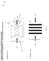
- a further arrangement according to the invention with illumination by means of two light sheets LB 1 and LB 2 is shown schematically.
- the interferometric superposition of light sheets from several directions creates an interference pattern along the drawn x-direction in the focal plane.
- the light sheets can in turn contain laser light for photoactivation and / or fluorescence excitation.
- the superposition creates a so-called standing wave field (SW), which is shown schematically in Fig. 4b shown as a striped pattern. If, for example, two light sheets are used for photoactivation, it can be achieved that the distance between the fluorescence emitters to be activated is greater than or equal to the width of the PSF of the detection (O in Fig.
- interference results in a strip-shaped activation localized in x and z.
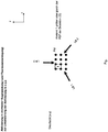
- light sheets LB 1 to LB 3 120 ° angle
- FIG Fig. 5 depicted a dot pattern PM, i.e. an activation localized in x, z and y, so that the distance (1) of the activated fluorescence emitters is greater than or equal to the width of the PSF of the detection (O in Fig. 4a ) is.
- the fluorescence excitation can preferably also take place via one or more light sheets, which in turn avoids extra-focal autofluorescence.
- the fluorescence excitation from direction O in Fig. 4a can also be structured in one or more directions and, for example, also have a hole pattern (structuring in x and y). This can ensure that the distance between the fluorescence emitters is greater than or equal to the width of the PSF of the detection.
- a structuring can be done, for example, with a grid structure ( DE 10257237A1 ) or with a multi-spot excitation ( DE102006017841 ) respectively.
- the photoactivation can take place via the objective O. and the fluorescence excitation can be realized with several light disk beams which form an interference pattern of the type described above. Molecules that have been activated with overlapping diffraction disks are thus excited to different degrees. This also prevents gaps in the camera image. Autofluorescence generated by the activation beam can be temporally and / or spectrally separated. After a plane has been recorded, it must be deactivated via the sample area for 3D recordings.
- the structured activation can also be implemented through a special image (e.g. a grid - as described above) or through a scanning mechanism.
- the light beam can, for example, scan the image field and its intensity is changed during the movement by, for example, a fast AOTF so that an activation pattern, for example, is corresponding Fig. 5 arises in the focal plane.
- an activation pattern for example, is corresponding Fig. 5 arises in the focal plane.
- molecules outside the focal plane are also activated.
- a lateral light sheet fluorescence excitation can ensure that only fluorescence from the focal plane is detected.
- it must be deactivated via the sample area for 3D recordings.
- the intensity of the activation beam should ideally be selected so that, on a statistical average, only one molecule per activation spot (corresponds to approximately PSF size) is excited. In this way, the probability is reduced that 2 molecules with overlapping diffraction disks are activated at the same time. In the course of the image acquisition, the activation pattern must of course be phase-shifted so that all molecules are activated evenly. Autofluorescence generated by the activation beam can be temporally and / or spectrally separated. The activation intensities are usually so small that autofluorescence should not play a role.
- the photoactivation and fluorescence excitation beams can be exchanged here. This has the advantage that no photo-activation takes place outside the focal plane.
- the activation can be unstructured via the light sheet and the excitation can be coordinated to the PSF and structured via the objective be performed. Molecules that were activated with overlapping diffraction disks are thus excited to different degrees. In this way, too, gaps in the camera image can be avoided.
- the problem of extra-focal autofluorescence does exist here.
- a problem with all the variants described is the axial resolution, which in the SPIM method is generally determined by the width of the light sheet used. Since the NA used to generate it is usually much smaller than the NA of the detection objective, the problem of a highly elongated system PSF (lateral expansion determined by the resolution of the PALM process (nanometer range), axial expansion) arises directly determined by the light sheet width (micrometer range). This causes disadvantages in 3D imaging. With the help of the multiview technology known from the prior art (recording of stacks from different angles) this problem can be avoided and an effective, largely homogeneous spatial resolution can be generated according to the lateral PALM resolution.
- the photo-activated molecules in the edge areas of the light sheet used for activation are deactivated again by a further structured light sheet in the sense of a non-linear interaction in order to achieve a higher z-resolution.
- a further structured light sheet in the sense of a non-linear interaction in order to achieve a higher z-resolution.
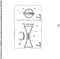
- a light sheet can also be used as the deactivation beam, but it is structured in such a way that it has a zero point in the focal plane over the area of the image area to be observed, as in FIG Fig. 6 shown.
- the pupil intensity distribution (I) of the light sheet beam corresponds here to a line that was previously generated by suitable optics (eg with a Powell lens).
- a phase plate (II) is introduced into the pupil, which has an area (III) over half of the line, which generates a pi phase jump.
- the light sheet (V) extended in the xy plane is generated by suitable optics (IV).
- suitable optics (IV) In the area of the depth of focus of the illumination optics (IV) there is a zero point plane (VI) parallel to the focal plane of the detection optics (VII), in which no molecules are de-excited. According to the STED-like method, this allows the axial Expansion of the light sheet with photo-activated molecules in a non-linear manner can be greatly restricted and the axial resolution can be improved.
- Fig. 7 shows a general optical embodiment for using the described advantageous methods and applications with photoactivation / deactivation via (x-direction structured) light sheet and CCD wide-field detection.
- the sample is marked with Dronpa, for example, and can be switched on (activated) above 405 nm and excited or switched off again at 488 nm.
- the lasers (1) are intended for 405 nm (photo-activation) and 488 nm (fluorescence excitation and photo-deactivation) and are combined via a beam combination (2) and dichroic mirrors.
- One and the same wavelength as explained above using the DENTRA example can also be used for photoactivation and fluorescence excitation. This means that a laser (405 nm in this case) and the beam combination (2) can be omitted.
- An AOTF (3) is used for wavelength selection and for rapid switching / attenuation of the laser wavelengths.
- a rotatable lambda / 2 plate (4) and a pole splitter (PBS) (5) with fiber coupling for 2 channels are arranged downstream of it in the direction of illumination.
- PBS pole splitter
- the light is transmitted to the sample (12) via the single-mode fibers (6) via cylinder optics (7) to generate a light sheet and imaging optics (8) via beam paths (10) or (11) for photoactivation (or also deactivation or excitation). irradiated.
- the optical path lengths are adjusted accordingly.
- the standing wave field is shifted in the focal plane to illuminate the sample in the intensity minima by setting the relative phase between the two light sheets, for example with a phase modulator (PH).
- the light generated in the sample (12) is detected via a detection objective (13) (microscope objective) in a detection beam path (14) via a tube lens (15) and emission filter (16) by means of a CCD camera.
- An optional (pivotable) color splitter (18) for reflecting a laser (22) or a wide-field light source (23) is shown in dashed lines in the detection beam path. shown if the fluorescence excitation occurs through the detection objective. You can optionally choose between laser and wide-field light source using a pivotable mirror (20).
- the laser (22) or the wide-field light source (23) can also be used for activation, in which case a wavelength of 405 nm must be provided instead of a wavelength of 488 nm when DRONPA is used as the dye.
- a scanner unit (21) is provided for the laser beam path (22), which allows a point-like scanning of the image field. Imaging optics (19) adapted for this purpose are provided between the scanner unit (21) and the color splitter (18).
- phase plates (9) can be introduced into the illumination beam paths.
Landscapes
- Physics & Mathematics (AREA)
- General Physics & Mathematics (AREA)
- Chemical & Material Sciences (AREA)
- Analytical Chemistry (AREA)
- Optics & Photonics (AREA)
- Health & Medical Sciences (AREA)
- Biochemistry (AREA)
- Life Sciences & Earth Sciences (AREA)
- Nuclear Medicine, Radiotherapy & Molecular Imaging (AREA)
- General Health & Medical Sciences (AREA)
- Immunology (AREA)
- Pathology (AREA)
- Engineering & Computer Science (AREA)
- Multimedia (AREA)
- Computer Vision & Pattern Recognition (AREA)
- Investigating, Analyzing Materials By Fluorescence Or Luminescence (AREA)
- Microscoopes, Condenser (AREA)
Applications Claiming Priority (2)
| Application Number | Priority Date | Filing Date | Title |
|---|---|---|---|
| DE102008009216A DE102008009216A1 (de) | 2008-02-13 | 2008-02-13 | Vorrichtung und Verfahren zum räumlich hochauflösenden Abbilden einer Struktur einer Probe |
| PCT/EP2009/000677 WO2009100830A1 (de) | 2008-02-13 | 2009-02-03 | Vorrichtung und verfahren zum räumlichen hochauflösenden abbilden einer struktur einer probe |
Publications (2)
| Publication Number | Publication Date |
|---|---|
| EP2245494A1 EP2245494A1 (de) | 2010-11-03 |
| EP2245494B1 true EP2245494B1 (de) | 2021-01-27 |
Family
ID=40635862
Family Applications (1)
| Application Number | Title | Priority Date | Filing Date |
|---|---|---|---|
| EP09709871.9A Active EP2245494B1 (de) | 2008-02-13 | 2009-02-03 | Vorrichtung und verfahren zum räumlichen hochauflösenden abbilden einer struktur einer probe |
Country Status (5)
| Country | Link |
|---|---|
| US (1) | US8362448B2 (enExample) |
| EP (1) | EP2245494B1 (enExample) |
| JP (2) | JP5826494B2 (enExample) |
| DE (1) | DE102008009216A1 (enExample) |
| WO (1) | WO2009100830A1 (enExample) |
Families Citing this family (71)
| Publication number | Priority date | Publication date | Assignee | Title |
|---|---|---|---|---|
| DE102008054317A1 (de) * | 2008-11-03 | 2010-05-06 | Carl Zeiss Microlmaging Gmbh | Kombinationsmikroskopie |
| DE102008059328A1 (de) | 2008-11-27 | 2010-06-02 | Carl Zeiss Microimaging Gmbh | Auflösungsgesteigerte Mikroskopie |
| WO2010125844A1 (ja) * | 2009-04-30 | 2010-11-04 | 国立大学法人大阪大学 | 変位測定装置及び変位測定方法 |
| DE102009031231A1 (de) * | 2009-06-26 | 2010-12-30 | Carl Zeiss Microlmaging Gmbh | Verfahren und Anordnungen für die Fluoreszenzmikroskopie |
| DE102009044984A1 (de) * | 2009-09-24 | 2011-03-31 | Carl Zeiss Microimaging Gmbh | Mikroskop |
| DE102009043747A1 (de) * | 2009-09-30 | 2011-03-31 | Carl Zeiss Microlmaging Gmbh | Verfahren zur Erzeugung eines Mikroskopbildes und Mikroskop |
| DE102010028138A1 (de) * | 2010-04-22 | 2011-10-27 | MAX-PLANCK-Gesellschaft zur Förderung der Wissenschaften e.V. | Bestimmen der Verteilung einer Substanz durch Abtasten mit einer Messfront |
| US10051240B2 (en) | 2010-06-14 | 2018-08-14 | Howard Hughes Medical Institute | Structured plane illumination microscopy |
| US8711211B2 (en) | 2010-06-14 | 2014-04-29 | Howard Hughes Medical Institute | Bessel beam plane illumination microscope |
| WO2012027542A2 (en) * | 2010-08-25 | 2012-03-01 | California Institute Of Technology | Simultaneous orthogonal light sheet microscopy and computed optical tomography |
| JP2013539074A (ja) | 2010-09-24 | 2013-10-17 | カール・ツァイス・マイクロスコピー・ゲゼルシャフト・ミット・ベシュレンクテル・ハフツング | 3d局在顕微鏡法並びに4d局在顕微鏡法及び追跡方法並びに追跡システム |
| DE102010041426A1 (de) * | 2010-09-27 | 2012-05-03 | Siemens Aktiengesellschaft | Messeinheit und Verfahren zur optischen Untersuchung einer Flüssigkeit zur Bestimmung einer Analyt-Konzentration |
| WO2012049831A1 (ja) * | 2010-10-14 | 2012-04-19 | 株式会社ニコン | 構造化照明装置、構造化照明顕微鏡装置、及び面形状測定装置 |
| DE102010060121C5 (de) * | 2010-10-22 | 2023-09-28 | Leica Microsystems Cms Gmbh | SPIM-Mikroskop mit sequenziellem Lightsheet |
| DE102010044013A1 (de) * | 2010-11-16 | 2012-05-16 | Carl Zeiss Microimaging Gmbh | Tiefenauflösungsgesteigerte Mikroskopie |
| US10908403B2 (en) * | 2011-02-14 | 2021-02-02 | European Molecular Biology Laboratory (Embl) | Light-pad microscope for high-resolution 3D fluorescence imaging and 2D fluctuation spectroscopy |
| DE102011017078B4 (de) * | 2011-04-15 | 2019-01-31 | Leica Microsystems Cms Gmbh | Weitfeld-Mikroskop-Beleuchtungssystem, Verwendung desselben und Weitfeld-Beleuchtungsverfahren |
| DE102011007751B4 (de) * | 2011-04-20 | 2023-10-19 | Carl Zeiss Microscopy Gmbh | Weitfeldmikroskop und Verfahren zur Weitfeldmikroskopie |
| DE102012201003B4 (de) * | 2012-01-24 | 2024-07-25 | Carl Zeiss Microscopy Gmbh | Mikroskop und Verfahren für die hochauflösende 3-D Fluoreszenzmikroskopie |
| DE102012211943A1 (de) | 2012-07-09 | 2014-06-12 | Carl Zeiss Microscopy Gmbh | Mikroskop |
| DE102012214568A1 (de) * | 2012-08-16 | 2014-02-20 | Leica Microsystems Cms Gmbh | Optische Anordnung und ein Mikroskop |
| EP2898312B1 (en) * | 2012-09-24 | 2021-03-24 | Global Life Sciences Solutions USA LLC | Methods for resolving positions in fluorescence stochastic microscopy using three-dimensional structured illumination. |
| US9404869B2 (en) | 2012-10-09 | 2016-08-02 | Howard Hughes Medical Institute | Multiview light-sheet microscopy |
| DE102013213781A1 (de) * | 2013-03-20 | 2014-09-25 | Leica Microsystems Cms Gmbh | Verfahren und optische Anordnung zum Manipulieren und Abbilden einer mikroskopischen Probe |
| WO2014147211A1 (en) * | 2013-03-21 | 2014-09-25 | ETH Zürich | Method and device to achieve spatially confined photointeraction at the focal volume of a microscope |
| EP2801854B1 (en) | 2013-05-10 | 2017-07-19 | Ruprecht-Karls-Universität Heidelberg | Method and apparatus for combination of localization microscopy and structured illumination microscopy |
| DE102013208926A1 (de) * | 2013-05-14 | 2014-11-20 | Carl Zeiss Microscopy Gmbh | Verfahren zur 3D-hochauflösenden Lokalisierungsmikroskopie |
| DE102013009042A1 (de) | 2013-05-28 | 2014-12-04 | Carl Zeiss Microscopy Gmbh | Lumineszenzmikroskopie |
| DE102013216124A1 (de) * | 2013-08-14 | 2015-02-19 | Carl Zeiss Microscopy Gmbh | Hochauflösende 3D-Fluoreszenzmikroskopie |
| US10539772B2 (en) * | 2013-10-09 | 2020-01-21 | Howard Hughes Medical Institute | Multiview light-sheet microscopy |
| GB201318598D0 (en) * | 2013-10-21 | 2013-12-04 | Univ Leicester | Improvements in or relating to super-resolution microscopy |
| DE102013226277A1 (de) * | 2013-12-17 | 2015-06-18 | Leica Microsystems Cms Gmbh | Verfahren und Vorrichtung zum Untersuchen einer Probe mittels optischer Projektionstomografie |
| DE102013114860B3 (de) | 2013-12-23 | 2015-05-28 | MAX-PLANCK-Gesellschaft zur Förderung der Wissenschaften e.V. | Verfahren und Vorrichtung zur Bestimmung der Orte einzelner Moleküle einer Substanz in einer Probe |
| DE112015001154T5 (de) * | 2014-04-24 | 2016-12-08 | Olympus Corporation | Mikroskop und Mikroskopie-Verfahren |
| JP6439089B2 (ja) * | 2014-05-15 | 2018-12-19 | キヤノン株式会社 | 光学系およびそれを備えた内視鏡装置 |
| WO2016054118A1 (en) * | 2014-09-29 | 2016-04-07 | Howard Hughes Medical Institute | Non-linear structured illumination microscopy |
| US10795144B2 (en) | 2014-12-06 | 2020-10-06 | Howard Hughes Medical Institute | Microscopy with structured plane illumination and point accumulation for imaging and nanoscale topography |
| US9921161B1 (en) * | 2015-01-08 | 2018-03-20 | Daniel Feldkhun | Structured light active localization microscopy |
| JP6635052B2 (ja) * | 2015-02-05 | 2020-01-22 | 株式会社ニコン | 構造化照明顕微鏡、及び観察方法 |
| DE102015103802A1 (de) * | 2015-03-16 | 2016-09-22 | Carl Zeiss Microscopy Gmbh | Verfahren und Anordnung zur lichtblattmikroskopischen Untersuchung einer Probe |
| DE102016104651A1 (de) | 2015-03-24 | 2016-09-29 | Abberior Instruments Gmbh | Verfahren und Rasterfluoreszenzlichtmikroskop zum dreidimensional hochauflösenden Abbilden einer mit Fluorophoren markierten Struktur einer Probe |
| US10989661B2 (en) * | 2015-05-01 | 2021-04-27 | The Board Of Regents Of The University Of Texas System | Uniform and scalable light-sheets generated by extended focusing |
| JP6552881B2 (ja) * | 2015-06-12 | 2019-07-31 | オリンパス株式会社 | 顕微鏡および顕微鏡画像取得方法 |
| JP6594437B2 (ja) | 2015-09-15 | 2019-10-23 | オリンパス株式会社 | 顕微鏡および顕微鏡観察方法 |
| CN108292034B (zh) * | 2015-10-09 | 2022-01-04 | 徕卡显微系统复合显微镜有限公司 | 用于利用结构化的光片照射检查试样的方法和设备 |
| US10876970B2 (en) | 2016-04-12 | 2020-12-29 | The Board Of Regents Of The University Of Texas System | Light-sheet microscope with parallelized 3D image acquisition |
| US11067781B2 (en) | 2016-05-03 | 2021-07-20 | Leica Microsystems Cms Gmbh | Microscope and method for localizing fluorescent molecules in three spatial dimensions |
| JP2017203822A (ja) * | 2016-05-09 | 2017-11-16 | オリンパス株式会社 | 照明設定方法、シート照明顕微鏡装置、及びプログラム |
| US11320640B2 (en) | 2016-06-24 | 2022-05-03 | Howard Hughes Medical Institute | Automated adjustment of light sheet geometry in a microscope |
| JP2018004777A (ja) * | 2016-06-28 | 2018-01-11 | オリンパス株式会社 | 光シート顕微鏡、及び、光シート顕微鏡の制御方法 |
| LU93143B1 (de) | 2016-07-06 | 2018-03-05 | Leica Microsystems | Verfahren zum Untersuchen einer Probe sowie Vorrichtung zum Ausführen eines solchen Verfahrens |
| EP3497502B1 (de) | 2016-08-15 | 2022-10-26 | Leica Microsystems CMS GmbH | Lichtblattmikroskop |
| US11506877B2 (en) | 2016-11-10 | 2022-11-22 | The Trustees Of Columbia University In The City Of New York | Imaging instrument having objective axis and light sheet or light beam projector axis intersecting at less than 90 degrees |
| SG11201909327QA (en) | 2017-04-07 | 2019-11-28 | Univ I Tromsoe Norges Arktiske Univ | Optical component for generating a periodic light pattern |
| US11415528B2 (en) * | 2017-10-10 | 2022-08-16 | Wdi Wise Device Inc. | Method and apparatus for automated in-line inspection of optically transparent materials |
| AU2019205496B2 (en) | 2018-01-08 | 2021-08-19 | Illumina, Inc. | High-throughput sequencing with semiconductor-based detection |
| NL2020621B1 (en) | 2018-01-08 | 2019-07-15 | Illumina Inc | Multiplexing of an active sensor detector using structured illumination |
| TWI725875B (zh) | 2018-01-16 | 2021-04-21 | 美商伊路米納有限公司 | 結構照明成像系統和使用結構化光來創建高解析度圖像的方法 |
| NL2020619B1 (en) | 2018-01-16 | 2019-07-25 | Illumina Inc | Dual optical grating slide structured illumination imaging |
| NL2020620B1 (en) | 2018-01-16 | 2019-07-25 | Illumina Inc | Pattern angle spatial selection structured illumination imaging |
| NL2020623B1 (en) | 2018-01-24 | 2019-07-30 | Illumina Inc | Structured illumination microscopy with line scanning |
| NL2020622B1 (en) | 2018-01-24 | 2019-07-30 | Lllumina Cambridge Ltd | Reduced dimensionality structured illumination microscopy with patterned arrays of nanowells |
| NL2021258B1 (en) | 2018-06-14 | 2019-12-20 | Illumina Inc | Device for luminescent imaging |
| TWI718557B (zh) | 2018-06-29 | 2021-02-11 | 美商伊路米納有限公司 | 用於預測結構照明參數之方法、系統和非暫時性電腦可讀取媒體 |
| CN109143562B (zh) * | 2018-09-12 | 2020-12-15 | 苏州大学 | 一种基于变焦原理的可变光片照明系统 |
| DE102018215831B4 (de) * | 2018-09-18 | 2020-04-02 | Fraunhofer-Gesellschaft zur Förderung der angewandten Forschung e.V. | Optische Anordnung für fluoreszenzmikroskopische Anwendungen |
| US10901202B2 (en) | 2018-09-19 | 2021-01-26 | Illumina, Inc. | Structured illumination of a sample |
| MX2022004774A (es) * | 2019-10-21 | 2022-05-16 | Illumina Inc | Eficiencia aumentada de calculo para microscopia de iluminacion estructurada. |
| DE102019008989B3 (de) * | 2019-12-21 | 2021-06-24 | Abberior Instruments Gmbh | Verfahren zur Störungskorrektur und Laserscanningmikroskop mit Störungskorrektur |
| GB2596145A (en) * | 2020-06-19 | 2021-12-22 | Oxford Nanoimaging Ltd | A optical imaging method |
| DE102020130476A1 (de) * | 2020-11-18 | 2022-05-19 | MAX-PLANCK-Gesellschaft zur Förderung der Wissenschaften e.V. | Verfahren und Laserscanningmikroskop zum Abbilden einer mit verschiedenen Fluoreszenzmarkern markierten Struktur einer Probe |
Citations (1)
| Publication number | Priority date | Publication date | Assignee | Title |
|---|---|---|---|---|
| WO2009043473A1 (de) * | 2007-09-28 | 2009-04-09 | Carl Zeiss Microimaging Gmbh | Optische anordnung zur photomanipulation |
Family Cites Families (13)
| Publication number | Priority date | Publication date | Assignee | Title |
|---|---|---|---|---|
| US6309886B1 (en) * | 1999-06-04 | 2001-10-30 | The Regents Of The University Of California | High throughput analysis of samples in flowing liquid |
| US6888148B2 (en) | 2001-12-10 | 2005-05-03 | Carl Zeiss Jena Gmbh | Arrangement for the optical capture of excited and /or back scattered light beam in a sample |
| JPWO2004036284A1 (ja) * | 2002-09-30 | 2006-02-16 | 独立行政法人科学技術振興機構 | 共焦点顕微鏡、共焦点顕微鏡を用いた蛍光測定方法及び偏光測定方法 |
| DE10254139A1 (de) * | 2002-11-15 | 2004-05-27 | Carl Zeiss Jena Gmbh | Verfahren und Anordnung zur tiefenaufgelösten optischen Erfassung einer Probe |
| DE10257423A1 (de) | 2002-12-09 | 2004-06-24 | Europäisches Laboratorium für Molekularbiologie (EMBL) | Mikroskop |
| EP1581625A2 (en) | 2002-12-11 | 2005-10-05 | Eli Lilly And Company | Junctional adhesion molecule splice variants |
| JP2005321347A (ja) * | 2004-05-11 | 2005-11-17 | Hitachi High-Technologies Corp | 光検出装置 |
| DE102004034957A1 (de) * | 2004-07-16 | 2006-02-02 | Carl Zeiss Jena Gmbh | Anordnung zur mikroskopischen Beobachtung und/oder Detektion und Verwendung |
| EP3203235A1 (en) | 2005-05-23 | 2017-08-09 | Harald F. Hess | Optical microscopy with phototransformable optical labels |
| US7485875B2 (en) * | 2005-07-22 | 2009-02-03 | Carl Zeiss Microimaging Gmbh | Resolution-enhanced luminescence microscopy |
| DE102006017841A1 (de) | 2006-04-18 | 2007-10-25 | Carl Zeiss Microimaging Gmbh | Laser-Scanning-Mikroskop mit Hauptstrahlteiler zur räumlichen Trennung von Beleuchtungs- und Detektionsstrahlung |
| JP2007114542A (ja) * | 2005-10-21 | 2007-05-10 | Olympus Corp | 顕微鏡観察装置および顕微鏡観察方法 |
| WO2007135804A1 (ja) * | 2006-05-22 | 2007-11-29 | Tokyo Institute Of Technology | レーザ誘起蛍光法を用いた流体計測装置及び流体計測方法 |
-
2008
- 2008-02-13 DE DE102008009216A patent/DE102008009216A1/de not_active Ceased
-
2009
- 2009-02-03 US US12/867,291 patent/US8362448B2/en active Active
- 2009-02-03 WO PCT/EP2009/000677 patent/WO2009100830A1/de not_active Ceased
- 2009-02-03 JP JP2010546236A patent/JP5826494B2/ja active Active
- 2009-02-03 EP EP09709871.9A patent/EP2245494B1/de active Active
-
2015
- 2015-07-10 JP JP2015138556A patent/JP6039760B2/ja active Active
Patent Citations (1)
| Publication number | Priority date | Publication date | Assignee | Title |
|---|---|---|---|---|
| WO2009043473A1 (de) * | 2007-09-28 | 2009-04-09 | Carl Zeiss Microimaging Gmbh | Optische anordnung zur photomanipulation |
Also Published As
| Publication number | Publication date |
|---|---|
| JP5826494B2 (ja) | 2015-12-02 |
| JP2015215629A (ja) | 2015-12-03 |
| WO2009100830A1 (de) | 2009-08-20 |
| DE102008009216A1 (de) | 2009-08-20 |
| US20110036996A1 (en) | 2011-02-17 |
| EP2245494A1 (de) | 2010-11-03 |
| JP2011511966A (ja) | 2011-04-14 |
| US8362448B2 (en) | 2013-01-29 |
| JP6039760B2 (ja) | 2016-12-07 |
Similar Documents
| Publication | Publication Date | Title |
|---|---|---|
| EP2245494B1 (de) | Vorrichtung und verfahren zum räumlichen hochauflösenden abbilden einer struktur einer probe | |
| EP2516993B1 (de) | Hochauflösendes mikroskop und verfahren zur zwei- oder dreidimensionalen positionsbestimmung von objekten | |
| EP2102695B1 (de) | Verfahren und anordnung zur parallelisierten mikroskopischen bildgebung | |
| EP2641078B1 (de) | Tiefenauflösungsgesteigerte mikroskopie | |
| EP2317362B1 (de) | Mikroskopisches Verfahren und Mikroskop mit gesteigerter Auflösung | |
| EP2097781B1 (de) | Lasermikroskop mit räumlich trennendem strahlteiler | |
| EP2860566B1 (de) | Hochauflösende Scanning-Mikroskopie | |
| EP2069761B1 (de) | Verfahren und vorrichtung zum hochaufgelösten optischen abtasten einer probe | |
| EP1248132B1 (de) | Verfahren und Anordnung zur tiefenaufgelösten optischen Erfassung einer Probe | |
| EP2185919A1 (de) | Sted-fluoreszenzmikroskopie mit zweiphotonen-anregung | |
| WO2005024482A1 (de) | Lichtquelle mit einem mikrostrukturierten optischen element | |
| DE102009043744A1 (de) | Verfahren und Mikroskop zur dreidimensional auflösungsgesteigerten Mikroskopie | |
| DE102011077269A1 (de) | Hochauflösende Lumineszenzmikroskopie | |
| DE102016102286A1 (de) | Vorrichtung und Verfahren zur Multispot-Scanning-Mikroskopie | |
| DE10139754B4 (de) | Beleuchtungsverfahren für ein Scanmikroskop und Scanmikroskop | |
| WO2017060506A1 (de) | Verfahren und vorrichtung zum untersuchen einer probe mit einer strukturiereten lichtblattbeleuchtung | |
| DE102006009831B4 (de) | Verfahren und Mikroskop zur räumlich hochauflösenden Untersuchung von Proben | |
| DE102013022026A1 (de) | Mehrfarben-Scanning-Mikroskop | |
| DE102005009188A1 (de) | Punktscannendes Laser-Scanning-Mikroskop sowie Verfahren zur Einstellung eines Mikroskopes | |
| WO2017220668A1 (de) | Mikroskopieverfahren unter nutzung zeitlicher fokusmodulation und mikroskop | |
| DE102016104651A1 (de) | Verfahren und Rasterfluoreszenzlichtmikroskop zum dreidimensional hochauflösenden Abbilden einer mit Fluorophoren markierten Struktur einer Probe | |
| DE10201388A1 (de) | Verfahren und / oder Apparaturen für mikroskopische Abbildung | |
| WO2003060610A1 (de) | Verfahren und anordnungen zur mikroskopischen abbildung | |
| WO2020058074A1 (de) | Optische anordnung für fluoreszenzmikroskopische anwendungen |
Legal Events
| Date | Code | Title | Description |
|---|---|---|---|
| PUAI | Public reference made under article 153(3) epc to a published international application that has entered the european phase |
Free format text: ORIGINAL CODE: 0009012 |
|
| 17P | Request for examination filed |
Effective date: 20100911 |
|
| AK | Designated contracting states |
Kind code of ref document: A1 Designated state(s): AT BE BG CH CY CZ DE DK EE ES FI FR GB GR HR HU IE IS IT LI LT LU LV MC MK MT NL NO PL PT RO SE SI SK TR |
|
| AX | Request for extension of the european patent |
Extension state: AL BA RS |
|
| DAX | Request for extension of the european patent (deleted) | ||
| APBK | Appeal reference recorded |
Free format text: ORIGINAL CODE: EPIDOSNREFNE |
|
| APAF | Appeal reference modified |
Free format text: ORIGINAL CODE: EPIDOSCREFNE |
|
| RAP1 | Party data changed (applicant data changed or rights of an application transferred) |
Owner name: CARL ZEISS MICROSCOPY GMBH |
|
| TPAC | Observations filed by third parties |
Free format text: ORIGINAL CODE: EPIDOSNTIPA |
|
| STAA | Information on the status of an ep patent application or granted ep patent |
Free format text: STATUS: EXAMINATION IS IN PROGRESS |
|
| 17Q | First examination report despatched |
Effective date: 20161206 |
|
| RIC1 | Information provided on ipc code assigned before grant |
Ipc: G01N 21/64 20060101ALI20200701BHEP Ipc: G02B 21/00 20060101AFI20200701BHEP Ipc: G02B 21/10 20060101ALI20200701BHEP Ipc: G02B 27/58 20060101ALI20200701BHEP Ipc: G02B 21/36 20060101ALI20200701BHEP |
|
| GRAP | Despatch of communication of intention to grant a patent |
Free format text: ORIGINAL CODE: EPIDOSNIGR1 |
|
| STAA | Information on the status of an ep patent application or granted ep patent |
Free format text: STATUS: GRANT OF PATENT IS INTENDED |
|
| INTG | Intention to grant announced |
Effective date: 20200812 |
|
| GRAS | Grant fee paid |
Free format text: ORIGINAL CODE: EPIDOSNIGR3 |
|
| GRAA | (expected) grant |
Free format text: ORIGINAL CODE: 0009210 |
|
| STAA | Information on the status of an ep patent application or granted ep patent |
Free format text: STATUS: THE PATENT HAS BEEN GRANTED |
|
| RIN1 | Information on inventor provided before grant (corrected) |
Inventor name: POWER, CHRISTOPHER Inventor name: WOLLESCHENSKY, RALF Inventor name: RADT, BENNO Inventor name: LIPPERT, HELMUT |
|
| AK | Designated contracting states |
Kind code of ref document: B1 Designated state(s): AT BE BG CH CY CZ DE DK EE ES FI FR GB GR HR HU IE IS IT LI LT LU LV MC MK MT NL NO PL PT RO SE SI SK TR |
|
| REG | Reference to a national code |
Ref country code: GB Ref legal event code: FG4D Free format text: NOT ENGLISH |
|
| REG | Reference to a national code |
Ref country code: CH Ref legal event code: EP |
|
| REG | Reference to a national code |
Ref country code: AT Ref legal event code: REF Ref document number: 1360175 Country of ref document: AT Kind code of ref document: T Effective date: 20210215 |
|
| REG | Reference to a national code |
Ref country code: IE Ref legal event code: FG4D Free format text: LANGUAGE OF EP DOCUMENT: GERMAN |
|
| REG | Reference to a national code |
Ref country code: DE Ref legal event code: R096 Ref document number: 502009016320 Country of ref document: DE |
|
| REG | Reference to a national code |
Ref country code: NL Ref legal event code: MP Effective date: 20210127 |
|
| REG | Reference to a national code |
Ref country code: LT Ref legal event code: MG9D |
|
| PG25 | Lapsed in a contracting state [announced via postgrant information from national office to epo] |
Ref country code: HR Free format text: LAPSE BECAUSE OF FAILURE TO SUBMIT A TRANSLATION OF THE DESCRIPTION OR TO PAY THE FEE WITHIN THE PRESCRIBED TIME-LIMIT Effective date: 20210127 Ref country code: GR Free format text: LAPSE BECAUSE OF FAILURE TO SUBMIT A TRANSLATION OF THE DESCRIPTION OR TO PAY THE FEE WITHIN THE PRESCRIBED TIME-LIMIT Effective date: 20210428 Ref country code: FI Free format text: LAPSE BECAUSE OF FAILURE TO SUBMIT A TRANSLATION OF THE DESCRIPTION OR TO PAY THE FEE WITHIN THE PRESCRIBED TIME-LIMIT Effective date: 20210127 Ref country code: LT Free format text: LAPSE BECAUSE OF FAILURE TO SUBMIT A TRANSLATION OF THE DESCRIPTION OR TO PAY THE FEE WITHIN THE PRESCRIBED TIME-LIMIT Effective date: 20210127 Ref country code: PT Free format text: LAPSE BECAUSE OF FAILURE TO SUBMIT A TRANSLATION OF THE DESCRIPTION OR TO PAY THE FEE WITHIN THE PRESCRIBED TIME-LIMIT Effective date: 20210527 Ref country code: BG Free format text: LAPSE BECAUSE OF FAILURE TO SUBMIT A TRANSLATION OF THE DESCRIPTION OR TO PAY THE FEE WITHIN THE PRESCRIBED TIME-LIMIT Effective date: 20210427 Ref country code: NO Free format text: LAPSE BECAUSE OF FAILURE TO SUBMIT A TRANSLATION OF THE DESCRIPTION OR TO PAY THE FEE WITHIN THE PRESCRIBED TIME-LIMIT Effective date: 20210427 Ref country code: NL Free format text: LAPSE BECAUSE OF FAILURE TO SUBMIT A TRANSLATION OF THE DESCRIPTION OR TO PAY THE FEE WITHIN THE PRESCRIBED TIME-LIMIT Effective date: 20210127 |
|
| PG25 | Lapsed in a contracting state [announced via postgrant information from national office to epo] |
Ref country code: SE Free format text: LAPSE BECAUSE OF FAILURE TO SUBMIT A TRANSLATION OF THE DESCRIPTION OR TO PAY THE FEE WITHIN THE PRESCRIBED TIME-LIMIT Effective date: 20210127 Ref country code: PL Free format text: LAPSE BECAUSE OF FAILURE TO SUBMIT A TRANSLATION OF THE DESCRIPTION OR TO PAY THE FEE WITHIN THE PRESCRIBED TIME-LIMIT Effective date: 20210127 Ref country code: LV Free format text: LAPSE BECAUSE OF FAILURE TO SUBMIT A TRANSLATION OF THE DESCRIPTION OR TO PAY THE FEE WITHIN THE PRESCRIBED TIME-LIMIT Effective date: 20210127 |
|
| PG25 | Lapsed in a contracting state [announced via postgrant information from national office to epo] |
Ref country code: IS Free format text: LAPSE BECAUSE OF FAILURE TO SUBMIT A TRANSLATION OF THE DESCRIPTION OR TO PAY THE FEE WITHIN THE PRESCRIBED TIME-LIMIT Effective date: 20210527 |
|
| REG | Reference to a national code |
Ref country code: BE Ref legal event code: MM Effective date: 20210228 |
|
| REG | Reference to a national code |
Ref country code: DE Ref legal event code: R097 Ref document number: 502009016320 Country of ref document: DE |
|
| PG25 | Lapsed in a contracting state [announced via postgrant information from national office to epo] |
Ref country code: CH Free format text: LAPSE BECAUSE OF NON-PAYMENT OF DUE FEES Effective date: 20210228 Ref country code: EE Free format text: LAPSE BECAUSE OF FAILURE TO SUBMIT A TRANSLATION OF THE DESCRIPTION OR TO PAY THE FEE WITHIN THE PRESCRIBED TIME-LIMIT Effective date: 20210127 Ref country code: CZ Free format text: LAPSE BECAUSE OF FAILURE TO SUBMIT A TRANSLATION OF THE DESCRIPTION OR TO PAY THE FEE WITHIN THE PRESCRIBED TIME-LIMIT Effective date: 20210127 Ref country code: LI Free format text: LAPSE BECAUSE OF NON-PAYMENT OF DUE FEES Effective date: 20210228 Ref country code: LU Free format text: LAPSE BECAUSE OF NON-PAYMENT OF DUE FEES Effective date: 20210203 Ref country code: MC Free format text: LAPSE BECAUSE OF FAILURE TO SUBMIT A TRANSLATION OF THE DESCRIPTION OR TO PAY THE FEE WITHIN THE PRESCRIBED TIME-LIMIT Effective date: 20210127 |
|
| PG25 | Lapsed in a contracting state [announced via postgrant information from national office to epo] |
Ref country code: SK Free format text: LAPSE BECAUSE OF FAILURE TO SUBMIT A TRANSLATION OF THE DESCRIPTION OR TO PAY THE FEE WITHIN THE PRESCRIBED TIME-LIMIT Effective date: 20210127 Ref country code: ES Free format text: LAPSE BECAUSE OF FAILURE TO SUBMIT A TRANSLATION OF THE DESCRIPTION OR TO PAY THE FEE WITHIN THE PRESCRIBED TIME-LIMIT Effective date: 20210127 Ref country code: DK Free format text: LAPSE BECAUSE OF FAILURE TO SUBMIT A TRANSLATION OF THE DESCRIPTION OR TO PAY THE FEE WITHIN THE PRESCRIBED TIME-LIMIT Effective date: 20210127 Ref country code: RO Free format text: LAPSE BECAUSE OF FAILURE TO SUBMIT A TRANSLATION OF THE DESCRIPTION OR TO PAY THE FEE WITHIN THE PRESCRIBED TIME-LIMIT Effective date: 20210127 |
|
| PLBE | No opposition filed within time limit |
Free format text: ORIGINAL CODE: 0009261 |
|
| STAA | Information on the status of an ep patent application or granted ep patent |
Free format text: STATUS: NO OPPOSITION FILED WITHIN TIME LIMIT |
|
| 26N | No opposition filed |
Effective date: 20211028 |
|
| PG25 | Lapsed in a contracting state [announced via postgrant information from national office to epo] |
Ref country code: IE Free format text: LAPSE BECAUSE OF NON-PAYMENT OF DUE FEES Effective date: 20210203 |
|
| PG25 | Lapsed in a contracting state [announced via postgrant information from national office to epo] |
Ref country code: SI Free format text: LAPSE BECAUSE OF FAILURE TO SUBMIT A TRANSLATION OF THE DESCRIPTION OR TO PAY THE FEE WITHIN THE PRESCRIBED TIME-LIMIT Effective date: 20210127 |
|
| REG | Reference to a national code |
Ref country code: AT Ref legal event code: MM01 Ref document number: 1360175 Country of ref document: AT Kind code of ref document: T Effective date: 20210203 |
|
| PG25 | Lapsed in a contracting state [announced via postgrant information from national office to epo] |
Ref country code: IT Free format text: LAPSE BECAUSE OF FAILURE TO SUBMIT A TRANSLATION OF THE DESCRIPTION OR TO PAY THE FEE WITHIN THE PRESCRIBED TIME-LIMIT Effective date: 20210127 Ref country code: AT Free format text: LAPSE BECAUSE OF NON-PAYMENT OF DUE FEES Effective date: 20210203 |
|
| PG25 | Lapsed in a contracting state [announced via postgrant information from national office to epo] |
Ref country code: IS Free format text: LAPSE BECAUSE OF FAILURE TO SUBMIT A TRANSLATION OF THE DESCRIPTION OR TO PAY THE FEE WITHIN THE PRESCRIBED TIME-LIMIT Effective date: 20210527 |
|
| PG25 | Lapsed in a contracting state [announced via postgrant information from national office to epo] |
Ref country code: BE Free format text: LAPSE BECAUSE OF NON-PAYMENT OF DUE FEES Effective date: 20210228 |
|
| PG25 | Lapsed in a contracting state [announced via postgrant information from national office to epo] |
Ref country code: HU Free format text: LAPSE BECAUSE OF FAILURE TO SUBMIT A TRANSLATION OF THE DESCRIPTION OR TO PAY THE FEE WITHIN THE PRESCRIBED TIME-LIMIT; INVALID AB INITIO Effective date: 20090203 Ref country code: CY Free format text: LAPSE BECAUSE OF FAILURE TO SUBMIT A TRANSLATION OF THE DESCRIPTION OR TO PAY THE FEE WITHIN THE PRESCRIBED TIME-LIMIT Effective date: 20210127 |
|
| PG25 | Lapsed in a contracting state [announced via postgrant information from national office to epo] |
Ref country code: MK Free format text: LAPSE BECAUSE OF FAILURE TO SUBMIT A TRANSLATION OF THE DESCRIPTION OR TO PAY THE FEE WITHIN THE PRESCRIBED TIME-LIMIT Effective date: 20210127 |
|
| PGFP | Annual fee paid to national office [announced via postgrant information from national office to epo] |
Ref country code: GB Payment date: 20240219 Year of fee payment: 16 |
|
| PGFP | Annual fee paid to national office [announced via postgrant information from national office to epo] |
Ref country code: FR Payment date: 20240221 Year of fee payment: 16 |
|
| PG25 | Lapsed in a contracting state [announced via postgrant information from national office to epo] |
Ref country code: MT Free format text: LAPSE BECAUSE OF FAILURE TO SUBMIT A TRANSLATION OF THE DESCRIPTION OR TO PAY THE FEE WITHIN THE PRESCRIBED TIME-LIMIT Effective date: 20210127 |
|
| PGFP | Annual fee paid to national office [announced via postgrant information from national office to epo] |
Ref country code: DE Payment date: 20250218 Year of fee payment: 17 |
|
| GBPC | Gb: european patent ceased through non-payment of renewal fee |
Effective date: 20250203 |
|
| PG25 | Lapsed in a contracting state [announced via postgrant information from national office to epo] |
Ref country code: TR Free format text: LAPSE BECAUSE OF FAILURE TO SUBMIT A TRANSLATION OF THE DESCRIPTION OR TO PAY THE FEE WITHIN THE PRESCRIBED TIME-LIMIT Effective date: 20210127 |