EP2243979A2 - Amortisseur d'oscillations réglable doté d'une soupape de fonctionnement d'urgence - Google Patents
Amortisseur d'oscillations réglable doté d'une soupape de fonctionnement d'urgence Download PDFInfo
- Publication number
- EP2243979A2 EP2243979A2 EP10160118A EP10160118A EP2243979A2 EP 2243979 A2 EP2243979 A2 EP 2243979A2 EP 10160118 A EP10160118 A EP 10160118A EP 10160118 A EP10160118 A EP 10160118A EP 2243979 A2 EP2243979 A2 EP 2243979A2
- Authority
- EP
- European Patent Office
- Prior art keywords
- valve
- damping
- emergency
- damping valve
- housing insert
- Prior art date
- Legal status (The legal status is an assumption and is not a legal conclusion. Google has not performed a legal analysis and makes no representation as to the accuracy of the status listed.)
- Granted
Links
Images


Classifications
-
- F—MECHANICAL ENGINEERING; LIGHTING; HEATING; WEAPONS; BLASTING
- F16—ENGINEERING ELEMENTS AND UNITS; GENERAL MEASURES FOR PRODUCING AND MAINTAINING EFFECTIVE FUNCTIONING OF MACHINES OR INSTALLATIONS; THERMAL INSULATION IN GENERAL
- F16F—SPRINGS; SHOCK-ABSORBERS; MEANS FOR DAMPING VIBRATION
- F16F9/00—Springs, vibration-dampers, shock-absorbers, or similarly-constructed movement-dampers using a fluid or the equivalent as damping medium
- F16F9/32—Details
- F16F9/44—Means on or in the damper for manual or non-automatic adjustment; such means combined with temperature correction
- F16F9/46—Means on or in the damper for manual or non-automatic adjustment; such means combined with temperature correction allowing control from a distance, i.e. location of means for control input being remote from site of valves, e.g. on damper external wall
- F16F9/464—Control of valve bias or pre-stress, e.g. electromagnetically
-
- F—MECHANICAL ENGINEERING; LIGHTING; HEATING; WEAPONS; BLASTING
- F16—ENGINEERING ELEMENTS AND UNITS; GENERAL MEASURES FOR PRODUCING AND MAINTAINING EFFECTIVE FUNCTIONING OF MACHINES OR INSTALLATIONS; THERMAL INSULATION IN GENERAL
- F16F—SPRINGS; SHOCK-ABSORBERS; MEANS FOR DAMPING VIBRATION
- F16F2230/00—Purpose; Design features
- F16F2230/24—Detecting or preventing malfunction, e.g. fail safe
Definitions
- the invention relates to an adjustable vibration damper according to the preamble of patent claim 1.
- the emergency operating valve comprises a passage, the outlet opening of which is at least partially covered by a valve body.
- a valve body In the execution after Fig. 2 of the DE 39 17 064 A1 the emergency operating valve comprises a passage, the outlet opening of which is at least partially covered by a valve body.
- Fig. 2 it is obvious that this is a Schematic representation is because there are no division joints, the z. B. require the installation of the valve disc 105 of the emergency valve.
- the object is achieved in that the emergency operation valve, a second emergency operation valve is connected in parallel, which has a deviating from the first emergency operation valve opening characteristic.
- the great advantage is that the parallel connection of at least two emergency operation valves, a curved Dämpfkraftkennline for emergency operation is achieved. At each intersection of two Dämpfventilkennlinien there is a transition point at which the slope of the Dämpfkraftkennline changes significantly, so that even degressive Dämpfkraftkennlinien can be realized.
- the damping valve has a valve housing insert, in which a damping valve body controlled at least indirectly by the actuator is arranged, wherein the valve housing insert has a plurality of emergency operating channels which are equipped with emergency operating valves.
- the valve housing insert has the advantage that the emergency operation valves are easily accessible and therefore easy to install.
- the emergency operation channels in the valve housing insert are designed as radial channels, so that the valve housing insert can be mounted anywhere in the circumferential direction in an outer Dämpfventilgephaseuse.
- the radial channels are connected to a collecting space, which in turn is connected to the discharge opening of the damping valve.
- the emergency operating valve has a housing in which a valve element is arranged, which is biased by a arranged inside the housing closing spring in a closed position, wherein the closing spring is adjustable in its closing force.
- the housing of the emergency operation valve is screwed into the valve housing insert.
- the emergency operation valve comprises a Dämpfventilaufsatz, which is arranged on a valve housing insert in which a at least indirectly controlled by the actuator Dämpfventil phenomena is arranged, wherein the Dämpfventilaufsatz has at least one passage, the output port is at least partially covered by at least one valve disc.
- a distribution channel is designed between the Dämpfventilaufsatz and the valve housing insert, which connects the emergency operating channel in the valve housing insert with the at least one passage in the Dämpfventilaufsatz.
- the distribution channel can be designed very simply if the damping valve attachment is arranged in a stepped opening of the valve housing insert and the damping valve insert is supported on a shoulder of the step opening, so that a defined gap exists.
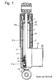
- a vibration damper comprises a cylinder 1, in which a piston rod 3 is arranged axially movable.
- a guiding and sealing unit 7 guides the piston rod 3 out of the upper end of the cylinder.
- a piston unit 9 is attached to the piston rod 3 with a piston valve assembly 11.
- the lower end of the cylinder 1 is closed by a bottom plate 13 with a bottom valve assembly 15.
- the cylinder 1 is enveloped by a container tube 17.
- the container tube 17 and an intermediate tube 5 form an annular space 19, which constitutes a compensation chamber.
- the space inside the cylinder 1 is divided by the piston unit 9 into a first working chamber 21 a and a second working chamber 21 b.
- the working chambers 21 a and 21 b are filled with Dämpf problemkeit.
- the compensation chamber 19 is filled to the level 19a with liquid and above it with gas.
- a first line section namely a high-pressure section 23, formed, which communicates via a bore 25 of the cylinder 1 with the second working chamber 21 b in connection.
- a laterally attached to the container tube 17 adjustable Dämpfventil worn 27 is followed by a laterally attached to the container tube 17 adjustable Dämpfventil worn 27. From this leads, not shown, one second line, namely a low pressure section 29, in the compensation chamber 19th
- the upper working chamber 21b decreases. An overpressure builds up in the upper working chamber 21b which can only dissipate into the lower working chamber 21a through the piston valve arrangement 11 as long as the adjustable damping valve device 27 is closed.
- the adjustable damper valve device 27 is opened, at the same time, liquid flows from the upper working chamber 21b through the high-pressure section 23 and the adjustable damper valve device 27 into the balancing chamber 19. The damping characteristic of the vibration damper during extension of the piston rod 3 is thus dependent on whether the adjustable damping valve 27 is more or less open or closed.
- the shock absorber when the damping valve 27 is open, the shock absorber also has a softer characteristic when retracted, when the adjustable damper valve device 27 is open and a harder characteristic when the damper valve device 27 is closed, just as when extending the piston rod. It should be noted that the flow direction through the high-pressure section 23 of the bypass is always the same, regardless of whether the piston rod extends or retracts.
- the Fig. 2 shows a first embodiment of the Dämpfventil worn 27.
- an outer housing 31 which is formed by a pipe socket of the container tube 17, a valve housing insert 33 is arranged.
- a lower disassemblable port 35 forms part of the high pressure section 23.
- the port 35 carries a valve seat disc 37 for a main stage valve body 39 of the adjustable damper valve device. Between the valve seat disc 37 and the port 35 may optionally be arranged an inlet valve 41.
- the main stage valve body 39 has a passage opening 43 which connects the high-pressure section 23 with a control chamber 45.
- at least one closing spring 47 is arranged for the main stage valve body 39.
- a precursor valve 53 is executed, which is arbitrary by a solenoid 55 as an actuator can be controlled.
- a precursor valve body 57 forms a seat valve together with the connection channel 49.
- a pressure level sets within the control chamber 45, the pressure force in addition to the closing force of the closing spring 47 counteracts a Abhubkraft in the high pressure section 23 to the main stage valve body 39.
- the precursor valve body 39 has an outer valve ring 59, which alternately at least one drain port 61 and at least two emergency operation channels 63a; 63b is driving.
- a biasing spring 65 biases the preliminary stage valve body 57 to a closed position with respect to the drainage port 61.
- the emergency operation channels 63a; 63b are designed in the valve housing insert 33 as radial channels, which in turn are connected to the collecting space 51.
- the adjustable damper valve device 27 has at least two emergency operation valves 69a; 69b, which have different opening characteristics. This different behavior is to be illustrated by the different size of the pictorial representations of the emergency operation valves. Deviating opening characteristic means that the opening force and the spring rate of at least one closing spring 71a; 71b of the emergency operation valves 69a; 69b are different.
- Each emergency operation valve 69a; 69b has its own housing 73a; 73b, in which a valve element 75a; 75b in this case a ball, from one inside the housing 73a; 73b arranged closing spring 71a; 71b is biased in a closed position.
- the closing spring 71a; 71b is adjustable in its closing force, z. B. by a support plate 77a; 77b for the closing spring 71a; 71b axially more or less deep into the housing 73a; 73b is screwed.
- Each emergency operation valve 69a; 69b is in turn via the housing 73a; 73b screwed into the valve housing insert 33.
- the biasing spring 65 presses the valve ring 59 of the pilot valve 53 in the direction of the drain opening 61 and closes it. With this closing movement, the emergency operation channels 63a; 63b effective.
- the damping force generated by the main stage valve body 39 is then determined by the sum of the passage cross sections of the emergency operation valves.
- FIG. 4 is a desired damping force characteristic shown.
- a first region of interest is determined by an opening first emergency valve 69a.
- Other emergency valves 73; 69b are still closed.
- the second emergency operation valve 69b At the intersection of the characteristics of two emergency valves 69a; 69b also opens the second emergency operation valve 69b, which is hydraulically connected in parallel with the first emergency operation valve 69a.
- a third emergency operating valve determines with its opening characteristic a third Kennhnien Scheme.
- the different slopes of the Characteristic ranges can be achieved, for example, by different spring rates of the respective closing springs 71 i.
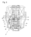
- the Fig. 3 shows an alternative solution to Fig. 2 , Deviating come not several emergency valves 69a; 69b for use, but a single emergency valve 69 includes a Dämpfventilaufsatz 79, which is arranged on the valve housing insert 33.
- a simple disk body can be used, which is externally attached to the valve housing insert 33.
- the Dämpfventilaufsatz 79 has at least one passageway 81, the outlet opening of at least one valve disc 83 is at least partially covered.
- the at least one valve disc 83 is biased by a central fastener 85 in conjunction with a disc spring 83 f on the Dämpfventilaufsatz 79.
- a distribution channel 87 is executed, which connects the emergency operating channel 63 in the valve housing insert 33 with the at least one passage 81 in the Dämpfventilaufsatz 79.
- the Dämpfventilaufsatz 79 is disposed in a stepped opening of the valve housing insert 33 and is based on a paragraph.
Applications Claiming Priority (1)
| Application Number | Priority Date | Filing Date | Title |
|---|---|---|---|
| DE102009002582A DE102009002582A1 (de) | 2009-04-23 | 2009-04-23 | Verstellbarer Schwingungsdämpfer mit einem Notbetriebventil |
Publications (3)
| Publication Number | Publication Date |
|---|---|
| EP2243979A2 true EP2243979A2 (fr) | 2010-10-27 |
| EP2243979A3 EP2243979A3 (fr) | 2012-04-18 |
| EP2243979B1 EP2243979B1 (fr) | 2013-10-02 |
Family
ID=42245944
Family Applications (1)
| Application Number | Title | Priority Date | Filing Date |
|---|---|---|---|
| EP20100160118 Not-in-force EP2243979B1 (fr) | 2009-04-23 | 2010-04-16 | Amortisseur d'oscillations réglable doté d'une soupape de fonctionnement d'urgence |
Country Status (2)
| Country | Link |
|---|---|
| EP (1) | EP2243979B1 (fr) |
| DE (1) | DE102009002582A1 (fr) |
Cited By (1)
| Publication number | Priority date | Publication date | Assignee | Title |
|---|---|---|---|---|
| CN115217882A (zh) * | 2022-06-14 | 2022-10-21 | 联合汽车电子有限公司 | 阻尼控制电磁阀 |
Families Citing this family (7)
| Publication number | Priority date | Publication date | Assignee | Title |
|---|---|---|---|---|
| KR101230550B1 (ko) | 2010-11-08 | 2013-02-07 | 주식회사 만도 | 쇽업소버의 감쇠력 가변 밸브 조립체 |
| KR20120049010A (ko) | 2010-11-08 | 2012-05-16 | 주식회사 만도 | 쇽업소버의 감쇠력 가변 밸브 조립체 |
| DE102010063386B4 (de) | 2010-12-17 | 2012-09-20 | Zf Friedrichshafen Ag | Verstellbare Dämpfventileinrichtung |
| CN103608263A (zh) | 2011-06-15 | 2014-02-26 | 宝洁公司 | 用于制造系统的模块和模块化制造系统 |
| DE102011079144B4 (de) | 2011-07-14 | 2013-02-07 | Zf Friedrichshafen Ag | Verstellbare Dämpfventileinrichtung mit einem Notbetriebventil |
| DE102014224976A1 (de) * | 2014-12-05 | 2016-06-09 | Zf Friedrichshafen Ag | Dämpfventil |
| DE102021200915B3 (de) | 2021-02-02 | 2022-07-14 | Zf Friedrichshafen Ag | Dämpfventileinrichtung für einen Schwingungsdämpfer |
Family Cites Families (6)
| Publication number | Priority date | Publication date | Assignee | Title |
|---|---|---|---|---|
| DE3937795A1 (de) * | 1989-05-26 | 1990-11-29 | Bosch Gmbh Robert | Stossdaempfer |
| DE3917064A1 (de) | 1989-05-26 | 1990-11-29 | Bosch Gmbh Robert | Stossdaempfer ii |
| DE3942545A1 (de) * | 1989-12-22 | 1991-06-27 | Bosch Gmbh Robert | Druckbetaetigtes ventil |
| DE4003595A1 (de) * | 1990-02-02 | 1991-08-08 | Siemens Ag | Verfahren zum bedrucken eines aufzeichnungstraegers mit einem druckkopf |
| DE4208886A1 (de) * | 1992-03-19 | 1993-09-23 | Fichtel & Sachs Ag | Daempfkraftveraenderbarer schwingungsdaempfer mit notbetriebseinstellung |
| JP3285302B2 (ja) * | 1994-10-21 | 2002-05-27 | ヤマハ発動機株式会社 | 減衰器 |
-
2009
- 2009-04-23 DE DE102009002582A patent/DE102009002582A1/de not_active Ceased
-
2010
- 2010-04-16 EP EP20100160118 patent/EP2243979B1/fr not_active Not-in-force
Non-Patent Citations (1)
| Title |
|---|
| None |
Cited By (1)
| Publication number | Priority date | Publication date | Assignee | Title |
|---|---|---|---|---|
| CN115217882A (zh) * | 2022-06-14 | 2022-10-21 | 联合汽车电子有限公司 | 阻尼控制电磁阀 |
Also Published As
| Publication number | Publication date |
|---|---|
| DE102009002582A1 (de) | 2010-10-28 |
| EP2243979B1 (fr) | 2013-10-02 |
| EP2243979A3 (fr) | 2012-04-18 |
Similar Documents
| Publication | Publication Date | Title |
|---|---|---|
| DE102009061003B4 (de) | Verstellbare Dämpfventileinrichtung | |
| EP2243979B1 (fr) | Amortisseur d'oscillations réglable doté d'une soupape de fonctionnement d'urgence | |
| EP2382520B1 (fr) | Soupape de régulation de pression proportionnelle et son utilisation pour connection hydraulique | |
| DE102011003924B4 (de) | Verstellbares Dämpfventil für einen Schwingungsdämpfer | |
| DE102005058846B4 (de) | Ventilbaukastensystem mit elektromagnetisch betätigtem Ventil | |
| DE102010063386B4 (de) | Verstellbare Dämpfventileinrichtung | |
| DE102012210459B3 (de) | Verstellbare Dämpfventileinrichtung | |
| EP3212958B1 (fr) | Procédé pour faire fonctionner un amortisseur de vibrations réglable destiné à des véhicules automobiles | |
| DE102007005288B4 (de) | Hydraulischer Schwingungsdämpfer | |
| DE102011010474A1 (de) | Proportional-Druckregelventil | |
| EP2505869A2 (fr) | Dispositif de robinet de vapeur réglable pour un amortisseur d'oscillations | |
| EP2159444A1 (fr) | Soupape à amortissement variable | |
| EP3047183B1 (fr) | Dispositif de commande pour effectuer sélectivement une connexion fluidique et une déconnexion de points de raccordement fluidique | |
| EP1226478B1 (fr) | Soupape, notamment soupape de regulation de pression | |
| EP1771675B1 (fr) | Soupape a commande electrique | |
| DE102010003958A1 (de) | Magnetventil | |
| EP2718602B1 (fr) | Soupape, en particulier soupape de régulation de pression ou soupape de limitation de pression | |
| EP2628974A2 (fr) | Dispositif de robinet de vapeur réglable pour un amortisseur dýoscillations | |
| DE102007005465A1 (de) | Elektrisch ansteuerbares Ventil | |
| EP2185988B1 (fr) | Limiteur de pression et arrangement d'un limiteur de pression pour piloter un régulateur de pression | |
| DE10308482B4 (de) | Elektromagnetventil | |
| EP1611358A1 (fr) | Soupape de distribution a variation continue | |
| WO2007082816A1 (fr) | Soupape électromagnétique | |
| EP2354589A2 (fr) | Valve d'amortissement réglable | |
| EP2028390A1 (fr) | Amortisseur d'oscillations réglable |
Legal Events
| Date | Code | Title | Description |
|---|---|---|---|
| PUAI | Public reference made under article 153(3) epc to a published international application that has entered the european phase |
Free format text: ORIGINAL CODE: 0009012 |
|
| AK | Designated contracting states |
Kind code of ref document: A2 Designated state(s): AT BE BG CH CY CZ DE DK EE ES FI FR GB GR HR HU IE IS IT LI LT LU LV MC MK MT NL NO PL PT RO SE SI SK SM TR |
|
| AX | Request for extension of the european patent |
Extension state: AL BA ME RS |
|
| PUAL | Search report despatched |
Free format text: ORIGINAL CODE: 0009013 |
|
| AK | Designated contracting states |
Kind code of ref document: A3 Designated state(s): AT BE BG CH CY CZ DE DK EE ES FI FR GB GR HR HU IE IS IT LI LT LU LV MC MK MT NL NO PL PT RO SE SI SK SM TR |
|
| AX | Request for extension of the european patent |
Extension state: AL BA ME RS |
|
| RIC1 | Information provided on ipc code assigned before grant |
Ipc: F16F 9/46 20060101AFI20120313BHEP |
|
| 17P | Request for examination filed |
Effective date: 20120912 |
|
| GRAP | Despatch of communication of intention to grant a patent |
Free format text: ORIGINAL CODE: EPIDOSNIGR1 |
|
| INTG | Intention to grant announced |
Effective date: 20130523 |
|
| GRAS | Grant fee paid |
Free format text: ORIGINAL CODE: EPIDOSNIGR3 |
|
| GRAA | (expected) grant |
Free format text: ORIGINAL CODE: 0009210 |
|
| AK | Designated contracting states |
Kind code of ref document: B1 Designated state(s): AT BE BG CH CY CZ DE DK EE ES FI FR GB GR HR HU IE IS IT LI LT LU LV MC MK MT NL NO PL PT RO SE SI SK SM TR |
|
| REG | Reference to a national code |
Ref country code: GB Ref legal event code: FG4D Free format text: NOT ENGLISH |
|
| REG | Reference to a national code |
Ref country code: AT Ref legal event code: REF Ref document number: 634765 Country of ref document: AT Kind code of ref document: T Effective date: 20131015 Ref country code: CH Ref legal event code: EP |
|
| REG | Reference to a national code |
Ref country code: IE Ref legal event code: FG4D Free format text: LANGUAGE OF EP DOCUMENT: GERMAN |
|
| REG | Reference to a national code |
Ref country code: DE Ref legal event code: R096 Ref document number: 502010004903 Country of ref document: DE Effective date: 20131205 |
|
| REG | Reference to a national code |
Ref country code: NL Ref legal event code: VDEP Effective date: 20131002 |
|
| PG25 | Lapsed in a contracting state [announced via postgrant information from national office to epo] |
Ref country code: SI Free format text: LAPSE BECAUSE OF FAILURE TO SUBMIT A TRANSLATION OF THE DESCRIPTION OR TO PAY THE FEE WITHIN THE PRESCRIBED TIME-LIMIT Effective date: 20131002 |
|
| REG | Reference to a national code |
Ref country code: LT Ref legal event code: MG4D |
|
| PG25 | Lapsed in a contracting state [announced via postgrant information from national office to epo] |
Ref country code: LT Free format text: LAPSE BECAUSE OF FAILURE TO SUBMIT A TRANSLATION OF THE DESCRIPTION OR TO PAY THE FEE WITHIN THE PRESCRIBED TIME-LIMIT Effective date: 20131002 Ref country code: FI Free format text: LAPSE BECAUSE OF FAILURE TO SUBMIT A TRANSLATION OF THE DESCRIPTION OR TO PAY THE FEE WITHIN THE PRESCRIBED TIME-LIMIT Effective date: 20131002 Ref country code: IS Free format text: LAPSE BECAUSE OF FAILURE TO SUBMIT A TRANSLATION OF THE DESCRIPTION OR TO PAY THE FEE WITHIN THE PRESCRIBED TIME-LIMIT Effective date: 20140202 Ref country code: NL Free format text: LAPSE BECAUSE OF FAILURE TO SUBMIT A TRANSLATION OF THE DESCRIPTION OR TO PAY THE FEE WITHIN THE PRESCRIBED TIME-LIMIT Effective date: 20131002 Ref country code: CZ Free format text: LAPSE BECAUSE OF FAILURE TO SUBMIT A TRANSLATION OF THE DESCRIPTION OR TO PAY THE FEE WITHIN THE PRESCRIBED TIME-LIMIT Effective date: 20131002 Ref country code: SE Free format text: LAPSE BECAUSE OF FAILURE TO SUBMIT A TRANSLATION OF THE DESCRIPTION OR TO PAY THE FEE WITHIN THE PRESCRIBED TIME-LIMIT Effective date: 20131002 Ref country code: NO Free format text: LAPSE BECAUSE OF FAILURE TO SUBMIT A TRANSLATION OF THE DESCRIPTION OR TO PAY THE FEE WITHIN THE PRESCRIBED TIME-LIMIT Effective date: 20140102 Ref country code: HR Free format text: LAPSE BECAUSE OF FAILURE TO SUBMIT A TRANSLATION OF THE DESCRIPTION OR TO PAY THE FEE WITHIN THE PRESCRIBED TIME-LIMIT Effective date: 20131002 |
|
| PG25 | Lapsed in a contracting state [announced via postgrant information from national office to epo] |
Ref country code: LV Free format text: LAPSE BECAUSE OF FAILURE TO SUBMIT A TRANSLATION OF THE DESCRIPTION OR TO PAY THE FEE WITHIN THE PRESCRIBED TIME-LIMIT Effective date: 20131002 Ref country code: ES Free format text: LAPSE BECAUSE OF FAILURE TO SUBMIT A TRANSLATION OF THE DESCRIPTION OR TO PAY THE FEE WITHIN THE PRESCRIBED TIME-LIMIT Effective date: 20131002 Ref country code: CY Free format text: LAPSE BECAUSE OF FAILURE TO SUBMIT A TRANSLATION OF THE DESCRIPTION OR TO PAY THE FEE WITHIN THE PRESCRIBED TIME-LIMIT Effective date: 20131002 Ref country code: PL Free format text: LAPSE BECAUSE OF FAILURE TO SUBMIT A TRANSLATION OF THE DESCRIPTION OR TO PAY THE FEE WITHIN THE PRESCRIBED TIME-LIMIT Effective date: 20131002 |
|
| PG25 | Lapsed in a contracting state [announced via postgrant information from national office to epo] |
Ref country code: PT Free format text: LAPSE BECAUSE OF FAILURE TO SUBMIT A TRANSLATION OF THE DESCRIPTION OR TO PAY THE FEE WITHIN THE PRESCRIBED TIME-LIMIT Effective date: 20140203 |
|
| REG | Reference to a national code |
Ref country code: DE Ref legal event code: R097 Ref document number: 502010004903 Country of ref document: DE |
|
| PG25 | Lapsed in a contracting state [announced via postgrant information from national office to epo] |
Ref country code: EE Free format text: LAPSE BECAUSE OF FAILURE TO SUBMIT A TRANSLATION OF THE DESCRIPTION OR TO PAY THE FEE WITHIN THE PRESCRIBED TIME-LIMIT Effective date: 20131002 |
|
| PGFP | Annual fee paid to national office [announced via postgrant information from national office to epo] |
Ref country code: GB Payment date: 20140416 Year of fee payment: 5 |
|
| PLBE | No opposition filed within time limit |
Free format text: ORIGINAL CODE: 0009261 |
|
| STAA | Information on the status of an ep patent application or granted ep patent |
Free format text: STATUS: NO OPPOSITION FILED WITHIN TIME LIMIT |
|
| PG25 | Lapsed in a contracting state [announced via postgrant information from national office to epo] |
Ref country code: RO Free format text: LAPSE BECAUSE OF FAILURE TO SUBMIT A TRANSLATION OF THE DESCRIPTION OR TO PAY THE FEE WITHIN THE PRESCRIBED TIME-LIMIT Effective date: 20131002 Ref country code: SK Free format text: LAPSE BECAUSE OF FAILURE TO SUBMIT A TRANSLATION OF THE DESCRIPTION OR TO PAY THE FEE WITHIN THE PRESCRIBED TIME-LIMIT Effective date: 20131002 Ref country code: IT Free format text: LAPSE BECAUSE OF FAILURE TO SUBMIT A TRANSLATION OF THE DESCRIPTION OR TO PAY THE FEE WITHIN THE PRESCRIBED TIME-LIMIT Effective date: 20131002 |
|
| PGFP | Annual fee paid to national office [announced via postgrant information from national office to epo] |
Ref country code: FR Payment date: 20140409 Year of fee payment: 5 |
|
| 26N | No opposition filed |
Effective date: 20140703 |
|
| PG25 | Lapsed in a contracting state [announced via postgrant information from national office to epo] |
Ref country code: DK Free format text: LAPSE BECAUSE OF FAILURE TO SUBMIT A TRANSLATION OF THE DESCRIPTION OR TO PAY THE FEE WITHIN THE PRESCRIBED TIME-LIMIT Effective date: 20131002 |
|
| REG | Reference to a national code |
Ref country code: DE Ref legal event code: R097 Ref document number: 502010004903 Country of ref document: DE Effective date: 20140703 |
|
| PG25 | Lapsed in a contracting state [announced via postgrant information from national office to epo] |
Ref country code: MC Free format text: LAPSE BECAUSE OF FAILURE TO SUBMIT A TRANSLATION OF THE DESCRIPTION OR TO PAY THE FEE WITHIN THE PRESCRIBED TIME-LIMIT Effective date: 20131002 Ref country code: LU Free format text: LAPSE BECAUSE OF FAILURE TO SUBMIT A TRANSLATION OF THE DESCRIPTION OR TO PAY THE FEE WITHIN THE PRESCRIBED TIME-LIMIT Effective date: 20140416 |
|
| REG | Reference to a national code |
Ref country code: CH Ref legal event code: PL |
|
| REG | Reference to a national code |
Ref country code: IE Ref legal event code: MM4A |
|
| PG25 | Lapsed in a contracting state [announced via postgrant information from national office to epo] |
Ref country code: LI Free format text: LAPSE BECAUSE OF NON-PAYMENT OF DUE FEES Effective date: 20140430 Ref country code: CH Free format text: LAPSE BECAUSE OF NON-PAYMENT OF DUE FEES Effective date: 20140430 |
|
| PG25 | Lapsed in a contracting state [announced via postgrant information from national office to epo] |
Ref country code: IE Free format text: LAPSE BECAUSE OF NON-PAYMENT OF DUE FEES Effective date: 20140416 |
|
| PGFP | Annual fee paid to national office [announced via postgrant information from national office to epo] |
Ref country code: DE Payment date: 20150408 Year of fee payment: 6 |
|
| GBPC | Gb: european patent ceased through non-payment of renewal fee |
Effective date: 20150416 |
|
| PG25 | Lapsed in a contracting state [announced via postgrant information from national office to epo] |
Ref country code: GB Free format text: LAPSE BECAUSE OF NON-PAYMENT OF DUE FEES Effective date: 20150416 |
|
| REG | Reference to a national code |
Ref country code: FR Ref legal event code: ST Effective date: 20151231 |
|
| PG25 | Lapsed in a contracting state [announced via postgrant information from national office to epo] |
Ref country code: FR Free format text: LAPSE BECAUSE OF NON-PAYMENT OF DUE FEES Effective date: 20150430 |
|
| PG25 | Lapsed in a contracting state [announced via postgrant information from national office to epo] |
Ref country code: MT Free format text: LAPSE BECAUSE OF FAILURE TO SUBMIT A TRANSLATION OF THE DESCRIPTION OR TO PAY THE FEE WITHIN THE PRESCRIBED TIME-LIMIT Effective date: 20131002 |
|
| PG25 | Lapsed in a contracting state [announced via postgrant information from national office to epo] |
Ref country code: NO Free format text: LAPSE BECAUSE OF FAILURE TO SUBMIT A TRANSLATION OF THE DESCRIPTION OR TO PAY THE FEE WITHIN THE PRESCRIBED TIME-LIMIT Effective date: 20140101 Ref country code: SM Free format text: LAPSE BECAUSE OF FAILURE TO SUBMIT A TRANSLATION OF THE DESCRIPTION OR TO PAY THE FEE WITHIN THE PRESCRIBED TIME-LIMIT Effective date: 20131002 |
|
| REG | Reference to a national code |
Ref country code: AT Ref legal event code: MM01 Ref document number: 634765 Country of ref document: AT Kind code of ref document: T Effective date: 20150416 |
|
| PG25 | Lapsed in a contracting state [announced via postgrant information from national office to epo] |
Ref country code: BG Free format text: LAPSE BECAUSE OF FAILURE TO SUBMIT A TRANSLATION OF THE DESCRIPTION OR TO PAY THE FEE WITHIN THE PRESCRIBED TIME-LIMIT Effective date: 20131002 Ref country code: GR Free format text: LAPSE BECAUSE OF FAILURE TO SUBMIT A TRANSLATION OF THE DESCRIPTION OR TO PAY THE FEE WITHIN THE PRESCRIBED TIME-LIMIT Effective date: 20140103 |
|
| PG25 | Lapsed in a contracting state [announced via postgrant information from national office to epo] |
Ref country code: BE Free format text: LAPSE BECAUSE OF FAILURE TO SUBMIT A TRANSLATION OF THE DESCRIPTION OR TO PAY THE FEE WITHIN THE PRESCRIBED TIME-LIMIT Effective date: 20140430 Ref country code: TR Free format text: LAPSE BECAUSE OF FAILURE TO SUBMIT A TRANSLATION OF THE DESCRIPTION OR TO PAY THE FEE WITHIN THE PRESCRIBED TIME-LIMIT Effective date: 20131002 Ref country code: HU Free format text: LAPSE BECAUSE OF FAILURE TO SUBMIT A TRANSLATION OF THE DESCRIPTION OR TO PAY THE FEE WITHIN THE PRESCRIBED TIME-LIMIT; INVALID AB INITIO Effective date: 20100416 |
|
| PG25 | Lapsed in a contracting state [announced via postgrant information from national office to epo] |
Ref country code: AT Free format text: LAPSE BECAUSE OF NON-PAYMENT OF DUE FEES Effective date: 20150416 |
|
| REG | Reference to a national code |
Ref country code: DE Ref legal event code: R119 Ref document number: 502010004903 Country of ref document: DE |
|
| PG25 | Lapsed in a contracting state [announced via postgrant information from national office to epo] |
Ref country code: DE Free format text: LAPSE BECAUSE OF NON-PAYMENT OF DUE FEES Effective date: 20161101 |
|
| PG25 | Lapsed in a contracting state [announced via postgrant information from national office to epo] |
Ref country code: MK Free format text: LAPSE BECAUSE OF FAILURE TO SUBMIT A TRANSLATION OF THE DESCRIPTION OR TO PAY THE FEE WITHIN THE PRESCRIBED TIME-LIMIT Effective date: 20131002 |