EP2243971B1 - Klammerbefestigungsstruktur - Google Patents
Klammerbefestigungsstruktur Download PDFInfo
- Publication number
- EP2243971B1 EP2243971B1 EP09703238.7A EP09703238A EP2243971B1 EP 2243971 B1 EP2243971 B1 EP 2243971B1 EP 09703238 A EP09703238 A EP 09703238A EP 2243971 B1 EP2243971 B1 EP 2243971B1
- Authority
- EP
- European Patent Office
- Prior art keywords
- wall body
- clip
- retaining
- rib
- retaining hole
- Prior art date
- Legal status (The legal status is an assumption and is not a legal conclusion. Google has not performed a legal analysis and makes no representation as to the accuracy of the status listed.)
- Not-in-force
Links
Images


Classifications
-
- F—MECHANICAL ENGINEERING; LIGHTING; HEATING; WEAPONS; BLASTING
- F16—ENGINEERING ELEMENTS AND UNITS; GENERAL MEASURES FOR PRODUCING AND MAINTAINING EFFECTIVE FUNCTIONING OF MACHINES OR INSTALLATIONS; THERMAL INSULATION IN GENERAL
- F16B—DEVICES FOR FASTENING OR SECURING CONSTRUCTIONAL ELEMENTS OR MACHINE PARTS TOGETHER, e.g. NAILS, BOLTS, CIRCLIPS, CLAMPS, CLIPS OR WEDGES; JOINTS OR JOINTING
- F16B21/00—Means for preventing relative axial movement of a pin, spigot, shaft or the like and a member surrounding it; Stud-and-socket releasable fastenings
- F16B21/06—Releasable fastening devices with snap-action
- F16B21/08—Releasable fastening devices with snap-action in which the stud, pin, or spigot has a resilient part
- F16B21/086—Releasable fastening devices with snap-action in which the stud, pin, or spigot has a resilient part the shank of the stud, pin or spigot having elevations, ribs, fins or prongs intended for deformation or tilting predominantly in a direction perpendicular to the direction of insertion
-
- Y—GENERAL TAGGING OF NEW TECHNOLOGICAL DEVELOPMENTS; GENERAL TAGGING OF CROSS-SECTIONAL TECHNOLOGIES SPANNING OVER SEVERAL SECTIONS OF THE IPC; TECHNICAL SUBJECTS COVERED BY FORMER USPC CROSS-REFERENCE ART COLLECTIONS [XRACs] AND DIGESTS
- Y10—TECHNICAL SUBJECTS COVERED BY FORMER USPC
- Y10T—TECHNICAL SUBJECTS COVERED BY FORMER US CLASSIFICATION
- Y10T24/00—Buckles, buttons, clasps, etc.
- Y10T24/30—Trim molding fastener
- Y10T24/309—Plastic type
-
- Y—GENERAL TAGGING OF NEW TECHNOLOGICAL DEVELOPMENTS; GENERAL TAGGING OF CROSS-SECTIONAL TECHNOLOGIES SPANNING OVER SEVERAL SECTIONS OF THE IPC; TECHNICAL SUBJECTS COVERED BY FORMER USPC CROSS-REFERENCE ART COLLECTIONS [XRACs] AND DIGESTS
- Y10—TECHNICAL SUBJECTS COVERED BY FORMER USPC
- Y10T—TECHNICAL SUBJECTS COVERED BY FORMER US CLASSIFICATION
- Y10T24/00—Buckles, buttons, clasps, etc.
- Y10T24/44—Clasp, clip, support-clamp, or required component thereof
- Y10T24/44017—Clasp, clip, support-clamp, or required component thereof with specific mounting means for attaching to rigid or semirigid supporting structure or structure-to-be-secured
- Y10T24/44026—Clasp, clip, support-clamp, or required component thereof with specific mounting means for attaching to rigid or semirigid supporting structure or structure-to-be-secured for cooperating with aperture in supporting structure or structure-to-be-secured
-
- Y—GENERAL TAGGING OF NEW TECHNOLOGICAL DEVELOPMENTS; GENERAL TAGGING OF CROSS-SECTIONAL TECHNOLOGIES SPANNING OVER SEVERAL SECTIONS OF THE IPC; TECHNICAL SUBJECTS COVERED BY FORMER USPC CROSS-REFERENCE ART COLLECTIONS [XRACs] AND DIGESTS
- Y10—TECHNICAL SUBJECTS COVERED BY FORMER USPC
- Y10T—TECHNICAL SUBJECTS COVERED BY FORMER US CLASSIFICATION
- Y10T24/00—Buckles, buttons, clasps, etc.
- Y10T24/45—Separable-fastener or required component thereof [e.g., projection and cavity to complete interlock]
- Y10T24/45005—Separable-fastener or required component thereof [e.g., projection and cavity to complete interlock] with third detached member completing interlock [e.g., hook type]
- Y10T24/45099—Resilient element [e.g., snap type]
- Y10T24/45105—Resilient element [e.g., snap type] for upholstery, panel, trim strip, etc. [e.g., spring biased]
Definitions
- the present invention relates to an clip assembly having elastic retaining pieces. More particularly, the present invention relates to the clip assembly which the elastic retaining pieces are fit in a retaining hole in a wall body of a mounting member or others so as to be attached stably.
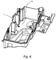
- FIG. 6 is a perspective view of the attachment structure.
- Fig. 7 is a plan view as seen from the top in Fig. 6 , and A indicates a position where the clip is attached to the wall body of the mounting member.
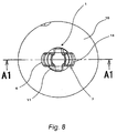
- Fig. 8 is an enlarged view of the portion A of Fig. 7 .
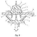
- FIG. 9 is a cross-sectional view taken along the line A1-A1 of Fig. 8 .
- the clip assembly shown in Figs. 6 to 9 comprises a retaining hole 11 formed in the wall body 10 of the mounting member, and the clip 1 having a retaining head 7 to be inserted in this retaining hole 11.
- This clip 1 includes a base portion 2 holding an article such as a wire harness or a base portion 2 attached to other equipment body, a clip pillar 3 formed upright on this base portion 2, the retaining head 7 comprising a pair of elastic retaining pieces 4, 4 depending from this clip pillar 3, and a pair of elastically-bendable press-contacting pieces 6 formed on and extending slantingly from the base portion 2.
- the retaining head 7 of the clip 1 is inserted into the retaining hole 11 in the wall body 10 from the outer side of the wall body 10 toward the inner side thereof. Then, the elastic retaining pieces 4 are pressed in a closing direction by an inner peripheral edge of the retaining hole 11 and are deformed, and when the retaining head 7 is further inserted deeper, step retaining portions 5 of the elastic retaining pieces 4 reach an upper end portion of the retaining hole 11, and the elastic retaining pieces 4 are elastically restored in an opening direction, so that the retaining step retaining portions 5 are retained on an open edge portion of the retaining hole 11.
- the clip 1 is attached to the wall body 10 of the mounting member, and in this condition, when some force F1, F2, F3 was applied to the clip 1 (see Fig. 9 ), there was a possibility that the portion around the retaining hole 11 was deformed depending on the thickness T and material of the wall body 10 of the mounting member, so that the retaining engagement of the step retaining portions 5 of the elastic retaining pieces 4 with the open edge portion of the retaining hole 11 might be canceled.
- the function of the press-contacting pieces 6, that is, the function of preventing the shaking of the clip 1 can not be efficiently performed if the relation between a length L2 from a retaining surface of the step retaining portion 5 of the elastic retaining piece 4 to a press-contact surface of the press-contacting piece 6 and the thickness T of the wall body 10 of the mounting member is not so determined as to establish L2 ⁇ T, that is, if a clearance L1 is not provided between the press-contact surface of the press-contacting piece 6 and the wall body 10 of the mounting member.
- the length L2 between the retaining surface of the step retaining portion 5 of the elastic retaining piece 4 and the press-contact surface of the press-contacting piece 6 must be selected according to the thickness T of the wall body 10 of the mounting member, and therefore the range of selection of the clip was narrow.
- JP-A-2007-255610 shows a chip assembly with a single rib structure.
- the present invention seeks to solve the problems of the above conventional clip assembly having the elastic retaining pieces, and an object thereof is to provide an clip assembly in which merely by adding a simple construction to a wall body of a mounting member, deformation of that portion around a retaining hole is eliminated, and the clip can be attached in a stable condition.
- the clip assembly of the present invention merely by adding the simple construction to the wall body of the mounting member, deformation of the portion around the retaining hole is eliminated, and the clip can be attached in a stable condition.
- the shaking of the clip can be reduced, and the range of selection of the clip to be used can be increased.
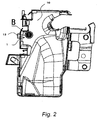
- an clip assembly according to the present invention comprises a retaining hole 11 formed in a wall body 10 of an electrical equipment serving as a mounting member, and a synthetic resin-made clip 1 having a retaining head for passing through this retaining hole 11.
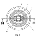
- the wall body 10 includes a first rib 12 formed integrally with the wall body 10 and disposed around the retaining hole 11 in concentric relation to the retaining hole 11, and a second rib 13 formed integrally with the wall body 10 and disposed outside the first rib 12 in concentric relation to the first rib 12 and in surrounding relation to the retaining head 7 passing through this retaining hole 11.
- the clip 1 includes a base portion 2 having such a structure that it can hold an article such as a wire harness or a base portion 2 of such a structure as to be attached to other equipment body, a clip pillar 3 formed upright on this base portion 2, and the retaining head 7 comprising a pair of elastic retaining pieces 4, 4 depending from this clip pillar 3.
- the clip 1 further includes a pair of elastically-bendable press-contacting pieces 6 formed on and extending slantingly from the base portion 2.
- wall bodies of an electrical equipment such as a protector, a fuse box, a relay box, a joint box and so on, and a vehicle interior are given.
- the first rib 12 is formed on the inner side of the wall body 10, and is formed into such a height that in a condition in which the clip 1 is inserted in the retaining hole 11, and retaining surfaces of step retaining portions 5 of the elastic retaining pieces 4 are retained on the first rib, the press-contacting pieces 6 of the clip 1 is disposed in an abutting condition relative to the outer side of the wall body 10.
- the second rib 13 is formed outside the first rib 12 in concentric relation to the first rib 12, and is formed into a height larger than the height of the first rib 12, and with respect to its height, the second rib is constructed such that its height from the wall body 10 is not smaller than the height from the wall body 10 to the retaining head 7 of the clip 1.
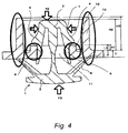
- the retaining head 7 of the clip 1 is inserted into the retaining hole 11 in the wall body 10. Then, the elastic retaining pieces 4 are pressed in a closing direction by an inner peripheral edge of the retaining hole 11 and are deformed, and when the retaining head 7 is further inserted deeper, the step retaining portions 5 of the elastic retaining pieces 4 reach an open edge portion of an upper end portion of the retaining hole 11, that is, an open edge portion of an upper end portion of the first rib 12 formed around the retaining hole 11, and the elastic retaining pieces 4 are elastically restored in an opening direction, so that the retaining step retaining portions 5 are retained on the open edge portion of the upper end portion of the first rib 12. In the condition in which the clip 1 is attached to the wall body 10 of the mounting member, the retaining head 7 of the clip 1 projecting from the retaining hole 11 in the wall body 10 is surrounded by the second rib 13.
- the first rib 12 is formed at the wall body 10 of the mounting member such that a thickness T of that portion around the retaining hole 11 is increased, and therefore a strength of this portion is increased. Therefore, there will not be encountered a situation as in the conventional example in which when some force F1, F2, F3 is applied (see Fig. 4 ), the portion around the retaining hole 11 is deformed, and therefore the retaining engagement of the step retaining portions 5 of the elastic retaining pieces 4 with the open edge portion of the retaining hole 11 will not be canceled.
- the wall body 10 of the mounting member itself can cover the reduction of the strength due to the formation of the retaining hole 11 by a reinforcing effect of the first rib 12, and therefore the reduction of the strength of a mounting member body will not be invited.
- the second rib 13 formed on the wall body 10 surrounds the retaining head 7 of the clip 1 projecting from the retaining hole 11 in the wall body 10, and the height H3 of the second rib 13 from the wall body 10 is not smaller than the height H2 from the wall body 10 to the retaining head 7 of the clip 1. Therefore, the second rib prevents any other member such as an electric wire from contacting the retaining head 7 of the clip 1 and also from contacting the elastic retaining pieces 4 of the clip 1. Therefore, the elastic retaining pieces 4 will not be deformed in the closing direction, and the retaining engagement of the step retaining portions 5 of the elastic retaining pieces 4 with the open edge portion of the retaining hole 11 will not be canceled.
- the second rib 13 formed on the wall body 10 is formed integrally with the wall body 10, and therefore reinforces the wall body 10, and it can be said that the second rib has the function of preventing the retaining engagement of the step retaining portions 5 of the elastic retaining pieces 4 with the open edge portion of the retaining hole 11 from being canceled.
- a design is made to increase the thickness T of the portion around the retaining hole 11 according to the size of the clip 1 to be used, thus adjusting the height H1 of the first rib 12, and the relation between a length L2 from the retaining surface of the step retaining portion 5 of the elastic retaining piece 4 to a press-contact surface at the distal end of the press-contacting piece 6 and a value obtained by adding a height H1 of the first rib 12 to the thickness T of the wall body 10 of the mounting member is so adjusted that L2 ⁇ T + H1 can be established, that is, by adjustments, there can be created such a relation that a clearance L3 will not be formed between the press-contact surface of the press-contacting piece 6 and the wall body 10 of the mounting member, and therefore this can be conformed to the size of the clip 1 to be used, and the function of preventing the shaking of the clip 1 can be efficiently performed.
- the first rib 12 formed around the retaining hole 11 it can be formed integrally with the wall body 10 of the mounting member simultaneously with the formation of the wall body 10, using the same material as the wall body 10. In another case, it can be formed integrally with the wall body 10 of the mounting member simultaneously with the formation of the wall body 10, using a different material from that of the wall body 10. In a further case, separately from the formation of the wall body 10 of the mounting member, one made of either the same material as the wall body 10 or a different material can be formed integrally therewith by an adhesive or others. Also, the shape can be any of various shapes such as an annular shape, a rectangular shape and so on in so far as the purpose can be achieved. In short, if the first rib 12 has such a structure as to provide reinforcement against deformation of the retaining piece 11, this is sufficient.
- the first rib 12 is free to be formed on either side of the wall body 10, and the inner side which is the side where the retaining head 7 of the clip 1 is received is preferred, but from the viewpoint of the strength, it may, of course, be formed on the opposite side.
- the form of the second rib 13 formed around the retaining hole 11 is similar to the form of the first rib 12, and it can be formed integrally with the wall body 10 of the mounting member simultaneously with the formation of the wall body 10, using the same material as the wall body 10. In another case, it can be formed integrally with the wall body 10 of the mounting member simultaneously with the formation of the wall body 10, using a different material from that of the wall body 10. In a further case, separately from the formation of the wall body 10 of the mounting member, one made of either the same material as the wall body 10 or a different material can be formed integrally therewith by an adhesive or others. Also, the shape can be any of various shapes such as an annular shape, a rectangular shape and so on in so far as the purpose can be achieved. In short, if the second rib 13 has such a structure that it can prevent any other member such as an electric wire from contacting the retaining head 7 and the elastic retaining pieces 4 of the clip 1, this is sufficient.
- the height H3 of the second rib 13 be not smaller than the height H2 of the retaining head 7 of the clip, one lower than the height H2 of the retaining head 7 of the clip can be selected depending on an expected size of an article and an expected magnitude of a force.
- the clip assembly of the present invention merely by adding the simple construction to the wall body of the mounting member, deformation of the portion around the retaining hole is eliminated, and the clip can be attached in a stable condition. Also, merely by adjusting the dimensions of the construction to be added to the wall body of the mounting member, the shaking of the clip can be reduced, and the range of selection of the clip to be used can be increased.
- FIG. 5 An clip assembly according to an embodiment 2 of the present invention will be described with reference to Fig. 5 .
- the same reference numerals as in Fig. 4 designate the same members, respectively, and therefore repeated description will be omitted.
- the embodiment 2 differs from the embodiment 1 in that although the outer side of the wall body 10 of the electrical equipment serving as the mounting member is flat over the entire area thereof in the embodiment 1, an outer side of a wall body 10 is not flat over an entire area thereof in the embodiment 2, and a raised portion 14 is formed on the opposite face only at that side where a first rib 12 and a second rib 13 are provided, thereby forming a wall thickness of T' as a whole.
- the reinforcement against the reduction of the mechanical strength due to the formation of the retaining hole 11 in the wall body 10 is made by the first rib 12 and the second rib 13 in the embodiment 1, and further the reinforcement is made by the raised portion 14 of T' - T on the opposite face of the wall body 10 in the embodiment 2.
- the wall thickness of the wall body is increased only at the portion of the wall body of the mounting member in which the retaining hole 11 is formed, deformation of the portion around the retaining hole is eliminated, and the clip can be attached in the stable condition. Also, merely by adjusting the dimensions of the construction to be added to the wall body of the mounting member, the shaking of the clip can be reduced, and the range of selection of the clip to be used can be increased.
- the deformation of the portion around the retaining hole is eliminated, and the clip can be attached in the stable condition, and the range of selection of the clip to be used can be increased.
Landscapes
- Engineering & Computer Science (AREA)
- General Engineering & Computer Science (AREA)
- Mechanical Engineering (AREA)
- Insertion Pins And Rivets (AREA)
- Connection Of Plates (AREA)
- Clamps And Clips (AREA)
Claims (4)
- Klemmenanordnung, wobei ein Teil der Klemme (1) in ein Halteloch (11), das in einem Wand-Körper (10) ausgebildet ist, von einer Außenseite des Wand-Körpers (10) her auf eine Innenseite desselben zu eingeführt wird und darin gehalten wird, so dass die Klemme (1) an dem Halteloch (11) angebracht ist, und die Anbringungsstruktur umfasst:ein elastisches Halteteil (4), das in das Halteloch (11) eingeführt wird und dabei elastisch verformt wird, so dass es in dem Halteloch (11) gehalten wird,dadurch gekennzeichnet, dasseine Rippenstruktur, die um das Halteloch (11) herum angeordnet ist, integral mit dem Wand-Körper (10) ausgebildet ist, undwobei die Rippenstruktur einschließt:eine erste Rippe (12), die an der Innenseite des Wand-Körpers (10) ausgebildet ist und eine solche Höhe (H1) hat, dass ein Presskontaktteil (6) der Klemme (1) an der Außenseite des Wand-Körpers (10) anliegt, wenn das elastische Halteteil (4) in das Halteloch (11) eingeführt ist und an der ersten Rippe (12) gehalten wird; undeine zweite Rippe (13), die außerhalb der ersten Rippe (12) konzentrisch zu der ersten Rippe (12) ausgebildet ist und eine Höhe (H3) hat, die größer ist als die Höhe (H1) der ersten Rippe (12).
- Klemmenanordnung nach Anspruch 1, wobei:eine Höhe (H3) der zweiten Rippe (13) von dem Wand-Körper (10) aus nicht kleiner ist als eine Höhe (H2) von dem Wand-Körper (10) aus bis zu einem Haltekopf (7) der Klemme (1).
- Klemmenanordnung nach Anspruch 1, wobei:ein erhöhter Abschnitt (14) an der Außenseite des Wand-Körpers (10) integral mit dem Wand-Körper (10) nur an einem Abschnitt des Wand-Körpers (10) ausgebildet ist, an dem das Halteloch (11) ausgebildet ist.
- Klemmenanordnung nach Anspruch 2, wobei
ein erhöhter Abschnitt (14) an der Außenseite des Wand-Körpers (10) integral mit dem Wand-Körper (10) nur an einem Abschnitt des Wand-Körpers (10) ausgebildet ist, in dem das Halteloch (11) ausgebildet ist.
Applications Claiming Priority (2)
| Application Number | Priority Date | Filing Date | Title |
|---|---|---|---|
| JP2008013064A JP5110698B2 (ja) | 2008-01-23 | 2008-01-23 | クリップの取付構造 |
| PCT/JP2009/050886 WO2009093614A1 (ja) | 2008-01-23 | 2009-01-21 | クリップの取付構造 |
Publications (3)
| Publication Number | Publication Date |
|---|---|
| EP2243971A1 EP2243971A1 (de) | 2010-10-27 |
| EP2243971A4 EP2243971A4 (de) | 2014-03-05 |
| EP2243971B1 true EP2243971B1 (de) | 2016-08-31 |
Family
ID=40901122
Family Applications (1)
| Application Number | Title | Priority Date | Filing Date |
|---|---|---|---|
| EP09703238.7A Not-in-force EP2243971B1 (de) | 2008-01-23 | 2009-01-21 | Klammerbefestigungsstruktur |
Country Status (5)
| Country | Link |
|---|---|
| US (1) | US8601650B2 (de) |
| EP (1) | EP2243971B1 (de) |
| JP (1) | JP5110698B2 (de) |
| CN (1) | CN101925752A (de) |
| WO (1) | WO2009093614A1 (de) |
Families Citing this family (7)
| Publication number | Priority date | Publication date | Assignee | Title |
|---|---|---|---|---|
| JP5650552B2 (ja) * | 2011-02-01 | 2015-01-07 | 大和化成工業株式会社 | 防水クリップ |
| US20120257924A1 (en) * | 2011-04-06 | 2012-10-11 | Jeffrey Andrews | Molded attachment clip |
| JP5886490B2 (ja) * | 2011-06-23 | 2016-03-16 | トヨタ自動車株式会社 | ホイールカバー |
| JP6162437B2 (ja) * | 2013-03-07 | 2017-07-12 | 大和化成工業株式会社 | クリップ |
| CN109518964B (zh) * | 2018-12-06 | 2020-09-15 | 深圳市前海格锐建筑技术有限公司 | 安装拆卸工具 |
| DE102019109763B4 (de) * | 2019-04-12 | 2025-11-13 | Bayerische Motoren Werke Aktiengesellschaft | Clip sowie Kraftfahrzeug mit einem solchen |
| DE102020204176A1 (de) * | 2020-03-31 | 2021-09-30 | Witte Automotive Gmbh | Befestigungselement |
Family Cites Families (17)
| Publication number | Priority date | Publication date | Assignee | Title |
|---|---|---|---|---|
| US2946612A (en) * | 1958-02-24 | 1960-07-26 | Amerock Corp | Self-alining catch |
| US3909883A (en) * | 1972-02-28 | 1975-10-07 | Richco Plastic Co | Locking base for plastic components |
| US3776580A (en) * | 1972-02-28 | 1973-12-04 | Micro & Precision Mouldings Lt | Catches |
| US3988808A (en) * | 1975-08-08 | 1976-11-02 | Hartwell Corporation | Readily mounted separable fastener |
| JPS53133413U (de) * | 1977-03-29 | 1978-10-23 | ||
| JPS5838020U (ja) * | 1981-09-07 | 1983-03-12 | 松下電器産業株式会社 | 取付装置 |
| JPS6057826U (ja) * | 1983-09-22 | 1985-04-22 | 小島プレス工業株式会社 | レバ−の取付構造 |
| JPH0544713A (ja) * | 1991-08-08 | 1993-02-23 | Nippondenso Co Ltd | リンクプレート係止構造 |
| JP2583709B2 (ja) | 1991-12-13 | 1997-02-19 | 矢崎総業株式会社 | クリップの取付構造 |
| JP3250359B2 (ja) | 1994-01-21 | 2002-01-28 | 住友電装株式会社 | 壁板用クランプ |
| DE9411165U1 (de) * | 1994-07-09 | 1994-09-08 | Panduit GmbH, 61352 Bad Homburg | Spreizanker |
| US6572317B2 (en) * | 2000-09-14 | 2003-06-03 | Piolax Inc. | Resilient fastener clip |
| JP2005042770A (ja) | 2003-07-24 | 2005-02-17 | Sumitomo Wiring Syst Ltd | クランプの係止構造 |
| JP4649120B2 (ja) * | 2004-04-30 | 2011-03-09 | 株式会社パイオラックス | クリップ |
| JP4329687B2 (ja) * | 2004-12-27 | 2009-09-09 | 三菱自動車工業株式会社 | ケーブル保持構造 |
| JP4533862B2 (ja) * | 2006-03-23 | 2010-09-01 | 矢崎総業株式会社 | クリップの取付構造 |
| JP2008013064A (ja) | 2006-07-06 | 2008-01-24 | Nissan Motor Co Ltd | 自動車用内燃機関の運転音伝達装置 |
-
2008
- 2008-01-23 JP JP2008013064A patent/JP5110698B2/ja not_active Expired - Fee Related
-
2009
- 2009-01-21 US US12/864,027 patent/US8601650B2/en not_active Expired - Fee Related
- 2009-01-21 EP EP09703238.7A patent/EP2243971B1/de not_active Not-in-force
- 2009-01-21 CN CN2009801028779A patent/CN101925752A/zh active Pending
- 2009-01-21 WO PCT/JP2009/050886 patent/WO2009093614A1/ja not_active Ceased
Also Published As
| Publication number | Publication date |
|---|---|
| JP5110698B2 (ja) | 2012-12-26 |
| EP2243971A4 (de) | 2014-03-05 |
| JP2009174617A (ja) | 2009-08-06 |
| WO2009093614A4 (ja) | 2009-10-29 |
| US20100293762A1 (en) | 2010-11-25 |
| WO2009093614A1 (ja) | 2009-07-30 |
| EP2243971A1 (de) | 2010-10-27 |
| CN101925752A (zh) | 2010-12-22 |
| US8601650B2 (en) | 2013-12-10 |
Similar Documents
| Publication | Publication Date | Title |
|---|---|---|
| EP2243971B1 (de) | Klammerbefestigungsstruktur | |
| US7422443B2 (en) | Electric connection box | |
| US8907215B2 (en) | Corrugated tube protector | |
| EP2882057A1 (de) | Öse | |
| JP2009165216A (ja) | コルゲートクランプ | |
| CN101305853A (zh) | 保持器具 | |
| US10141679B2 (en) | Electrical connector | |
| EP3444485B1 (de) | Befestigungselement und befestigungselementeanordnung | |
| JP2017017964A (ja) | 電線収容プロテクタ | |
| US20140060880A1 (en) | Protector of electric wire for allowing movement of fixation object | |
| JP4283136B2 (ja) | 固定構造、プロテクタおよび電気接続箱 | |
| JP2016194198A (ja) | 環状部材の固定構造及び電子キー | |
| US20190111867A1 (en) | Grommet | |
| US8043128B2 (en) | Detachable connector | |
| JP2013051077A (ja) | コネクタ及びこのコネクタに用いられる被覆部材 | |
| JP2014013707A (ja) | 電気素子内蔵コネクタ | |
| CN103237688B (zh) | 用于安全气囊模块的紧固装置 | |
| JP2010102847A (ja) | フラットハーネス用コネクタ | |
| KR20080003675U (ko) | 커넥터하우징 | |
| JP2012095437A (ja) | ワイヤーハーネス取付構造 | |
| JP2017139891A (ja) | 樹脂成形体 | |
| JP4580703B2 (ja) | 係止構造 | |
| JP5760805B2 (ja) | 車両用プロテクタ | |
| JP2011042241A (ja) | 内装パネルの組付構造 | |
| JP2019097339A (ja) | 保護部品及び保護方法 |
Legal Events
| Date | Code | Title | Description |
|---|---|---|---|
| PUAI | Public reference made under article 153(3) epc to a published international application that has entered the european phase |
Free format text: ORIGINAL CODE: 0009012 |
|
| 17P | Request for examination filed |
Effective date: 20100722 |
|
| AK | Designated contracting states |
Kind code of ref document: A1 Designated state(s): AT BE BG CH CY CZ DE DK EE ES FI FR GB GR HR HU IE IS IT LI LT LU LV MC MK MT NL NO PL PT RO SE SI SK TR |
|
| AX | Request for extension of the european patent |
Extension state: AL BA RS |
|
| DAX | Request for extension of the european patent (deleted) | ||
| A4 | Supplementary search report drawn up and despatched |
Effective date: 20140130 |
|
| RIC1 | Information provided on ipc code assigned before grant |
Ipc: F16B 21/06 20060101ALI20140124BHEP Ipc: F16B 21/08 20060101ALI20140124BHEP Ipc: F16B 5/12 20060101ALI20140124BHEP Ipc: F16B 5/06 20060101ALI20140124BHEP Ipc: F16B 19/00 20060101AFI20140124BHEP |
|
| GRAP | Despatch of communication of intention to grant a patent |
Free format text: ORIGINAL CODE: EPIDOSNIGR1 |
|
| INTG | Intention to grant announced |
Effective date: 20160426 |
|
| GRAS | Grant fee paid |
Free format text: ORIGINAL CODE: EPIDOSNIGR3 |
|
| GRAA | (expected) grant |
Free format text: ORIGINAL CODE: 0009210 |
|
| AK | Designated contracting states |
Kind code of ref document: B1 Designated state(s): AT BE BG CH CY CZ DE DK EE ES FI FR GB GR HR HU IE IS IT LI LT LU LV MC MK MT NL NO PL PT RO SE SI SK TR |
|
| REG | Reference to a national code |
Ref country code: CH Ref legal event code: EP Ref country code: GB Ref legal event code: FG4D |
|
| REG | Reference to a national code |
Ref country code: IE Ref legal event code: FG4D |
|
| REG | Reference to a national code |
Ref country code: DE Ref legal event code: R096 Ref document number: 602009040764 Country of ref document: DE |
|
| REG | Reference to a national code |
Ref country code: AT Ref legal event code: REF Ref document number: 825257 Country of ref document: AT Kind code of ref document: T Effective date: 20161015 |
|
| REG | Reference to a national code |
Ref country code: LT Ref legal event code: MG4D |
|
| REG | Reference to a national code |
Ref country code: NL Ref legal event code: MP Effective date: 20160831 |
|
| REG | Reference to a national code |
Ref country code: AT Ref legal event code: MK05 Ref document number: 825257 Country of ref document: AT Kind code of ref document: T Effective date: 20160831 |
|
| PG25 | Lapsed in a contracting state [announced via postgrant information from national office to epo] |
Ref country code: HR Free format text: LAPSE BECAUSE OF FAILURE TO SUBMIT A TRANSLATION OF THE DESCRIPTION OR TO PAY THE FEE WITHIN THE PRESCRIBED TIME-LIMIT Effective date: 20160831 Ref country code: LT Free format text: LAPSE BECAUSE OF FAILURE TO SUBMIT A TRANSLATION OF THE DESCRIPTION OR TO PAY THE FEE WITHIN THE PRESCRIBED TIME-LIMIT Effective date: 20160831 Ref country code: NO Free format text: LAPSE BECAUSE OF FAILURE TO SUBMIT A TRANSLATION OF THE DESCRIPTION OR TO PAY THE FEE WITHIN THE PRESCRIBED TIME-LIMIT Effective date: 20161130 Ref country code: FI Free format text: LAPSE BECAUSE OF FAILURE TO SUBMIT A TRANSLATION OF THE DESCRIPTION OR TO PAY THE FEE WITHIN THE PRESCRIBED TIME-LIMIT Effective date: 20160831 |
|
| PG25 | Lapsed in a contracting state [announced via postgrant information from national office to epo] |
Ref country code: SE Free format text: LAPSE BECAUSE OF FAILURE TO SUBMIT A TRANSLATION OF THE DESCRIPTION OR TO PAY THE FEE WITHIN THE PRESCRIBED TIME-LIMIT Effective date: 20160831 Ref country code: AT Free format text: LAPSE BECAUSE OF FAILURE TO SUBMIT A TRANSLATION OF THE DESCRIPTION OR TO PAY THE FEE WITHIN THE PRESCRIBED TIME-LIMIT Effective date: 20160831 Ref country code: LV Free format text: LAPSE BECAUSE OF FAILURE TO SUBMIT A TRANSLATION OF THE DESCRIPTION OR TO PAY THE FEE WITHIN THE PRESCRIBED TIME-LIMIT Effective date: 20160831 Ref country code: NL Free format text: LAPSE BECAUSE OF FAILURE TO SUBMIT A TRANSLATION OF THE DESCRIPTION OR TO PAY THE FEE WITHIN THE PRESCRIBED TIME-LIMIT Effective date: 20160831 Ref country code: GR Free format text: LAPSE BECAUSE OF FAILURE TO SUBMIT A TRANSLATION OF THE DESCRIPTION OR TO PAY THE FEE WITHIN THE PRESCRIBED TIME-LIMIT Effective date: 20161201 Ref country code: ES Free format text: LAPSE BECAUSE OF FAILURE TO SUBMIT A TRANSLATION OF THE DESCRIPTION OR TO PAY THE FEE WITHIN THE PRESCRIBED TIME-LIMIT Effective date: 20160831 |
|
| PG25 | Lapsed in a contracting state [announced via postgrant information from national office to epo] |
Ref country code: RO Free format text: LAPSE BECAUSE OF FAILURE TO SUBMIT A TRANSLATION OF THE DESCRIPTION OR TO PAY THE FEE WITHIN THE PRESCRIBED TIME-LIMIT Effective date: 20160831 Ref country code: EE Free format text: LAPSE BECAUSE OF FAILURE TO SUBMIT A TRANSLATION OF THE DESCRIPTION OR TO PAY THE FEE WITHIN THE PRESCRIBED TIME-LIMIT Effective date: 20160831 |
|
| PG25 | Lapsed in a contracting state [announced via postgrant information from national office to epo] |
Ref country code: SK Free format text: LAPSE BECAUSE OF FAILURE TO SUBMIT A TRANSLATION OF THE DESCRIPTION OR TO PAY THE FEE WITHIN THE PRESCRIBED TIME-LIMIT Effective date: 20160831 Ref country code: DK Free format text: LAPSE BECAUSE OF FAILURE TO SUBMIT A TRANSLATION OF THE DESCRIPTION OR TO PAY THE FEE WITHIN THE PRESCRIBED TIME-LIMIT Effective date: 20160831 Ref country code: BE Free format text: LAPSE BECAUSE OF FAILURE TO SUBMIT A TRANSLATION OF THE DESCRIPTION OR TO PAY THE FEE WITHIN THE PRESCRIBED TIME-LIMIT Effective date: 20160831 Ref country code: CZ Free format text: LAPSE BECAUSE OF FAILURE TO SUBMIT A TRANSLATION OF THE DESCRIPTION OR TO PAY THE FEE WITHIN THE PRESCRIBED TIME-LIMIT Effective date: 20160831 Ref country code: PL Free format text: LAPSE BECAUSE OF FAILURE TO SUBMIT A TRANSLATION OF THE DESCRIPTION OR TO PAY THE FEE WITHIN THE PRESCRIBED TIME-LIMIT Effective date: 20160831 Ref country code: PT Free format text: LAPSE BECAUSE OF FAILURE TO SUBMIT A TRANSLATION OF THE DESCRIPTION OR TO PAY THE FEE WITHIN THE PRESCRIBED TIME-LIMIT Effective date: 20170102 Ref country code: BG Free format text: LAPSE BECAUSE OF FAILURE TO SUBMIT A TRANSLATION OF THE DESCRIPTION OR TO PAY THE FEE WITHIN THE PRESCRIBED TIME-LIMIT Effective date: 20161130 |
|
| REG | Reference to a national code |
Ref country code: DE Ref legal event code: R097 Ref document number: 602009040764 Country of ref document: DE |
|
| PG25 | Lapsed in a contracting state [announced via postgrant information from national office to epo] |
Ref country code: IT Free format text: LAPSE BECAUSE OF FAILURE TO SUBMIT A TRANSLATION OF THE DESCRIPTION OR TO PAY THE FEE WITHIN THE PRESCRIBED TIME-LIMIT Effective date: 20160831 |
|
| PLBE | No opposition filed within time limit |
Free format text: ORIGINAL CODE: 0009261 |
|
| STAA | Information on the status of an ep patent application or granted ep patent |
Free format text: STATUS: NO OPPOSITION FILED WITHIN TIME LIMIT |
|
| 26N | No opposition filed |
Effective date: 20170601 |
|
| PG25 | Lapsed in a contracting state [announced via postgrant information from national office to epo] |
Ref country code: SI Free format text: LAPSE BECAUSE OF FAILURE TO SUBMIT A TRANSLATION OF THE DESCRIPTION OR TO PAY THE FEE WITHIN THE PRESCRIBED TIME-LIMIT Effective date: 20160831 |
|
| REG | Reference to a national code |
Ref country code: CH Ref legal event code: PL |
|
| GBPC | Gb: european patent ceased through non-payment of renewal fee |
Effective date: 20170121 |
|
| PG25 | Lapsed in a contracting state [announced via postgrant information from national office to epo] |
Ref country code: MC Free format text: LAPSE BECAUSE OF FAILURE TO SUBMIT A TRANSLATION OF THE DESCRIPTION OR TO PAY THE FEE WITHIN THE PRESCRIBED TIME-LIMIT Effective date: 20160831 |
|
| REG | Reference to a national code |
Ref country code: FR Ref legal event code: ST Effective date: 20170929 |
|
| PG25 | Lapsed in a contracting state [announced via postgrant information from national office to epo] |
Ref country code: FR Free format text: LAPSE BECAUSE OF NON-PAYMENT OF DUE FEES Effective date: 20170131 Ref country code: CH Free format text: LAPSE BECAUSE OF NON-PAYMENT OF DUE FEES Effective date: 20170131 Ref country code: LI Free format text: LAPSE BECAUSE OF NON-PAYMENT OF DUE FEES Effective date: 20170131 |
|
| REG | Reference to a national code |
Ref country code: IE Ref legal event code: MM4A |
|
| PG25 | Lapsed in a contracting state [announced via postgrant information from national office to epo] |
Ref country code: GB Free format text: LAPSE BECAUSE OF NON-PAYMENT OF DUE FEES Effective date: 20170121 Ref country code: LU Free format text: LAPSE BECAUSE OF NON-PAYMENT OF DUE FEES Effective date: 20170121 |
|
| PG25 | Lapsed in a contracting state [announced via postgrant information from national office to epo] |
Ref country code: IE Free format text: LAPSE BECAUSE OF NON-PAYMENT OF DUE FEES Effective date: 20170121 |
|
| PGFP | Annual fee paid to national office [announced via postgrant information from national office to epo] |
Ref country code: DE Payment date: 20180110 Year of fee payment: 10 |
|
| PG25 | Lapsed in a contracting state [announced via postgrant information from national office to epo] |
Ref country code: MT Free format text: LAPSE BECAUSE OF NON-PAYMENT OF DUE FEES Effective date: 20170121 |
|
| PG25 | Lapsed in a contracting state [announced via postgrant information from national office to epo] |
Ref country code: HU Free format text: LAPSE BECAUSE OF FAILURE TO SUBMIT A TRANSLATION OF THE DESCRIPTION OR TO PAY THE FEE WITHIN THE PRESCRIBED TIME-LIMIT; INVALID AB INITIO Effective date: 20090121 |
|
| REG | Reference to a national code |
Ref country code: DE Ref legal event code: R119 Ref document number: 602009040764 Country of ref document: DE |
|
| PG25 | Lapsed in a contracting state [announced via postgrant information from national office to epo] |
Ref country code: DE Free format text: LAPSE BECAUSE OF NON-PAYMENT OF DUE FEES Effective date: 20190801 Ref country code: CY Free format text: LAPSE BECAUSE OF NON-PAYMENT OF DUE FEES Effective date: 20160831 |
|
| PG25 | Lapsed in a contracting state [announced via postgrant information from national office to epo] |
Ref country code: MK Free format text: LAPSE BECAUSE OF FAILURE TO SUBMIT A TRANSLATION OF THE DESCRIPTION OR TO PAY THE FEE WITHIN THE PRESCRIBED TIME-LIMIT Effective date: 20160831 |
|
| PG25 | Lapsed in a contracting state [announced via postgrant information from national office to epo] |
Ref country code: TR Free format text: LAPSE BECAUSE OF FAILURE TO SUBMIT A TRANSLATION OF THE DESCRIPTION OR TO PAY THE FEE WITHIN THE PRESCRIBED TIME-LIMIT Effective date: 20160831 |
|
| PG25 | Lapsed in a contracting state [announced via postgrant information from national office to epo] |
Ref country code: IS Free format text: LAPSE BECAUSE OF FAILURE TO SUBMIT A TRANSLATION OF THE DESCRIPTION OR TO PAY THE FEE WITHIN THE PRESCRIBED TIME-LIMIT Effective date: 20161231 |