EP2243606B1 - Installation de fabrication de plaques en lamelles de bois et procédé destiné à la fabrication de telles plaques - Google Patents
Installation de fabrication de plaques en lamelles de bois et procédé destiné à la fabrication de telles plaques Download PDFInfo
- Publication number
- EP2243606B1 EP2243606B1 EP10004183.9A EP10004183A EP2243606B1 EP 2243606 B1 EP2243606 B1 EP 2243606B1 EP 10004183 A EP10004183 A EP 10004183A EP 2243606 B1 EP2243606 B1 EP 2243606B1
- Authority
- EP
- European Patent Office
- Prior art keywords
- lamellae
- unit
- transport
- slats
- switches
- Prior art date
- Legal status (The legal status is an assumption and is not a legal conclusion. Google has not performed a legal analysis and makes no representation as to the accuracy of the status listed.)
- Active
Links
- 238000004519 manufacturing process Methods 0.000 title claims description 7
- 230000032258 transport Effects 0.000 claims description 212
- 239000003292 glue Substances 0.000 claims description 30
- 241000446313 Lamella Species 0.000 claims description 29
- 238000003825 pressing Methods 0.000 claims description 15
- 238000005259 measurement Methods 0.000 claims description 4
- 230000006978 adaptation Effects 0.000 claims description 3
- 238000011144 upstream manufacturing Methods 0.000 claims description 2
- 238000000034 method Methods 0.000 description 12
- 239000002699 waste material Substances 0.000 description 8
- 230000008569 process Effects 0.000 description 7
- 238000012546 transfer Methods 0.000 description 6
- 238000012544 monitoring process Methods 0.000 description 5
- 230000008901 benefit Effects 0.000 description 2
- 238000006073 displacement reaction Methods 0.000 description 2
- 238000010438 heat treatment Methods 0.000 description 2
- 238000012545 processing Methods 0.000 description 2
- 239000002023 wood Substances 0.000 description 2
- 230000009056 active transport Effects 0.000 description 1
- 230000005540 biological transmission Effects 0.000 description 1
- 230000015572 biosynthetic process Effects 0.000 description 1
- 230000003139 buffering effect Effects 0.000 description 1
- 125000004122 cyclic group Chemical group 0.000 description 1
- 230000007547 defect Effects 0.000 description 1
- 238000013461 design Methods 0.000 description 1
- 210000001145 finger joint Anatomy 0.000 description 1
- 238000003475 lamination Methods 0.000 description 1
- 230000007246 mechanism Effects 0.000 description 1
- 230000002093 peripheral effect Effects 0.000 description 1
- 230000000284 resting effect Effects 0.000 description 1
- IHQKEDIOMGYHEB-UHFFFAOYSA-M sodium dimethylarsinate Chemical class [Na+].C[As](C)([O-])=O IHQKEDIOMGYHEB-UHFFFAOYSA-M 0.000 description 1
- 230000001360 synchronised effect Effects 0.000 description 1
- 230000007704 transition Effects 0.000 description 1
Images


Classifications
-
- B—PERFORMING OPERATIONS; TRANSPORTING
- B27—WORKING OR PRESERVING WOOD OR SIMILAR MATERIAL; NAILING OR STAPLING MACHINES IN GENERAL
- B27M—WORKING OF WOOD NOT PROVIDED FOR IN SUBCLASSES B27B - B27L; MANUFACTURE OF SPECIFIC WOODEN ARTICLES
- B27M1/00—Working of wood not provided for in subclasses B27B - B27L, e.g. by stretching
- B27M1/08—Working of wood not provided for in subclasses B27B - B27L, e.g. by stretching by multi-step processes
-
- B—PERFORMING OPERATIONS; TRANSPORTING
- B27—WORKING OR PRESERVING WOOD OR SIMILAR MATERIAL; NAILING OR STAPLING MACHINES IN GENERAL
- B27D—WORKING VENEER OR PLYWOOD
- B27D1/00—Joining wood veneer with any material; Forming articles thereby; Preparatory processing of surfaces to be joined, e.g. scoring
- B27D1/10—Butting blanks of veneer; Joining same along edges; Preparatory processing of edges, e.g. cutting
-
- B—PERFORMING OPERATIONS; TRANSPORTING
- B27—WORKING OR PRESERVING WOOD OR SIMILAR MATERIAL; NAILING OR STAPLING MACHINES IN GENERAL
- B27D—WORKING VENEER OR PLYWOOD
- B27D3/00—Veneer presses; Press plates; Plywood presses
- B27D3/04—Veneer presses; Press plates; Plywood presses with endless arrangement of moving press plates, belts, or the like
-
- B—PERFORMING OPERATIONS; TRANSPORTING
- B65—CONVEYING; PACKING; STORING; HANDLING THIN OR FILAMENTARY MATERIAL
- B65G—TRANSPORT OR STORAGE DEVICES, e.g. CONVEYORS FOR LOADING OR TIPPING, SHOP CONVEYOR SYSTEMS OR PNEUMATIC TUBE CONVEYORS
- B65G47/00—Article or material-handling devices associated with conveyors; Methods employing such devices
- B65G47/52—Devices for transferring articles or materials between conveyors i.e. discharging or feeding devices
- B65G47/64—Switching conveyors
- B65G47/644—Switching conveyors by a pivoting displacement of the switching conveyor
- B65G47/645—Switching conveyors by a pivoting displacement of the switching conveyor about a horizontal axis
- B65G47/647—Switching conveyors by a pivoting displacement of the switching conveyor about a horizontal axis the axis being perpendicular to the conveying direction
Definitions
- the invention relates to a plant for the production of plates made of lamellae of wood according to the preamble of claim 1 and a method for producing such plates according to the preamble of claim 13.
- the invention has the object of providing the generic system and the generic method in such a way that the plates can be made from the slats in a simple and reliable manner. This object is achieved in the generic system according to the invention with the characterizing features of claim 1 and the generic method according to the invention with the characterizing features of claim 13.
- the plant according to the invention has in the transport path to the glue application unit on the floor conveyor, which is provided with at least two different transport units.
- the slats can be distributed with the help of the switch either on the individual transport routes. That's the way it is, for example It is possible to transport slats of different quality via the different transport units of the floor conveyor. Thus, slats of lower quality can be conveyed onto the one transport unit and slats of higher quality onto the other transport unit almost simultaneously. This results in a very high cycle time of the system according to the invention. With the switch, the slats of different quality can be transported in a certain order one behind the other to form the desired plate pack.
- the order of the slats of different quality can be chosen so that the plates to be produced on their outer sides each have a lamella with a high quality, ie without branches or other errors, while the lamellae between these two outer lamellae may have a lower quality.
- the switch can be easily and quickly adjusted in order to transport the slats of different quality in succession in the desired order.
- the transport units of the floor conveyor are advantageously arranged one above the other at a distance, so that the floor conveyor only requires a small footprint.
- the switch with which the respective transport unit is selected, advantageously has drive elements, so that the respective slats are actively transported.
- the distance between the switches is advantageously adjustable. This makes it possible to support slats of different lengths near their ends.
- the drive elements are advantageously formed endlessly encircling.
- the floor conveyor connects to at least one transport unit, which is a transverse transport unit for the Slats is connected upstream. On this transport unit, the slats of the transverse transport unit are supplied.
- the transverse transport unit is advantageously provided with a lateral guide for the slats. They are applied to this side guide and can be transported properly perpendicular to their previous transport direction in their longitudinal direction.
- the side guide is formed by rollers arranged in series next to one another and rotatable about vertical axes.
- the slats are transported by at least one driver in its longitudinal direction along the side guide.
- the driver leads the slats advantageous individually to the glue application unit.
- the glue can be applied to the one longitudinal side of the slats, they are transported in the region of the glue application unit between rotatably driven drive rollers which detect the slats on the top and bottom.
- the drive rollers give the slats advantageously a higher transport speed than the driver. This has the advantage that the slats are quickly released from the driver, so that it can be immediately moved back to the starting position to feed the next slat of the glue application unit.
- the glue application unit is advantageously connected downstream of a deflection unit, to which the lamellae are fed after the glue application.
- the deflection unit serves to transport the glued slats transversely to its longitudinal direction in the direction of the pressing unit.
- the deflection unit advantageously has sliding strips arranged at a distance one behind the other, with which the slats acted upon with glue at a longitudinal side are displaced transversely to their longitudinal direction.
- the deflection unit is advantageously provided with at least one stop which lies in the displacement path of the lamellae coming from the glue application unit. They are transported in their longitudinal direction until they come to rest with their front side at the stop. In this way, all slats are aligned accurately.
- the slide bars of the deflection unit are movable in a simple embodiment by an endless drive transversely to its longitudinal direction.
- the deflection unit is advantageously displaceable as a unit relative to the press unit in the longitudinal direction of the slats or in the longitudinal direction of the slats in the transport direction.
- the slats can be easily and accurately centered against the press unit, which are then fed to the slats for the production of the disk pack.
- the deflection unit is advantageously provided with a conveyor belt whose width is advantageously substantially greater than the distance between adjacent sliding strips of the deflection unit.
- the deflection unit feeds the slats to a transport unit with which the slats are fed to the pressing unit.
- the lamellae which are pressed together under pressure with their glued longitudinal sides, are pressed to form the disk set.
- the transport unit is provided with a plurality of adjacent transport elements, which are adjustable depending on the length of the slats either in an inoperative position. This ensures that the slats always rest only on two transport elements. These active transport elements remain in the working position, while the other transport elements are moved to the inoperative position.
- a sliding carriage with a vertically movable stop. It aligns the slats at right-angles to the feed direction at cyclic intervals.
- the feed is formed by a chain feed, which consists of a plurality of plate chains up and down, which are driven by servomotors.
- a chain feed which consists of a plurality of plate chains up and down, which are driven by servomotors.
- four servomotors are used, which are provided on the chain feed right above and below and left above and below.
- the servomotors are advantageously driven with an electronic transmission at exactly the same speed. This ensures that the lamellar carpet drives straight through the press unit.
- the right pair of servomotors are operated at a slightly different speed compared to the left pair of servomotors. This ensures that the tracking of the lamellar carpet can be accurately controlled in or through the press unit. In particular, the lamellar carpet can thereby be kept very accurately in the lane.
- the press unit is advantageously followed by a saw unit, with which the disk pack can be sawed into individual plates.
- the saw unit is provided with at least two sawing stations. They work advantageous at the same time, so that at the same time two plates can be sawed from the disk pack.
- At least one sawing station in the transport direction of the disk set is adjustable, so that the width of the plate to be sawn can be adjusted.
- the sawing stations have movable circular saws transversely to the transport direction of the disk pack. With them a trouble-free saw cut is ensured.
- the blade pack is clamped in the saw unit during the sawing process so that the disc pack can be sawn clean.
- At least one sawing station is advantageously provided with at least one hold-down device with which the plate pack is pressed down.
- the hold-down for the passage of a circular saw blade of the circular saw is provided with a longitudinal slot. Through him the circular saw blade protrudes during the sawing process.
- the disk set is also supported during the sawing process on at least one support, with which the disk set is slightly raised by the transport unit.
- the pressure forces exerted by the hold-down on the disk set are not forwarded to the drive elements of the transport unit of the saw unit, whereby the drive elements are spared.
- the circular saws are advantageously mounted vertically adjustable on a carriage. If the circular saws are not in use, they will follow the carriage adjusted above, so that the circular saw blades of the circular saw do not come into contact with the disk pack.
- the carriage is advantageously along a cross member movable, which extends in the region above the disk set transverse to the transport direction.
- the cross member is in an advantageous embodiment part of a gantry, which bridges the transport unit of the saw unit.
- the saw unit is expediently provided with a transport unit which transports the sawn lamella plates out of the saw unit.
- the saw unit is advantageously provided with at least one adjustable in the transport direction of the disk pack stop. This makes it possible to easily adjust the width of the plate to be sawn.
- both a sawing station and the stop in the transport direction of the disk pack are independently adjustable, the width of two lamella plates to be sawn can be adjusted. With the two circular saws of the sawing station, two plates can be sawed in one go, which can have the same but also different widths.
- the transport unit of the sawing unit is followed by a removal unit with which the sawn lamellar plates are fed, for example, to a handling device which picks up the lamellar plates from the removal unit and, for example, stacks them on pallets.
- At least one outlet lock is arranged in the region between the transport unit of the saw unit and the removal unit. With it, you can see the waste parts at the end of each multiple plate in the saw unit are incurred, be discharged.
- the outlet lock is advantageously adjusted to an outlet position in which the transport path from the transport unit of the sawing unit to the removal unit is interrupted. In this area, the waste parts from the transport unit of the saw unit, for example, fall into a collection container or the like.
- the outlet lock advantageously has at least one pivot arm which is provided with a preferably endless circulating transport element.
- the swivel arm allows easy adjustment when a waste part is to be discharged.
- the transport element of the swivel arm also ensures that the lamella plates are easily transported from the saw unit to the removal unit.
- the slats can be divided into at least two transport paths when they are fed to the glue application unit.
- the slats can be divided in terms of their quality on the two transport routes.
- the lamellae can then be removed in a program-controlled manner from these different transport paths in such a way that, within the lamella package to be produced, the lamellae lie one behind the other in the intended sequence.
- the lamellar package may have slats of a lower quality and slats of a high quality.
- the slats with high quality are arranged in particular at the locations within the disk pack, where, for example, in the further process sequence, a saw cut or during the subsequent processing a profile to be produced. In these places is a lamella of high quality, which in particular has no branches and the like, which would break out during processing.
- the slat widths are advantageously detected during retraction via the feed unit by means of a width measurement. From this, an optimum plate image for a multi-width plate is assembled so that the remaining portion of this multiple plate is as small as possible.
- the image of the individual plates is assembled so that within the plate, the desired fin qualities and at the edge of the single plate is always arranged a lamella with high quality.
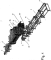
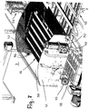
- the system described below is used to produce slabs from wooden slats.
- the system has a feed unit 1, by means of which the lamellae are fed to a transverse transport unit 2.
- the transverse transport unit 2 conveys the lamellae one after the other to a deflection unit 3 with which the lamellae are fed transversely to their longitudinal direction to a pressing unit 4.
- the slats provided in the transverse transport unit with their transport on a longitudinal side with glue are compressed in the pressing unit 4 adjacent to each other to form disc packs. They are sawed in a saw unit 5 after exiting the pressing unit 4 in individual plates.
- the sawed plates reach a removal unit 6, from which they are removed and fed to a further use.
- a plate consisting of the slats is shown. It consists of slats of different quality. It is essential that the lying on the two outer sides of the plate slats A are free of knots. The lying between these outer plates A inner plates B and C may have errors.
- the slats B have a plate width corresponding length.
- the slats C are shorter than the plate width.
- the slats C are connected to one another via a finger joint. All lamellae A to C are glued together at their abutment surfaces.
- the one outer disk A and the inner disks B and C each have a width b.
- These slats can be either the same width or different widths.
- the slat width b can be, for example, in the range between 30 mm and 70 mm.
- the other outer fin A has a much smaller width ba.
- the minimum size of this width ba is, for example, 15 mm.
- the plate width PB may be, for example, between 100 mm and 1200 mm. Since the slabs must be sawn from the slat carpet, the slats must be recorded in terms of their width and quality in the system. In addition, these lamellae must be put together in a manner to be described and cut in the saw unit 5 to the plates so that the plates have the knot-free lamellae A on both its outer sides.
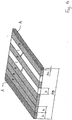
- the lamella carpet is shown from which the individual lamellar plates are sawn.
- the lamellae A to C are arranged so that the lamella carpet is divided by way of example into the lamellar plates with the widths PB1 and PB2 with the saw, characterized by the saw blades SB.
- the branch-free lamellae A In the area of the kerf, the branch-free lamellae A must be located, so that it is ensured that after the saw cut, the resulting lamellar plates are provided on their outer sides with the knot-free lamellae A.
- the plate width PB may be, for example, between 100 mm and 1200 mm.
- the total length of the lamellar carpet is designated MPB (multiplate width), which may be, for example, between 2,000 mm and 50,000 mm. After the saw cut remains only a small piece of waste with the width RB.
- MPB multiplate width
- the lamellae can be arranged within the lamellar carpet in such a way that there is a knot-free lamella A at the sawing cut-offs and that the remaining piece is as narrow as possible, so that the waste is small.
- the plates are each formed of three different slats A to C. Possible that the lamellar plates only consist of two lamella types. It is only essential that the two outside slats A are free of knots.
- the fins are denoted by 7, with A and B indicating their quality.
- the quality A refers to slats 7, which are knot-free.
- Slats 7 of quality B may have branches or other defects.
- the wooden slats 7 can be supplied at the end of the task 8 designed as a longitudinal transport unit feed unit 1 by hand.
- the slats 7 to be processed are stacked on pallets and are placed on the feed unit 1 at the end of loading 8 by means of a handling unit (not shown).
- the handling unit is provided with at least one suction box, with which the adjacent slats can be received as a unit and placed on the feed unit 1.
- This suction box extends transversely, preferably perpendicular to the longitudinal direction of the slats 7, so that they can be easily lifted from the stack and placed on the feed unit 1.
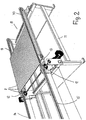
- the conveyor belt 10 has two mutually parallel, endlessly circulating conveyor belts 9, 10, which are provided on a frame 11 and whose distance can be adjusted to adapt to different long slats 7.
- the conveyor belt 10 is moved relative to the conveyor belt 9 on the frame 11.
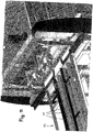
- the slat position is aligned at its front in the direction of transport edge by stop finger 12 at right angles to the transport direction. They are mounted pivotably about a horizontal axis 13 on the frame 11.
- stop position Fig. 2
- the slats 7 strike with their on the conveyor belts 9, 10 laterally projecting ends of the stop fingers 12 at.
- the stop fingers 12 are pivoted about the axes 13 downwards, whereby the slats are released. They are transported by the conveyor belts 9, 10 on conveyor belts 14, 15, whose upper run at the same height with the upper run of the conveyor belts 9, 10 lies. This ensures a continuous transition of the slats 7 of the conveyor belts 9, 10 on the conveyor belts 14, 15.
- the conveyor belts 14, 15 are driven at a higher speed than the conveyor belts 9, 10. In the transfer area, the conveyor belts 9, 10 and 14, 15 overlap one another in the transport direction. This ensures that the respective blade 7, as soon as it passes in this transfer area on the conveyor belts 14, 15, is transported at a higher speed than the subsequent slat 7, which is still on the slower moving conveyor belts 9, 10. As a result, the lamellae 7 are pulled apart, so that they no longer abut each other with their longitudinal sides, but are spaced from each other ( Fig. 3 ). Depending on the speed of the conveyor belts 14, 15, the slats 7 are pulled apart, for example, to a distance of about 20 to 25 mm.
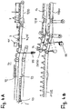
- the slats 7 are under a counting or width measuring device 101 ( Fig. 4A ). Due to the distance between the slats 7, the slats can be reliably detected individually. In particular, the width of the slats 7 can be detected. The spacing formation also ensures reliable counting of the lamellae.
- the data acquired by the measuring device are stored and used for the production of the plate packs in the further course.
- the disk packs placed on the conveyor belts 9, 10 have the same quality A or B.
- the in Fig. 2 For example, the disk pack shown has slats of quality A.
- the next disk pack to be laid onto the conveyor belts 9, 10 then has, for example, the quality B.
- the quality of the slats of the individual disk packs is detected and stored by the measuring device. This makes it possible, in the further transport of the slats through the system, the slats arranged one behind the other so that the saw cut the disk packs are separated so that the resulting slat plates on their outer pages each have a lamella of quality A.
- the measurement is very easy because on the conveyor belts 14, 15, the fins have a sufficiently large distance from each other.
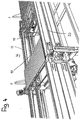
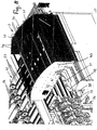
- the fins 7 then reach a floor conveyor 16, which has two spaced superimposed transport paths for the slats.
- the two transport paths are each formed by a transport unit 17, 18 and 19, 20, which are formed by endless circulating conveyor belts.
- the conveyor belts 14, 15 facing the end of the floor conveyor 16 is formed by two switches formed as a swing points 21, 22; 23, 24 are formed, each with an endless circulating transport element 25, 26; 27, 28 are provided in the form of conveyor belts.
- the switches 21 to 24 are adjusted together so that the blades 7 reach either the lower transport unit 19, 20 or the upper transport unit 17, 18.
- the slats 7 of a quality A for example, reach the lower and the slats 7 of quality B on the upper transport unit 19, 20 and 17, 18.
- the switches 21 to 24 are pivoted upwards.
- the drive elements 27, 28 of the lower turnouts 23, 24 adjoin the conveyor belts 14, 15.
- the slats 7 of quality A are thereby supplied via the lower points 23, 24 of the lower transport unit 19, 20. If the disk set has the slats 7 of quality B, the points are swung down in the example, so that the drive elements 25, 26 of the upper points 21, 22 take the slats 7 with the quality B of the conveyor belts 14, 15 and up to the Transport units 17, 18 of the floor conveyor 16 transport.
- the distance between the conveyor belts 14 and 15, 17 and the transport units 18, 19 and 20 or 25 and 26 is adjustable, so that an adaptation to different lengths slats 7 is possible.
- the transport units 17, 18 and 19, 20 form two independently driven conveyor areas for buffering and passing on a slat position, with slats 7 of a quality A or B lying in each conveyor area.
- the floor conveyor 16 has two such conveyor areas in the embodiment. However, it can also have at least one further conveying region, so that lamellae 7 of a further quality C can be used. But it is also possible to arrange in this case in two conveyor areas, for example, slats of quality B and in the third conveyor area slats of quality A, as for the slats much more slats of quality B are required as slats of quality A.
- FIG. 4 shows the situation that on the upper conveyor belts of the transport unit 17, 18 a slat position 7, for example, the quality B is provided and slats 7 of quality A at the beginning of the floor conveyor 16 are transported to the lower conveyor belts of the transport unit 19, 20.
- Fig. 4A shows a side view and a schematic representation that the lamellae 7 abut each other on the conveyor belts 9, 10 in the manner described and in the transfer to the conveyor belts 14, 15 are separated.
- the switches 21 to 24 of the floor conveyor 16 are pivoted so that the separated lamellae 7 reach the upper transport path 17, 18.
- the slats 7 are brought together again, so that they lie against each other with their long sides, as in Fig. 4 is shown for the located on the upper transport unit 17, 18 fins.
- These attacks can be mounted pivotally on the frame of the floor conveyor 16 similar to the stop finger 12.
- the stops are moved in the transport path of the slats 7, so that the respective foremost slat 7 runs on them.
- the floor conveyor 16 is provided at its front end in the transport direction with further, designed as swing points, of which in Fig. 1 the upper switches 29, 30 can be seen.
- the switches provided at this end are of the same design as the switches 21 to 24. Like the switches 21 to 24, they are advantageously pivoted simultaneously by a common drive. With the help of the directional points in the direction of transport, it is possible to transport the slats 7 to a transport unit 31, 32, with which the slats of the transverse transport unit 2 are supplied.
- the transport unit 31, 32 is formed by endless circulating conveyor belts ( Fig. 1 ), on which the slats 7 of the transverse transport unit 2 are supplied.
- the switches are pivoted into the corresponding position, so that the slats 7 are transported by the lower or the upper transport unit to the transport unit 31, 32.
- the switches 29, 30 are pivoted so that the lower transport unit 19, 20 is connected to the transport unit 31, 32.
- This has the consequence that the slats 7 of the lower transport unit 19, 20 of the floor conveyor 16 reach the lower points, where they are separated again.
- the conveyor belts of the lower points have a higher transport speed than The conveyor belts of the transport unit 19, 20 of the floor conveyor 16.
- the conveyor belts of the transport unit 17/18 are driven by servomotors.
- the slats 7 can be transported in the desired number on the switches.
- the or the other turnouts reach to corresponding stop stops 94.
- these switches can already be filled with a corresponding number of slats 7, while the slats extend the active switch. This gives a very high throughput.
- the slats 7 of the quality A and the quality B in the required order on the conveyor belts of the transport unit 31, 32 promoted.
- the lamellae 7 of quality A are located at the places where later in the saw unit 5, the lamellar carpet is divided into the individual lamella plates.
- the lamellae 7 can be measured again in the area of the points 29, 30 with respect to their width and / or their quality.
- the results are input to the controller, which passes signals to the saw unit 5, so that the lamellar carpet is divided at the desired location.
- FIGS. 4A and 4B exemplary drives for the switches 21 to 24, 29 and 30 are shown.
- the drive 95 is pivotally mounted on the frame.
- Fig. 4B shows as a further possibility a drive 95, which is designed in the manner of a crank mechanism. Even with such a drive, the switches can be pivoted in a structurally simple way up and down.
- Fig. 4C shows an example of a floor conveyor, which consists of three superposed transport paths.
- the middle transport path is aligned with the conveyor belts of the transport unit 31, 32.
- the upper and lower conveyor belts can be connected to the switches with the conveyor belts of the transport unit 31, 32.
- the drive elements 25, 26; 27, 28 of the switches 21 to 24, 29, 30 are advantageously driven by servomotors.
- the switches 29, 30 programmatically program the respectively correct number of lamellae 7.
- the conveyor belts of the switches 21 to 24, 29, 30 are driven independently. This makes it possible, for example, that slats 7 are conveyed out of the floor conveyor 16 by one switch 29, 30 onto the transport unit 31, 32, while the next slats 7 are clocked into the other switch 29, 30.
- the slats 7 are transported with the conveyor belts of the transport unit 31, 32 against a stop 33, which is part of the transverse transport unit 2.
- the stopper 33 is formed, for example, by a rail which extends in the longitudinal direction of the lamellae 7.
- the stop 33 is adjustable in height so that it can be adjusted from the movement path of the slats 7 upwards. Through the stop 33, the slats 7 reach with their long sides for mutual contact.
- a side guide 34 which is formed by rollers rotatable about vertical axes, which are arranged in a row at a distance one behind the other.
- the front in each case in the transport direction slat 7 runs at a raised stop 33rd on.
- a driver 91 ( Fig. 5 and 6 ), which is moved in the transport direction of the transverse transport unit 2 accelerated. It is moved by a drive (not shown) at high speed against the end face of each of its longitudinal side against the rollers of the side guide 34 lamella, which is transported by the driver 91 in its longitudinal direction in the direction of the deflection unit 3.
- the rollers of the side guide 34 are advantageously provided with a friction lining 35 in order to be able to reliably transport the lamellae 7 in their longitudinal direction.
- the slats 7 are transported one by one along the rollers with the driver 91 in its longitudinal direction.
- each lamella During their longitudinal transport, glue is applied to one longitudinal side of each lamella.
- glue application unit 36 which has at least one application head. With him glue is continuously applied to the one longitudinal side of the blade 7 in its longitudinal transport from the transverse transport unit 2 to the deflection unit 3.
- the lamellae 7 are arranged between rows of drive rollers 37 (FIG. Fig. 8 ), which are each rotatably driven about horizontal axes.
- the drive rollers 37 are located on the
- the drive rollers 37 detect the sliders 7 supplied by the driver 91 and accelerate them. The slats 7 are thereby removed from the driver 91 so that it can be moved back to the starting position in order to supply the next slat 7 to the drive rollers 37.
- To the series of drive rollers 37 includes an endless circulating wide conveyor belt 38 on which the acted upon on a longitudinal side with glue fins 7 are transported into the deflection unit 3.
- the fins 7 lie with their broad sides on the conveyor belt 38. It extends beyond both ends of a housing 39 of the deflection unit ( Fig. 7 and 8th ).
- a housing 39 of the deflection unit Fig. 7 and 8th .
- In the side walls 40, 41 of the housing 39 are each an inlet opening 42 and an outlet opening 43. Both openings 42, 43 have rectangular outline in the embodiment.
- the conveyor belt 38 extends through the openings 42, 43.
- a conveyor unit 44 is housed, with which the slats are transported perpendicular to their longitudinal direction to a transport unit 45, with which the slats 7 of the pressing unit 4 are supplied.
- the conveyor unit 44 has at a distance one behind the other sliding strips 46 which are mounted near its two ends standing on endlessly circulating belts 47.
- the endless circulating belts 47 are provided adjacent to the inner sides of the housing side walls 40, 41.
- the one pulleys sit on a shaft 49 which projects beyond the housing side wall 41.
- a drive motor 50 is fixed, with which the shaft 49 is driven.
- the other end of the shaft 49 is advantageously mounted in the housing side wall 40.
- the distance between adjacent slide bars 46 is slightly larger than the width of the slats 7 to be transported, by means of the conveyor belt 38 between two sliding strips 46th
- a guide bar 51 is connected, which initially extends against the transport direction of the slats 7 and the free end 52 is angled obliquely outwards. This angled end 52 ensures that the fins 7, if they are not accurately fed, are moved to the correct position upon impact with this angled end 52 when the fins enter the housing 39 through the inlet opening 42.
- the housing 39 is a (not shown) stop on which the slats 7 impinge with their front in the transport direction end face. In this way, the slats 7 are aligned accurately.
- the conveyor belt 38 has a much lower speed than the drive rollers 37 and is substantially wider than the distance between adjacent slide bars 46. This leaves the slats 7 via several transverse contacts on the conveyor belt 38 and can be fully aligned with the stop.
- the complete deflecting unit 3 can be displaced in the transport direction of the slats 7. This ensures that the lamellae 7 are supplied regardless of their length exactly center of the press unit 4.
- the drive motor 50 is turned on and the endless circulating conveyor belts 47 are moved so that the slide bars 46, the slats 7 in Fig. 8 slide to the left in the direction of the transport unit 45. It is advantageously monitored with sensors that the lamellae 7 completely between adjacent
- the transport direction of the transport unit 45 lies parallel to the transport direction of the feed unit 1 as well as perpendicular to the transport direction of the transverse transport unit 2. Since the transport unit 45 has a plurality of narrow transport elements 53, the lamellae can be properly supported irrespective of their length and fed to the pressing unit 4.
- the slats resting on the transport elements 53 pass under upper transport elements 54 in the form of endlessly circulating conveyor belts, which lie opposite the transport elements 53 at a distance.
- the distance between the superimposed transport elements 53, 54 corresponds approximately to the thickness of the lamellae 7, which are transported transversely to their longitudinal direction.
- the transport unit 45 has in a simple embodiment, only two spaced apart transport elements 53. If more than two transport elements are provided, then the transport elements which are not required for the transport of the lamellae 7 are advantageously lowered. This ensures that the lamellae 7, regardless of their length always only two
- Transport elements 53 rest. In this way, adaptation to different length slats 7 is possible.
- the upper transport elements 54 are designed and arranged such that the lamellae 7 are initially only guided and only slightly pressed down in the further transport path. This also ensures that the respective front fins are braked slightly so that the subsequent fins connect to the respective front fins and form in this way a continuous lamellar carpet.
- the lamellae 7 lie with their treated with glue longitudinal sides together.
- These transport elements 54 can optionally be lowered, so that the lamellae 7 always rest only on two transport elements 54.
- a monitoring unit that monitors the orientation of the adjacent slats.
- This monitoring unit advantageously has a laser photocell pair with which the lamellar alignment can be reliably monitored. If the monitoring results in a misalignment of the lamellae, advantageously an additional alignment unit 87 can be switched on, with which the lamellae between the transport elements 53, 54 can be aligned accordingly. It is possible that further sensors, for example pairs of photocells, are provided which monitor this readjustment and if necessary stop the pressing unit 4.
- the additional alignment unit 87 is designed as a pivoting unit and has a pivotable about a vertical axis pivot arm 88 (FIG. Fig. 9 ), the one with
- the adjusting device 89 can be pivoted.
- the adjusting device 89 is advantageously formed by a hydraulic piston-cylinder unit.
- the band 90 projects laterally beyond the pivoting arm 88.
- the additional alignment unit 87 is located laterally next to the transport unit 45. If adjacent lamellae 7 are not aligned exactly with one another, then the additional alignment unit 87 is switched on by the monitoring unit. It is pivoted about the vertical axis in the direction of the transport unit 45. The pivot arm 88 comes with the band 90 near its free end with the side over the transport unit 45 projecting ends of the slats 7 into contact and aligns them against each other. The belt 90 is driven in such a way that it does not affect the transport of the lamellae 7 in the direction of the pressing unit 4.
- At the additional alignment unit 87 opposite side can be provided for the slats 7 in the transport direction extending longitudinal stop.
- Fig. 9A shows that at least one adjustable sliding carriage 96 is provided as a stop in the region of the transport unit 45. It can be adjusted in the transport direction and perpendicular thereto.
- the sliding carriage 96 has a rake-shaped stop 97 which is adjustable in the height direction in the transport path of the slats 7. It is then moved upwards into the stop position when the lamellar carpet transported into the press unit 4 has the intended length. Then, the following slats 7 are stopped in the area of the transport unit 45. This has the consequence that the first with Distance one behind the other slats accumulate on each other and abut each other with their long sides.
- plate chains are provided as feed 98, which form adjacent chain tracks and with which the plate carpet is transported further ( Fig. 9A ).
- the lower plate chains 99 run on Gleit Equipmentsangn and form an exact support surface for the Lamelleneppich.
- the upper plate chains are pressed onto the top of the lamellar carpet.
- printing elements 100 are provided, which close to each other seamlessly and are acted upon by pressure hoses.
- the pressure hoses are pressurized medium, preferably compressed air, and thereby stretched elastically. The pressure is transferred to the printing elements which press on the plates of the plate chains.
- the pressure exerted by the plate chains on the slats pressure force is so high that thickness tolerances of the slats 7 are compensated by plastic deformation of the slats.
- Proportional valves are advantageously used, with which the pressure in the pressure hoses can be set exactly.
- six chain tracks are arranged side by side, which are each driven by a servomotor.
- the servomotors are coupled with each other via an electric gearbox and therefore run absolutely the same. But it is also possible to drive the servo motors independently. This makes it possible to align by obliquely fast drive an obliquely running plate pack again.
- the upper and lower plate chains of the feeds 98, 99 are advantageously divided into two parts, which are acted upon individually by means of the pressure elements.
- This division also has the advantage that the effective, acting on the lamella carpet feed force for both halves of the lamellar carpet can be controlled independently.
- the chain tracks are also provided with separate drive shafts.
- the drives of the various drive shafts are again advantageously synchronized.
- a lower table support forms a negative pole of the high-frequency heating and an upper pressure or hold-down plate forms a positive pole of the high-frequency heating.
- the used for this purpose brake unit has a mounted on linear guides frame, which is pressed by the force exerted on the lamella carpet chain feed force against pressure gauge, preferably pressure cells.
- the amount of feed force determines the pressure acting on the glue joints between the slats 7 pressing pressure, which can be reliably monitored by means of the pressure transducer.
- the pressure hose extending transversely to the transport direction of the lamellar carpet in the press unit 4 is advantageously divided in the middle and is actuated on the right and left independently of two proportional valves. For smaller widths of the lamellar carpet is also sufficient a single continuous pressure hose.
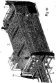
- the transport unit 56 advantageously has a plurality of endlessly circulating transport belts 57, which are arranged parallel to each other at a distance. They extend to the saw unit 5, which is provided with a transport unit 58. It also has a plurality of spaced apart, endless, circulating transport belt 59. The lamellar carpet is taken over by the transport unit 58.
- the saw unit 5 has two sawing stations 60, 61 which operate independently of each other. With them, it is possible to divide a slat carpet simultaneously in two plates.
- the two sawing stations 60, 61 each have a portal 62, 63, which projects beyond the transport belts 59.
- Each gantry 62, 63 has an upper cross member 64, 65 which supports the vertical columns 66, 67; 68, 69 at the top connects.
- 65 At a distance below the upper cross member 64, 65 is another cross member 70, 71 which extends between the two columns 66, 67; 68, 69 extends and in each case with a longitudinally extending slot 72, 73 is provided. Through the slots 72, 73 each project a circular saw blade 74, 75 of a circular saw 76, 77.
- the circular saw 76, 77 is movable along the upper cross member 70, 71.
- the circular saws 76, 77 are provided on a carriage 78, 79 which is slidably guided on the upper cross member 64, 65. The circular saws 76, 77 can be moved along the carriage 78, 79 in the height direction.
- the two circular saws 76, 77 are arranged at two opposite ends of the two sawing stations 60, 61 in the initial position (FIG. Fig. 12 ).
- the circular saw 76, 77 is moved in this initial position in the upper end position.
- the circular saw 76, 77 is moved along the carriage 78, 79 in the lower end position in which the circular saw blade 74, 75 protrudes through the longitudinal slot 72, 73 in the lower cross member 70, 71.
- the sawing station 61 is provided stationary in the system, while the sawing station 60 can advantageously be adjusted in the transport direction of the lamellar carpet ( Fig. 12A ). This makes it possible to adjust the distance between the circular saw blades 74, 75 of the two sawing stations 60, 61. As a result, the width PB2 of the slat plate to be produced can be adjusted.
- the adjustment path of the sawing station 60 is 1,200 mm.
- the transport unit 58 of the saw unit 5 is provided with front stops 80 in the transport direction, which are located between adjacent transport belts 59 of the transport unit 56 and can be moved upwards from a lowered position into a stop position.
- the stops 80 are adjusted upward as soon as a lamellar carpet enters the saw unit 5.
- the saw cut is made with the two circular saws 76, 77.
- two plates are simultaneously sawn from the lamellar carpet.
- the stops 80 which determine the position of the lamellar carpet during the sawing process, are in the transport direction of the lamellar carpet in front of the sawing station 61.
- the stops 80 are advantageously housed in a carrier 81 which extends perpendicular to the transport direction of the table tops or lamellar carpets and from the the stops 80 protrude upwards. They are pushed upwards out of the carrier 81 if they are to assume their stop position.
- the stops 80 can be adjusted in the transport direction, so as to set the distance between the stops 80 and the circular saw blade 75 of the sawing station 61 in this way. As it turned out Fig. 12A can, therefore, can the width PB of the lamella plate can be adjusted.
- the displacement of the stop 80 in the conveying direction of the lamella plate is 1300 mm.
- the plates can have the same width but also different widths.
- the lamination plate to be produced by means of the circular saw blade 75 of the sawing station 61 has the width PB1 which is substantially larger than the width PB2 of the second louver plate.
- a slat 7 of the quality A as based on the Fig. 14 and 15 has been explained.
- the foremost lamella in the transport direction of the lamellar carpet is definitely a slat with the quality A, because the slat carpet is not sawn at this front end.
- the slat carpet performs no unwanted movements during the sawing process, it is clamped during the sawing process.
- supports 82 (FIG. Fig. 12 ), which extend from the transport unit 56 into the transport unit 58 and extend approximately to the level of the first saw station 60.
- the pads 82 are moved upwards prior to the sawing operation, whereby the lamellar carpet is raised.
- the cross member 70, 71 is placed from above on the lamella carpet. It serves as a pressure rail in this case, which presses the laminate carpet against the raised supports 82.
- the lamellar carpet is clamped during the statgevorganges between the raised supports and the cross members 71, 72.
- the sawed plates are transported by the transport unit 58 onto the removal unit 6.
- the stops 80 are first lowered for this purpose, so that after switching on the conveyor belt 59 sawed off
- the Abtransportiser 6 has a plurality of parallel adjacent to each other endlessly circulating conveyor belt 83 ( Fig. 13 ), which take over the sawed plates.
- the removal unit 6 is provided with pivoting arms 84 which each have at least one endlessly circulating transport belt 84 '.
- the pivot arms 84 are advantageously non-rotatably mounted on a common shaft 85, which extends perpendicular to the transport direction of the Abtransportiser 6 and can be actuated by means of a drive motor 86 for adjusting the pivot arms 84.
- the pivot arms 84 are designed as a one-armed lever and extend with its free end in the region between the transport belt 59 of the transport unit 58th
- the pivot arms 84 When the sawn plates are transported to the removal unit 6, the pivot arms 84 are in a lower, horizontal position, in which the upper run of the transport belts 84 'lie in a plane with the upper run of the transport belts 59, 83.
- the pivot arms 84 from the horizontal position upward in the in Fig. 13 pivoted position pivoted.
- the waste piece transported by means of the transport belts 59 then falls downwards at the end of the transport unit 58, for example into a collecting container.
- the pivot arms 84 After sorting out the piece of waste, the pivot arms 84 are pivoted back into their horizontal position, so that the subsequent sawed plates reach the conveyor belts 83 of the removal unit 6.
- the handling device advantageously has a suction box, which is provided on a gripper arm and with which the plates can be easily lifted from the Abtransportü 6.
- the Abtransportiser 6 is advantageously provided with (not shown) stops, to which the supplied
- the plant described is characterized by the fact that plates made from lamellae can be produced with very high cycle performance.
- the floor conveyor 16 and the two sawing stations 60, 61 contribute in a particularly advantageous manner.
- the sawing station 60 located in the transport direction of the lamellar carpet can advantageously be arranged to be adjustable in the transport direction, so that the width of the second plate varies depending on the position of the sawing station 60 can be.
- the sawing station 61 is arranged stationary and thereby occupies a predetermined distance from the stops 80. As a result, the first, sawn from the slat carpet plate has a predetermined width.
- the saw unit 5 and the Abtransportwent 6 lie on the one and the feed unit 1 on the other side of the press unit 4. It is also possible in principle that the saw unit 5 and the Abtransportwent 6 are arranged on the same side of the press unit 4 as the feed unit 1. In such a case, the saw unit 5 and the Abtransportwent 6 are adjacent to the feed unit. 1
- the various transport units may instead of the described conveyor belts or belts also have other transport elements with which the individual slats or the slat carpet or the sawed plates can be reliably transported.
Landscapes
- Life Sciences & Earth Sciences (AREA)
- Engineering & Computer Science (AREA)
- Mechanical Engineering (AREA)
- Wood Science & Technology (AREA)
- Forests & Forestry (AREA)
- Veneer Processing And Manufacture Of Plywood (AREA)
- Dry Formation Of Fiberboard And The Like (AREA)
- Making Paper Articles (AREA)
Claims (9)
- Installation de fabrication de plaques en lamelles (7) de bois, avec au moins une unité d'alimentation (1), à l'aide de laquelle les lamelles (7) sont transportables dans l'installation, avec au moins une unité d'encollage (36) prévue pour appliquer de la colle sur au moins un côté longitudinal des lamelles (7), avec au moins une unité de pressage (4) prévue pour comprimer des lamelles (7) adjacentes par leurs côtés longitudinaux et avec au moins un convoyeur à étages (16) qui comporte au moins deux unités de transport (17, 18 ; 19, 20) différentes, superposées avec un écart, qui dans la zone d'entrée du convoyeur à étages (16) comportent chacune un aiguillage (21 à 24) qui est réglable pour reprendre les lamelles (7) à partir de l'unité d'alimentation (1) qui comporte des bandes transporteuses (9, 10 ; 14, 15) en rotation continue pour l'alimentation des lamelles (7) vers le convoyeur à étages (16),selon lequel le convoyeur à étages (16) étant prévu dans le trajet de transport vers l'unité d'encollage (36) et
caractérisée en ce que les aiguillages (21 à 24) sont réglables ensemble de telle sorte que dans l'une des positions, les aiguillages (23, 24) inférieurs transportent les lamelles (7) des bandes transporteuses (14, 15) de l'unité d'alimentation (1) sur l'unité de transport (19, 20) inférieure et dans l'autre position, les aiguillages (21, 22) supérieurs transportent les lamelles (7) des bandes transporteuses (14, 15) de l'unité d'alimentation (1) sur l'unité de transport (17, 18) supérieure du convoyeur à étages (16) et en e que les aiguillages (21 à 24) comportent des éléments d'entraînement (25 à 28) conçus en rotation continue pour les lamelles (7) qui sont entraînés indépendamment les uns des autres. - Installation selon la revendication 1,
caractérisée en ce que le convoyeur à étages (16) se raccorde sur au moins une unité de transport (31, 32) montée en aval, qui est montée en amont d'une unité de transport (2) transversale pour les lamelles (7) qui comporte un guidage latéral (34) pour les lamelles (7). - Installation selon la revendication 2,
caractérisée en ce que le guidage latéral (34) est formé par des galets rotatifs autour d'un axe vertical, placés côte à côte en rangée. - Installation selon la revendication 2 ou la revendication 3,
caractérisée en ce que les lamelles (7) alimentées vers l'unité d'encollage (36) sont transportées successivement, une à une dans leur direction longitudinale le long du guidage latéral (34) par au moins un entraîneur (91). - Installation selon la revendication 4,
caractérisée en ce que dans la région de l'unité d'encollage (36), les lamelles (7) sont transportables entre des galets d'entraînement (37) entraînés en rotation, qui saisissent les lamelles (7) sur la face supérieure et la face inférieure. - Installation selon l'une quelconque des revendications 1 à 5,
caractérisée en ce que dans la région de sortie des unités de transport (17, 18 ; 19, 20), le convoyeur à étages (16) comporte des aiguillages supplémentaires (29, 30) qui comportent des éléments d'entraînement (25 à 28) conçus en rotation continue pour les lamelles (7), qui sont entraînés indépendamment les uns des autres. - Installation selon la revendication 6,
caractérisée en ce que les aiguillages (29, 30) dans la région de sorte du convoyeur à étages (16) sont réglables de telle sorte que les lamelles (7) soient transportables de l'unité de transport (17, 18 ; 19, 20) inférieure et supérieure sur l'unité de transport (31, 32) montée en aval. - Installation selon l'une quelconque des revendications 1 à 7,
caractérisée en ce que l'écart entre les aiguillages (21 à 23 ; 29, 30) placés côte à côte est réglable pour s'adapter à la longueur actuelle des lamelles (7). - Procédé destiné à la fabrication de plaques en lamelles (7) de bois en utilisant une installation selon l'une quelconque des revendications 1 à 8, lors duquel on alimente les lamelles (7) vers une unité d'encollage (36) dans laquelle elles reçoivent de la colle sur au moins un côté longitudinal, lors duquel on assemble les lamelles (7) encollées en un paquet de lamelles et on les comprime par la suite, lors de leur alimentation vers l'unité d'encollage (36), les lamelles (7) pouvant être distribuées sur au moins deux trajets de transport, par commande programmée, les lamelles (7) étant prélevées dans les trajets de transport de telle sorte qu'à l'intérieur du paquet de lamelles qui doit être créé, les lamelles (7) soient placées les unes derrière les autres selon un ordre chronologique prédéfini au niveau de leur qualité,
caractérisé en ce que lors de l'introduction via l'unité d'alimentation (1), les largeurs des lamelles sont détectées à l'aide d'une mesure de la largeur, en ce que les lamelles ainsi détectées sont assemblées de telle sorte que sur une plaque à largeur multiple (MPB), le reste résiduel soit le plus restreint possible et en ce que l'apparence des plaques individuelles est assemblée de telle sorte qu'à l'intérieur se trouvent les qualités souhaitées des lamelles (B et le cas échéant, C) et sur le bord, soit toujours placée une lamelle de qualité supérieure (A).
Applications Claiming Priority (1)
| Application Number | Priority Date | Filing Date | Title |
|---|---|---|---|
| DE102009019512A DE102009019512A1 (de) | 2009-04-24 | 2009-04-24 | Anlage zur Herstellung von Platten aus Lamellen aus Holz sowie Verfahren zur Herstellung solcher Platten |
Publications (3)
| Publication Number | Publication Date |
|---|---|
| EP2243606A2 EP2243606A2 (fr) | 2010-10-27 |
| EP2243606A3 EP2243606A3 (fr) | 2011-11-09 |
| EP2243606B1 true EP2243606B1 (fr) | 2017-02-22 |
Family
ID=42557352
Family Applications (1)
| Application Number | Title | Priority Date | Filing Date |
|---|---|---|---|
| EP10004183.9A Active EP2243606B1 (fr) | 2009-04-24 | 2010-04-20 | Installation de fabrication de plaques en lamelles de bois et procédé destiné à la fabrication de telles plaques |
Country Status (3)
| Country | Link |
|---|---|
| EP (1) | EP2243606B1 (fr) |
| DE (1) | DE102009019512A1 (fr) |
| DK (1) | DK2243606T3 (fr) |
Families Citing this family (10)
| Publication number | Priority date | Publication date | Assignee | Title |
|---|---|---|---|---|
| DE102014208872A1 (de) * | 2014-05-12 | 2015-11-12 | Homag Holzbearbeitungssysteme Gmbh | Bearbeitungsvorrichtung und Bearbeitungsverfahren |
| CN104071560B (zh) * | 2014-06-22 | 2016-03-30 | 薛炎 | 换热器芯体集成机组的翅片垂直翻转装置 |
| CN105196374B (zh) * | 2015-09-09 | 2017-06-30 | 郑胜火 | 一种自动拼板机及拼板方法 |
| CN107009449B (zh) * | 2017-04-24 | 2018-12-25 | 泉州市盛国贸易有限公司 | 一种板材的自动旋转式压合装置 |
| CN106985224B (zh) * | 2017-04-24 | 2018-12-25 | 泉州市巨作贸易有限公司 | 一种板材的相对平移压合装置 |
| CN110281324B (zh) * | 2019-06-14 | 2024-03-26 | 永安市亚林竹类研究所有限公司 | 一种板材接长系统 |
| CN114454268A (zh) * | 2022-02-09 | 2022-05-10 | 黄骏锋 | 一种胶合板粘合定型设备 |
| CN115229915B (zh) * | 2022-08-31 | 2023-08-08 | 福建义精科技有限公司 | 一种用于板材加工成型的装置及工艺方法 |
| AT526066B1 (de) * | 2022-09-09 | 2023-11-15 | Fill Gmbh | Holzlamellenhandlinganlage, sowie ein Verfahren zum Betreiben der Holzlamellenhandlinganlage |
| CN117485014B (zh) * | 2023-12-29 | 2024-04-09 | 江苏欧圣新材料有限公司 | 一种抗菌生物质地板静音垫覆膜机及工艺 |
Citations (11)
| Publication number | Priority date | Publication date | Assignee | Title |
|---|---|---|---|---|
| US2490819A (en) | 1947-06-02 | 1949-12-13 | Tennessee Valley Authority | Making laminated lumber |
| US3723230A (en) | 1970-10-12 | 1973-03-27 | Trus Joist Corp | Continuous press for pressing gluecoated consolidatable press charges |
| US4356045A (en) * | 1980-05-30 | 1982-10-26 | St. Regis Paper Company | Complete production line of wood I-joist manufacturing apparatus the method of manufacture, and the I-joist product, having lumber chords and a plywood web |
| US4934228A (en) | 1989-01-13 | 1990-06-19 | U.S. Natural Resources, Inc. | System for diverting veneer sheets having offsize defects |
| EP0376918A2 (fr) | 1988-12-30 | 1990-07-04 | Gebr. Linck Maschinenfabrik "Gatterlinck" GmbH & Co. KG | Méthode et dispositif pour produire des lamelles de bois à partir de bois de charpente |
| WO1992005020A1 (fr) | 1990-09-20 | 1992-04-02 | Gebrüder Linck Maschinenfabrik 'gatterlinck' Gmbh & Co. Kg | Dispositif de decoupage de lamelles de bois sans enlevement de copeaux a partir d'une piece de bois d'equarrissage |
| EP0732180A2 (fr) | 1995-03-17 | 1996-09-18 | Gebrüder Linck, Maschinenfabrik "Gatterlinck" GmbH & Co.KG | Procédé pour tranches des planches minces, en particulier des lamelles de parquet |
| EP0995681A1 (fr) | 1998-10-06 | 2000-04-26 | Fort James France | Unité de fabrication et d'emballage de produits en rouleaux |
| WO2005021410A1 (fr) * | 2003-08-29 | 2005-03-10 | Vanderlande Industries Nederland B.V. | Transporteur comportant deux transporteurs de chargement et deux transporteurs de dechargement relies par des moyens de transfert |
| EP2078598A2 (fr) | 2008-01-11 | 2009-07-15 | Springer Maschinenfabrik AG | Procédé et dispositif de traitement d'assemblages avec dents collées |
| WO2009124544A1 (fr) | 2008-04-09 | 2009-10-15 | jöma GmbH | Dispositif convoyeur pour installation d'aboutage par entures multiples de pièces de bois |
-
2009
- 2009-04-24 DE DE102009019512A patent/DE102009019512A1/de not_active Withdrawn
-
2010
- 2010-04-20 DK DK10004183.9T patent/DK2243606T3/da active
- 2010-04-20 EP EP10004183.9A patent/EP2243606B1/fr active Active
Patent Citations (12)
| Publication number | Priority date | Publication date | Assignee | Title |
|---|---|---|---|---|
| US2490819A (en) | 1947-06-02 | 1949-12-13 | Tennessee Valley Authority | Making laminated lumber |
| US3723230A (en) | 1970-10-12 | 1973-03-27 | Trus Joist Corp | Continuous press for pressing gluecoated consolidatable press charges |
| US4356045A (en) * | 1980-05-30 | 1982-10-26 | St. Regis Paper Company | Complete production line of wood I-joist manufacturing apparatus the method of manufacture, and the I-joist product, having lumber chords and a plywood web |
| EP0376918A2 (fr) | 1988-12-30 | 1990-07-04 | Gebr. Linck Maschinenfabrik "Gatterlinck" GmbH & Co. KG | Méthode et dispositif pour produire des lamelles de bois à partir de bois de charpente |
| US5088533A (en) * | 1988-12-30 | 1992-02-18 | Hans Binder | Method and device for the production of wood sheets from cut wood |
| US4934228A (en) | 1989-01-13 | 1990-06-19 | U.S. Natural Resources, Inc. | System for diverting veneer sheets having offsize defects |
| WO1992005020A1 (fr) | 1990-09-20 | 1992-04-02 | Gebrüder Linck Maschinenfabrik 'gatterlinck' Gmbh & Co. Kg | Dispositif de decoupage de lamelles de bois sans enlevement de copeaux a partir d'une piece de bois d'equarrissage |
| EP0732180A2 (fr) | 1995-03-17 | 1996-09-18 | Gebrüder Linck, Maschinenfabrik "Gatterlinck" GmbH & Co.KG | Procédé pour tranches des planches minces, en particulier des lamelles de parquet |
| EP0995681A1 (fr) | 1998-10-06 | 2000-04-26 | Fort James France | Unité de fabrication et d'emballage de produits en rouleaux |
| WO2005021410A1 (fr) * | 2003-08-29 | 2005-03-10 | Vanderlande Industries Nederland B.V. | Transporteur comportant deux transporteurs de chargement et deux transporteurs de dechargement relies par des moyens de transfert |
| EP2078598A2 (fr) | 2008-01-11 | 2009-07-15 | Springer Maschinenfabrik AG | Procédé et dispositif de traitement d'assemblages avec dents collées |
| WO2009124544A1 (fr) | 2008-04-09 | 2009-10-15 | jöma GmbH | Dispositif convoyeur pour installation d'aboutage par entures multiples de pièces de bois |
Also Published As
| Publication number | Publication date |
|---|---|
| DK2243606T3 (da) | 2017-06-06 |
| DE102009019512A1 (de) | 2010-10-28 |
| EP2243606A3 (fr) | 2011-11-09 |
| EP2243606A2 (fr) | 2010-10-27 |
Similar Documents
| Publication | Publication Date | Title |
|---|---|---|
| EP2243606B1 (fr) | Installation de fabrication de plaques en lamelles de bois et procédé destiné à la fabrication de telles plaques | |
| EP0242763B1 (fr) | Dispositif pour couper des feuilles empilées | |
| EP2832507B1 (fr) | Procédé destiné et scie à panneaux horizontale au sciage de pièces à usiner | |
| DE3613315C2 (fr) | ||
| DE2745693C2 (de) | Vorrichtung zum Zuführen geschuppter Wellpappebogen zu einer Stapelvorrichtung | |
| EP1018408B1 (fr) | Guillotine pour couper des produits en feuilles empilées | |
| DE3716666C2 (de) | Plattenaufteilanlage mit einer Längssäge und einer Quersäge | |
| DE3107437C2 (fr) | ||
| DE4224010A1 (de) | Vorrichtung zum handhaben von bahn- oder bogenmaterial aus papier | |
| DE2007183A1 (de) | Verfahren und Vorrichtung zum Herstellen von maßgerechten Platten | |
| EP0453806A1 (fr) | Installation pour empiler des pièces constituées d'éléments plats séparés ou de paquets desdits éléments plats | |
| DE3107438A1 (de) | "einrichtung zum zentrierenden ausrichten von plattenfoermigen werkstuecken" | |
| EP1262290B1 (fr) | Dispositif de sciage pour panneaux en bois, en matière plastique, ou similaire | |
| EP2158070B1 (fr) | Dispositif de transport pour une installation d'aboutage par entures multiples | |
| EP3148789B1 (fr) | Dispositif et procédé pour transporter descorps de sacs tubulaires | |
| EP3369663B1 (fr) | Dispositif de bottelage pour pièces à usiner oblongues ainsi que procédé de bottelage de pièces à usiner oblongues | |
| EP3429811B1 (fr) | Procede de production de blocs formes d'assemblage de pieces de bois collees, et dispositif de mise en oeuvre du procede. | |
| DE3402497C2 (de) | Vorrichtung zum Kappen von Hölzern und zum anschließenden Bearbeiten der Holzabschnitte an den Seitenkanten | |
| AT396766B (de) | Einrichtung zum buntaufteilen von plattenförmigen werkstücken | |
| AT518387B1 (de) | Verfahren und Vorrichtung zum Herstellen von Lamellenlagen aus hintereinander aufgereihten Lamellen | |
| DE2828210A1 (de) | Vorrichtung zum vereinzeln stirnseitig keilgezinkter bretter aus einem paket und zum zusammenfuegen zu einem strang | |
| DE3338096A1 (de) | Verfahren und vorrichtung zum ablaengen von metallenen langformguetern | |
| EP1026108B1 (fr) | Procédé et dispositif pour la formation d'empilement pour matériau de coupe | |
| EP0730516B1 (fr) | Dispositif pour l'usinage de pieces de bois massives dans le sens de leur longueur | |
| EP2436623B1 (fr) | Procédé et dispositif pour enlever une rangée de piles |
Legal Events
| Date | Code | Title | Description |
|---|---|---|---|
| PUAI | Public reference made under article 153(3) epc to a published international application that has entered the european phase |
Free format text: ORIGINAL CODE: 0009012 |
|
| AK | Designated contracting states |
Kind code of ref document: A2 Designated state(s): AT BE BG CH CY CZ DE DK EE ES FI FR GB GR HR HU IE IS IT LI LT LU LV MC MK MT NL NO PL PT RO SE SI SK SM TR |
|
| AX | Request for extension of the european patent |
Extension state: AL BA ME RS |
|
| RIC1 | Information provided on ipc code assigned before grant |
Ipc: B27D 1/10 20060101ALI20110725BHEP Ipc: B65G 47/64 20060101ALI20110725BHEP Ipc: B27M 1/08 20060101AFI20110725BHEP Ipc: B27D 3/04 20060101ALI20110725BHEP |
|
| PUAL | Search report despatched |
Free format text: ORIGINAL CODE: 0009013 |
|
| AK | Designated contracting states |
Kind code of ref document: A3 Designated state(s): AT BE BG CH CY CZ DE DK EE ES FI FR GB GR HR HU IE IS IT LI LT LU LV MC MK MT NL NO PL PT RO SE SI SK SM TR |
|
| AX | Request for extension of the european patent |
Extension state: AL BA ME RS |
|
| RIC1 | Information provided on ipc code assigned before grant |
Ipc: B27D 3/04 20060101ALI20111006BHEP Ipc: B27M 1/08 20060101AFI20111006BHEP Ipc: B27D 1/10 20060101ALI20111006BHEP Ipc: B65G 47/64 20060101ALI20111006BHEP |
|
| 17P | Request for examination filed |
Effective date: 20120509 |
|
| 17Q | First examination report despatched |
Effective date: 20120703 |
|
| 17Q | First examination report despatched |
Effective date: 20120706 |
|
| GRAP | Despatch of communication of intention to grant a patent |
Free format text: ORIGINAL CODE: EPIDOSNIGR1 |
|
| INTG | Intention to grant announced |
Effective date: 20160905 |
|
| GRAS | Grant fee paid |
Free format text: ORIGINAL CODE: EPIDOSNIGR3 |
|
| GRAA | (expected) grant |
Free format text: ORIGINAL CODE: 0009210 |
|
| AK | Designated contracting states |
Kind code of ref document: B1 Designated state(s): AT BE BG CH CY CZ DE DK EE ES FI FR GB GR HR HU IE IS IT LI LT LU LV MC MK MT NL NO PL PT RO SE SI SK SM TR |
|
| REG | Reference to a national code |
Ref country code: GB Ref legal event code: FG4D Free format text: NOT ENGLISH |
|
| REG | Reference to a national code |
Ref country code: CH Ref legal event code: EP |
|
| RAP2 | Party data changed (patent owner data changed or rights of a patent transferred) |
Owner name: WEINIG DIMTER GMBH & CO. KG |
|
| REG | Reference to a national code |
Ref country code: AT Ref legal event code: REF Ref document number: 868905 Country of ref document: AT Kind code of ref document: T Effective date: 20170315 |
|
| REG | Reference to a national code |
Ref country code: IE Ref legal event code: FG4D Free format text: LANGUAGE OF EP DOCUMENT: GERMAN |
|
| REG | Reference to a national code |
Ref country code: DE Ref legal event code: R096 Ref document number: 502010013190 Country of ref document: DE |
|
| REG | Reference to a national code |
Ref country code: DK Ref legal event code: T3 Effective date: 20170601 |
|
| REG | Reference to a national code |
Ref country code: LT Ref legal event code: MG4D |
|
| REG | Reference to a national code |
Ref country code: NL Ref legal event code: MP Effective date: 20170222 |
|
| PG25 | Lapsed in a contracting state [announced via postgrant information from national office to epo] |
Ref country code: HR Free format text: LAPSE BECAUSE OF FAILURE TO SUBMIT A TRANSLATION OF THE DESCRIPTION OR TO PAY THE FEE WITHIN THE PRESCRIBED TIME-LIMIT Effective date: 20170222 Ref country code: GR Free format text: LAPSE BECAUSE OF FAILURE TO SUBMIT A TRANSLATION OF THE DESCRIPTION OR TO PAY THE FEE WITHIN THE PRESCRIBED TIME-LIMIT Effective date: 20170523 Ref country code: LT Free format text: LAPSE BECAUSE OF FAILURE TO SUBMIT A TRANSLATION OF THE DESCRIPTION OR TO PAY THE FEE WITHIN THE PRESCRIBED TIME-LIMIT Effective date: 20170222 Ref country code: NO Free format text: LAPSE BECAUSE OF FAILURE TO SUBMIT A TRANSLATION OF THE DESCRIPTION OR TO PAY THE FEE WITHIN THE PRESCRIBED TIME-LIMIT Effective date: 20170522 Ref country code: FI Free format text: LAPSE BECAUSE OF FAILURE TO SUBMIT A TRANSLATION OF THE DESCRIPTION OR TO PAY THE FEE WITHIN THE PRESCRIBED TIME-LIMIT Effective date: 20170222 |
|
| PG25 | Lapsed in a contracting state [announced via postgrant information from national office to epo] |
Ref country code: PT Free format text: LAPSE BECAUSE OF FAILURE TO SUBMIT A TRANSLATION OF THE DESCRIPTION OR TO PAY THE FEE WITHIN THE PRESCRIBED TIME-LIMIT Effective date: 20170622 Ref country code: BG Free format text: LAPSE BECAUSE OF FAILURE TO SUBMIT A TRANSLATION OF THE DESCRIPTION OR TO PAY THE FEE WITHIN THE PRESCRIBED TIME-LIMIT Effective date: 20170522 Ref country code: NL Free format text: LAPSE BECAUSE OF FAILURE TO SUBMIT A TRANSLATION OF THE DESCRIPTION OR TO PAY THE FEE WITHIN THE PRESCRIBED TIME-LIMIT Effective date: 20170222 Ref country code: ES Free format text: LAPSE BECAUSE OF FAILURE TO SUBMIT A TRANSLATION OF THE DESCRIPTION OR TO PAY THE FEE WITHIN THE PRESCRIBED TIME-LIMIT Effective date: 20170222 Ref country code: SE Free format text: LAPSE BECAUSE OF FAILURE TO SUBMIT A TRANSLATION OF THE DESCRIPTION OR TO PAY THE FEE WITHIN THE PRESCRIBED TIME-LIMIT Effective date: 20170222 Ref country code: LV Free format text: LAPSE BECAUSE OF FAILURE TO SUBMIT A TRANSLATION OF THE DESCRIPTION OR TO PAY THE FEE WITHIN THE PRESCRIBED TIME-LIMIT Effective date: 20170222 |
|
| PG25 | Lapsed in a contracting state [announced via postgrant information from national office to epo] |
Ref country code: CZ Free format text: LAPSE BECAUSE OF FAILURE TO SUBMIT A TRANSLATION OF THE DESCRIPTION OR TO PAY THE FEE WITHIN THE PRESCRIBED TIME-LIMIT Effective date: 20170222 Ref country code: SK Free format text: LAPSE BECAUSE OF FAILURE TO SUBMIT A TRANSLATION OF THE DESCRIPTION OR TO PAY THE FEE WITHIN THE PRESCRIBED TIME-LIMIT Effective date: 20170222 Ref country code: IT Free format text: LAPSE BECAUSE OF FAILURE TO SUBMIT A TRANSLATION OF THE DESCRIPTION OR TO PAY THE FEE WITHIN THE PRESCRIBED TIME-LIMIT Effective date: 20170222 Ref country code: RO Free format text: LAPSE BECAUSE OF FAILURE TO SUBMIT A TRANSLATION OF THE DESCRIPTION OR TO PAY THE FEE WITHIN THE PRESCRIBED TIME-LIMIT Effective date: 20170222 Ref country code: EE Free format text: LAPSE BECAUSE OF FAILURE TO SUBMIT A TRANSLATION OF THE DESCRIPTION OR TO PAY THE FEE WITHIN THE PRESCRIBED TIME-LIMIT Effective date: 20170222 |
|
| REG | Reference to a national code |
Ref country code: DE Ref legal event code: R026 Ref document number: 502010013190 Country of ref document: DE |
|
| PG25 | Lapsed in a contracting state [announced via postgrant information from national office to epo] |
Ref country code: PL Free format text: LAPSE BECAUSE OF FAILURE TO SUBMIT A TRANSLATION OF THE DESCRIPTION OR TO PAY THE FEE WITHIN THE PRESCRIBED TIME-LIMIT Effective date: 20170222 Ref country code: SM Free format text: LAPSE BECAUSE OF FAILURE TO SUBMIT A TRANSLATION OF THE DESCRIPTION OR TO PAY THE FEE WITHIN THE PRESCRIBED TIME-LIMIT Effective date: 20170222 |
|
| REG | Reference to a national code |
Ref country code: CH Ref legal event code: PL |
|
| PLBI | Opposition filed |
Free format text: ORIGINAL CODE: 0009260 |
|
| PLAX | Notice of opposition and request to file observation + time limit sent |
Free format text: ORIGINAL CODE: EPIDOSNOBS2 |
|
| 26 | Opposition filed |
Opponent name: FILL GESELLSCHAFT M.B.H. Effective date: 20171121 |
|
| GBPC | Gb: european patent ceased through non-payment of renewal fee |
Effective date: 20170522 |
|
| REG | Reference to a national code |
Ref country code: IE Ref legal event code: MM4A |
|
| REG | Reference to a national code |
Ref country code: FR Ref legal event code: ST Effective date: 20171229 |
|
| PG25 | Lapsed in a contracting state [announced via postgrant information from national office to epo] |
Ref country code: FR Free format text: LAPSE BECAUSE OF NON-PAYMENT OF DUE FEES Effective date: 20170502 Ref country code: MC Free format text: LAPSE BECAUSE OF FAILURE TO SUBMIT A TRANSLATION OF THE DESCRIPTION OR TO PAY THE FEE WITHIN THE PRESCRIBED TIME-LIMIT Effective date: 20170222 |
|
| PG25 | Lapsed in a contracting state [announced via postgrant information from national office to epo] |
Ref country code: CH Free format text: LAPSE BECAUSE OF NON-PAYMENT OF DUE FEES Effective date: 20170430 Ref country code: SI Free format text: LAPSE BECAUSE OF FAILURE TO SUBMIT A TRANSLATION OF THE DESCRIPTION OR TO PAY THE FEE WITHIN THE PRESCRIBED TIME-LIMIT Effective date: 20170222 Ref country code: LU Free format text: LAPSE BECAUSE OF NON-PAYMENT OF DUE FEES Effective date: 20170420 Ref country code: LI Free format text: LAPSE BECAUSE OF NON-PAYMENT OF DUE FEES Effective date: 20170430 |
|
| REG | Reference to a national code |
Ref country code: BE Ref legal event code: MM Effective date: 20170430 |
|
| PG25 | Lapsed in a contracting state [announced via postgrant information from national office to epo] |
Ref country code: GB Free format text: LAPSE BECAUSE OF NON-PAYMENT OF DUE FEES Effective date: 20170522 Ref country code: IE Free format text: LAPSE BECAUSE OF NON-PAYMENT OF DUE FEES Effective date: 20170420 |
|
| PLBB | Reply of patent proprietor to notice(s) of opposition received |
Free format text: ORIGINAL CODE: EPIDOSNOBS3 |
|
| PG25 | Lapsed in a contracting state [announced via postgrant information from national office to epo] |
Ref country code: BE Free format text: LAPSE BECAUSE OF NON-PAYMENT OF DUE FEES Effective date: 20170430 |
|
| REG | Reference to a national code |
Ref country code: AT Ref legal event code: MM01 Ref document number: 868905 Country of ref document: AT Kind code of ref document: T Effective date: 20170420 |
|
| PG25 | Lapsed in a contracting state [announced via postgrant information from national office to epo] |
Ref country code: AT Free format text: LAPSE BECAUSE OF NON-PAYMENT OF DUE FEES Effective date: 20170420 |
|
| PG25 | Lapsed in a contracting state [announced via postgrant information from national office to epo] |
Ref country code: MT Free format text: LAPSE BECAUSE OF FAILURE TO SUBMIT A TRANSLATION OF THE DESCRIPTION OR TO PAY THE FEE WITHIN THE PRESCRIBED TIME-LIMIT Effective date: 20170222 |
|
| PLBP | Opposition withdrawn |
Free format text: ORIGINAL CODE: 0009264 |
|
| PLBD | Termination of opposition procedure: decision despatched |
Free format text: ORIGINAL CODE: EPIDOSNOPC1 |
|
| REG | Reference to a national code |
Ref country code: DE Ref legal event code: R100 Ref document number: 502010013190 Country of ref document: DE |
|
| PLBM | Termination of opposition procedure: date of legal effect published |
Free format text: ORIGINAL CODE: 0009276 |
|
| STAA | Information on the status of an ep patent application or granted ep patent |
Free format text: STATUS: OPPOSITION PROCEDURE CLOSED |
|
| 27C | Opposition proceedings terminated |
Effective date: 20190208 |
|
| PG25 | Lapsed in a contracting state [announced via postgrant information from national office to epo] |
Ref country code: HU Free format text: LAPSE BECAUSE OF FAILURE TO SUBMIT A TRANSLATION OF THE DESCRIPTION OR TO PAY THE FEE WITHIN THE PRESCRIBED TIME-LIMIT; INVALID AB INITIO Effective date: 20100420 |
|
| PG25 | Lapsed in a contracting state [announced via postgrant information from national office to epo] |
Ref country code: CY Free format text: LAPSE BECAUSE OF NON-PAYMENT OF DUE FEES Effective date: 20170222 |
|
| PG25 | Lapsed in a contracting state [announced via postgrant information from national office to epo] |
Ref country code: MK Free format text: LAPSE BECAUSE OF FAILURE TO SUBMIT A TRANSLATION OF THE DESCRIPTION OR TO PAY THE FEE WITHIN THE PRESCRIBED TIME-LIMIT Effective date: 20170222 |
|
| PG25 | Lapsed in a contracting state [announced via postgrant information from national office to epo] |
Ref country code: TR Free format text: LAPSE BECAUSE OF FAILURE TO SUBMIT A TRANSLATION OF THE DESCRIPTION OR TO PAY THE FEE WITHIN THE PRESCRIBED TIME-LIMIT Effective date: 20170222 |
|
| PG25 | Lapsed in a contracting state [announced via postgrant information from national office to epo] |
Ref country code: IS Free format text: LAPSE BECAUSE OF FAILURE TO SUBMIT A TRANSLATION OF THE DESCRIPTION OR TO PAY THE FEE WITHIN THE PRESCRIBED TIME-LIMIT Effective date: 20170622 |
|
| PGFP | Annual fee paid to national office [announced via postgrant information from national office to epo] |
Ref country code: DK Payment date: 20230417 Year of fee payment: 14 Ref country code: DE Payment date: 20230627 Year of fee payment: 14 |
|
| P01 | Opt-out of the competence of the unified patent court (upc) registered |
Effective date: 20231108 |