EP2241830B1 - Outdoor unit of air conditioner - Google Patents
Outdoor unit of air conditioner Download PDFInfo
- Publication number
- EP2241830B1 EP2241830B1 EP10001910.8A EP10001910A EP2241830B1 EP 2241830 B1 EP2241830 B1 EP 2241830B1 EP 10001910 A EP10001910 A EP 10001910A EP 2241830 B1 EP2241830 B1 EP 2241830B1
- Authority
- EP
- European Patent Office
- Prior art keywords
- electric component
- partition plate
- outdoor unit
- heat exchanger
- heat sink
- Prior art date
- Legal status (The legal status is an assumption and is not a legal conclusion. Google has not performed a legal analysis and makes no representation as to the accuracy of the status listed.)
- Not-in-force
Links
Images


Classifications
-
- F—MECHANICAL ENGINEERING; LIGHTING; HEATING; WEAPONS; BLASTING
- F24—HEATING; RANGES; VENTILATING
- F24F—AIR-CONDITIONING; AIR-HUMIDIFICATION; VENTILATION; USE OF AIR CURRENTS FOR SCREENING
- F24F1/00—Room units for air-conditioning, e.g. separate or self-contained units or units receiving primary air from a central station
- F24F1/06—Separate outdoor units, e.g. outdoor unit to be linked to a separate room comprising a compressor and a heat exchanger
- F24F1/20—Electric components for separate outdoor units
- F24F1/24—Cooling of electric components
-
- F—MECHANICAL ENGINEERING; LIGHTING; HEATING; WEAPONS; BLASTING
- F24—HEATING; RANGES; VENTILATING
- F24F—AIR-CONDITIONING; AIR-HUMIDIFICATION; VENTILATION; USE OF AIR CURRENTS FOR SCREENING
- F24F1/00—Room units for air-conditioning, e.g. separate or self-contained units or units receiving primary air from a central station
- F24F1/06—Separate outdoor units, e.g. outdoor unit to be linked to a separate room comprising a compressor and a heat exchanger
- F24F1/46—Component arrangements in separate outdoor units
- F24F1/48—Component arrangements in separate outdoor units characterised by air airflow, e.g. inlet or outlet airflow
- F24F1/54—Inlet and outlet arranged on opposite sides
Definitions
- the present invention relates to an outdoor unit of an air conditioner having a heat sink for efficiently cooling a power module as an electronic component for driving and controlling the air conditioner.
- An outdoor unit of an air conditioner in the related art has a structure in which an electric component box is provided along a partition plate for dividing the interior of the outdoor unit into a machinery chamber and a heat exchanger chamber, and in order to cool a power module on an electronic substrate provided in the electric component box, a heat radiation fin is projected from the heat exchanger chamber side of the electric component box, a heat sink is provided at an angle such that the longitudinal direction of the heat radiation fin extends vertically with respect to a heat exchanger on the back surface side of the outdoor unit, and an angular U-shaped wind direction guide is provided on the heat radiation fin.
- the angular U-shaped wind direction guide keeps a constant space with the heat sink, and is mounted in such a manner that an upstream side thereof projects toward the heat exchanger and a downstream side thereof is opened (for example, Patent Literature 1).
- EP 1 956 310 A1 describes an outdoor unit of an air conditioner in which an substrate attachment plate is inclined and an control circuit board is fixed to an opening, a heat sink being fixed in parallel in contact with the control circuit board. Cooling fins protrude toward the inside of the fan chamber.
- a heat sink In an outdoor unit of an air conditioner in the related art, a heat sink can not be arranged along a main stream of air taken through a heat exchanger and blown to outdoor from a blowout port on a front surface of the outdoor unit. Therefore, only a small part of the whole air taken from the heat exchanger flows into the heat sink, and hence the volume of the air passing through a heat radiation fin of the heat sink is not sufficient. Consequently, a cooling efficiency of the heat sink is low.
- an object of the present invention to provide an outdoor unit of an air conditioner in which breakdown of a power module due to heat rupture is prevented by achieving efficient cooling of a heat sink being configured to cool the power module and having heat radiation fins provided so as to project from one of side surfaces of an electric component box toward a heat exchanger chamber, whereby high operation reliability is ensured.
- An outdoor unit of an air conditioner according to the present invention including:
- the electric component partition plate being in contact at the one end thereof with the end of the heat exchanger positioned on the side of the back surface of the heat exchanger chamber and at the other end thereof with the front plate of the outdoor unit and being configured to divide the interior of the electric component box and the heat exchanger chamber, is inclined so that the extended line thereof toward the front surface of the outdoor unit intersects a line of projection of the front edge of a vane of the propeller fan, the electronic substrate is fixed to the opening provided on the electric component partition plate so as to be positioned within the electric component box and the heat sink for cooling the power module is fixed in parallel to the one surface of the electric component partition plate in contact with the back side of the electronic substrate, and the plurality of heat radiation fins are provided on the one surface of the heat sink so as to project toward the heat exchanger chamber and extend in parallel to the flow of the air on the electric component partition plate.
- the heat radiation fins of the heat sink are capable of capturing a main stream of the air, and the speed of the air passing through the heat radiation fins may be increased.
- the air flowing inward from an inlet port of the heat sink reaches an outlet port without leaving the heat sink at some midpoint and escaping therefrom, and generation of significant wind drift in an air duct of the outdoor unit is prevented, a pressure loss in the air duct is reduced, and a cooling efficiency of the heat sink is enhanced by being capable of increasing the air volume in the entire outdoor unit, so that operation reliability of the air conditioner is enhanced by preventing breakdown due to heat rupture of the power module.
- the cooling can be achieved sufficiently even with the heat sink having a smaller volume than that in the related art by increasing the air volume of the entire outdoor unit, reduction of the manufacturing cost and reduction of the weight of the outdoor unit are achieved.
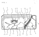
- Fig. 1 is a plan view of an outdoor unit of an air conditioner according to an explanatory Embodiment 1 when viewed from a top
- Fig. 2 is an explanatory drawing showing a partition plate and an electric component partition plate viewed in the direction indicated by an arrow X in Fig. 1
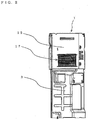
- Fig. 3 is a plan view showing a principal portion of the outdoor unit of the air conditioner with a particular emphasis on an electric component box
- Fig. 4 is a perspective view of the outdoor unit of the air conditioner viewed obliquely from the front
- Fig. 5 is a graph showing a relation between the position of a point of intersection c between an extension of the electric component partition plate and a line of projection of the electric component partition plate and a front edge of a vane in the outdoor unit of the air conditioner and the wind speed in a heat sink
- Fig. 6 is a schematic plan view showing a state of Arrangement 1 of a case where an angle of inclination ⁇ of the electric component partition plate in the outdoor unit of the air conditioner is narrow
- Fig. 7 is a schematic plan view showing a state of Arrangement 2 of a case where the angle of inclination ⁇ of the electric component partition plate in the outdoor unit of the air conditioner is wide.
- an outdoor unit 1 of the air conditioner has a configuration in which the interior of the outdoor unit is divided into a machinery chamber M and a heat exchanger chamber H by a partition plate 3 formed of a sheet metal extending upright from a bottom plate 2 to halfway to a top thereof and an electric component box 14 placed on the partition plate 3.
- the machinery chamber M includes a compressor 4 and the like for compressing a refrigerant to a high-temperature high-pressure state.
- a heat exchanger 5 for performing heat exchange between the refrigerant compressed to high-temperature and high-pressure by the compressor 4 and the outdoor air, a propeller fan 6 for blowing air to the heat exchanger 5 for promoting the heat exchange in the heat exchanger 5, and a fan motor 7 for rotating the propeller fan 6 are provided in the heat exchanger chamber H when the air conditioner is in a cooling operation.
- a front plate 8 which constitutes the outdoor unit 1 is provided with a horn-shaped bell mouth 10 so as to project toward the propeller fan.
- the bell mouth 10 is configured to rectify air blown out from a blowout port 9 being opened in the front plate 8, and is arranged outside the propeller fan 6 so as to keep a constant distance from the propeller fan 6.
- the propeller fan 6 has a structure having a plurality of curved vanes formed integrally around a hub 11, and a portion of the vane on the side of a front surface of the outdoor unit is referred to as a front edge of a vane 12.
- the propeller fan 6 is fixed at a center of the hub 11 to a shaft of the fan motor 7. The rotation of the propeller fan 6 in association with driving of the fan motor 7 generates a flow of air in the interior of the heat exchanger chamber H in the outdoor unit 1.
- an electronic substrate 13 and the like having a power module mounted thereon is provided in the interior of the electric component box 14 mounted on the partition plate 3 .
- an electric component partition plate 15 which forms a surface of the electric component box 14 and divides the interior of the electric component box 14 and the heat exchanger chamber H is in contact with an end of the heat exchanger 5 on the side of a back surface of the heat exchanger chamber H, and the other end thereof is in contact with the front plate 8, so that the electric component box 14 is secured to the heat exchanger 5 and the front plate 8 by screws or the like.
- the electric component partition plate 15 is arranged so that a surface on the side of a back surface of the outdoor unit forms an angle of inclination ⁇ with respect to the heat exchanger 5.
- the angle of inclination ⁇ of the electric component partition plate 15 is an angle falling within a range which allows an extended line A, being an extended line of the electric component partition plate 15 toward the front surface of the outdoor unit, to intersect the line of projection B of the front edge of a vane 12 of the propeller fan 6 on the side of the electric component box projecting from the top of the outdoor unit.
- the angle of inclination ⁇ is an angle which allows the point of intersection c between the extended line A of the electric component partition plate 15 extending toward the front surface of the outdoor unit and the line of projection B of the front edge of a vane 12 to fall within a range from an end point d of the hub 11 to an outer diameter point e of the front edge of a vane 12 of the propeller fan 6 on the side of the electric component box.
- the electric component partition plate 15 is bent into an elbow shape at a midpoint toward inside the electric component box so as to avoid interference with the propeller fan 6 and the bell mouth 10, and is fixed at the end thereof to the front plate 8.
- the electric component partition plate 15 is provided with an opening, and the electronic substrate 13 having the power module or the like for driving and controlling the compressor 4 and the fan motor 7 is fitted and fixed to the opening so as to be positioned inside the electric component box.
- a heat sink 17 for cooling the power module which includes a plurality of heat radiation fins 16 provided upright on one surface thereof, is attached to the opening of the electric component partition plate 15 in parallel to a front surface of the electric component partition plate 15 with screws or the like so as to be in contact with the back side of the electronic substrate 13.
- the plurality of heat radiation fins 16 of the heat sink 17 project toward the heat exchanger chamber side of the electric component partition plate 15, and are arranged with intervals in the vertical direction toward the bottom plate 2 when viewed from the ceiling of the outdoor unit.
- the heat sink 17 and the plurality of heat radiation fins 16 are arranged so as to extend in parallel to a flow of the air on the electric component partition plate 15.
- the heat sink 17 for cooling the power module which includes the plurality of heat radiation fins 16 on one surface thereof, is molded by an extrusion method or the like using a metal having a high thermal conductivity such as aluminum as a material in order to prevent the temperature of the power module from exceeding a heat resistant temperature and causing damages and breakdown.
- Air taken by the rotation of the propeller fan 6 from the back surface of the outdoor unit is subjected to the heat exchange with respect to the refrigerant in the heat exchanger 5, passes through the spaces among the plurality of vanes of the propeller fan 6 or a space between the propeller fan 6 and the bell mouth 10, and is blown out from the blowout port 9 of the front plate 8 of the outdoor unit.
- part of the air taken through the heat exchanger 5 flows from an inlet port of the heat sink 17 smoothly along the electric component partition plate 15 without meandering significantly, passes through the plurality of heat radiation fins 16 arranged in parallel to the flow of air on the electric component partition plate 15 without allowing the air escaping from a midsection of the heat sink 17, and is blown out from an outlet port of the heat sink 17, so that the heat sink 17 is cooled, and the power module on the electronic substrate 13, which is in contact with the heat sink 17, is also cooled.
- the electric component partition plate 15 is provided in such a manner that the point of intersection c between the extended line A of the electric component partition plate 15 extending toward the front surface of the outdoor unit and the line of projection B of the front edge of a vane 12 of the propeller fan 6 on the side of the electric component box falls within the range from the end point d of the hub 11 on the line of projection to the outer diameter point e of the front edge of a vane 12 of the propeller fan 6 on the side of the electric component box, the plurality of heat radiation fins 16 of the heat sink 17 are arranged at intervals in the vertical direction toward the bottom plate 2 when viewed from the top of the outdoor unit, and the plurality of heat radiation fins 16 are arranged in parallel to the flow of the air on the electric component partition plate 15. Therefore, advantages described from (1) to (5) are achieved.
- Fig. 5 is the graph showing flow velocities at the inlet port and the outlet port of the heat sink 17 and average flow velocities of the inlet port and the outlet port with respect to the position of the point of intersection c between the extended line A of the electric component partition plate 15 and the line of projection B of the front edge of a vane 12, in which the lateral axis shows from the axial center of the propeller fan 6 as an original point 0 to an end point of the blowout port 9 on the side of the electric component box as 0.6.
- Fig. 8 is a plan view of an outdoor unit of an air conditioner according to inventive Embodiment 2 when viewed from the top
- Fig. 9 is a cross-sectional view showing an electric component box and a heat sink in the outdoor unit of the air conditioner
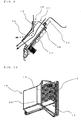
- Fig. 10 is a perspective view showing the heat sink and a wind direction guide in the outdoor unit of the air conditioner.
- the electric component partition plate 15 is provided at the angle of inclination ⁇ which allows the point of intersection c between the extended line A of the electric component partition plate 15 extending toward the front surface of the outdoor unit and the line of projection B extending toward the propeller fan 6 on the side of the electric component box to fall within the range between the end point d of the hub 11 on the line of projection B and the outer diameter point e of the front edge of a vane 12, the plurality of heat radiation fins 16 of the heat sink 17 are arranged at the intervals in the vertical direction toward the bottom plate 2 when viewed from the top of the outdoor unit, and the plurality of heat radiation fins 16 are arranged in parallel to the flow of the air on the electric component partition plate 15.
- the cooling efficiency of the heat sink 17 is further improved by adding a certain configuration to the configuration in Embodiment 1.
- a wind direction guide 18 molded using a material such as resin is srcewed and fixed to the heat sink 17 of the outdoor unit 1 of the air conditioner configured in the same manner as in Embodiment 1 with screws or the like so as to cover the plurality of heat radiation fins 16.
- a horn-shaped inlet member 19 having a port widening toward the heat exchanger and a lid portion 20 covering a section of the inlet member 19 from an end on the side of the heat sink 17 to the outlet port of the heat sink 17 while keeping a constant space with respect to the heat radiation fins 16 are integrally formed.
- the inlet member 19 is attached at a certain angle ⁇ of inclination with respect to one side portion of the heat radiation fins 16 in the longitudinal direction when viewed from the top of the outdoor unit, and the surface area of the opening of the inlet member 19 on the side of the heat exchanger is larger than the surface area of the opening of the heat sink 17 on the side of the inlet port.
- a configuration in Embodiment 2 has advantages such that the flow rate of the air flowing into the heat sink 17 is increased, the flow speed of the air passing through the heat radiation fins 16 can be increased, and the cooling efficiency of the heat sink 17 can be enhanced.
- the air flowing inward from the inlet port of the heat sink 17 is prevented from leaving and escaping from the heat radiation fins 16 at some midpoint of the heat sink 17 as shown by an arrow of a solid line in Fig. 9 , and reaches the outlet port of the heat sink 17.
- the cooling efficiency of the heat sink 17 is enhanced. Granted that the lid portion 20 is not provided, with the provision of the inlet member 19 on the side of the inlet port of the heat sink 17, the air is curved at some midpoint of the heat sink 17, leaves the heat radiation fins 16 as indicated by an arrow of a broken line in Fig. 9 , and cannot reach the outlet port of the heat sink 17. Therefore, the cooling efficiency of the heat sink 17 is lowered in comparison with the case where the lid portion 20 is provided.
- the wind direction guide 18 may be molded using synthetic resin or the like, the shape can be changed freely to some extent. Therefore, when further enhancement of the cooling efficiency of the heat sink 17 is wanted, the angle ⁇ of attachment of the inlet member 19 of the wind direction guide 18 may be increased so that the surface area of the opening is increased in order to increase the volume of the air flowing into the inlet port of the heat sink 17.
Landscapes
- Engineering & Computer Science (AREA)
- Chemical & Material Sciences (AREA)
- Combustion & Propulsion (AREA)
- Mechanical Engineering (AREA)
- General Engineering & Computer Science (AREA)
- Other Air-Conditioning Systems (AREA)
- Cooling Or The Like Of Electrical Apparatus (AREA)
Applications Claiming Priority (1)
| Application Number | Priority Date | Filing Date | Title |
|---|---|---|---|
| JP2009084746A JP2010236781A (ja) | 2009-03-31 | 2009-03-31 | 空気調和機の室外機 |
Publications (3)
| Publication Number | Publication Date |
|---|---|
| EP2241830A2 EP2241830A2 (en) | 2010-10-20 |
| EP2241830A3 EP2241830A3 (en) | 2014-04-30 |
| EP2241830B1 true EP2241830B1 (en) | 2017-10-25 |
Family
ID=42289321
Family Applications (1)
| Application Number | Title | Priority Date | Filing Date |
|---|---|---|---|
| EP10001910.8A Not-in-force EP2241830B1 (en) | 2009-03-31 | 2010-02-22 | Outdoor unit of air conditioner |
Country Status (3)
| Country | Link |
|---|---|
| EP (1) | EP2241830B1 (enExample) |
| JP (1) | JP2010236781A (enExample) |
| AU (1) | AU2010200570B2 (enExample) |
Families Citing this family (24)
| Publication number | Priority date | Publication date | Assignee | Title |
|---|---|---|---|---|
| JP5858777B2 (ja) * | 2011-12-28 | 2016-02-10 | 三菱電機株式会社 | 空気調和装置 |
| JP5851303B2 (ja) * | 2012-03-28 | 2016-02-03 | 三菱電機株式会社 | 冷凍サイクル装置および室外熱源ユニット |
| CN103673136B (zh) * | 2012-09-18 | 2016-04-27 | 珠海格力电器股份有限公司 | 空调器室外机的隔板及具有该隔板的空调器 |
| KR102170317B1 (ko) * | 2014-01-14 | 2020-10-26 | 엘지전자 주식회사 | 공기조화기의 실외기 |
| CN104913399B (zh) * | 2014-03-10 | 2019-07-05 | 珠海格力电器股份有限公司 | 室外机 |
| JP6011669B1 (ja) * | 2015-03-31 | 2016-10-19 | ダイキン工業株式会社 | 室外機 |
| CN105042724A (zh) * | 2015-08-31 | 2015-11-11 | 珠海格力电器股份有限公司 | 空调室外机 |
| CN107328074B (zh) * | 2016-04-29 | 2023-10-31 | 广东美的制冷设备有限公司 | 空调外壳、窗机空调及其制冷运行方法 |
| CN106196336B (zh) * | 2016-07-14 | 2019-08-06 | 海信科龙电器股份有限公司 | 应用于变频空调的散热系统、变频空调室外机和变频空调 |
| CN107465366B (zh) * | 2017-03-24 | 2024-02-13 | 万洲电气股份有限公司 | 一种手车式中高压固态软起动器 |
| CN106839164B (zh) * | 2017-03-27 | 2022-11-08 | 广东美的制冷设备有限公司 | 室外机及空调器 |
| CN107192043A (zh) * | 2017-06-21 | 2017-09-22 | 青岛海信日立空调系统有限公司 | 变频空调室外机及其变频模块冷却方法和装置、变频空调 |
| US11879648B2 (en) | 2018-02-05 | 2024-01-23 | Mitsubishi Electric Corporation | Outdoor machine and air conditioner |
| US11956926B2 (en) | 2018-03-12 | 2024-04-09 | Mitsubishi Electric Corporation | Outdoor unit |
| CN112513534B (zh) * | 2018-08-09 | 2022-06-21 | 三菱电机株式会社 | 室外机及空气调节机 |
| JPWO2020157871A1 (ja) * | 2019-01-30 | 2021-09-09 | 三菱電機株式会社 | 室外機および空気調和機 |
| CN111121176B (zh) * | 2020-01-19 | 2022-03-18 | 青岛海信日立空调系统有限公司 | 一种空调室外机及空调器 |
| CN119436295A (zh) * | 2020-03-17 | 2025-02-14 | 宁波奥克斯电气有限公司 | 一种底盘装配结构及空调器 |
| CN113915692B (zh) * | 2020-07-07 | 2025-05-06 | 宁波奥克斯电气有限公司 | 一种电控盒组件、空调器及外机主板温度控制方法 |
| CN111698862B (zh) * | 2020-07-08 | 2023-10-13 | 青岛海信网络能源股份有限公司 | 氟泵空调单元柜及空调系统 |
| CN116887567A (zh) | 2020-08-26 | 2023-10-13 | 广东美的暖通设备有限公司 | 电控盒及空调系统 |
| WO2022042556A1 (zh) * | 2020-08-26 | 2022-03-03 | 广东美的暖通设备有限公司 | 空调装置以及电控盒 |
| CN115406009B (zh) * | 2021-05-28 | 2025-04-22 | 宁波奥克斯电气有限公司 | 一种空调器 |
| KR20260039413A (ko) * | 2024-09-13 | 2026-03-20 | 삼성전자주식회사 | 공기조화기의 실외기 |
Family Cites Families (14)
| Publication number | Priority date | Publication date | Assignee | Title |
|---|---|---|---|---|
| JPS5627568U (enExample) * | 1979-08-09 | 1981-03-14 | ||
| JPS63140232A (ja) * | 1986-12-03 | 1988-06-11 | Hitachi Ltd | 空気調和機 |
| JPH03100728U (enExample) * | 1990-01-31 | 1991-10-21 | ||
| JP3039360B2 (ja) * | 1996-02-29 | 2000-05-08 | ダイキン工業株式会社 | 空気調和機用室外機 |
| JP3047810B2 (ja) * | 1996-04-19 | 2000-06-05 | ダイキン工業株式会社 | 電装品集約ボード構造 |
| JPH1026372A (ja) * | 1996-07-10 | 1998-01-27 | Fujitsu General Ltd | 空気調和機の室外機 |
| JPH1163573A (ja) * | 1997-08-20 | 1999-03-05 | Fujitsu General Ltd | 空気調和機の室外機 |
| JP2000277955A (ja) * | 1999-03-29 | 2000-10-06 | Kokusai Electric Co Ltd | 電子機器の冷却構造 |
| JP3698152B2 (ja) * | 2003-10-08 | 2005-09-21 | ダイキン工業株式会社 | 空気調和装置の室外ユニット |
| JPWO2006054547A1 (ja) * | 2004-11-16 | 2008-05-29 | ダイキン工業株式会社 | 空気調和機の室外機 |
| JP3985833B2 (ja) * | 2005-11-07 | 2007-10-03 | ダイキン工業株式会社 | 電装品アセンブリ及びそれを備えた空気調和装置の室外ユニット |
| JP3985834B2 (ja) * | 2005-11-07 | 2007-10-03 | ダイキン工業株式会社 | 電装品アセンブリ、それを備えた空気調和装置の室外ユニット、及び空気調和装置 |
| JP3985835B2 (ja) * | 2005-11-07 | 2007-10-03 | ダイキン工業株式会社 | 電装品アセンブリ及びそれを備えた空気調和装置の室外ユニット |
| JP4859776B2 (ja) * | 2007-07-27 | 2012-01-25 | 三洋電機株式会社 | 室外ユニット |
-
2009
- 2009-03-31 JP JP2009084746A patent/JP2010236781A/ja active Pending
-
2010
- 2010-02-16 AU AU2010200570A patent/AU2010200570B2/en not_active Ceased
- 2010-02-22 EP EP10001910.8A patent/EP2241830B1/en not_active Not-in-force
Non-Patent Citations (1)
| Title |
|---|
| None * |
Also Published As
| Publication number | Publication date |
|---|---|
| EP2241830A2 (en) | 2010-10-20 |
| AU2010200570B2 (en) | 2010-12-23 |
| AU2010200570A1 (en) | 2010-10-14 |
| JP2010236781A (ja) | 2010-10-21 |
| EP2241830A3 (en) | 2014-04-30 |
Similar Documents
| Publication | Publication Date | Title |
|---|---|---|
| EP2241830B1 (en) | Outdoor unit of air conditioner | |
| EP2781844B1 (en) | Turbo fan and ceiling type air conditioner using the same | |
| US6338676B1 (en) | Air conditioner | |
| EP2918936B1 (en) | Air conditioner | |
| US8172524B2 (en) | Fan including specific stationary vane arrangement | |
| JP6818558B2 (ja) | 空気調和機の室外機 | |
| JP6578907B2 (ja) | 天井埋込型空気調和機 | |
| US9335059B2 (en) | Ceiling type air conditioner | |
| EP3321597B1 (en) | Indoor unit for air conditioner | |
| JP2004156885A (ja) | 空調用室内ユニットおよび天井埋込型空気調和機 | |
| JP2017223173A (ja) | 送風機および冷凍サイクル装置の室外機 | |
| US11391473B2 (en) | Outdoor unit and air conditioner | |
| JP4986696B2 (ja) | 冷凍空調装置 | |
| CN110506164A (zh) | 螺旋桨式风扇及空调装置用室外机 | |
| JP2014005975A (ja) | 空気調和機の室外機 | |
| JPWO2017042865A1 (ja) | 空気調和機の室外機 | |
| KR101784881B1 (ko) | 팬 슈라우드 조립체 | |
| JP4937331B2 (ja) | 送風機及びヒートポンプ装置 | |
| JP6758992B2 (ja) | 室内機および空気調和機 | |
| JP7170755B2 (ja) | 空気調和装置の室内機及び空気調和装置 | |
| US20160252259A1 (en) | Indoor Unit of Air Conditioner and Air Conditioner Including the Same | |
| US11879648B2 (en) | Outdoor machine and air conditioner | |
| CN215863768U (zh) | 出风网罩及空调器 | |
| KR100760128B1 (ko) | 천장형 공기조화기 | |
| US11788738B2 (en) | Outdoor unit and air conditioner |
Legal Events
| Date | Code | Title | Description |
|---|---|---|---|
| PUAI | Public reference made under article 153(3) epc to a published international application that has entered the european phase |
Free format text: ORIGINAL CODE: 0009012 |
|
| AK | Designated contracting states |
Kind code of ref document: A2 Designated state(s): AT BE BG CH CY CZ DE DK EE ES FI FR GB GR HR HU IE IS IT LI LT LU LV MC MK MT NL NO PL PT RO SE SI SK SM TR |
|
| AX | Request for extension of the european patent |
Extension state: AL BA RS |
|
| PUAL | Search report despatched |
Free format text: ORIGINAL CODE: 0009013 |
|
| AK | Designated contracting states |
Kind code of ref document: A3 Designated state(s): AT BE BG CH CY CZ DE DK EE ES FI FR GB GR HR HU IE IS IT LI LT LU LV MC MK MT NL NO PL PT RO SE SI SK SM TR |
|
| AX | Request for extension of the european patent |
Extension state: AL BA RS |
|
| RIC1 | Information provided on ipc code assigned before grant |
Ipc: F24F 1/00 20110101AFI20140327BHEP |
|
| 17P | Request for examination filed |
Effective date: 20141030 |
|
| RBV | Designated contracting states (corrected) |
Designated state(s): AT BE BG CH CY CZ DE DK EE ES FI FR GB GR HR HU IE IS IT LI LT LU LV MC MK MT NL NO PL PT RO SE SI SK SM TR |
|
| 17Q | First examination report despatched |
Effective date: 20160225 |
|
| GRAP | Despatch of communication of intention to grant a patent |
Free format text: ORIGINAL CODE: EPIDOSNIGR1 |
|
| GRAJ | Information related to disapproval of communication of intention to grant by the applicant or resumption of examination proceedings by the epo deleted |
Free format text: ORIGINAL CODE: EPIDOSDIGR1 |
|
| INTG | Intention to grant announced |
Effective date: 20170307 |
|
| INTC | Intention to grant announced (deleted) | ||
| GRAP | Despatch of communication of intention to grant a patent |
Free format text: ORIGINAL CODE: EPIDOSNIGR1 |
|
| INTG | Intention to grant announced |
Effective date: 20170515 |
|
| GRAS | Grant fee paid |
Free format text: ORIGINAL CODE: EPIDOSNIGR3 |
|
| GRAA | (expected) grant |
Free format text: ORIGINAL CODE: 0009210 |
|
| AK | Designated contracting states |
Kind code of ref document: B1 Designated state(s): AT BE BG CH CY CZ DE DK EE ES FI FR GB GR HR HU IE IS IT LI LT LU LV MC MK MT NL NO PL PT RO SE SI SK SM TR |
|
| REG | Reference to a national code |
Ref country code: GB Ref legal event code: FG4D |
|
| REG | Reference to a national code |
Ref country code: CH Ref legal event code: EP |
|
| REG | Reference to a national code |
Ref country code: AT Ref legal event code: REF Ref document number: 940295 Country of ref document: AT Kind code of ref document: T Effective date: 20171115 |
|
| REG | Reference to a national code |
Ref country code: IE Ref legal event code: FG4D |
|
| REG | Reference to a national code |
Ref country code: DE Ref legal event code: R096 Ref document number: 602010046134 Country of ref document: DE |
|
| REG | Reference to a national code |
Ref country code: NL Ref legal event code: MP Effective date: 20171025 |
|
| REG | Reference to a national code |
Ref country code: LT Ref legal event code: MG4D |
|
| REG | Reference to a national code |
Ref country code: AT Ref legal event code: MK05 Ref document number: 940295 Country of ref document: AT Kind code of ref document: T Effective date: 20171025 |
|
| PG25 | Lapsed in a contracting state [announced via postgrant information from national office to epo] |
Ref country code: NL Free format text: LAPSE BECAUSE OF FAILURE TO SUBMIT A TRANSLATION OF THE DESCRIPTION OR TO PAY THE FEE WITHIN THE PRESCRIBED TIME-LIMIT Effective date: 20171025 |
|
| PG25 | Lapsed in a contracting state [announced via postgrant information from national office to epo] |
Ref country code: ES Free format text: LAPSE BECAUSE OF FAILURE TO SUBMIT A TRANSLATION OF THE DESCRIPTION OR TO PAY THE FEE WITHIN THE PRESCRIBED TIME-LIMIT Effective date: 20171025 Ref country code: SE Free format text: LAPSE BECAUSE OF FAILURE TO SUBMIT A TRANSLATION OF THE DESCRIPTION OR TO PAY THE FEE WITHIN THE PRESCRIBED TIME-LIMIT Effective date: 20171025 Ref country code: LT Free format text: LAPSE BECAUSE OF FAILURE TO SUBMIT A TRANSLATION OF THE DESCRIPTION OR TO PAY THE FEE WITHIN THE PRESCRIBED TIME-LIMIT Effective date: 20171025 Ref country code: FI Free format text: LAPSE BECAUSE OF FAILURE TO SUBMIT A TRANSLATION OF THE DESCRIPTION OR TO PAY THE FEE WITHIN THE PRESCRIBED TIME-LIMIT Effective date: 20171025 Ref country code: NO Free format text: LAPSE BECAUSE OF FAILURE TO SUBMIT A TRANSLATION OF THE DESCRIPTION OR TO PAY THE FEE WITHIN THE PRESCRIBED TIME-LIMIT Effective date: 20180125 |
|
| PG25 | Lapsed in a contracting state [announced via postgrant information from national office to epo] |
Ref country code: HR Free format text: LAPSE BECAUSE OF FAILURE TO SUBMIT A TRANSLATION OF THE DESCRIPTION OR TO PAY THE FEE WITHIN THE PRESCRIBED TIME-LIMIT Effective date: 20171025 Ref country code: AT Free format text: LAPSE BECAUSE OF FAILURE TO SUBMIT A TRANSLATION OF THE DESCRIPTION OR TO PAY THE FEE WITHIN THE PRESCRIBED TIME-LIMIT Effective date: 20171025 Ref country code: GR Free format text: LAPSE BECAUSE OF FAILURE TO SUBMIT A TRANSLATION OF THE DESCRIPTION OR TO PAY THE FEE WITHIN THE PRESCRIBED TIME-LIMIT Effective date: 20180126 Ref country code: BG Free format text: LAPSE BECAUSE OF FAILURE TO SUBMIT A TRANSLATION OF THE DESCRIPTION OR TO PAY THE FEE WITHIN THE PRESCRIBED TIME-LIMIT Effective date: 20180125 Ref country code: PT Free format text: LAPSE BECAUSE OF FAILURE TO SUBMIT A TRANSLATION OF THE DESCRIPTION OR TO PAY THE FEE WITHIN THE PRESCRIBED TIME-LIMIT Effective date: 20180226 Ref country code: IS Free format text: LAPSE BECAUSE OF FAILURE TO SUBMIT A TRANSLATION OF THE DESCRIPTION OR TO PAY THE FEE WITHIN THE PRESCRIBED TIME-LIMIT Effective date: 20180225 Ref country code: LV Free format text: LAPSE BECAUSE OF FAILURE TO SUBMIT A TRANSLATION OF THE DESCRIPTION OR TO PAY THE FEE WITHIN THE PRESCRIBED TIME-LIMIT Effective date: 20171025 |
|
| REG | Reference to a national code |
Ref country code: DE Ref legal event code: R097 Ref document number: 602010046134 Country of ref document: DE |
|
| PG25 | Lapsed in a contracting state [announced via postgrant information from national office to epo] |
Ref country code: CZ Free format text: LAPSE BECAUSE OF FAILURE TO SUBMIT A TRANSLATION OF THE DESCRIPTION OR TO PAY THE FEE WITHIN THE PRESCRIBED TIME-LIMIT Effective date: 20171025 Ref country code: CY Free format text: LAPSE BECAUSE OF FAILURE TO SUBMIT A TRANSLATION OF THE DESCRIPTION OR TO PAY THE FEE WITHIN THE PRESCRIBED TIME-LIMIT Effective date: 20171025 Ref country code: EE Free format text: LAPSE BECAUSE OF FAILURE TO SUBMIT A TRANSLATION OF THE DESCRIPTION OR TO PAY THE FEE WITHIN THE PRESCRIBED TIME-LIMIT Effective date: 20171025 Ref country code: DK Free format text: LAPSE BECAUSE OF FAILURE TO SUBMIT A TRANSLATION OF THE DESCRIPTION OR TO PAY THE FEE WITHIN THE PRESCRIBED TIME-LIMIT Effective date: 20171025 Ref country code: SK Free format text: LAPSE BECAUSE OF FAILURE TO SUBMIT A TRANSLATION OF THE DESCRIPTION OR TO PAY THE FEE WITHIN THE PRESCRIBED TIME-LIMIT Effective date: 20171025 |
|
| PG25 | Lapsed in a contracting state [announced via postgrant information from national office to epo] |
Ref country code: RO Free format text: LAPSE BECAUSE OF FAILURE TO SUBMIT A TRANSLATION OF THE DESCRIPTION OR TO PAY THE FEE WITHIN THE PRESCRIBED TIME-LIMIT Effective date: 20171025 Ref country code: SM Free format text: LAPSE BECAUSE OF FAILURE TO SUBMIT A TRANSLATION OF THE DESCRIPTION OR TO PAY THE FEE WITHIN THE PRESCRIBED TIME-LIMIT Effective date: 20171025 Ref country code: PL Free format text: LAPSE BECAUSE OF FAILURE TO SUBMIT A TRANSLATION OF THE DESCRIPTION OR TO PAY THE FEE WITHIN THE PRESCRIBED TIME-LIMIT Effective date: 20171025 |
|
| PLBE | No opposition filed within time limit |
Free format text: ORIGINAL CODE: 0009261 |
|
| STAA | Information on the status of an ep patent application or granted ep patent |
Free format text: STATUS: NO OPPOSITION FILED WITHIN TIME LIMIT |
|
| REG | Reference to a national code |
Ref country code: CH Ref legal event code: PL |
|
| PG25 | Lapsed in a contracting state [announced via postgrant information from national office to epo] |
Ref country code: MC Free format text: LAPSE BECAUSE OF FAILURE TO SUBMIT A TRANSLATION OF THE DESCRIPTION OR TO PAY THE FEE WITHIN THE PRESCRIBED TIME-LIMIT Effective date: 20171025 |
|
| 26N | No opposition filed |
Effective date: 20180726 |
|
| GBPC | Gb: european patent ceased through non-payment of renewal fee |
Effective date: 20180222 |
|
| REG | Reference to a national code |
Ref country code: IE Ref legal event code: MM4A |
|
| REG | Reference to a national code |
Ref country code: BE Ref legal event code: MM Effective date: 20180228 |
|
| PG25 | Lapsed in a contracting state [announced via postgrant information from national office to epo] |
Ref country code: LU Free format text: LAPSE BECAUSE OF NON-PAYMENT OF DUE FEES Effective date: 20180222 Ref country code: SI Free format text: LAPSE BECAUSE OF FAILURE TO SUBMIT A TRANSLATION OF THE DESCRIPTION OR TO PAY THE FEE WITHIN THE PRESCRIBED TIME-LIMIT Effective date: 20171025 Ref country code: LI Free format text: LAPSE BECAUSE OF NON-PAYMENT OF DUE FEES Effective date: 20180228 Ref country code: CH Free format text: LAPSE BECAUSE OF NON-PAYMENT OF DUE FEES Effective date: 20180228 |
|
| REG | Reference to a national code |
Ref country code: FR Ref legal event code: ST Effective date: 20181031 |
|
| PG25 | Lapsed in a contracting state [announced via postgrant information from national office to epo] |
Ref country code: IE Free format text: LAPSE BECAUSE OF NON-PAYMENT OF DUE FEES Effective date: 20180222 |
|
| PG25 | Lapsed in a contracting state [announced via postgrant information from national office to epo] |
Ref country code: BE Free format text: LAPSE BECAUSE OF NON-PAYMENT OF DUE FEES Effective date: 20180228 Ref country code: FR Free format text: LAPSE BECAUSE OF NON-PAYMENT OF DUE FEES Effective date: 20180228 Ref country code: GB Free format text: LAPSE BECAUSE OF NON-PAYMENT OF DUE FEES Effective date: 20180222 |
|
| PG25 | Lapsed in a contracting state [announced via postgrant information from national office to epo] |
Ref country code: MT Free format text: LAPSE BECAUSE OF NON-PAYMENT OF DUE FEES Effective date: 20180222 |
|
| PG25 | Lapsed in a contracting state [announced via postgrant information from national office to epo] |
Ref country code: TR Free format text: LAPSE BECAUSE OF FAILURE TO SUBMIT A TRANSLATION OF THE DESCRIPTION OR TO PAY THE FEE WITHIN THE PRESCRIBED TIME-LIMIT Effective date: 20171025 |
|
| PG25 | Lapsed in a contracting state [announced via postgrant information from national office to epo] |
Ref country code: HU Free format text: LAPSE BECAUSE OF FAILURE TO SUBMIT A TRANSLATION OF THE DESCRIPTION OR TO PAY THE FEE WITHIN THE PRESCRIBED TIME-LIMIT; INVALID AB INITIO Effective date: 20100222 |
|
| PG25 | Lapsed in a contracting state [announced via postgrant information from national office to epo] |
Ref country code: MK Free format text: LAPSE BECAUSE OF NON-PAYMENT OF DUE FEES Effective date: 20171025 |
|
| REG | Reference to a national code |
Ref country code: DE Ref legal event code: R084 Ref document number: 602010046134 Country of ref document: DE |
|
| P01 | Opt-out of the competence of the unified patent court (upc) registered |
Effective date: 20230512 |
|
| PGFP | Annual fee paid to national office [announced via postgrant information from national office to epo] |
Ref country code: DE Payment date: 20231228 Year of fee payment: 15 |
|
| PGFP | Annual fee paid to national office [announced via postgrant information from national office to epo] |
Ref country code: IT Payment date: 20240111 Year of fee payment: 15 |
|
| REG | Reference to a national code |
Ref country code: DE Ref legal event code: R119 Ref document number: 602010046134 Country of ref document: DE |
|
| PG25 | Lapsed in a contracting state [announced via postgrant information from national office to epo] |
Ref country code: DE Free format text: LAPSE BECAUSE OF NON-PAYMENT OF DUE FEES Effective date: 20250902 |
|
| PG25 | Lapsed in a contracting state [announced via postgrant information from national office to epo] |
Ref country code: IT Free format text: LAPSE BECAUSE OF NON-PAYMENT OF DUE FEES Effective date: 20250222 |