EP2240340B1 - Unité de production de puissance hydraulique et système d'entraînement hybride hydraulique comprenant celle-ci - Google Patents
Unité de production de puissance hydraulique et système d'entraînement hybride hydraulique comprenant celle-ci Download PDFInfo
- Publication number
- EP2240340B1 EP2240340B1 EP09701463.3A EP09701463A EP2240340B1 EP 2240340 B1 EP2240340 B1 EP 2240340B1 EP 09701463 A EP09701463 A EP 09701463A EP 2240340 B1 EP2240340 B1 EP 2240340B1
- Authority
- EP
- European Patent Office
- Prior art keywords
- hydraulic
- power output
- input shaft
- drive
- output unit
- Prior art date
- Legal status (The legal status is an assumption and is not a legal conclusion. Google has not performed a legal analysis and makes no representation as to the accuracy of the status listed.)
- Not-in-force
Links
Images

Classifications
-
- F—MECHANICAL ENGINEERING; LIGHTING; HEATING; WEAPONS; BLASTING
- F16—ENGINEERING ELEMENTS AND UNITS; GENERAL MEASURES FOR PRODUCING AND MAINTAINING EFFECTIVE FUNCTIONING OF MACHINES OR INSTALLATIONS; THERMAL INSULATION IN GENERAL
- F16H—GEARING
- F16H47/00—Combinations of mechanical gearing with fluid clutches or fluid gearing
- F16H47/02—Combinations of mechanical gearing with fluid clutches or fluid gearing the fluid gearing being of the volumetric type
-
- B—PERFORMING OPERATIONS; TRANSPORTING
- B60—VEHICLES IN GENERAL
- B60K—ARRANGEMENT OR MOUNTING OF PROPULSION UNITS OR OF TRANSMISSIONS IN VEHICLES; ARRANGEMENT OR MOUNTING OF PLURAL DIVERSE PRIME-MOVERS IN VEHICLES; AUXILIARY DRIVES FOR VEHICLES; INSTRUMENTATION OR DASHBOARDS FOR VEHICLES; ARRANGEMENTS IN CONNECTION WITH COOLING, AIR INTAKE, GAS EXHAUST OR FUEL SUPPLY OF PROPULSION UNITS IN VEHICLES
- B60K6/00—Arrangement or mounting of plural diverse prime-movers for mutual or common propulsion, e.g. hybrid propulsion systems comprising electric motors and internal combustion engines ; Control systems therefor, i.e. systems controlling two or more prime movers, or controlling one of these prime movers and any of the transmission, drive or drive units Informative references: mechanical gearings with secondary electric drive F16H3/72; arrangements for handling mechanical energy structurally associated with the dynamo-electric machine H02K7/00; machines comprising structurally interrelated motor and generator parts H02K51/00; dynamo-electric machines not otherwise provided for in H02K see H02K99/00
- B60K6/08—Prime-movers comprising combustion engines and mechanical or fluid energy storing means
- B60K6/12—Prime-movers comprising combustion engines and mechanical or fluid energy storing means by means of a chargeable fluidic accumulator
-
- Y—GENERAL TAGGING OF NEW TECHNOLOGICAL DEVELOPMENTS; GENERAL TAGGING OF CROSS-SECTIONAL TECHNOLOGIES SPANNING OVER SEVERAL SECTIONS OF THE IPC; TECHNICAL SUBJECTS COVERED BY FORMER USPC CROSS-REFERENCE ART COLLECTIONS [XRACs] AND DIGESTS
- Y02—TECHNOLOGIES OR APPLICATIONS FOR MITIGATION OR ADAPTATION AGAINST CLIMATE CHANGE
- Y02T—CLIMATE CHANGE MITIGATION TECHNOLOGIES RELATED TO TRANSPORTATION
- Y02T10/00—Road transport of goods or passengers
- Y02T10/60—Other road transportation technologies with climate change mitigation effect
- Y02T10/62—Hybrid vehicles
-
- Y—GENERAL TAGGING OF NEW TECHNOLOGICAL DEVELOPMENTS; GENERAL TAGGING OF CROSS-SECTIONAL TECHNOLOGIES SPANNING OVER SEVERAL SECTIONS OF THE IPC; TECHNICAL SUBJECTS COVERED BY FORMER USPC CROSS-REFERENCE ART COLLECTIONS [XRACs] AND DIGESTS
- Y10—TECHNICAL SUBJECTS COVERED BY FORMER USPC
- Y10T—TECHNICAL SUBJECTS COVERED BY FORMER US CLASSIFICATION
- Y10T74/00—Machine element or mechanism
- Y10T74/19—Gearing
- Y10T74/19149—Gearing with fluid drive
-
- Y—GENERAL TAGGING OF NEW TECHNOLOGICAL DEVELOPMENTS; GENERAL TAGGING OF CROSS-SECTIONAL TECHNOLOGIES SPANNING OVER SEVERAL SECTIONS OF THE IPC; TECHNICAL SUBJECTS COVERED BY FORMER USPC CROSS-REFERENCE ART COLLECTIONS [XRACs] AND DIGESTS
- Y10—TECHNICAL SUBJECTS COVERED BY FORMER USPC
- Y10T—TECHNICAL SUBJECTS COVERED BY FORMER US CLASSIFICATION
- Y10T74/00—Machine element or mechanism
- Y10T74/21—Elements
- Y10T74/2121—Flywheel, motion smoothing-type
- Y10T74/2131—Damping by absorbing vibration force [via rubber, elastomeric material, etc.]
Definitions
- This invention relates in general to a hydraulic power output unit for generating hydraulic power on a vehicle.
- this invention relates to an improved structure for such a hydraulic power output unit and to the use of such an improved hydraulic power output unit in a hydraulic hybrid drive system for propelling a vehicle.
- Drive train systems are widely used for generating power from a source and for transferring such power from the source to a driven mechanism.
- the source generates rotational power, and such rotational power is transferred from the source of rotational power to a rotatably driven mechanism.
- an engine generates rotational power, and such rotational power is transferred from an output shaft of the engine through a driveshaft to an input shaft of an axle assembly so as to rotatably drive the wheels of the vehicle.
- a hybrid drive system (also known as an energy recovery system) is provided in conjunction with the drive train system to decelerate the rotatably driven mechanism, accumulate the energy resulting from such deceleration, and use the accumulated energy to subsequently accelerate the rotatably driven mechanism.
- a typical hybrid drive system includes a reversible energy transfer machine that is coupled to the drive train system and an energy storage device that communicates with the reversible energy transfer machine.
- the hybrid drive system is operated in a retarding mode, wherein the reversible energy transfer machine slows the rotation of the rotatably driven mechanism and stores the kinetic energy of the vehicle in the energy storage device as potential energy.
- the hybrid drive system is operated in a driving mode, wherein the potential energy stored in the energy storage device is supplied to the reversible energy transfer machine to rotatably drive the rotatably driven mechanism.
- pressurized fluid is used as the actuating mechanism.
- an accumulator functions as the energy storage device, and one or more hydraulic pump/motors function as reversible hydraulic machines.
- hydraulic power output units for providing hydraulic power to operate certain vehicle functions or accessories.
- a hydraulic accessory that is driven by a hydraulic power output unit is a trash compacting cylinder on a refuse truck.
- the hydraulic power output unit is often embodied as a hydraulic pump that is selectively connectable to the vehicle transmission through a conventional power take-off.
- a hydraulic power output unit When the vehicle is equipped with a hydraulic hybrid drive train system, a hydraulic power output unit provides hydraulic power to drive the driven wheels of the vehicle.
- hydraulic hybrid drive train systems There are generally two types of hydraulic hybrid drive train systems.
- a parallel hybrid hydraulic drive train system the vehicle includes both a conventional transmission as well as a hydraulic drive train system.
- a series hybrid hydraulic drive train system includes only the hydraulic drive train system, and the conventional transmission is removed from the vehicle.
- the hydraulic power output unit forms a portion of the hydraulic drive train system for providing hydraulic power to a hydraulic motor for driving the driven wheels of the vehicle.
- US 2002/0125058 discloses a drive assembly according to the preamble of claim 1 for vehicles with front wheels and rear wheels, especially for tractors, agricultural machinery, construction machinery or for self-driving machines which have an engine, a first drive to drive the rear wheels, a second drive to drive the front wheels, an adjustable hydraulic pump driven by the engine, and an adjustable first hydraulic motor.
- the first hydraulic motor is connected to the first drive to drive the rear wheels.
- the first hydraulic motor may be connected to the second drive, to drive the front wheels.
- a second hydraulic motor can be connected to the second drive to drive the front wheels.
- the hydraulic power output unit includes a housing having an input shaft that extends within the housing and is adapted to be rotatably driven by a source of rotational power.
- a hydraulic pump is rotatably driven by the input driveshaft to pump hydraulic fluid.
- a vibration damper is provided within the housing for dampening vibrations in the input shaft.
- a hydraulic power output unit indicated generally at 10, in accordance with this invention.
- the hydraulic power output unit 10 of this invention will be described and illustrated in the context of a drive train system for a vehicle, specifically a hydraulic hybrid drive system. However, such description and illustration are intended merely to illustrate one environment in which this invention may be used. Thus, the scope of this invention is not intended to be limited for use with the specific hydraulic hybrid drive systems or vehicular drive train systems in general.
- the illustrated hydraulic power output unit 10 includes a housing 11 that is preferably formed from a durable and rigid material, such as a metallic material.
- the housing 11 of the hydraulic power output unit 10 may be formed from either a single piece of material or from a plurality of pieces of material that are connected together.
- the illustrated housing 11 has a first opening 12 formed through a first side thereof and a second opening 13 formed through a second side thereof that is opposite the first side. The purposes for these first and second openings 12 and 13 will be explained below.
- a conventional annular seal 12a is provided within the first opening 12 for a purpose that will also be explained below.
- the first side of the housing 11 may also be provided with a flange portion, such as shown at 14.
- the flange portion 14 may be provided to facilitate the mounting of the housing 11 on a support structure 15.
- the flange portion 14 may be used to facilitate the mounting of the housing 11 on a portion of a clutch housing 15 or other component of a conventional drive train system, such as a vehicular drive train system.
- the flange portion 14 may be shaped having a conventional SAE flange structure or any other known flange type or shape to facilitate such mounting. In the illustrated embodiment, the flange portion 14 extends about the first opening 14, although such is not required.
- the housing 11 of the hydraulic power output unit 10 may be mounted on the support structure 15 using any other desired means including, for example, through holes with associated fasteners, integral mounting studs, and the like.
- a cover 16 may be secured to the second side of the housing 11 to cover the second opening 13 and thereby prevent dirt, water, and other contaminants from entering into the interior of the hydraulic power output unit 10.
- the cover 16 is selectively removable from the housing 11 for a purpose that will be explained below.
- the illustrated housing 11 has third and fourth openings 17 and 18 formed through the second side thereof. The purposes for these third and fourth openings 17 and 18 will also be explained below.
- An input shaft 20 extends through the first opening 14 formed through the first side of the housing 11 into the interior of the hydraulic power output unit 10.
- the input shaft 20 has an outer surface that is engaged by the seal 12a to prevent dirt, water, and other contaminants from entering into the interior of the hydraulic power output unit 10.
- the input shaft 20 is conventional in the art and may be rotatably driven by a conventional source of rotational power (not shown).
- the input shaft 20 may be embodied as a conventional engine crankshaft or similar rotatably drive driveshaft.
- the illustrated input shaft 20 is rotatably supported on the housing 11 by a first bearing 21 that is supported on the first side of the housing 11 and a second bearing 22 that is supported on the cover 16 secured to the second side of the housing 11.
- the first and second bearings 21 and 22 may be embodied as conventional ball bearings, needle bearings, roller bearings, or any other desired structures. Also, a single bearing (not shown) with an overhung driveshaft may be used in place of the illustrated first and second bearings 21 and 22.
- the hydraulic power output unit 10 also includes a drive gear 23 that is rotatably driven by the input shaft 20.
- the drive gear 23 is connected to the input shaft 20 for rotation therewith.
- the drive gear 23 may be splined to the input shaft 20 in a conventional manner.
- the hydraulic power output unit 10 also includes first and second driven gears 24a and 24b that are rotatably driven by the drive gear 23.
- each of the first and second driven gears 24a and 24b meshes with the drive gear 23 for rotation therewith.
- the first and second driven gears 24a and 24b are rotated whenever the drive gear 23 is rotated.
- the first and second driven gears 24a and 24b rotatably drive respective first and second driveshafts 25a and 25b.
- the first and second driveshafts 25a and 25b are rotatably supported on the housing 11 by respective pairs of bearings 26a and 26b.
- the first and second driven gears 24a and 24b are respectively connected to the first and second driveshafts 25a and 25b for rotation therewith.
- the first and second driven gears 24a and 24b may be respectively splined to the first and second driveshafts 25a and 25b in a conventional manner.
- the first and second driveshafts 25a and 25b are respectively rotated whenever the first and second driven gears 24a and 24b are rotated.
- the first and second driveshafts 25a and 25b extend respectively through the third and fourth openings 17 and 18 formed through the second side of the housing 11 into engagement with respective first and second hydraulic pumps 27a and 27b.
- the first and second hydraulic pumps 27a and 27b are supported on the housing 11 of the hydraulic power output unit 10, although such is not required.
- the first and second hydraulic pumps 27a and 27b may be embodied as any desired structures that are responsive to the rotation of the respective first and second driveshafts 25a and 25b for generating a flow of pressurized fluid.
- the first and second hydraulic pumps 27a and 27b may be embodied as gear pumps, gerotor pumps, axial piston pumps, bent axis pumps, vane pumps, or the like.
- the first and second hydraulic pumps 27a and 27b include respective input lines 28a and 28b that communicate with a reservoir (not shown) or similar relatively low fluid pressure storage device.
- the first and second hydraulic pumps 27a and 27b include respective output lines 29a and 29b that communicate with respective hydraulically actuated devices (not shown).
- the hydraulic power output unit 10 may be provided with only a single one of the first and second hydraulic pumps 27a and 27b.
- the opening 17 or 18 which is not provided with one of the first and second hydraulic pumps 27a and 27b may be closed by a separate cover (not shown) to prevent dirt, water, and other contaminants from entering into the interior of the hydraulic power output unit 10.
- the hydraulic power output unit 10 further includes a vibration damper 30 that is adapted to dampen vibrations that may be generated in the input shaft 20 from the source of rotational power.
- the vibration damper 30 is supported on the input shaft 20 for rotation therewith.
- the vibration damper 30 may be splined to the input shaft 20 in a conventional manner.
- the vibration damper 30 is rotated whenever the input shaft 20 is rotated.
- the vibration damper 30 may be embodied as any known structure that is capable of dampening vibrations that may be present in the input shaft 20.
- the vibration damper 30 may be embodied as a conventional torsional damper assembly that includes a first portion that is secured to the input shaft 20 for rotation therewith, a second portion that is supported on the first portion for rotational movement relative thereto, and a dampening structure that reacts between the first portion and the second portion.
- the dampening structure is embodied as one or more springs that extend between the first portion and the second portion of the vibration damper 30.
- the dampening structure absorbs some of the energy from such relatively rotational movements, thereby dampening the magnitude of the vibrations that would otherwise be transferred from the source of rotational power and through the input shaft 20 to the drive gear 23, the first and second driven gears 24a and 24b, the first and second driveshafts 25a and 25b, and the first and second hydraulic pumps 27a and 27b. As a result, the amount of undesirable vibrations that are transmitted through the hydraulic power output unit 10 to the first and second hydraulic pumps 27a and 27b is minimized.
- the cover 16 is secured to the second side of the housing 11 to cover the second opening 13 and thereby prevent dirt, water, and other contaminants from entering into the interior of the hydraulic power output unit 10.
- the cover 16 is selectively removable from the housing 11 to facilitate access to the vibration damper 30 when needed.
- Such access may be desirable to adjust the operation of the vibration damper 30, such as by adding, subtracting, or otherwise changing the springs or other dampening structure.
- the operation of the vibration damper 30 can be customized to the specific application or environment for the hydraulic power output unit 10.
- such access may be desirable to perform maintenance or repairs on the various components of the vibration damper 30.
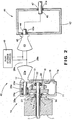
- Fig. 2 is a schematic diagram of the hydraulic power output unit 10 illustrated in Fig. 1 used together with a first embodiment of a hydraulic hybrid drive system, indicated generally at 40.
- the structure and manner of operation of the hydraulic power output unit 10 is substantially the same as described above with regard to Fig. 1 , with the exception that in the embodiment illustrated in Fig. 2 , the hydraulic power output unit 10 includes only a single one of the driven gears 24a, driveshafts 25a, bearing pairs 26a, and hydraulic pumps 27a.
- a cover 11a covers the fourth opening 18 formed through the second side of the housing 11.
- the hydraulic hybrid drive train 40 also includes a drive unit, indicated generally at 41.
- the drive unit 41 is spaced apart from the hydraulic power output unit 10 and is preferably located between a pair of opposed side rails of the frame of the vehicle.
- the drive unit 41 is generally conventional in the art and includes a housing 42 having opposed first and second sides.
- the drive unit 41 includes a hydraulic motor 43 that communicates through the lines 28a and 29a with the first hydraulic pump 27a of the hydraulic power output unit 10. By locating the hydraulic motor 43 on the first side of the housing 42 that is located nearest to the first hydraulic pump 27a of the hydraulic power output unit 10, the amount of fluid piping between the first hydraulic pump 27a and the hydraulic motor 43 can be minimized.
- the hydraulic motor 43 is directly supported on the housing of the drive unit 42, although such is not required. The purpose for and manner of operation of the hydraulic motor 43 will be explained below.
- the hydraulic motor 43 is adapted to rotatably drive a shaft 44 that extends through a first opening 45 formed through the first side of the drive unit 41 and, therefore, functions as an input shaft to the drive unit 41.
- the input shaft 44 of the drive unit 41 may be supported for rotation relative to the housing 42 by one or more bearings, such as shown at 45a within the first opening 45.
- the input shaft 44 of the drive unit 41 transfers rotational power to an output shaft 46 by any known means, as indicated by the dotted lines in Fig. 2 .
- rotational power can be transferred from the input shaft 44 of the drive unit 41 to the output shaft 46 either directly or by a plurality of gears (now shown) disposed within the housing 42 of the drive unit 41.
- the plurality of gears can provide either a single gear ratio or a plurality of user-selectable gear ratios between the input shaft 44 of the drive unit 41 and the output shaft 46.
- the output shaft 46 extends through a second opening 47 formed through the second side of the drive unit 41.
- the output shaft 46 may be supported for rotation relative to the housing 42 by one or more bearings, such as shown at 47a within the second opening 47.
- the output shaft 46 of the drive unit 41 may be co-axially aligned with the input shaft 20 of the hydraulic power output unit 10, although such is not required.
- the output shaft 46 is connected to rotatably drive one or more wheels (not shown) of a vehicle or other rotatably driven device.
- the hydraulic hybrid drive train 40 may also include one or more conventional fluid storage devices 48.
- the fluid storage devices 48 are conventional in the art and may, for example, include either or both of a low pressure reservoir and a high pressure accumulator.
- Fig. 2 schematically illustrates the fluid storage devices 48 in a location between the hydraulic power output unit 10 and the drive unit 40.
- low pressure hydraulic fluid is provided to the first hydraulic pump 27a of the hydraulic power output unit 10.
- the first hydraulic pump 27a supplies high pressure hydraulic fluid to the hydraulic motor 43 of the drive unit 40.
- the hydraulic motor 43 causes the input shaft 44 of the drive unit 41 to rotate, which, in turn, causes rotation of the output shaft 46 to drive the wheels of the vehicle.
- the first hydraulic pump 27a may pump hydraulic fluid into the high pressure accumulator of the fluid storage device 48, and fluid from that high pressure accumulator can be subsequently used to drive the hydraulic motor 43.
- the hybrid hydraulic drive train 40 may be adapted to recover and store energy during certain events, such as vehicle braking.
- the drive unit 41 is either adapted to include a hydraulic pumping unit (not shown) or the hydraulic motor 43 can be embodied as a conventional hydraulic pump/motor assembly.
- the pressurized fluid stored in the high pressure accumulator is supplied to the drive the hydraulic pump/motor assembly and, in turn, rotate the output shaft 118 and driven wheels of the vehicle.
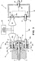
- Fig. 3 is a schematic diagram of the hydraulic power output unit 10 illustrated in Fig. 1 used together with a second embodiment of a hydraulic hybrid drive system, indicated generally at 50.
- the structure and manner of operation of the hydraulic power output unit 10 is substantially the same as described above with regard to Fig. 1 .
- the hydraulic hybrid drive train 50 also includes a drive unit, indicated generally at 51.
- the drive unit 51 is spaced apart from the hydraulic power output unit 10 and is preferably located between a pair of opposed side rails of the frame of the vehicle.
- the drive unit 51 is generally conventional in the art and includes a housing 52 having opposed first and second sides.
- the drive unit 51 includes a hydraulic motor 53 that communicates through the lines 28a and 29a with the first hydraulic pump 27a of the hydraulic power output unit 10. By locating the hydraulic motor 53 on the first side of the housing 52 that is located nearest to the first hydraulic pump 27a of the hydraulic power output unit 10, the amount of fluid piping between the first hydraulic pump 27a and the hydraulic motor 53 can be minimized.
- the hydraulic motor 53 is directly supported on the housing of the drive unit 52, although such is not required.
- the purpose for and manner of operation of the hydraulic motor 53 will be explained below.
- the hydraulic motor 53 is adapted to rotatably drive a first input shaft 54 to the drive unit 51.
- the first input shaft 54 to the drive unit 51 extends through a first opening 55 formed through the first side of the drive unit 51.
- the first input shaft 54 to the drive unit 51 may be supported for rotation relative to the housing 52 by one or more bearings, such as shown at 55a within the first opening 55.
- the second driveshaft 25b of the hydraulic power output unit 10 is not connected to rotatably drive the second hydraulic pump 27b. Rather, the second driveshaft 25b of the hydraulic power output unit 10 is connected to rotatably drive a second input shaft 56 to the drive unit 51.
- the second driveshaft 25b of the hydraulic power output unit 10 may be connected to rotatably drive the second input shaft 56 to the drive unit 51 by any conventional means such as, for example, a conventional driveshaft (indicated schematically at 56a) extending therebetween.
- a clutch (not shown) is provided such that the second driveshaft 25b of the hydraulic power output unit 10 is selectively engaged to rotatably drive the second input shaft 56 to the drive unit 51.
- Such a clutch may, for example, be provided as part of the hydraulic power output unit 10.
- the second input shaft 56 to the drive unit 51 extends through a second opening 57 formed through the first side of the drive unit 51.
- the second input shaft 56 to the drive unit 51 may be supported for rotation relative to the housing 52 by one or more bearings, such as shown at 57a within the first opening 57.
- the first input shaft 54 and the second input shaft 56 transfer rotational power to an output shaft 58 by any known means, as indicated by the dotted lines in Fig. 2 .
- a conventional clutching mechanism (not shown) may be provided within the housing 52 of the drive unit 51 such that either the first input shaft 54 or the second input shaft 56 is connected to transfer rotational power to the output shaft 58.
- Rotational power can be transferred from the selected one of the first input shaft 54 and the second input shaft 56 to the output shaft 58 either directly or by a plurality of gears (now shown) disposed within the housing 52 of the drive unit 51.
- the plurality of gears can provide either a single gear ratio or a plurality of user-selectable gear ratios between the first input shaft 54 and the second input shaft 56 and the output shaft 58.
- the output shaft 58 extends through a second opening 59 formed through the second side of the drive unit 51.
- the output shaft 58 may be supported for rotation relative to the housing 52 by one or more bearings, such as shown at 59a within the second opening 59.
- the output shaft 58 of the drive unit 51 may be co-axially aligned with the input shaft 20 of the hydraulic power output unit 10, although such is not required.
- the output shaft 58 is connected to rotatably drive one or more wheels (not shown) of a vehicle or other rotatably driven device.
- the hydraulic hybrid drive train 50 may also include one or more conventional fluid storage devices 60.
- the fluid storage devices 60 are conventional in the art and may, for example, include either or both of a low pressure reservoir and a high pressure accumulator.
- Fig. 3 schematically illustrates the fluid storage devices 60 in a location between the hydraulic power output unit 10 and the drive unit 50.
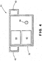
- Fig. 4 is a schematic end elevational view of the first side of the drive unit 51 illustrated in Fig. 3 .
- the drive unit 51 may further include an optional pump/motor 61 in addition to the hydraulic motor 53.
- the pump/motor 61 may function as either a pump, a motor, or both a pump and a motor for providing fluid to the fluid storage devices 60 or using fluid from either the first hydraulic pump 27a or the fluid storage devices 60.
- the driveshaft 56a that extends between the second driveshaft 25b of the hydraulic power output unit 10 and the second input shaft 56 to the drive unit 51 can be offset relative to rotational axes of the input shaft 20 driveshaft 22.
- This offsetting of the driveshaft 56a enables the drive unit 51 to be more compact, while still having both a mechanical connection to the second driveshaft 25b of the hydraulic power output unit 10 and at least one hydraulic motor 53.
- this compactness of the drive unit 102 enables the drive unit to be located between the opposed side rails 62 of the frame of the vehicle.
- the embodiment illustrated in Figs. 3 and 4 may operate in a manner that is similar to that of Fig. 2 , with the addition of providing a direct drive mode for driving the wheels of the vehicle through input shaft 20, the second driveshaft 25b, the driveshaft 56a, and the output shaft 58.
Landscapes
- Engineering & Computer Science (AREA)
- Mechanical Engineering (AREA)
- General Engineering & Computer Science (AREA)
- Chemical & Material Sciences (AREA)
- Combustion & Propulsion (AREA)
- Transportation (AREA)
- Arrangement And Driving Of Transmission Devices (AREA)
- Motor Power Transmission Devices (AREA)
- Hybrid Electric Vehicles (AREA)
- Auxiliary Drives, Propulsion Controls, And Safety Devices (AREA)
Claims (9)
- Unité de production de puissance hydraulique (10) comprenant :un logement (11) ;un arbre d'entrée (20) qui s'étend à l'intérieur du logement (11) et est adapté à être entraîné en rotation par une source de puissance de rotation ; etcaractérisée par une roue menante (23) qui est supportée sur l'arbre d'entrée (20) pour une rotation avec celui-ci ; une première roue menée (24a) qui est entraînée en rotation par la roue menante (23) et est supportée sur un premier arbre de transmission (25a) de manière à entraîner en rotation une première pompe hydraulique (27a) pour pomper un fluide hydraulique ;une seconde roue menée (24b) qui est entraînée en rotation par la roue menante (23) et est supportée sur un second arbre de transmission (25b) de manière à entraîner en rotation une seconde pompe hydraulique (27b) pour pomper un fluide hydraulique ; etun amortisseur de vibrations (30) disposé à l'intérieur du logement pour amortir les vibrations dans l'arbre d'entrée (20).
- Unité de production de puissance hydraulique définie dans la revendication 1 dans laquelle l'amortisseur de vibrations (30) est supporté sur l'arbre d'entrée (23) pour une rotation avec celui-ci.
- Unité de production de puissance hydraulique définie dans la revendication 2 dans laquelle l'amortisseur de vibrations (30) est claveté sur l'arbre d'entrée (23).
- Ensemble d'unité de production de puissance hydraulique et d'unité d'entraînement comprenant :l'unité de production de puissance hydraulique (10) définie dans la revendication 1 ; et une unité d'entraînement (41) comprenant un arbre d'entrée (44), un moteur hydraulique (43) qui est entraîné en rotation par la pompe hydraulique (27a/27b) de l'unité de production de puissance hydraulique et entraîne en rotation l'arbre d'entrée de l'unité d'entraînement, et un arbre de sortie (46) qui est entraîné en rotation par l'arbre d'entrée de l'unité d'entraînement.
- Ensemble d'unité de production de puissance hydraulique et d'unité d'entraînement défini dans la revendication 4 dans lequel l'amortisseur de vibrations (30) est supporté sur l'arbre d'entrée (20) de l'unité de production de puissance hydraulique (10) pour une rotation avec celui-ci.
- Ensemble d'unité de production de puissance hydraulique et d'unité d'entraînement défini dans la revendication 5 dans lequel l'amortisseur de vibrations (30) est claveté sur l'arbre d'entrée (20) de l'unité de production de puissance hydraulique (10).
- Unité de production de puissance hydraulique définie dans la revendication 4 dans laquelle l'arbre d'entrée dans l'unité d'entraînement (51) est un premier arbre d'entrée (54), et dans laquelle l'unité d'entraînement comprend en outre un second arbre d'entrée (56), l'arbre de sortie (58) étant sélectivement entraîné en rotation soit par le premier arbre d'entrée, soit par le second arbre d'entrée.
- Ensemble d'unité de production de puissance hydraulique et d'unité d'entraînement défini dans la revendication 7 dans lequel l'unité de production de puissance hydraulique (10) comprend en outre une roue menante (23) qui est supportée sur l'arbre d'entrée pour une rotation avec celui-ci, une première roue menée (24a) qui est entraînée en rotation par la roue menante et est supportée sur un premier arbre de transmission (25a) pour une rotation avec celui-ci de manière à entraîner en rotation la première pompe hydraulique (27a), et une seconde roue menée (24b) qui est entraînée en rotation par la roue menante et est supportée sur un second arbre de transmission (25b) pour une rotation avec celui-ci, le second arbre de transmission de l'unité de production de puissance hydraulique entraînant en rotation le second arbre d'entrée (56) de l'unité d'entraînement (51).
- Ensemble d'unité de production de puissance hydraulique et d'unité d'entraînement comprenant :l'unité de production de puissance hydraulique définie dans la revendication 1 ; etune unité d'entraînement (51) comprenant un arbre d'entrée (54), un premier moteur hydraulique (53) qui est entraîné en rotation par la première pompe hydraulique (27a) de l'unité de production de puissance hydraulique (10) et entraîne en rotation l'arbre d'entrée de l'unité d'entraînement, un second moteur hydraulique qui est entraîné en rotation par la seconde pompe hydraulique (27b) de l'unité de production de puissance hydraulique et entraîne en rotation l'arbre d'entrée de l'unité d'entraînement, et un arbre de sortie (58) qui est entraîné en rotation par l'arbre d'entrée de l'unité d'entraînement.
Applications Claiming Priority (2)
| Application Number | Priority Date | Filing Date | Title |
|---|---|---|---|
| US1854008P | 2008-01-02 | 2008-01-02 | |
| PCT/US2009/030001 WO2009089079A2 (fr) | 2008-01-02 | 2009-01-02 | Unité de production de puissance hydraulique et système d'entraînement hybride hydraulique comprenant celle-ci |
Publications (3)
| Publication Number | Publication Date |
|---|---|
| EP2240340A2 EP2240340A2 (fr) | 2010-10-20 |
| EP2240340A4 EP2240340A4 (fr) | 2013-07-17 |
| EP2240340B1 true EP2240340B1 (fr) | 2016-05-04 |
Family
ID=40853707
Family Applications (1)
| Application Number | Title | Priority Date | Filing Date |
|---|---|---|---|
| EP09701463.3A Not-in-force EP2240340B1 (fr) | 2008-01-02 | 2009-01-02 | Unité de production de puissance hydraulique et système d'entraînement hybride hydraulique comprenant celle-ci |
Country Status (4)
| Country | Link |
|---|---|
| US (1) | US8505413B2 (fr) |
| EP (1) | EP2240340B1 (fr) |
| ES (1) | ES2583955T3 (fr) |
| WO (1) | WO2009089079A2 (fr) |
Families Citing this family (2)
| Publication number | Priority date | Publication date | Assignee | Title |
|---|---|---|---|---|
| US9435355B2 (en) | 2012-06-29 | 2016-09-06 | Eaton Corporation | Hydraulic launch assist system |
| FR3008933B1 (fr) * | 2013-07-23 | 2017-05-12 | Technoboost | Procede de limitation des vibrations sur un vehicule hybride hydraulique |
Family Cites Families (32)
| Publication number | Priority date | Publication date | Assignee | Title |
|---|---|---|---|---|
| US4134310A (en) * | 1977-04-15 | 1979-01-16 | Orshansky Transmission Corporation | Hydromechanical transmission with hydrodynamic drive |
| DE2757191C2 (de) * | 1977-12-22 | 1983-01-13 | Zahnradfabrik Friedrichshafen Ag, 7990 Friedrichshafen | Stufenlos einstellbares hydrostatisch-mechanisches Verbundgetriebe |
| DE2950619A1 (de) * | 1979-12-15 | 1981-06-19 | M.A.N. Maschinenfabrik Augsburg-Nürnberg AG, 8000 München | Leistungsverzweigungsgetriebe mit einem planetendifferentialgetriebe |
| JPS58141934A (ja) * | 1982-02-17 | 1983-08-23 | Komatsu Ltd | 油圧機械式変速及び操向機の変速制御方法 |
| FR2527288B1 (fr) * | 1982-05-19 | 1987-10-09 | Renault Vehicules Ind | Dispositif oleopneumatique de recuperation d'energie de freinage pour vehicule urbain |
| US4485691A (en) * | 1982-08-26 | 1984-12-04 | General Electric Company | Simplified hydromechanical steering transmission |
| CA1305017C (fr) * | 1987-10-20 | 1992-07-14 | Hideo Koyama | Transmission hydraulique a reglage continu equipee d'une commande directe del'embrayage a fluide |
| DE3938080A1 (de) | 1989-11-16 | 1991-05-23 | Man Nutzfahrzeuge Ag | Antriebseinrichtung in einem omnibus |
| US5683322A (en) * | 1993-04-21 | 1997-11-04 | Meyerle; Michael | Continuous hydrostatic-mechanical branch power split transmission particularly for power vehicles |
| DE4323602A1 (de) | 1993-07-09 | 1995-01-12 | Mannesmann Ag | Antriebsanordnung für ein Hybridfahrzeug |
| DE4404829C2 (de) * | 1994-02-16 | 1996-11-28 | Detlef Tolksdorf | Hydrostatisch mechanisches Lastschaltgetriebe, insbesondere für mobile Bau- und Arbeitsmaschinen, sowie Verfahren zur Steuerung eines Lastschaltgetriebes |
| US5495912A (en) | 1994-06-03 | 1996-03-05 | The United States Of America As Represented By The Administrator Of The U.S. Environmental Protection Agency | Hybrid powertrain vehicle |
| US5607027A (en) | 1995-04-28 | 1997-03-04 | Anser, Inc. | Hydraulic drive system for a vehicle |
| US5971092A (en) | 1995-08-16 | 1999-10-26 | Frank H. Walker | Vehicle drive system featuring split engine and accessory back drive |
| JP2981980B2 (ja) * | 1996-02-22 | 1999-11-22 | 本田技研工業株式会社 | 油圧・機械式伝動装置 |
| IT1284483B1 (it) * | 1996-09-03 | 1998-05-21 | Ingersoll Rand Italiana S P A | Apparecchiatura di trasmissione del moto di tipo idrostatico-meccanico particolarmente cambio idromeccanico per macchine e veicoli |
| DE19808731C2 (de) * | 1998-03-02 | 1999-12-23 | Mannesmann Sachs Ag | Drehschwingungsdämpfer |
| DE10036504B4 (de) | 1999-08-02 | 2011-05-19 | Schaeffler Technologies Gmbh & Co. Kg | Antriebsstrang |
| US6719080B1 (en) | 2000-01-10 | 2004-04-13 | The United States Of America As Represented By The Administrator Of The Environmental Protection Agency | Hydraulic hybrid vehicle |
| US7337869B2 (en) | 2000-01-10 | 2008-03-04 | The United States Of America As Represented By The Administrator Of The United States Environmental Protection Agency | Hydraulic hybrid vehicle with integrated hydraulic drive module and four-wheel-drive, and method of operation thereof |
| DE10108368C1 (de) * | 2001-02-21 | 2002-11-07 | Walterscheid Gmbh Gkn | Antriebsanordnung für allradgetriebene Fahrzeuge |
| US6875113B2 (en) * | 2001-09-26 | 2005-04-05 | Eagle-Picher Industries, Inc. | Torsional vibration damper |
| WO2004060708A1 (fr) | 2003-01-04 | 2004-07-22 | Ford Global Technologies, Llc | Groupe motopropulseur hybride alimente a l'hydrogene et vehicule |
| US7093679B1 (en) * | 2003-06-05 | 2006-08-22 | Watson Incorporated | Foundation drilling apparatus and method with continuously variable hydraulic differential rotary table |
| US7100723B2 (en) | 2004-02-01 | 2006-09-05 | Ford Global Technologies, Llc | Multiple pressure mode operation for hydraulic hybrid vehicle powertrain |
| US7082757B2 (en) | 2004-07-01 | 2006-08-01 | Ford Global Technologies, Llc | Pump/motor operating mode switching control for hydraulic hybrid vehicle |
| US7232192B2 (en) | 2004-07-01 | 2007-06-19 | Ford Global Technologies, Llc | Deadband regenerative braking control for hydraulic hybrid vehicle powertrain |
| US7147078B2 (en) | 2004-07-01 | 2006-12-12 | Ford Global Technologies, Llc | Charging a fluid accumulator while operating a hybrid vehicle powertrain including an engine and a pump/motor |
| US7147239B2 (en) | 2004-07-01 | 2006-12-12 | Ford Global Technologies, Llc | Wheel creep control of hydraulic hybrid vehicle using regenerative braking |
| US7273122B2 (en) | 2004-09-30 | 2007-09-25 | Bosch Rexroth Corporation | Hybrid hydraulic drive system with engine integrated hydraulic machine |
| US7793496B2 (en) | 2004-11-22 | 2010-09-14 | William Hugh Salvin Rampen | Infinitely variable transmission hydraulic hybrid for on and off highway vehicles |
| CN101037087A (zh) * | 2006-03-14 | 2007-09-19 | 朱荣辉 | 一种机动车无级变速混合动力节能装置 |
-
2009
- 2009-01-02 ES ES09701463.3T patent/ES2583955T3/es active Active
- 2009-01-02 WO PCT/US2009/030001 patent/WO2009089079A2/fr active Application Filing
- 2009-01-02 EP EP09701463.3A patent/EP2240340B1/fr not_active Not-in-force
- 2009-01-02 US US12/348,089 patent/US8505413B2/en not_active Expired - Fee Related
Also Published As
| Publication number | Publication date |
|---|---|
| ES2583955T3 (es) | 2016-09-23 |
| WO2009089079A2 (fr) | 2009-07-16 |
| US20090260353A1 (en) | 2009-10-22 |
| EP2240340A4 (fr) | 2013-07-17 |
| WO2009089079A3 (fr) | 2009-10-15 |
| EP2240340A2 (fr) | 2010-10-20 |
| US8505413B2 (en) | 2013-08-13 |
Similar Documents
| Publication | Publication Date | Title |
|---|---|---|
| US7143858B2 (en) | Transmission for a working vehicle and vehicle | |
| JP5318387B2 (ja) | ドライブトレーン用アクスルドライブユニット | |
| JP2002154343A (ja) | 前後輪駆動車両の動力伝達機構 | |
| KR102372142B1 (ko) | 농업용 작업차의 동력전달장치 | |
| CA2924564C (fr) | Module de groupe propulseur | |
| JPH0611013A (ja) | 液圧・機械式駆動システム | |
| US5052987A (en) | Stepless hydrostatic-mechanical transmission | |
| EP2954229B1 (fr) | Prise de force ayant un bruit d'engrenage réduit | |
| JPH07242130A (ja) | 作業用車両の走行駆動装置 | |
| EP2240340B1 (fr) | Unité de production de puissance hydraulique et système d'entraînement hybride hydraulique comprenant celle-ci | |
| CN110087931A (zh) | 动力输出装置及其部件 | |
| JP5077784B2 (ja) | 駆動力分配を制御可能な自動車用差動歯車装置ユニット | |
| JP3691779B2 (ja) | 四輪駆動車両の動力伝達機構 | |
| US8083634B2 (en) | Disk brake, planet transmission, drive device and work vehicle | |
| US8596165B2 (en) | Multiple gear motor drive | |
| FR2885980A1 (fr) | Boite de vitesse avec pompe a huile laterale | |
| JP6292194B2 (ja) | パワートレインユニット | |
| JPH02285111A (ja) | 土工機械用駆動装置 | |
| KR101857713B1 (ko) | 동력인출장치 일체형 hst용 지지장치 | |
| JP2000289478A (ja) | 作業車両のミッションケース | |
| KR101982179B1 (ko) | 동력인출장치 일체형 hst용 지지장치 | |
| US20060160649A1 (en) | Fluid pump for a transmission | |
| JP2531027B2 (ja) | クラッチ付フライホイ―ル動力取出し装置 | |
| JPH05330459A (ja) | トラクター | |
| JPH0518458A (ja) | 作業車 |
Legal Events
| Date | Code | Title | Description |
|---|---|---|---|
| PUAI | Public reference made under article 153(3) epc to a published international application that has entered the european phase |
Free format text: ORIGINAL CODE: 0009012 |
|
| 17P | Request for examination filed |
Effective date: 20100726 |
|
| AK | Designated contracting states |
Kind code of ref document: A2 Designated state(s): AT BE BG CH CY CZ DE DK EE ES FI FR GB GR HR HU IE IS IT LI LT LU LV MC MK MT NL NO PL PT RO SE SI SK TR |
|
| AX | Request for extension of the european patent |
Extension state: AL BA RS |
|
| DAX | Request for extension of the european patent (deleted) | ||
| A4 | Supplementary search report drawn up and despatched |
Effective date: 20130617 |
|
| RIC1 | Information provided on ipc code assigned before grant |
Ipc: F16H 47/02 20060101ALI20130611BHEP Ipc: B60K 17/04 20060101ALI20130611BHEP Ipc: B60K 17/10 20060101AFI20130611BHEP |
|
| 17Q | First examination report despatched |
Effective date: 20140806 |
|
| GRAP | Despatch of communication of intention to grant a patent |
Free format text: ORIGINAL CODE: EPIDOSNIGR1 |
|
| INTG | Intention to grant announced |
Effective date: 20160122 |
|
| GRAS | Grant fee paid |
Free format text: ORIGINAL CODE: EPIDOSNIGR3 |
|
| GRAA | (expected) grant |
Free format text: ORIGINAL CODE: 0009210 |
|
| AK | Designated contracting states |
Kind code of ref document: B1 Designated state(s): AT BE BG CH CY CZ DE DK EE ES FI FR GB GR HR HU IE IS IT LI LT LU LV MC MK MT NL NO PL PT RO SE SI SK TR |
|
| REG | Reference to a national code |
Ref country code: GB Ref legal event code: FG4D |
|
| REG | Reference to a national code |
Ref country code: CH Ref legal event code: EP |
|
| REG | Reference to a national code |
Ref country code: AT Ref legal event code: REF Ref document number: 796585 Country of ref document: AT Kind code of ref document: T Effective date: 20160515 |
|
| REG | Reference to a national code |
Ref country code: IE Ref legal event code: FG4D |
|
| REG | Reference to a national code |
Ref country code: DE Ref legal event code: R096 Ref document number: 602009038350 Country of ref document: DE |
|
| REG | Reference to a national code |
Ref country code: NL Ref legal event code: MP Effective date: 20160504 |
|
| REG | Reference to a national code |
Ref country code: LT Ref legal event code: MG4D |
|
| REG | Reference to a national code |
Ref country code: ES Ref legal event code: FG2A Ref document number: 2583955 Country of ref document: ES Kind code of ref document: T3 Effective date: 20160923 |
|
| PG25 | Lapsed in a contracting state [announced via postgrant information from national office to epo] |
Ref country code: FI Free format text: LAPSE BECAUSE OF FAILURE TO SUBMIT A TRANSLATION OF THE DESCRIPTION OR TO PAY THE FEE WITHIN THE PRESCRIBED TIME-LIMIT Effective date: 20160504 Ref country code: NO Free format text: LAPSE BECAUSE OF FAILURE TO SUBMIT A TRANSLATION OF THE DESCRIPTION OR TO PAY THE FEE WITHIN THE PRESCRIBED TIME-LIMIT Effective date: 20160804 Ref country code: NL Free format text: LAPSE BECAUSE OF FAILURE TO SUBMIT A TRANSLATION OF THE DESCRIPTION OR TO PAY THE FEE WITHIN THE PRESCRIBED TIME-LIMIT Effective date: 20160504 Ref country code: LT Free format text: LAPSE BECAUSE OF FAILURE TO SUBMIT A TRANSLATION OF THE DESCRIPTION OR TO PAY THE FEE WITHIN THE PRESCRIBED TIME-LIMIT Effective date: 20160504 |
|
| REG | Reference to a national code |
Ref country code: AT Ref legal event code: MK05 Ref document number: 796585 Country of ref document: AT Kind code of ref document: T Effective date: 20160504 |
|
| PG25 | Lapsed in a contracting state [announced via postgrant information from national office to epo] |
Ref country code: GR Free format text: LAPSE BECAUSE OF FAILURE TO SUBMIT A TRANSLATION OF THE DESCRIPTION OR TO PAY THE FEE WITHIN THE PRESCRIBED TIME-LIMIT Effective date: 20160805 Ref country code: SE Free format text: LAPSE BECAUSE OF FAILURE TO SUBMIT A TRANSLATION OF THE DESCRIPTION OR TO PAY THE FEE WITHIN THE PRESCRIBED TIME-LIMIT Effective date: 20160504 Ref country code: LV Free format text: LAPSE BECAUSE OF FAILURE TO SUBMIT A TRANSLATION OF THE DESCRIPTION OR TO PAY THE FEE WITHIN THE PRESCRIBED TIME-LIMIT Effective date: 20160504 Ref country code: PT Free format text: LAPSE BECAUSE OF FAILURE TO SUBMIT A TRANSLATION OF THE DESCRIPTION OR TO PAY THE FEE WITHIN THE PRESCRIBED TIME-LIMIT Effective date: 20160905 Ref country code: HR Free format text: LAPSE BECAUSE OF FAILURE TO SUBMIT A TRANSLATION OF THE DESCRIPTION OR TO PAY THE FEE WITHIN THE PRESCRIBED TIME-LIMIT Effective date: 20160504 |
|
| REG | Reference to a national code |
Ref country code: FR Ref legal event code: PLFP Year of fee payment: 9 |
|
| PG25 | Lapsed in a contracting state [announced via postgrant information from national office to epo] |
Ref country code: SK Free format text: LAPSE BECAUSE OF FAILURE TO SUBMIT A TRANSLATION OF THE DESCRIPTION OR TO PAY THE FEE WITHIN THE PRESCRIBED TIME-LIMIT Effective date: 20160504 Ref country code: DK Free format text: LAPSE BECAUSE OF FAILURE TO SUBMIT A TRANSLATION OF THE DESCRIPTION OR TO PAY THE FEE WITHIN THE PRESCRIBED TIME-LIMIT Effective date: 20160504 Ref country code: CZ Free format text: LAPSE BECAUSE OF FAILURE TO SUBMIT A TRANSLATION OF THE DESCRIPTION OR TO PAY THE FEE WITHIN THE PRESCRIBED TIME-LIMIT Effective date: 20160504 Ref country code: RO Free format text: LAPSE BECAUSE OF FAILURE TO SUBMIT A TRANSLATION OF THE DESCRIPTION OR TO PAY THE FEE WITHIN THE PRESCRIBED TIME-LIMIT Effective date: 20160504 Ref country code: EE Free format text: LAPSE BECAUSE OF FAILURE TO SUBMIT A TRANSLATION OF THE DESCRIPTION OR TO PAY THE FEE WITHIN THE PRESCRIBED TIME-LIMIT Effective date: 20160504 |
|
| REG | Reference to a national code |
Ref country code: DE Ref legal event code: R097 Ref document number: 602009038350 Country of ref document: DE |
|
| PG25 | Lapsed in a contracting state [announced via postgrant information from national office to epo] |
Ref country code: AT Free format text: LAPSE BECAUSE OF FAILURE TO SUBMIT A TRANSLATION OF THE DESCRIPTION OR TO PAY THE FEE WITHIN THE PRESCRIBED TIME-LIMIT Effective date: 20160504 Ref country code: BE Free format text: LAPSE BECAUSE OF FAILURE TO SUBMIT A TRANSLATION OF THE DESCRIPTION OR TO PAY THE FEE WITHIN THE PRESCRIBED TIME-LIMIT Effective date: 20160504 Ref country code: PL Free format text: LAPSE BECAUSE OF FAILURE TO SUBMIT A TRANSLATION OF THE DESCRIPTION OR TO PAY THE FEE WITHIN THE PRESCRIBED TIME-LIMIT Effective date: 20160504 |
|
| PLBE | No opposition filed within time limit |
Free format text: ORIGINAL CODE: 0009261 |
|
| STAA | Information on the status of an ep patent application or granted ep patent |
Free format text: STATUS: NO OPPOSITION FILED WITHIN TIME LIMIT |
|
| 26N | No opposition filed |
Effective date: 20170207 |
|
| PGFP | Annual fee paid to national office [announced via postgrant information from national office to epo] |
Ref country code: DE Payment date: 20170125 Year of fee payment: 9 Ref country code: FR Payment date: 20170125 Year of fee payment: 9 |
|
| PG25 | Lapsed in a contracting state [announced via postgrant information from national office to epo] |
Ref country code: SI Free format text: LAPSE BECAUSE OF FAILURE TO SUBMIT A TRANSLATION OF THE DESCRIPTION OR TO PAY THE FEE WITHIN THE PRESCRIBED TIME-LIMIT Effective date: 20160504 |
|
| PGFP | Annual fee paid to national office [announced via postgrant information from national office to epo] |
Ref country code: GB Payment date: 20170127 Year of fee payment: 9 |
|
| PGFP | Annual fee paid to national office [announced via postgrant information from national office to epo] |
Ref country code: IT Payment date: 20170124 Year of fee payment: 9 Ref country code: ES Payment date: 20170126 Year of fee payment: 9 |
|
| REG | Reference to a national code |
Ref country code: CH Ref legal event code: PL |
|
| PG25 | Lapsed in a contracting state [announced via postgrant information from national office to epo] |
Ref country code: MC Free format text: LAPSE BECAUSE OF FAILURE TO SUBMIT A TRANSLATION OF THE DESCRIPTION OR TO PAY THE FEE WITHIN THE PRESCRIBED TIME-LIMIT Effective date: 20160504 |
|
| PG25 | Lapsed in a contracting state [announced via postgrant information from national office to epo] |
Ref country code: CH Free format text: LAPSE BECAUSE OF NON-PAYMENT OF DUE FEES Effective date: 20170131 Ref country code: LI Free format text: LAPSE BECAUSE OF NON-PAYMENT OF DUE FEES Effective date: 20170131 |
|
| REG | Reference to a national code |
Ref country code: IE Ref legal event code: MM4A |
|
| PG25 | Lapsed in a contracting state [announced via postgrant information from national office to epo] |
Ref country code: LU Free format text: LAPSE BECAUSE OF NON-PAYMENT OF DUE FEES Effective date: 20170102 |
|
| PG25 | Lapsed in a contracting state [announced via postgrant information from national office to epo] |
Ref country code: IE Free format text: LAPSE BECAUSE OF NON-PAYMENT OF DUE FEES Effective date: 20170102 |
|
| REG | Reference to a national code |
Ref country code: DE Ref legal event code: R119 Ref document number: 602009038350 Country of ref document: DE |
|
| GBPC | Gb: european patent ceased through non-payment of renewal fee |
Effective date: 20180102 |
|
| PG25 | Lapsed in a contracting state [announced via postgrant information from national office to epo] |
Ref country code: MT Free format text: LAPSE BECAUSE OF NON-PAYMENT OF DUE FEES Effective date: 20170102 |
|
| PG25 | Lapsed in a contracting state [announced via postgrant information from national office to epo] |
Ref country code: DE Free format text: LAPSE BECAUSE OF NON-PAYMENT OF DUE FEES Effective date: 20180801 Ref country code: FR Free format text: LAPSE BECAUSE OF NON-PAYMENT OF DUE FEES Effective date: 20180131 |
|
| REG | Reference to a national code |
Ref country code: FR Ref legal event code: ST Effective date: 20180928 |
|
| PG25 | Lapsed in a contracting state [announced via postgrant information from national office to epo] |
Ref country code: GB Free format text: LAPSE BECAUSE OF NON-PAYMENT OF DUE FEES Effective date: 20180102 |
|
| PG25 | Lapsed in a contracting state [announced via postgrant information from national office to epo] |
Ref country code: IT Free format text: LAPSE BECAUSE OF NON-PAYMENT OF DUE FEES Effective date: 20180102 |
|
| PG25 | Lapsed in a contracting state [announced via postgrant information from national office to epo] |
Ref country code: HU Free format text: LAPSE BECAUSE OF FAILURE TO SUBMIT A TRANSLATION OF THE DESCRIPTION OR TO PAY THE FEE WITHIN THE PRESCRIBED TIME-LIMIT; INVALID AB INITIO Effective date: 20090102 |
|
| REG | Reference to a national code |
Ref country code: ES Ref legal event code: FD2A Effective date: 20190730 |
|
| PG25 | Lapsed in a contracting state [announced via postgrant information from national office to epo] |
Ref country code: BG Free format text: LAPSE BECAUSE OF FAILURE TO SUBMIT A TRANSLATION OF THE DESCRIPTION OR TO PAY THE FEE WITHIN THE PRESCRIBED TIME-LIMIT Effective date: 20160504 |
|
| PG25 | Lapsed in a contracting state [announced via postgrant information from national office to epo] |
Ref country code: ES Free format text: LAPSE BECAUSE OF NON-PAYMENT OF DUE FEES Effective date: 20180103 Ref country code: CY Free format text: LAPSE BECAUSE OF NON-PAYMENT OF DUE FEES Effective date: 20160504 |
|
| PG25 | Lapsed in a contracting state [announced via postgrant information from national office to epo] |
Ref country code: MK Free format text: LAPSE BECAUSE OF FAILURE TO SUBMIT A TRANSLATION OF THE DESCRIPTION OR TO PAY THE FEE WITHIN THE PRESCRIBED TIME-LIMIT Effective date: 20160504 |
|
| PG25 | Lapsed in a contracting state [announced via postgrant information from national office to epo] |
Ref country code: TR Free format text: LAPSE BECAUSE OF FAILURE TO SUBMIT A TRANSLATION OF THE DESCRIPTION OR TO PAY THE FEE WITHIN THE PRESCRIBED TIME-LIMIT Effective date: 20160504 |
|
| PG25 | Lapsed in a contracting state [announced via postgrant information from national office to epo] |
Ref country code: IS Free format text: LAPSE BECAUSE OF FAILURE TO SUBMIT A TRANSLATION OF THE DESCRIPTION OR TO PAY THE FEE WITHIN THE PRESCRIBED TIME-LIMIT Effective date: 20160904 |