EP2238337B1 - Brennstoffeinspritzventil - Google Patents
Brennstoffeinspritzventil Download PDFInfo
- Publication number
- EP2238337B1 EP2238337B1 EP08865539.4A EP08865539A EP2238337B1 EP 2238337 B1 EP2238337 B1 EP 2238337B1 EP 08865539 A EP08865539 A EP 08865539A EP 2238337 B1 EP2238337 B1 EP 2238337B1
- Authority
- EP
- European Patent Office
- Prior art keywords
- valve
- fuel injection
- injection valve
- ejection openings
- sleeve
- Prior art date
- Legal status (The legal status is an assumption and is not a legal conclusion. Google has not performed a legal analysis and makes no representation as to the accuracy of the status listed.)
- Not-in-force
Links
Images

Classifications
-
- F—MECHANICAL ENGINEERING; LIGHTING; HEATING; WEAPONS; BLASTING
- F02—COMBUSTION ENGINES; HOT-GAS OR COMBUSTION-PRODUCT ENGINE PLANTS
- F02M—SUPPLYING COMBUSTION ENGINES IN GENERAL WITH COMBUSTIBLE MIXTURES OR CONSTITUENTS THEREOF
- F02M61/00—Fuel-injectors not provided for in groups F02M39/00 - F02M57/00 or F02M67/00
- F02M61/16—Details not provided for in, or of interest apart from, the apparatus of groups F02M61/02 - F02M61/14
- F02M61/18—Injection nozzles, e.g. having valve seats; Details of valve member seated ends, not otherwise provided for
- F02M61/1806—Injection nozzles, e.g. having valve seats; Details of valve member seated ends, not otherwise provided for characterised by the arrangement of discharge orifices, e.g. orientation or size
- F02M61/184—Discharge orifices having non circular sections
-
- F—MECHANICAL ENGINEERING; LIGHTING; HEATING; WEAPONS; BLASTING
- F02—COMBUSTION ENGINES; HOT-GAS OR COMBUSTION-PRODUCT ENGINE PLANTS
- F02M—SUPPLYING COMBUSTION ENGINES IN GENERAL WITH COMBUSTIBLE MIXTURES OR CONSTITUENTS THEREOF
- F02M61/00—Fuel-injectors not provided for in groups F02M39/00 - F02M57/00 or F02M67/00
- F02M61/04—Fuel-injectors not provided for in groups F02M39/00 - F02M57/00 or F02M67/00 having valves, e.g. having a plurality of valves in series
- F02M61/042—The valves being provided with fuel passages
-
- F—MECHANICAL ENGINEERING; LIGHTING; HEATING; WEAPONS; BLASTING
- F02—COMBUSTION ENGINES; HOT-GAS OR COMBUSTION-PRODUCT ENGINE PLANTS
- F02M—SUPPLYING COMBUSTION ENGINES IN GENERAL WITH COMBUSTIBLE MIXTURES OR CONSTITUENTS THEREOF
- F02M61/00—Fuel-injectors not provided for in groups F02M39/00 - F02M57/00 or F02M67/00
- F02M61/04—Fuel-injectors not provided for in groups F02M39/00 - F02M57/00 or F02M67/00 having valves, e.g. having a plurality of valves in series
- F02M61/10—Other injectors with elongated valve bodies, i.e. of needle-valve type
- F02M61/12—Other injectors with elongated valve bodies, i.e. of needle-valve type characterised by the provision of guiding or centring means for valve bodies
-
- F—MECHANICAL ENGINEERING; LIGHTING; HEATING; WEAPONS; BLASTING
- F02—COMBUSTION ENGINES; HOT-GAS OR COMBUSTION-PRODUCT ENGINE PLANTS
- F02M—SUPPLYING COMBUSTION ENGINES IN GENERAL WITH COMBUSTIBLE MIXTURES OR CONSTITUENTS THEREOF
- F02M61/00—Fuel-injectors not provided for in groups F02M39/00 - F02M57/00 or F02M67/00
- F02M61/04—Fuel-injectors not provided for in groups F02M39/00 - F02M57/00 or F02M67/00 having valves, e.g. having a plurality of valves in series
- F02M61/10—Other injectors with elongated valve bodies, i.e. of needle-valve type
-
- F—MECHANICAL ENGINEERING; LIGHTING; HEATING; WEAPONS; BLASTING
- F02—COMBUSTION ENGINES; HOT-GAS OR COMBUSTION-PRODUCT ENGINE PLANTS
- F02M—SUPPLYING COMBUSTION ENGINES IN GENERAL WITH COMBUSTIBLE MIXTURES OR CONSTITUENTS THEREOF
- F02M61/00—Fuel-injectors not provided for in groups F02M39/00 - F02M57/00 or F02M67/00
- F02M61/16—Details not provided for in, or of interest apart from, the apparatus of groups F02M61/02 - F02M61/14
- F02M61/165—Filtering elements specially adapted in fuel inlets to injector
-
- F—MECHANICAL ENGINEERING; LIGHTING; HEATING; WEAPONS; BLASTING
- F02—COMBUSTION ENGINES; HOT-GAS OR COMBUSTION-PRODUCT ENGINE PLANTS
- F02M—SUPPLYING COMBUSTION ENGINES IN GENERAL WITH COMBUSTIBLE MIXTURES OR CONSTITUENTS THEREOF
- F02M61/00—Fuel-injectors not provided for in groups F02M39/00 - F02M57/00 or F02M67/00
- F02M61/16—Details not provided for in, or of interest apart from, the apparatus of groups F02M61/02 - F02M61/14
- F02M61/168—Assembling; Disassembling; Manufacturing; Adjusting
Definitions
- the invention relates to a fuel injection valve according to the preamble of the main claim.
- a fuel injection valve is already known, in which a perforated disc is provided downstream of the valve seat surface, which has a plurality of injection openings.
- the especiallyigerweise ten to twenty spray orifices are located in a plane of the perforated disc, which is perpendicular to the valve longitudinal axis.
- the largest part of the ejection openings is obliquely or inclined introduced into the perforated disc, so that the opening axes of the ejection openings have no parallelism to the valve longitudinal axis. Since the inclinations of the ejection openings can be chosen differently, a divergence of the individual jets to be sprayed is easily achievable.
- the ejection openings are introduced, for example, by laser drilling in the perforated disk in a largely uniform size.
- the fuel injector is particularly suitable for fuel injection systems of mixture-compression spark-ignition internal combustion engines.
- a fuel injection valve is already known in which a slot-shaped outlet opening is provided at the downstream end.
- the outlet opening is formed either in a perforated disc or directly in the nozzle body itself.
- the slot-shaped outlet openings are always introduced centrally on the valve longitudinal axis, so that the injection of the fuel takes place axially parallel from the fuel injection valve out.
- a swirl groove is provided, which sets the fuel flowing to the valve seat in a circular rotational movement.
- the flat outlet opening ensures that the fuel is hosed fan-like.
- a fuel injector for direct injection of fuel into a combustion chamber of an internal combustion engine from the US 6,019,296 A , in which at the downstream end, a slot-shaped outlet opening is provided, can emerge from the fuel at an angle to the valve longitudinal axis.
- a fuel injection valve for fuel injection systems of internal combustion engines which has a thin-walled valve seat body with a valve seat surface formed thereon, which cooperates with an actuatable valve closing body to form a sealing seat.
- the valve seat body and a spray perforated disc are formed integrally from a flat, deformable workpiece.
- the workpiece is cup-shaped so that it in the region of the valve seat surface against the non-actuated valve closing body in the closed state of the valve sealingly and in a region downstream of the valve seat surface forms the at least one injection orifice having spray hole.
- This multifunctional workpiece also serves to axially guide the valve needle with its valve closing body.
- the fuel injection valve according to the invention with the characterizing features of the main claim has the advantage that a very high functional integration is achieved in a valve sleeve according to the invention highest precision.
- the valve sleeve is designed as a multi-functional sleeve, as it carries both the valve seat and the valve needle during its axial movement on the inner wall leads.
- the mixture preparation function is also integrated in the multifunction sleeve.
- the precision-drawn valve sleeve injection openings are introduced directly in a curved bottom area.
- a thin perforated disk and a shaping of such a perforated disk after the introduction of the ejection openings are completely dispensed with.
- the fuel injection valve in the valve sleeve itself directly has the ejection openings.
- the introduction of the ejection openings is basically only after the forming of the valve sleeve. The risk of tearing the webs between the spray openings is thus significantly reduced.
- the valve sleeve has so many ejection ports that it can act like a multi-fan jet nozzle at the downstream end of the fuel injector so that a multiplicity of spatially offset fan jets emerge from the valve sleeve forming disc packs, diverging the individual fluid lobes move each other and allow air intake between the fan beams.
- fuel sprays with extremely small fuel droplets with a Sauter Mean Diameter (SMD) of approx. 20 ⁇ m can be sprayed off.
- SMD Sauter Mean Diameter
- valve sleeve provides the necessary geometric degrees of freedom for variant-dependent directional and fan-out control of the individual fan beams. With the existing geometry parameters, the beam control can be mastered very well.
- the deep-drawing process is adapted so that in adjacent areas of areas with high precision requirement free-form surfaces are provided, which serve as a material overflow, whereby process fluctuations can be compensated.
- Another possibility for precision improvement is a local heating (laser, induction, resistance heating, friction, chemical reaction) of the valve sleeve during the deep drawing process.
- valve seat surface is brought to the desired surface quality, for example, in a finish machining by means of ring honing with bonded grain and hardened by means of laser. As the valve seat surface protrudes circumferentially bead-like inward, only the bead tip serving the sealing seat needs to be accurately machined.
- the ejection openings are introduced after the deep-drawing process of the valve sleeve, in particular by means of the ultra-short pulse laser technology.
- This laser technology allows the laser technology production of spray orifices in sufficiently accurate Cross-sectional precision, which is required, for example, for spraying liquid lamellae in multi-fan-beam form.
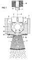
- FIG. 1 For example, as an embodiment, a valve in the form of an injector for fuel injection systems of mixture-compression spark-ignition internal combustion engines is partially shown.
- the fuel injection valve has a tubular valve seat carrier 1, which only schematically indicates a part of a valve housing and in which a longitudinal opening 3 is formed concentrically to a valve longitudinal axis 2.
- a longitudinal opening 3 In the longitudinal opening 3 is a z.
- the actuation of the fuel injection valve takes place in a known manner, for example electromagnetically.
- An actuation of the fuel injection valve with a piezoelectric or magnetostrictive actuator is also conceivable.
- electromagnetic circuit with a magnetic coil 10, an armature 11 and a core 12.
- the armature 11 is connected to the valve closing body 7 remote from the end of the valve needle 5 by, for example, a trained by a laser weld and aligned with the core 12.
- valve seat body 16 In the downstream end of the valve seat carrier 1 is a valve seat body 16, e.g. tightly assembled by welding.
- a perforated disc 23 is attached in the form of a multi-fan jet nozzle as atomizer.
- the connection of valve seat body 16 and perforated disc 23 is effected, for example, by a circumferential and dense laser-formed weld 26, which is e.g. is provided on the end face 17 or on the outer circumference of valve seat body 16 and perforated disc 23.
- the perforated disc 23 is engaged by a support plate 25.
- the support disk 25 is annular in order to receive a central dome-shaped or domed nozzle-like nozzle region 28 of the perforated disk 23 in an inner opening.
- an outlet opening 27 is provided, from which the fuel to be sprayed enters a flow cavity 24, which is formed by the curved or kalottator formation of the nozzle portion 28 of the perforated disc 23.
- the perforated disc 23 has, for example, in the region of the longitudinal axis of the valve 2 its greatest distance to the end face 17, while in the region of the weld 26, the perforated disc 23 abuts directly on the valve seat body 16 as a disc without curvature and is stabilized by the support plate 25.
- a plurality of very small spray openings 30 are provided, which are slit-shaped and extend parallel to the direction.
- the ejection openings 30 have a slot width of approximately 20 to 50 ⁇ m and a slot length of up to 150 ⁇ m, so that fuel sprays with extremely small fuel droplets with a Sauter Mean Diameter (SMD) of approximately 20 ⁇ m can be sprayed off. In this way, the HC emission of the internal combustion engine can be reduced significantly over known injection arrangements very effectively.
- Per perforated disc 23 are provided between two and sixty injection orifices 30, wherein a number of eight to forty injection orifices 30 brings optimal atomization results.
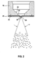
- FIG. 2 shows the downstream valve end of the fuel injection valve with the perforated disc 23 according to FIG. 1 in a 90 ° rotated side view. It is particularly clear that the central nozzle region 28 has an elongated elliptical shape. While the sprayed fuel spray in its longitudinal direction according to FIG. 1 For example, has an outer angle ⁇ with about 15 °, an outer angle ⁇ of the fuel spray in its transverse orientation according to FIG. 2 about 30 °.
- FIGS. 1 and 2 are the DE 10 2005 000 620 A1 taken and thus show a known multi-fan jet nozzle 23.
- the central nozzle portion 28 with the spray-discharge openings 30 is formed by embossing technology after the galvanic production of the disc.
- embossing tools for producing the nozzle portion 28 of the perforated disc 23 can be used, which are designed either annular or partially annular or elliptical or partially elliptical ( Figures 10 and 11 of DE 10 2005 000 620 A1 ).
- the curvature of the nozzle region 28 is shaped convexly in the direction of ejection.
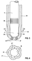
- FIG. 3 shows a valve end of a fuel injection valve according to the invention, in which a perforated disc 23 is completely dispensed with.
- the risk of crack formation is significantly reduced, since the slot-shaped spray-discharge openings 30 are introduced only after the forming of a valve sleeve 35, which is produced in particular by deep drawing, in this.
- the valve sleeve 35 includes compared with the FIG. 1 shown fuel injector, the components valve seat carrier 1 and valve seat body 16, wherein the valve seat surface 29 is mitausgeformt directly to the inner wall of the valve sleeve 35.
- the valve seat surface 29 is brought to the desired surface quality by means of ring honing, for example, and cured by means of laser.
- the valve sleeve 35 is designed as a multi-functional sleeve, since it carries both the valve seat 29 and the valve needle 5 during its axial movement on the inner wall leads.
- the valve needle 5 is at its downstream end, which acts as a valve closing body 7, without the known flats 8 (FIG. FIG. 1 ) to the Flowed past the fuel and instead continues to run hollow cylindrical.
- the valve sleeve 35 has over its downstream peripheral region on a plurality of web-shaped guide portions 36 which are radially inwardly displaced relative to the cylindrical course of the valve sleeve 35 and serve to guide the valve needle 5.
- the guide portions 36 are impressed in the valve sleeve 35 in an odd number, so for example in a number of three or five, as shown in the sectional view through the lower end of the valve sleeve 35 in FIG. 4 can be seen.
- On the outer circumference of the valve sleeve 35 results in the areas of the inwardly directed guide portions 36 recesses 41, since the material of the valve sleeve 35 at these locations pushed inward, moved, impressed o.ä. becomes.
- the valve needle 5, for example, as well as the valve sleeve 35 is made by deep drawing.
- the deep-drawn valve sleeve 35 is provided at the downstream end with a curvature 37, in which the particular slot-shaped spray openings 30 are introduced directly.
- the curvature 37 of the valve sleeve 35 is executed in the embodiment rotationally symmetrical dome-shaped, it may also be different from, for example, paraboloidal and elliptical of its base instead of circular.
- the ejection openings 30 are introduced after the deep-drawing process by means of the ultra-short-pulse laser technology.
- this laser technology makes it possible to produce injection-molding openings 30 of laser technology in sufficiently precise cross-sectional precision, which are used for spraying liquid lamellae in a multi-fan-shaped manner (see FIG. 1 ) is required.
- the slot-shaped spray-discharge openings 30 can be formed by means of laser technology perpendicular or obliquely to the surface normal of the curved valve sleeve 35. If both opposing slot longitudinal walls are introduced obliquely and directionally parallel to one another, the center axis of the exiting fan beam can be tilted relative to the surface normal of the curvature 37, regardless of the shape of the curvature 37.
- FIG. 5 an enlarged view of slotted spray openings 30 in a valve sleeve 35 is shown.
- the slot walls which extend in the slot longitudinal direction, not exactly aligned in direction parallel to each other limit the ejection openings 30, but apart in accordance with a fan-beam fanning angle to be set in the ejection direction diverge.
- the shown planar walls of the spray-discharge openings 30, these can also be convex / concave.
- the specific alignment of the laser for generating these walls can be done by deflecting the laser beam via tilting mirrors.
- the ejection openings 30 may have the cross-sectional shape of a rectangle, an ellipse or a lens or the like. to have. Two adjacent ejection openings 30 have e.g. a distance of about 40 to 60 microns.
- a likewise slot-shaped structure may be provided upstream of the valve seat 29, which serves as a filter 38 and e.g. is made by laser.
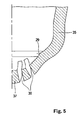
- FIG. 6 shows a valve end of a second fuel injection valve according to the invention, in which a perforated disc 23 is completely dispensed with.
- this embodiment differs in particular in the configuration of the valve needle 5 and the valve closing body 7 and in the embodiments of the ejection openings 30.
- the formed in particular by deep drawing valve sleeve 35 can also accommodate a known valve needle 5 with a spherical valve closing body 7.
- the combination of the high-precision valve sleeve 35 with a soft, highly elastic valve closing body 7, which adapts to the reshaped valve seat 29, leads to an improved and cost-effective sealing seat.
- the valve sleeve 35 in turn assumes the functions of a valve seat carrier and at the same time the valve seat body, wherein the valve seat surface 29 is mitausgeformt directly to the inner wall of the valve sleeve 35.
- the valve sleeve 35 is designed as a multi-functional sleeve, since it carries both the valve seat 29 and the valve needle 5 during its axial movement on the inner wall leads. In addition to the functions needle guide, fuel passage and leak tightness, the mixture preparation function is also integrated in the multifunction sleeve.
- the spray-discharge openings 30 are introduced directly in an eg curved bottom area.
- the spray-discharge openings 30 can also be circular or polygonal in addition to the slot-shaped configuration described above.
- the ejection openings 30 are introduced after the deep-drawing process by means of the ultra-short-pulse laser technology.
- the deep-drawing process is adapted so that in adjacent areas of areas with high precision requirement free-form surfaces are provided, which serve as a material overflow, whereby process fluctuations can be compensated.
- Another possibility for precision improvement is a local heating (laser, induction, resistance heating, friction, chemical reaction) of the valve sleeve 35 during the deep drawing process.
- the influence of residual stresses and texture are largely reduced by suitable material selection and targeted thermomechanical treatment. This can be done by a final annealing with subsequent Kalibrierarbeitsgang and / or the use of texture-free sheet or plate with rotationally symmetric texture.
- the application of an additional material a higher quality material on the material of the valve sleeve 35 local property improvements in terms of hardness, strength, hardenability, wear, elasticity, etc. can be achieved.
- valve seat surface 29 is brought to the desired surface quality, for example, in a finish machining by means of ring honing with bonded grain and hardened by means of laser.
- the grinding pin is designed so that the valve seat 29 and the needle guide area are processed in a single operation, so that a very good concentricity between the valve seat 29 and guide is achieved. Due to the precise pre-machining, economical reworking with the usual fine machining processes (grinding, lapping, embossing, EDM, ECM, laser processing, electron beam machining, etc.) is also possible at any time.
- the inner contour of the valve sleeve 35 is precisely machined by ⁇ -ECM by scanning the contour with the electrode to perform the ECM process.
- the valve seat surface 29, as in the FIGS. 3 to 5 shown protruding circumferentially bead-like inward only the bead tip serving the sealing seat must be accurately edited.
- a flexible clamping of the valve sleeve can be achieved that the inner contour of the valve sleeve 35 aligns with the grinding pin, so that caused by the deep drawing position deviations between inner and outer contour are compensated.
- the valve sleeve 35 is preferably aligned with the inner contour to allow a positionally correct mounting of the valve sleeve 35 on the fuel injection valve.
- the preparation of the injection openings 30 can be carried out by all common methods, such as drilling, punching, laser drilling, EDM, ECM, EDCM, ion beam, electron beam.
Landscapes
- Engineering & Computer Science (AREA)
- Chemical & Material Sciences (AREA)
- Combustion & Propulsion (AREA)
- Mechanical Engineering (AREA)
- General Engineering & Computer Science (AREA)
- Fuel-Injection Apparatus (AREA)
Applications Claiming Priority (3)
| Application Number | Priority Date | Filing Date | Title |
|---|---|---|---|
| DE102007062188 | 2007-12-21 | ||
| DE102008054840A DE102008054840A1 (de) | 2007-12-21 | 2008-12-17 | Brennstoffeinspritzventil |
| PCT/EP2008/067792 WO2009080671A1 (de) | 2007-12-21 | 2008-12-17 | Brennstoffeinspritzventil |
Publications (2)
| Publication Number | Publication Date |
|---|---|
| EP2238337A1 EP2238337A1 (de) | 2010-10-13 |
| EP2238337B1 true EP2238337B1 (de) | 2014-12-17 |
Family
ID=40459888
Family Applications (1)
| Application Number | Title | Priority Date | Filing Date |
|---|---|---|---|
| EP08865539.4A Not-in-force EP2238337B1 (de) | 2007-12-21 | 2008-12-17 | Brennstoffeinspritzventil |
Country Status (5)
| Country | Link |
|---|---|
| US (1) | US8430078B2 (enExample) |
| EP (1) | EP2238337B1 (enExample) |
| JP (1) | JP2011506849A (enExample) |
| DE (1) | DE102008054840A1 (enExample) |
| WO (1) | WO2009080671A1 (enExample) |
Families Citing this family (8)
| Publication number | Priority date | Publication date | Assignee | Title |
|---|---|---|---|---|
| US20130186367A1 (en) * | 2011-09-06 | 2013-07-25 | Mahle Koenig Kommanditgesellschaft Gmbh & Co Kg | Method, cylinder, and engine with central ignition spark position |
| JP6059915B2 (ja) * | 2012-08-27 | 2017-01-11 | 日立オートモティブシステムズ株式会社 | 燃料噴射弁 |
| DE102012221865A1 (de) | 2012-11-29 | 2014-06-05 | Robert Bosch Gmbh | Brennstoffeinspritzventil |
| DE102012222392A1 (de) | 2012-12-06 | 2014-06-12 | Robert Bosch Gmbh | Brennstoffeinspritzventil |
| US9470197B2 (en) | 2012-12-21 | 2016-10-18 | Caterpillar Inc. | Fuel injector having turbulence-reducing sac |
| CH709403A1 (de) * | 2014-03-25 | 2015-09-30 | Liebherr Machines Bulle Sa | Injektor und Verbrennungskraftmaschine mit entsprechendem Injektor. |
| EP2975255B1 (en) * | 2014-07-17 | 2019-06-12 | Continental Automotive GmbH | Nozzle body, the valve assembly and fluid injection valve |
| EP3156641A1 (en) * | 2015-10-14 | 2017-04-19 | Continental Automotive GmbH | Injector for injecting fluid |
Family Cites Families (34)
| Publication number | Priority date | Publication date | Assignee | Title |
|---|---|---|---|---|
| GB669110A (en) | 1948-06-04 | 1952-03-26 | Burmeister & Wains Mot Mask | Improvements in or relating to fuel injection nozzles for internal combustion engines |
| DE3934587C2 (de) * | 1989-10-17 | 1998-11-19 | Bosch Gmbh Robert | Verfahren zum Herstellen von mittels Laserstrahlung erzeugter, hochpräziser Durchgangsbohrungen in Werkstücken |
| JP3039714B2 (ja) * | 1991-12-05 | 2000-05-08 | 株式会社デンソー | 電磁式燃料噴射弁 |
| JP3133588B2 (ja) | 1993-11-26 | 2001-02-13 | 三洋電機株式会社 | 電子部品自動装着装置及び電子部品の装着方法 |
| DE4426006A1 (de) * | 1994-07-22 | 1996-01-25 | Bosch Gmbh Robert | Ventilnadel für ein elektromagnetisch betätigbares Ventil und Verfahren zur Herstellung |
| JPH0966381A (ja) * | 1995-09-01 | 1997-03-11 | Zexel Corp | 孔明け加工方法、孔明け加工装置および燃料噴射ノズルのノズルボディ |
| DE19546428A1 (de) | 1995-12-13 | 1997-06-19 | Bosch Gmbh Robert | Einspritzventil |
| DE19631066A1 (de) | 1996-08-01 | 1998-02-05 | Bosch Gmbh Robert | Brennstoffeinspritzventil |
| DE19636396B4 (de) | 1996-09-07 | 2005-03-10 | Bosch Gmbh Robert | Brennstoffeinspritzventil |
| DE19653832A1 (de) | 1996-12-21 | 1998-06-25 | Bosch Gmbh Robert | Ventil mit kombiniertem Ventilsitzkörper und Spritzlochscheibe |
| DE19712922B4 (de) * | 1997-03-27 | 2005-08-11 | Robert Bosch Gmbh | Brennstoffeinspritzventil |
| DE19726991A1 (de) | 1997-06-25 | 1999-01-07 | Bosch Gmbh Robert | Ventil und Verfahren zur Herstellung eines Ventilsitzes für ein Ventil |
| JP3329239B2 (ja) * | 1997-09-05 | 2002-09-30 | トヨタ自動車株式会社 | 燃料噴射弁 |
| JPH11117831A (ja) | 1997-10-17 | 1999-04-27 | Toyota Motor Corp | 内燃機関用燃料噴射弁 |
| JP3323429B2 (ja) | 1997-11-19 | 2002-09-09 | トヨタ自動車株式会社 | 内燃機関用燃料噴射弁 |
| DE19858345A1 (de) * | 1998-01-06 | 1999-07-08 | Mitsubishi Motors Corp | Brennstoffeinspritzdüse |
| JP3385989B2 (ja) * | 1999-01-13 | 2003-03-10 | トヨタ自動車株式会社 | 燃料噴射弁 |
| DE19927899A1 (de) * | 1999-06-18 | 2000-12-21 | Bosch Gmbh Robert | Brennstoffeinspritzventil |
| JP2001065431A (ja) * | 1999-08-27 | 2001-03-16 | Toyota Motor Corp | 内燃機関用燃料噴射弁 |
| DE10034444A1 (de) | 2000-07-15 | 2002-01-24 | Bosch Gmbh Robert | Brennstoffeinspritzventil |
| JP2002130080A (ja) * | 2000-10-26 | 2002-05-09 | Aisan Ind Co Ltd | インジェクタ |
| DE10108945A1 (de) * | 2001-02-24 | 2002-09-05 | Bosch Gmbh Robert | Brennstoffeinspritzventil |
| JP4110974B2 (ja) | 2002-05-10 | 2008-07-02 | トヨタ自動車株式会社 | 筒内噴射式火花点火内燃機関 |
| JP4007202B2 (ja) * | 2003-01-23 | 2007-11-14 | 株式会社デンソー | 軸部材の摺動構造およびインジェクタ |
| FR2851792B1 (fr) * | 2003-02-28 | 2007-02-09 | Magneti Marelli Motopropulsion | Injecteur de carburant pour moteur a combustion interne |
| US7334746B2 (en) * | 2004-03-08 | 2008-02-26 | Continental Automotive Systems Us, Inc. | Seat-lower guide combination |
| DE102005000620A1 (de) | 2005-01-03 | 2006-07-13 | Robert Bosch Gmbh | Multi-Fächerstrahl-Düse und Brennstoffeinspritzventil mit Multi-Fächerstrahl-Düse |
| JP2006258035A (ja) * | 2005-03-18 | 2006-09-28 | Denso Corp | 燃料噴射弁 |
| JP4619989B2 (ja) * | 2005-07-04 | 2011-01-26 | 株式会社デンソー | 燃料噴射弁 |
| JP2007120471A (ja) * | 2005-10-31 | 2007-05-17 | Toyota Tsusho Corp | 燃料噴射弁用ハウジングの製造方法及び燃料噴射弁用ハウジング |
| DE102005052252A1 (de) * | 2005-11-02 | 2007-05-03 | Robert Bosch Gmbh | Brennstoffeinspritzventil |
| DE102005061424A1 (de) | 2005-12-22 | 2007-07-05 | Robert Bosch Gmbh | Brennstoffeinspritzventil |
| JP2007313525A (ja) * | 2006-05-24 | 2007-12-06 | Toyota Motor Corp | 孔加工方法及び孔加工装置 |
| JP5157023B1 (ja) | 2011-08-08 | 2013-03-06 | 三井金属アクト株式会社 | ロック装置 |
-
2008
- 2008-12-17 WO PCT/EP2008/067792 patent/WO2009080671A1/de not_active Ceased
- 2008-12-17 EP EP08865539.4A patent/EP2238337B1/de not_active Not-in-force
- 2008-12-17 DE DE102008054840A patent/DE102008054840A1/de not_active Withdrawn
- 2008-12-17 US US12/809,689 patent/US8430078B2/en not_active Expired - Fee Related
- 2008-12-17 JP JP2010538716A patent/JP2011506849A/ja active Pending
Also Published As
| Publication number | Publication date |
|---|---|
| WO2009080671A1 (de) | 2009-07-02 |
| EP2238337A1 (de) | 2010-10-13 |
| JP2011506849A (ja) | 2011-03-03 |
| US8430078B2 (en) | 2013-04-30 |
| US20100269788A1 (en) | 2010-10-28 |
| DE102008054840A1 (de) | 2009-06-25 |
Similar Documents
| Publication | Publication Date | Title |
|---|---|---|
| EP2238337B1 (de) | Brennstoffeinspritzventil | |
| EP0937202B1 (de) | Brennstoffeinspritzventil | |
| EP1355061B1 (de) | Einspritzventil, insbesondere Brennstoffeinspritzventil | |
| DE19703200A1 (de) | Brennstoffeinspritzventil | |
| DE19937961A1 (de) | Brennstoffeinspritzventil und Verfahren zur Herstellung von Austrittsöffnungen an Ventilen | |
| EP1339975A1 (de) | Brennstoffeinspritzventil | |
| WO1999032259A1 (de) | Verfahren zur herstellung eines ventilsitzkörpers für ein brennstoffeinspritzventil und brennstoffeinspritzventil | |
| DE19636396A1 (de) | Brennstoffeinspritzventil | |
| EP0939858B1 (de) | Lochscheibe bzw. zerstäuberscheibe und einspritzventil mit einer lochscheibe bzw. zerstäuberscheibe | |
| EP1402175A1 (de) | Brennstoffeinspritzventil | |
| EP1399669A1 (de) | Brennstoffeinspritzventil | |
| EP1409867B1 (de) | Brennstoffeinspritzventil | |
| EP1474604A1 (de) | Brennstoffeinspritzventil | |
| EP1392969B1 (de) | Brennstoffeinspritzventil | |
| DE10050751A1 (de) | Brennstoffeinspritzventil | |
| EP1613857B1 (de) | Verfahren zur herstellung und befestigung einer lochscheibe | |
| DE102012221865A1 (de) | Brennstoffeinspritzventil | |
| EP2072805B1 (de) | Brennstoffeinspritzventil | |
| DE102012222392A1 (de) | Brennstoffeinspritzventil | |
| WO1992003651A1 (de) | Brennstoffeinspritzventil | |
| EP1105641A1 (de) | Brennstoffeinspritzventil | |
| DE102007062183A1 (de) | Brennstoffeinspritzventil | |
| DE19831845A1 (de) | Lochscheibe bzw. Zerstäuberscheibe und Einspritzventil mit einer Lochscheibe bzw. Zerstäuberscheibe | |
| WO2004101986A9 (de) | Brennstoffeinspritzventil | |
| DE102018221833A1 (de) | Ventil zum Zumessen eines Fluids, insbesondere Brennstoffeinspritzventil |
Legal Events
| Date | Code | Title | Description |
|---|---|---|---|
| PUAI | Public reference made under article 153(3) epc to a published international application that has entered the european phase |
Free format text: ORIGINAL CODE: 0009012 |
|
| 17P | Request for examination filed |
Effective date: 20100721 |
|
| AK | Designated contracting states |
Kind code of ref document: A1 Designated state(s): AT BE BG CH CY CZ DE DK EE ES FI FR GB GR HR HU IE IS IT LI LT LU LV MC MT NL NO PL PT RO SE SI SK TR |
|
| AX | Request for extension of the european patent |
Extension state: AL BA MK RS |
|
| DAX | Request for extension of the european patent (deleted) | ||
| 17Q | First examination report despatched |
Effective date: 20111031 |
|
| GRAP | Despatch of communication of intention to grant a patent |
Free format text: ORIGINAL CODE: EPIDOSNIGR1 |
|
| INTG | Intention to grant announced |
Effective date: 20140925 |
|
| GRAS | Grant fee paid |
Free format text: ORIGINAL CODE: EPIDOSNIGR3 |
|
| GRAA | (expected) grant |
Free format text: ORIGINAL CODE: 0009210 |
|
| AK | Designated contracting states |
Kind code of ref document: B1 Designated state(s): AT BE BG CH CY CZ DE DK EE ES FI FR GB GR HR HU IE IS IT LI LT LU LV MC MT NL NO PL PT RO SE SI SK TR |
|
| REG | Reference to a national code |
Ref country code: GB Ref legal event code: FG4D Free format text: NOT ENGLISH |
|
| REG | Reference to a national code |
Ref country code: CH Ref legal event code: EP |
|
| REG | Reference to a national code |
Ref country code: IE Ref legal event code: FG4D Free format text: LANGUAGE OF EP DOCUMENT: GERMAN |
|
| REG | Reference to a national code |
Ref country code: AT Ref legal event code: REF Ref document number: 702133 Country of ref document: AT Kind code of ref document: T Effective date: 20150115 |
|
| REG | Reference to a national code |
Ref country code: DE Ref legal event code: R096 Ref document number: 502008012520 Country of ref document: DE Effective date: 20150129 |
|
| PG25 | Lapsed in a contracting state [announced via postgrant information from national office to epo] |
Ref country code: NO Free format text: LAPSE BECAUSE OF FAILURE TO SUBMIT A TRANSLATION OF THE DESCRIPTION OR TO PAY THE FEE WITHIN THE PRESCRIBED TIME-LIMIT Effective date: 20150317 Ref country code: FI Free format text: LAPSE BECAUSE OF FAILURE TO SUBMIT A TRANSLATION OF THE DESCRIPTION OR TO PAY THE FEE WITHIN THE PRESCRIBED TIME-LIMIT Effective date: 20141217 Ref country code: LT Free format text: LAPSE BECAUSE OF FAILURE TO SUBMIT A TRANSLATION OF THE DESCRIPTION OR TO PAY THE FEE WITHIN THE PRESCRIBED TIME-LIMIT Effective date: 20141217 |
|
| REG | Reference to a national code |
Ref country code: LT Ref legal event code: MG4D |
|
| PG25 | Lapsed in a contracting state [announced via postgrant information from national office to epo] |
Ref country code: LV Free format text: LAPSE BECAUSE OF FAILURE TO SUBMIT A TRANSLATION OF THE DESCRIPTION OR TO PAY THE FEE WITHIN THE PRESCRIBED TIME-LIMIT Effective date: 20141217 Ref country code: HR Free format text: LAPSE BECAUSE OF FAILURE TO SUBMIT A TRANSLATION OF THE DESCRIPTION OR TO PAY THE FEE WITHIN THE PRESCRIBED TIME-LIMIT Effective date: 20141217 Ref country code: SE Free format text: LAPSE BECAUSE OF FAILURE TO SUBMIT A TRANSLATION OF THE DESCRIPTION OR TO PAY THE FEE WITHIN THE PRESCRIBED TIME-LIMIT Effective date: 20141217 Ref country code: GR Free format text: LAPSE BECAUSE OF FAILURE TO SUBMIT A TRANSLATION OF THE DESCRIPTION OR TO PAY THE FEE WITHIN THE PRESCRIBED TIME-LIMIT Effective date: 20150318 |
|
| PG25 | Lapsed in a contracting state [announced via postgrant information from national office to epo] |
Ref country code: NL Free format text: LAPSE BECAUSE OF FAILURE TO SUBMIT A TRANSLATION OF THE DESCRIPTION OR TO PAY THE FEE WITHIN THE PRESCRIBED TIME-LIMIT Effective date: 20141217 Ref country code: BE Free format text: LAPSE BECAUSE OF NON-PAYMENT OF DUE FEES Effective date: 20141231 |
|
| PG25 | Lapsed in a contracting state [announced via postgrant information from national office to epo] |
Ref country code: ES Free format text: LAPSE BECAUSE OF FAILURE TO SUBMIT A TRANSLATION OF THE DESCRIPTION OR TO PAY THE FEE WITHIN THE PRESCRIBED TIME-LIMIT Effective date: 20141217 Ref country code: SK Free format text: LAPSE BECAUSE OF FAILURE TO SUBMIT A TRANSLATION OF THE DESCRIPTION OR TO PAY THE FEE WITHIN THE PRESCRIBED TIME-LIMIT Effective date: 20141217 Ref country code: CZ Free format text: LAPSE BECAUSE OF FAILURE TO SUBMIT A TRANSLATION OF THE DESCRIPTION OR TO PAY THE FEE WITHIN THE PRESCRIBED TIME-LIMIT Effective date: 20141217 Ref country code: EE Free format text: LAPSE BECAUSE OF FAILURE TO SUBMIT A TRANSLATION OF THE DESCRIPTION OR TO PAY THE FEE WITHIN THE PRESCRIBED TIME-LIMIT Effective date: 20141217 Ref country code: RO Free format text: LAPSE BECAUSE OF FAILURE TO SUBMIT A TRANSLATION OF THE DESCRIPTION OR TO PAY THE FEE WITHIN THE PRESCRIBED TIME-LIMIT Effective date: 20141217 |
|
| REG | Reference to a national code |
Ref country code: CH Ref legal event code: PL |
|
| PG25 | Lapsed in a contracting state [announced via postgrant information from national office to epo] |
Ref country code: IS Free format text: LAPSE BECAUSE OF FAILURE TO SUBMIT A TRANSLATION OF THE DESCRIPTION OR TO PAY THE FEE WITHIN THE PRESCRIBED TIME-LIMIT Effective date: 20150417 Ref country code: PL Free format text: LAPSE BECAUSE OF FAILURE TO SUBMIT A TRANSLATION OF THE DESCRIPTION OR TO PAY THE FEE WITHIN THE PRESCRIBED TIME-LIMIT Effective date: 20141217 |
|
| REG | Reference to a national code |
Ref country code: DE Ref legal event code: R097 Ref document number: 502008012520 Country of ref document: DE |
|
| REG | Reference to a national code |
Ref country code: IE Ref legal event code: MM4A |
|
| PLBE | No opposition filed within time limit |
Free format text: ORIGINAL CODE: 0009261 |
|
| STAA | Information on the status of an ep patent application or granted ep patent |
Free format text: STATUS: NO OPPOSITION FILED WITHIN TIME LIMIT |
|
| PG25 | Lapsed in a contracting state [announced via postgrant information from national office to epo] |
Ref country code: CH Free format text: LAPSE BECAUSE OF NON-PAYMENT OF DUE FEES Effective date: 20141231 Ref country code: DK Free format text: LAPSE BECAUSE OF FAILURE TO SUBMIT A TRANSLATION OF THE DESCRIPTION OR TO PAY THE FEE WITHIN THE PRESCRIBED TIME-LIMIT Effective date: 20141217 Ref country code: LI Free format text: LAPSE BECAUSE OF NON-PAYMENT OF DUE FEES Effective date: 20141231 Ref country code: IE Free format text: LAPSE BECAUSE OF NON-PAYMENT OF DUE FEES Effective date: 20141217 |
|
| REG | Reference to a national code |
Ref country code: FR Ref legal event code: ST Effective date: 20151016 |
|
| 26N | No opposition filed |
Effective date: 20150918 |
|
| GBPC | Gb: european patent ceased through non-payment of renewal fee |
Effective date: 20150317 |
|
| PG25 | Lapsed in a contracting state [announced via postgrant information from national office to epo] |
Ref country code: IT Free format text: LAPSE BECAUSE OF NON-PAYMENT OF DUE FEES Effective date: 20141217 |
|
| PG25 | Lapsed in a contracting state [announced via postgrant information from national office to epo] |
Ref country code: GB Free format text: LAPSE BECAUSE OF NON-PAYMENT OF DUE FEES Effective date: 20150317 |
|
| REG | Reference to a national code |
Ref country code: AT Ref legal event code: MM01 Ref document number: 702133 Country of ref document: AT Kind code of ref document: T Effective date: 20141217 |
|
| PG25 | Lapsed in a contracting state [announced via postgrant information from national office to epo] |
Ref country code: FR Free format text: LAPSE BECAUSE OF NON-PAYMENT OF DUE FEES Effective date: 20150217 Ref country code: SI Free format text: LAPSE BECAUSE OF FAILURE TO SUBMIT A TRANSLATION OF THE DESCRIPTION OR TO PAY THE FEE WITHIN THE PRESCRIBED TIME-LIMIT Effective date: 20141217 |
|
| PG25 | Lapsed in a contracting state [announced via postgrant information from national office to epo] |
Ref country code: BG Free format text: LAPSE BECAUSE OF FAILURE TO SUBMIT A TRANSLATION OF THE DESCRIPTION OR TO PAY THE FEE WITHIN THE PRESCRIBED TIME-LIMIT Effective date: 20141217 Ref country code: AT Free format text: LAPSE BECAUSE OF NON-PAYMENT OF DUE FEES Effective date: 20141217 |
|
| PG25 | Lapsed in a contracting state [announced via postgrant information from national office to epo] |
Ref country code: PT Free format text: LAPSE BECAUSE OF FAILURE TO SUBMIT A TRANSLATION OF THE DESCRIPTION OR TO PAY THE FEE WITHIN THE PRESCRIBED TIME-LIMIT Effective date: 20141217 Ref country code: CY Free format text: LAPSE BECAUSE OF FAILURE TO SUBMIT A TRANSLATION OF THE DESCRIPTION OR TO PAY THE FEE WITHIN THE PRESCRIBED TIME-LIMIT Effective date: 20141217 Ref country code: MC Free format text: LAPSE BECAUSE OF NON-PAYMENT OF DUE FEES Effective date: 20141217 |
|
| PG25 | Lapsed in a contracting state [announced via postgrant information from national office to epo] |
Ref country code: HU Free format text: LAPSE BECAUSE OF FAILURE TO SUBMIT A TRANSLATION OF THE DESCRIPTION OR TO PAY THE FEE WITHIN THE PRESCRIBED TIME-LIMIT; INVALID AB INITIO Effective date: 20081217 Ref country code: TR Free format text: LAPSE BECAUSE OF FAILURE TO SUBMIT A TRANSLATION OF THE DESCRIPTION OR TO PAY THE FEE WITHIN THE PRESCRIBED TIME-LIMIT Effective date: 20141217 Ref country code: LU Free format text: LAPSE BECAUSE OF NON-PAYMENT OF DUE FEES Effective date: 20141217 Ref country code: MT Free format text: LAPSE BECAUSE OF FAILURE TO SUBMIT A TRANSLATION OF THE DESCRIPTION OR TO PAY THE FEE WITHIN THE PRESCRIBED TIME-LIMIT Effective date: 20141217 |
|
| PG25 | Lapsed in a contracting state [announced via postgrant information from national office to epo] |
Ref country code: IT Free format text: LAPSE BECAUSE OF NON-PAYMENT OF DUE FEES Effective date: 20141217 |
|
| PGRI | Patent reinstated in contracting state [announced from national office to epo] |
Ref country code: IT Effective date: 20170616 |
|
| PGFP | Annual fee paid to national office [announced via postgrant information from national office to epo] |
Ref country code: IT Payment date: 20221230 Year of fee payment: 15 Ref country code: DE Payment date: 20230223 Year of fee payment: 15 |
|
| P01 | Opt-out of the competence of the unified patent court (upc) registered |
Effective date: 20230509 |
|
| REG | Reference to a national code |
Ref country code: DE Ref legal event code: R119 Ref document number: 502008012520 Country of ref document: DE |
|
| PG25 | Lapsed in a contracting state [announced via postgrant information from national office to epo] |
Ref country code: DE Free format text: LAPSE BECAUSE OF NON-PAYMENT OF DUE FEES Effective date: 20240702 |
|
| PG25 | Lapsed in a contracting state [announced via postgrant information from national office to epo] |
Ref country code: DE Free format text: LAPSE BECAUSE OF NON-PAYMENT OF DUE FEES Effective date: 20240702 |
|
| PG25 | Lapsed in a contracting state [announced via postgrant information from national office to epo] |
Ref country code: IT Free format text: LAPSE BECAUSE OF NON-PAYMENT OF DUE FEES Effective date: 20231217 |