EP2237303A1 - Unité de fusible pour un panneau d'interrupteurs d'une installation de commutation électrique, notamment d'une installation de commutation de moyenne tension à air isolé - Google Patents
Unité de fusible pour un panneau d'interrupteurs d'une installation de commutation électrique, notamment d'une installation de commutation de moyenne tension à air isolé Download PDFInfo
- Publication number
- EP2237303A1 EP2237303A1 EP10001704A EP10001704A EP2237303A1 EP 2237303 A1 EP2237303 A1 EP 2237303A1 EP 10001704 A EP10001704 A EP 10001704A EP 10001704 A EP10001704 A EP 10001704A EP 2237303 A1 EP2237303 A1 EP 2237303A1
- Authority
- EP
- European Patent Office
- Prior art keywords
- fuse
- carriage
- state
- unit
- carrier
- Prior art date
- Legal status (The legal status is an assumption and is not a legal conclusion. Google has not performed a legal analysis and makes no representation as to the accuracy of the status listed.)
- Granted
Links
- 230000007704 transition Effects 0.000 claims description 14
- 230000001960 triggered effect Effects 0.000 description 8
- 238000010304 firing Methods 0.000 description 2
- 239000011810 insulating material Substances 0.000 description 2
- 241001136792 Alle Species 0.000 description 1
- 230000000694 effects Effects 0.000 description 1
- 238000009472 formulation Methods 0.000 description 1
- 239000000203 mixture Substances 0.000 description 1
Images


Classifications
-
- H—ELECTRICITY
- H01—ELECTRIC ELEMENTS
- H01H—ELECTRIC SWITCHES; RELAYS; SELECTORS; EMERGENCY PROTECTIVE DEVICES
- H01H85/00—Protective devices in which the current flows through a part of fusible material and this current is interrupted by displacement of the fusible material when this current becomes excessive
- H01H85/54—Protective devices wherein the fuse is carried, held, or retained by an intermediate or auxiliary part removable from the base, or used as sectionalisers
- H01H85/547—Protective devices wherein the fuse is carried, held, or retained by an intermediate or auxiliary part removable from the base, or used as sectionalisers with sliding fuse carrier
-
- H—ELECTRICITY
- H02—GENERATION; CONVERSION OR DISTRIBUTION OF ELECTRIC POWER
- H02B—BOARDS, SUBSTATIONS OR SWITCHING ARRANGEMENTS FOR THE SUPPLY OR DISTRIBUTION OF ELECTRIC POWER
- H02B11/00—Switchgear having carriage withdrawable for isolation
- H02B11/26—Arrangements of fuses, resistors, voltage arresters or the like
Definitions
- the invention relates to a fuse unit for a control panel of an electrical switchgear, in particular an air-insulated medium voltage switchgear.
- the object of the invention is to provide a fuse unit for a control panel of an electrical switchgear, can be exchanged at the triggered fuses without much effort.
- the invention achieves this object by a securing unit according to claim 1.
- the fuse is arranged on a carriage and the switching field has a carrier.
- the carriage and the carrier are adapted to each other so that the carriage can be placed on the carrier.
- the fuse can be transferred from a connected state to a non-connected state by movement of the carriage.
- the fuse is therefore not permanently installed in the panel. Instead, the fuse can be transferred together with the carrier in the non-connected state, in which the entire assembly can be removed from the panel. When removing the possibly still hot fuse itself must not be touched. Furthermore, the backup can be contacted without much effort on the carriage. This can be designed such that the replacement of a fuse does not require a tool. This makes it possible to replace a triggered fuse immediately, quickly, without tools and otherwise with very little effort.
- the carriage is displaceable on the carrier. This allows a tripped fuse on the carriage along the carrier to be pulled out of the panel. The operator does not have to enter the interior of the panel in any way. The same applies to the transfer of the carriage with the replaced fuse from the non-connected state to the connected state. The replacement of a fuse is safer to carry out so far.
- the fuse unit is provided with at least two fuses, which are connectable to respective associated electrical components of the panel.
- Each of the fuses may have a connected state in which the respective fuse is connected to the respective associated electrical components of the panel.
- Each of the fuses may have a latched condition in which the respective fuse is latched within the panel.
- a ready state is present in which all fuses of the panel are in their locked state.
- the Transition from a non-connected state to the connected state can be achieved by an operator moving the fuse along with the carriage along the carrier.
- the transition from the connected state to the locked state can be achieved, for example, by an operator actuating a corresponding slide.
- a tripping of one of the fuses leads to a transition to the connected state. This ensures that the ready state is displayed only when all fuses are intact, connected, and locked. Furthermore, it is achieved that the triggered fuse can now be replaced in the connected and thus non-locked state.
- one of the electrical components of the switching field for example a circuit breaker, can be controlled.
- the power switch may be controlled to its open state whenever the ready state is not present.
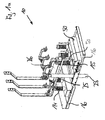
- FIGS. 1a . 1b show a schematic perspective view and a schematic side view of an embodiment of a fuse unit according to the invention with built-in fuse
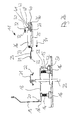
- FIGS. 2a . 2 B show a schematic perspective view and a schematic side view of the fuse unit of FIGS. 1a . 1b with fuse pulled out.
- An electrical switchgear in particular an air-insulated medium-voltage switchgear, consists of a plurality of switching fields.
- the panels are electrically connected to each other via busbars.
- different electrical components are housed, such as circuit breakers, disconnector / earthing switch and the like.
- branches from the busbars to electrical consumers are realized via these electrical components.
- a fuse unit 10 is accommodated in the cable connection space. It is understood that the fuse unit 10 may be housed in another area of the panel. In the present embodiment, the Assured fuse unit 10 in electrical terms associated with the downgoing electrical cables. It is understood that the fuse unit 10 may be associated with other electrical cables or busbars of the panel.
- the fuse unit 10 is formed in the present embodiment, three-phase. This goes in particular from the perspective views of FIGS. 1a . 2a out. It is understood that the fuse unit 10 may also have a different number of phases.
- the fuse unit 10 is constructed from three similarly constructed fuse components 11. Each fuse component 11 belongs to a phase of the fuse unit 10. Such a single fuse component 11 is shown in the side views of Figures 1b . 2 B shown. Hereinafter, one of these backup components 11 will be described.
- a carrier 13 made of insulating material is mounted inside the cable connection space on two insulating supports 14, 15.
- the supporters 14, 15 are in turn attached to the bottom of the cable connection space on housing parts 16 of the panel.
- the carrier 13 is rectilinear and aligned approximately horizontally within the panel. By the carrier 13, a longitudinal direction is set within the cable connection space.
- a first bus bar 18 is fixedly secured to the support 14 within the cable connection space, on the one hand has an upwardly outgoing free end 19, and on the other hand, a free end 20 is attached, which is a first power connection.
- the upwardly outgoing free end 19 is connected to the power switch associated with the respective phase.
- a second bus bar 21 is fixedly disposed within the cable connection space having a free end 22 which constitutes a second power connection.
- the attachment of the second busbar 21 within the panel is not shown in detail in the figures.
- the second bus bar 21 is connected to an electric cable 23 which goes down and exits the cable compartment through the bottom of the cable compartment.
- the two bus bars 18, 21 with the two free ends 20, 22 are arranged in a common, approximately vertical and parallel to the longitudinal direction aligned plane.
- the two free ends 20, 22 are aligned approximately horizontally and point in the same direction. From the side views of Figures 1b . 2 B It can be seen that the two free ends 20, 22 are arranged offset to one another in the longitudinal direction of the carrier 13.
- the carriage 25 is rectilinear and has a length which corresponds approximately to the length of the carrier 13.
- the carriage 25 and the carrier 13 are adapted to each other so that the carriage 25 can be placed on the stationary support 13 and the same can be moved in the longitudinal direction. If the carriage 25 is located on the carrier 13, the carriage 25 is approximately horizontal and aligned in the longitudinal direction.
- a fuse 26 is attached, which extends over a large part of the length of the carriage 25th extends.
- the attachment of the fuse 26 is achieved in that cup-shaped holders 27 are provided on the carriage 25, in the cylindrical ends of the fuse 26 can be clamped without the aid of tools.
- the brackets 27 are electrically conductive, so that via the brackets 27 an electrical connection to the fuse 26 can be produced. It is understood that other types of fastening can be provided in which the fuse 26 is screwed, for example, with the carriage 25.
- a third and a fourth bus bar 29, 30 are fixed, which are electrically connected to the respective associated holder 27.
- the third and fourth bus bars 29, 30 each have a free end 31, 32 which are both aligned in the same direction.
- the free end 31 of the third bus bar 29 is for connection to the first power terminal and the free end 32 of the fourth bus bar 30 is for connection to the second power terminal.
- the third and fourth busbars 29, 30 are arranged with the associated free ends 31, 32 in the already mentioned, approximately vertically oriented plane, in which also the first and the second busbar 18, 21 are present.
- the direction of the free ends 31, 32 of the third and fourth busbar 29, 30 is opposite to the direction of the free ends 20, 22 of the first and second busbar 18, 21 aligned.
- At the free ends 31, 32 of the third and fourth busbar 29, 30 each have a U-shaped opening 33 is attached, which is adapted to the free ends 20, 22 of the first and second busbar 18, 21.
- first and second bus bars 18, 21 with the associated free ends 20, 22 are arranged fixedly within the cable connection space, while the third and fourth bus bars 29, 30 are secured on the slide 25 with the associated free ends 31, 32.
- the carriage 25 is designed to be displaceable along the carrier 13.
- the four bus bars 18, 21, 29, 30 and in particular the associated free ends 20, 22, 31, 32 are aligned with one another such that the following two states can arise.
- a first state in the FIGS. 1a . 1b is shown, and referred to as the connected state, the free ends 20, 22 of the first and second bus bars 18, 21 are inserted into the U-shaped openings 33 of the third and fourth bus bars 29, 30. There is thus an electrical connection between the first busbar 18 and the third busbar 29 via the first power connection and between the second busbar 21 and the fourth busbar 30 via the second power connection.
- This is equivalent to having an electrical connection from the power switch connected to the first bus bar 18 via the fuse 26 to the second bus bar 21 and thus to the cable 23.
- the connected state can be achieved by manually sliding the carriage 25 along the carrier 13 in the longitudinal direction of the first busbar 18, until the illustrated electrical connection is established.
- the shift direction in the connected state is in the FIG. 2b indicated by the arrow 34.
- the free ends 20, 22 are opposite to the direction of the arrow 34 and the free ends 31, 32 with the openings 33 are aligned in the direction of the arrow 34, so that upon movement of the carriage 25 in the direction of the arrow 34, the free ends 20, 22 automatically engage in the openings 33 of the free ends 31, 32.
- the carriage 25 In the connected state, the carriage 25 is substantially completely on the carrier 13.
- the non-connected state can be achieved in that the carriage 25 is manually moved or pulled in the opposite direction to the arrow 34 along the carrier 13. In the transition from the connected to the non-connected state, the carriage 25 leaves more and more the carrier 13 and can be lifted manually from the carrier 13.
- an exchange of the fuse 26 in the absence of replacement fuse component can be achieved in that the fuse component 11 is taken out with the fuse to be replaced 26 from the panel. Then the fuse 26 can be replaced by a similar replacement fuse. If the illustrated brackets 27 are present, then this replacement of the fuse 26 can be performed without tools. Otherwise, the fuse 26 must be solved with the necessary tools, the replacement fuse used and fixed again. Thereafter, the carriage 25 can be placed with the replacement fuse on the carrier 13 and pushed in the connected state.
- the securing component 11 is provided with a locking mechanism 40 which is mounted on the carriage 25.
- the carriage 25 is in the connected state and the carriage 25 is arranged in a position provided for locking on the carrier 13, it is by a manual operation of a slider 41 in the direction of in the FIG. 1b indicated arrow 42 reaches a locking of the carriage 25 with the carrier 13.
- the operation of the slider 41 thereby causes a (not shown) pin within of the actuating mechanism is moved in the direction of the arrow 42, and that during this movement, the pin in a provided for locking (not shown) opening in the carrier 13 is immersed. In the locked state, a locking of the pin takes place.
- a shutter 44 is moved in the longitudinal direction according to the arrow 45 on the fuse 26 by the slider 41, in such a way that the trigger 44 bears against the fuse 26 or has a small distance from the fuse 26.
- This trigger 41 then locks in the position described.
- the state in which the carriage 25 and the carrier 13 are locked and the trigger 44 associated with the fuse 26 is referred to as a locked state. In this locked state and the fuse 26 is locked on the carriage 25 within the panel.
- the fuse 26 is triggered in operation, for example, by an excessive current, this has the consequence that a (not shown) striker from the fuse 26 thereof in the longitudinal direction of the trigger 44 moves.
- the current flow is interrupted.
- the firing pin of the trigger 44 is moved in the opposite direction to the arrow 45, which has the consequence that the locking of the carriage 25 is canceled with the carrier 13. This is accomplished by terminating the illustrated detent and pulling the aforementioned pin out of the aforementioned opening of the carrier 13 by a spring (not shown).
- the locked state can be canceled by a bolt 47 manually in the direction of the arrow 48 pulled out and thus the trigger 44 is moved independently of the firing pin of the fuse 26 in the opposite direction to the arrow 45.
- the fuse unit 10 has three phases, the fuse component 11 explained above being present in the cable connection space for each of the phases.
- the three securing components 11 are arranged approximately parallel to each other, as can be seen from the perspective views of FIGS. 1a . 2a evident.
- the fuse unit 10 has a display mechanism 50, which is coupled to all three fuse components 11, and which is fixedly arranged at the bottom of the cable connection space.
- the indicator mechanism 50 has a shaft (not shown) extending transversely to the longitudinal direction and provided below all three securing components 11.
- the shaft is associated with at least one spring (not shown) that attempts to move the shaft to a rotational position that corresponds to a ready state.
- Each of the three securing components 11 is provided with a rod 52, which can assume a raised and a lowered state.
- a spring (not shown) attempts to move rod 52 in the direction of arrow 53 to the raised position.
- Each of the three rods 52 acts on the shaft such that no rotational movement of the shaft is possible as long as one of the three rods 52 is in its raised state.
- the shaft with three (not shown) levers provided with the three rods 52 of the three securing components 11 cooperate such that each of the rods 52 blocks movement of the associated lever, as long as the respective rod 52 is in its raised state.
- a rotational movement of the shaft in the ready state is therefore only possible if all three rods 52 of the three fuse components 11 are not in their raised state, so if all three rods are in their lowered state.
- the associated rod 52 is coupled within the associated locking mechanism 41 with the associated associated slider 41 there. If this associated slide 41 is not actuated, then the associated rod 52 is in its raised state. However, if the slider 41 is manually operated in the direction of the arrow 42 and thus takes place a transition to the locked state, the associated rod 52 goes into its lowered state. Together with the slider 41, the rod 52 is locked in the lowered state. When a release of the fuse 26, as well as in a release by means of the bolt 47, as explained, the detent stops, so that the rod 52 passes again by means of said spring in its raised state.
- the shaft may be associated within the display mechanism 50 with an electrical switch (not shown) that generates an ON signal when the shaft is in the ready state and otherwise provides an OFF signal.
- the associated circuit breaker can be switched to its closed or open state.
- the shaft can be with any other Coupled means that is mechanically or electrically able to indicate the ready state.
- the fuse unit 10 is in the ready state and triggers one of the three fuses 26 or if one of the three fuse components 11 is triggered manually with the aid of the bolt 47, the associated fuse component 11 is unlocked and the ready state is no longer present. Instead, the triggered fuse component 11 transitions to the connected state. This ensures that the ready state is displayed only when all fuses are intact, connected, and locked.
- the triggered fuse 26 or the corresponding fuse component 11 can be replaced and manually locked again, so that the fuse unit 10 returns to its ready state.
Landscapes
- Engineering & Computer Science (AREA)
- Power Engineering (AREA)
- Fuses (AREA)
- Switch Cases, Indication, And Locking (AREA)
Applications Claiming Priority (1)
| Application Number | Priority Date | Filing Date | Title |
|---|---|---|---|
| DE200910017467 DE102009017467A1 (de) | 2009-04-03 | 2009-04-03 | Sicherungseinheit für ein Schaltfeld einer elektrischen Schaltanlage, insbesondere einer luftisolierten Mittelspannungsschaltanlage |
Publications (2)
| Publication Number | Publication Date |
|---|---|
| EP2237303A1 true EP2237303A1 (fr) | 2010-10-06 |
| EP2237303B1 EP2237303B1 (fr) | 2014-09-17 |
Family
ID=42288672
Family Applications (1)
| Application Number | Title | Priority Date | Filing Date |
|---|---|---|---|
| EP20100001704 Active EP2237303B1 (fr) | 2009-04-03 | 2010-02-19 | Unité de fusible pour un panneau d'interrupteurs d'une installation de commutation électrique, notamment d'une installation de commutation de moyenne tension à air isolé |
Country Status (2)
| Country | Link |
|---|---|
| EP (1) | EP2237303B1 (fr) |
| DE (1) | DE102009017467A1 (fr) |
Citations (5)
| Publication number | Priority date | Publication date | Assignee | Title |
|---|---|---|---|---|
| DE1789290U (de) * | 1957-07-31 | 1959-05-27 | Elek Zitaets Actien Ges Vorm W | Hochspannungs-sicherungstrenner mit isolierendem einsatzrohr zum axialen einschieben der sicherungspatrone. |
| GB1080072A (en) * | 1963-01-07 | 1967-08-23 | J G Statter Ltd | Improvements in or relating to electric switch fuses |
| DE8303264U1 (de) * | 1983-02-07 | 1984-02-09 | Siemens AG, 1000 Berlin und 8000 München | Sicherungsanbau für eine gekapselte Schaltanlage |
| US4489362A (en) * | 1983-03-01 | 1984-12-18 | General Electric Company | Electric switchboard apparatus with a breaker-fuse interlock |
| DE4116058A1 (de) * | 1991-05-16 | 1992-11-19 | Concordia Sprecher Energie | Schaltanlage |
Family Cites Families (2)
| Publication number | Priority date | Publication date | Assignee | Title |
|---|---|---|---|---|
| DE1953293C3 (de) * | 1969-10-23 | 1975-03-20 | Felten & Guilleaume Schaltanlagen Gmbh, 4150 Krefeld | Antriebs- und Verriegelungseinrichtung für Lasttrenn- und Erdungsschalter von blechgekapselten Mittelspannungs-Schaltanlagen |
| US3790861A (en) * | 1972-10-10 | 1974-02-05 | S & C Electric Co | Switchgear with fuses individually mounted on fuse carriers and switches therefor for interlocks |
-
2009
- 2009-04-03 DE DE200910017467 patent/DE102009017467A1/de not_active Withdrawn
-
2010
- 2010-02-19 EP EP20100001704 patent/EP2237303B1/fr active Active
Patent Citations (5)
| Publication number | Priority date | Publication date | Assignee | Title |
|---|---|---|---|---|
| DE1789290U (de) * | 1957-07-31 | 1959-05-27 | Elek Zitaets Actien Ges Vorm W | Hochspannungs-sicherungstrenner mit isolierendem einsatzrohr zum axialen einschieben der sicherungspatrone. |
| GB1080072A (en) * | 1963-01-07 | 1967-08-23 | J G Statter Ltd | Improvements in or relating to electric switch fuses |
| DE8303264U1 (de) * | 1983-02-07 | 1984-02-09 | Siemens AG, 1000 Berlin und 8000 München | Sicherungsanbau für eine gekapselte Schaltanlage |
| US4489362A (en) * | 1983-03-01 | 1984-12-18 | General Electric Company | Electric switchboard apparatus with a breaker-fuse interlock |
| DE4116058A1 (de) * | 1991-05-16 | 1992-11-19 | Concordia Sprecher Energie | Schaltanlage |
Also Published As
| Publication number | Publication date |
|---|---|
| DE102009017467A1 (de) | 2010-10-07 |
| EP2237303B1 (fr) | 2014-09-17 |
Similar Documents
| Publication | Publication Date | Title |
|---|---|---|
| EP0227586B1 (fr) | Installation de commutation électrique avec un compartiment-tiroir pouvant contenir un dispositif de commutation | |
| EP1701369B1 (fr) | Disjoncteur électromécanique | |
| EP0430862B1 (fr) | Installation de commutation électrique avec un support d'appareil débrochable | |
| DE2515152B2 (de) | Elektrische Schaltanlage für Niederspannung | |
| AT394284B (de) | Sicherheitslastschaltleiste (einbauleiste) | |
| DE102007017463A1 (de) | Geräteeinschub sowie Schaltschrank mit einer Vielzahl von Geräteeinschüben | |
| DE2854376C2 (de) | Last- oder Leistungsschalter | |
| DE10153109C2 (de) | Traggestell für einen elektrischen Schalter | |
| EP2237303B1 (fr) | Unité de fusible pour un panneau d'interrupteurs d'une installation de commutation électrique, notamment d'une installation de commutation de moyenne tension à air isolé | |
| DE2949774C3 (de) | Betätigungs- und Verriegelungsvorrichtung für eine Schaltanlage | |
| EP0681751B1 (fr) | Supports d'appareils pour une installation de distribution electrique basse tension | |
| DE2533343C3 (de) | Verriegelung für eine Schalterkombination mit Trennschaltern und einem Leistungsschalter | |
| DE102021118238B3 (de) | Griff mit einem Einschubmodul oder einem Steckmodul und Verfahren zum Verriegeln oder Entriegeln eines Einschubmoduls oder eines Steckmoduls | |
| DE287398C (fr) | ||
| EP0802596B1 (fr) | Tableau de distribution avec obturateur panneau | |
| DE102007043137B3 (de) | Lasttrennschalter | |
| DE10260371A1 (de) | Niederspannungs-Leistungsschalter | |
| DE955442C (de) | Kombinierter Sicherungs-Last-Trennschalter | |
| DE689429C (de) | Ortsbeweglicher Verteilerkasten | |
| DE10010738B4 (de) | Schaltfeld mit einem Fahrgestell | |
| DE1590314C (de) | Mittelspannungsverteiler | |
| AT228323B (de) | Vorgefertigte durch Steckverbindungen schaltbare elektrische Schaltzelle | |
| DE3536764A1 (de) | Schaltfeld fuer eine elektrische mittelspannungsschalt- und -verteileranlage | |
| DE4016705A1 (de) | Trennkontaktanordnung fuer ein- und ausfahrbare leistungsschalter in schaltanlagen | |
| DE2338982A1 (de) | Sicherungstrennschalter |
Legal Events
| Date | Code | Title | Description |
|---|---|---|---|
| PUAI | Public reference made under article 153(3) epc to a published international application that has entered the european phase |
Free format text: ORIGINAL CODE: 0009012 |
|
| AK | Designated contracting states |
Kind code of ref document: A1 Designated state(s): AT BE BG CH CY CZ DE DK EE ES FI FR GB GR HR HU IE IS IT LI LT LU LV MC MK MT NL NO PL PT RO SE SI SK SM TR |
|
| AX | Request for extension of the european patent |
Extension state: AL BA RS |
|
| RIN1 | Information on inventor provided before grant (corrected) |
Inventor name: WINKLER, MATTHIAS Inventor name: MUHAMMAD HANUI, DARDI |
|
| 17P | Request for examination filed |
Effective date: 20110311 |
|
| GRAP | Despatch of communication of intention to grant a patent |
Free format text: ORIGINAL CODE: EPIDOSNIGR1 |
|
| INTG | Intention to grant announced |
Effective date: 20140411 |
|
| RIN1 | Information on inventor provided before grant (corrected) |
Inventor name: MUHAMMAD HANUI, DARDI Inventor name: WINKLER, MATTHIAS |
|
| GRAS | Grant fee paid |
Free format text: ORIGINAL CODE: EPIDOSNIGR3 |
|
| GRAA | (expected) grant |
Free format text: ORIGINAL CODE: 0009210 |
|
| RAP1 | Party data changed (applicant data changed or rights of an application transferred) |
Owner name: SCHNEIDER ELECTRIC SACHSENWERK GMBH |
|
| AK | Designated contracting states |
Kind code of ref document: B1 Designated state(s): AT BE BG CH CY CZ DE DK EE ES FI FR GB GR HR HU IE IS IT LI LT LU LV MC MK MT NL NO PL PT RO SE SI SK SM TR |
|
| REG | Reference to a national code |
Ref country code: GB Ref legal event code: FG4D Free format text: NOT ENGLISH |
|
| REG | Reference to a national code |
Ref country code: CH Ref legal event code: EP |
|
| REG | Reference to a national code |
Ref country code: IE Ref legal event code: FG4D Free format text: LANGUAGE OF EP DOCUMENT: GERMAN |
|
| REG | Reference to a national code |
Ref country code: AT Ref legal event code: REF Ref document number: 688021 Country of ref document: AT Kind code of ref document: T Effective date: 20141015 |
|
| REG | Reference to a national code |
Ref country code: DE Ref legal event code: R096 Ref document number: 502010007888 Country of ref document: DE Effective date: 20141030 |
|
| PG25 | Lapsed in a contracting state [announced via postgrant information from national office to epo] |
Ref country code: NO Free format text: LAPSE BECAUSE OF FAILURE TO SUBMIT A TRANSLATION OF THE DESCRIPTION OR TO PAY THE FEE WITHIN THE PRESCRIBED TIME-LIMIT Effective date: 20141217 Ref country code: FI Free format text: LAPSE BECAUSE OF FAILURE TO SUBMIT A TRANSLATION OF THE DESCRIPTION OR TO PAY THE FEE WITHIN THE PRESCRIBED TIME-LIMIT Effective date: 20140917 Ref country code: SE Free format text: LAPSE BECAUSE OF FAILURE TO SUBMIT A TRANSLATION OF THE DESCRIPTION OR TO PAY THE FEE WITHIN THE PRESCRIBED TIME-LIMIT Effective date: 20140917 Ref country code: GR Free format text: LAPSE BECAUSE OF FAILURE TO SUBMIT A TRANSLATION OF THE DESCRIPTION OR TO PAY THE FEE WITHIN THE PRESCRIBED TIME-LIMIT Effective date: 20141218 Ref country code: LT Free format text: LAPSE BECAUSE OF FAILURE TO SUBMIT A TRANSLATION OF THE DESCRIPTION OR TO PAY THE FEE WITHIN THE PRESCRIBED TIME-LIMIT Effective date: 20140917 |
|
| REG | Reference to a national code |
Ref country code: NL Ref legal event code: VDEP Effective date: 20140917 |
|
| REG | Reference to a national code |
Ref country code: LT Ref legal event code: MG4D |
|
| PG25 | Lapsed in a contracting state [announced via postgrant information from national office to epo] |
Ref country code: HR Free format text: LAPSE BECAUSE OF FAILURE TO SUBMIT A TRANSLATION OF THE DESCRIPTION OR TO PAY THE FEE WITHIN THE PRESCRIBED TIME-LIMIT Effective date: 20140917 Ref country code: CY Free format text: LAPSE BECAUSE OF FAILURE TO SUBMIT A TRANSLATION OF THE DESCRIPTION OR TO PAY THE FEE WITHIN THE PRESCRIBED TIME-LIMIT Effective date: 20140917 Ref country code: LV Free format text: LAPSE BECAUSE OF FAILURE TO SUBMIT A TRANSLATION OF THE DESCRIPTION OR TO PAY THE FEE WITHIN THE PRESCRIBED TIME-LIMIT Effective date: 20140917 |
|
| PG25 | Lapsed in a contracting state [announced via postgrant information from national office to epo] |
Ref country code: NL Free format text: LAPSE BECAUSE OF FAILURE TO SUBMIT A TRANSLATION OF THE DESCRIPTION OR TO PAY THE FEE WITHIN THE PRESCRIBED TIME-LIMIT Effective date: 20140917 |
|
| PG25 | Lapsed in a contracting state [announced via postgrant information from national office to epo] |
Ref country code: RO Free format text: LAPSE BECAUSE OF FAILURE TO SUBMIT A TRANSLATION OF THE DESCRIPTION OR TO PAY THE FEE WITHIN THE PRESCRIBED TIME-LIMIT Effective date: 20140917 Ref country code: SK Free format text: LAPSE BECAUSE OF FAILURE TO SUBMIT A TRANSLATION OF THE DESCRIPTION OR TO PAY THE FEE WITHIN THE PRESCRIBED TIME-LIMIT Effective date: 20140917 Ref country code: EE Free format text: LAPSE BECAUSE OF FAILURE TO SUBMIT A TRANSLATION OF THE DESCRIPTION OR TO PAY THE FEE WITHIN THE PRESCRIBED TIME-LIMIT Effective date: 20140917 Ref country code: ES Free format text: LAPSE BECAUSE OF FAILURE TO SUBMIT A TRANSLATION OF THE DESCRIPTION OR TO PAY THE FEE WITHIN THE PRESCRIBED TIME-LIMIT Effective date: 20140917 Ref country code: CZ Free format text: LAPSE BECAUSE OF FAILURE TO SUBMIT A TRANSLATION OF THE DESCRIPTION OR TO PAY THE FEE WITHIN THE PRESCRIBED TIME-LIMIT Effective date: 20140917 Ref country code: IS Free format text: LAPSE BECAUSE OF FAILURE TO SUBMIT A TRANSLATION OF THE DESCRIPTION OR TO PAY THE FEE WITHIN THE PRESCRIBED TIME-LIMIT Effective date: 20150117 Ref country code: PT Free format text: LAPSE BECAUSE OF FAILURE TO SUBMIT A TRANSLATION OF THE DESCRIPTION OR TO PAY THE FEE WITHIN THE PRESCRIBED TIME-LIMIT Effective date: 20150119 |
|
| PG25 | Lapsed in a contracting state [announced via postgrant information from national office to epo] |
Ref country code: PL Free format text: LAPSE BECAUSE OF FAILURE TO SUBMIT A TRANSLATION OF THE DESCRIPTION OR TO PAY THE FEE WITHIN THE PRESCRIBED TIME-LIMIT Effective date: 20140917 |
|
| REG | Reference to a national code |
Ref country code: DE Ref legal event code: R097 Ref document number: 502010007888 Country of ref document: DE |
|
| PG25 | Lapsed in a contracting state [announced via postgrant information from national office to epo] |
Ref country code: BE Free format text: LAPSE BECAUSE OF NON-PAYMENT OF DUE FEES Effective date: 20150228 |
|
| PLBE | No opposition filed within time limit |
Free format text: ORIGINAL CODE: 0009261 |
|
| STAA | Information on the status of an ep patent application or granted ep patent |
Free format text: STATUS: NO OPPOSITION FILED WITHIN TIME LIMIT |
|
| PG25 | Lapsed in a contracting state [announced via postgrant information from national office to epo] |
Ref country code: DK Free format text: LAPSE BECAUSE OF FAILURE TO SUBMIT A TRANSLATION OF THE DESCRIPTION OR TO PAY THE FEE WITHIN THE PRESCRIBED TIME-LIMIT Effective date: 20140917 |
|
| 26N | No opposition filed |
Effective date: 20150618 |
|
| PG25 | Lapsed in a contracting state [announced via postgrant information from national office to epo] |
Ref country code: IT Free format text: LAPSE BECAUSE OF FAILURE TO SUBMIT A TRANSLATION OF THE DESCRIPTION OR TO PAY THE FEE WITHIN THE PRESCRIBED TIME-LIMIT Effective date: 20140917 |
|
| PG25 | Lapsed in a contracting state [announced via postgrant information from national office to epo] |
Ref country code: LU Free format text: LAPSE BECAUSE OF FAILURE TO SUBMIT A TRANSLATION OF THE DESCRIPTION OR TO PAY THE FEE WITHIN THE PRESCRIBED TIME-LIMIT Effective date: 20150219 |
|
| REG | Reference to a national code |
Ref country code: CH Ref legal event code: PL |
|
| GBPC | Gb: european patent ceased through non-payment of renewal fee |
Effective date: 20150219 |
|
| PG25 | Lapsed in a contracting state [announced via postgrant information from national office to epo] |
Ref country code: LI Free format text: LAPSE BECAUSE OF NON-PAYMENT OF DUE FEES Effective date: 20150228 Ref country code: CH Free format text: LAPSE BECAUSE OF NON-PAYMENT OF DUE FEES Effective date: 20150228 Ref country code: MC Free format text: LAPSE BECAUSE OF FAILURE TO SUBMIT A TRANSLATION OF THE DESCRIPTION OR TO PAY THE FEE WITHIN THE PRESCRIBED TIME-LIMIT Effective date: 20140917 |
|
| REG | Reference to a national code |
Ref country code: IE Ref legal event code: MM4A |
|
| REG | Reference to a national code |
Ref country code: FR Ref legal event code: ST Effective date: 20151030 |
|
| PG25 | Lapsed in a contracting state [announced via postgrant information from national office to epo] |
Ref country code: SI Free format text: LAPSE BECAUSE OF FAILURE TO SUBMIT A TRANSLATION OF THE DESCRIPTION OR TO PAY THE FEE WITHIN THE PRESCRIBED TIME-LIMIT Effective date: 20140917 |
|
| PG25 | Lapsed in a contracting state [announced via postgrant information from national office to epo] |
Ref country code: IE Free format text: LAPSE BECAUSE OF NON-PAYMENT OF DUE FEES Effective date: 20150219 Ref country code: GB Free format text: LAPSE BECAUSE OF NON-PAYMENT OF DUE FEES Effective date: 20150219 |
|
| PG25 | Lapsed in a contracting state [announced via postgrant information from national office to epo] |
Ref country code: FR Free format text: LAPSE BECAUSE OF NON-PAYMENT OF DUE FEES Effective date: 20150302 |
|
| REG | Reference to a national code |
Ref country code: AT Ref legal event code: MM01 Ref document number: 688021 Country of ref document: AT Kind code of ref document: T Effective date: 20150219 |
|
| PG25 | Lapsed in a contracting state [announced via postgrant information from national office to epo] |
Ref country code: AT Free format text: LAPSE BECAUSE OF NON-PAYMENT OF DUE FEES Effective date: 20150219 |
|
| PG25 | Lapsed in a contracting state [announced via postgrant information from national office to epo] |
Ref country code: MT Free format text: LAPSE BECAUSE OF FAILURE TO SUBMIT A TRANSLATION OF THE DESCRIPTION OR TO PAY THE FEE WITHIN THE PRESCRIBED TIME-LIMIT Effective date: 20140917 |
|
| PG25 | Lapsed in a contracting state [announced via postgrant information from national office to epo] |
Ref country code: SM Free format text: LAPSE BECAUSE OF FAILURE TO SUBMIT A TRANSLATION OF THE DESCRIPTION OR TO PAY THE FEE WITHIN THE PRESCRIBED TIME-LIMIT Effective date: 20140917 Ref country code: BG Free format text: LAPSE BECAUSE OF FAILURE TO SUBMIT A TRANSLATION OF THE DESCRIPTION OR TO PAY THE FEE WITHIN THE PRESCRIBED TIME-LIMIT Effective date: 20140917 Ref country code: HU Free format text: LAPSE BECAUSE OF FAILURE TO SUBMIT A TRANSLATION OF THE DESCRIPTION OR TO PAY THE FEE WITHIN THE PRESCRIBED TIME-LIMIT; INVALID AB INITIO Effective date: 20100219 |
|
| PG25 | Lapsed in a contracting state [announced via postgrant information from national office to epo] |
Ref country code: TR Free format text: LAPSE BECAUSE OF FAILURE TO SUBMIT A TRANSLATION OF THE DESCRIPTION OR TO PAY THE FEE WITHIN THE PRESCRIBED TIME-LIMIT Effective date: 20140917 |
|
| PG25 | Lapsed in a contracting state [announced via postgrant information from national office to epo] |
Ref country code: MK Free format text: LAPSE BECAUSE OF FAILURE TO SUBMIT A TRANSLATION OF THE DESCRIPTION OR TO PAY THE FEE WITHIN THE PRESCRIBED TIME-LIMIT Effective date: 20140917 |
|
| REG | Reference to a national code |
Ref country code: DE Ref legal event code: R084 Ref document number: 502010007888 Country of ref document: DE |
|
| PGFP | Annual fee paid to national office [announced via postgrant information from national office to epo] |
Ref country code: DE Payment date: 20231229 Year of fee payment: 15 |