EP2236719A2 - Verfahren und Vorrichtung zur Betätigung einer Kraftfahrzeug-Schließeinrichtung - Google Patents
Verfahren und Vorrichtung zur Betätigung einer Kraftfahrzeug-Schließeinrichtung Download PDFInfo
- Publication number
- EP2236719A2 EP2236719A2 EP10002264A EP10002264A EP2236719A2 EP 2236719 A2 EP2236719 A2 EP 2236719A2 EP 10002264 A EP10002264 A EP 10002264A EP 10002264 A EP10002264 A EP 10002264A EP 2236719 A2 EP2236719 A2 EP 2236719A2
- Authority
- EP
- European Patent Office
- Prior art keywords
- motor vehicle
- clutch
- motor
- operator
- sensor
- Prior art date
- Legal status (The legal status is an assumption and is not a legal conclusion. Google has not performed a legal analysis and makes no representation as to the accuracy of the status listed.)
- Granted
Links
- 238000000034 method Methods 0.000 title claims abstract description 11
- 238000010168 coupling process Methods 0.000 claims abstract description 10
- 238000005859 coupling reaction Methods 0.000 claims abstract description 10
- 230000008878 coupling Effects 0.000 claims abstract description 9
- 230000000875 corresponding effect Effects 0.000 description 3
- 230000005540 biological transmission Effects 0.000 description 2
- 230000001960 triggered effect Effects 0.000 description 2
- 230000008030 elimination Effects 0.000 description 1
- 238000003379 elimination reaction Methods 0.000 description 1
- 230000002349 favourable effect Effects 0.000 description 1
- 230000002787 reinforcement Effects 0.000 description 1
- 230000001953 sensory effect Effects 0.000 description 1
Images

Classifications
-
- E—FIXED CONSTRUCTIONS
- E05—LOCKS; KEYS; WINDOW OR DOOR FITTINGS; SAFES
- E05F—DEVICES FOR MOVING WINGS INTO OPEN OR CLOSED POSITION; CHECKS FOR WINGS; WING FITTINGS NOT OTHERWISE PROVIDED FOR, CONCERNED WITH THE FUNCTIONING OF THE WING
- E05F15/00—Power-operated mechanisms for wings
- E05F15/60—Power-operated mechanisms for wings using electrical actuators
- E05F15/603—Power-operated mechanisms for wings using electrical actuators using rotary electromotors
- E05F15/611—Power-operated mechanisms for wings using electrical actuators using rotary electromotors for swinging wings
- E05F15/614—Power-operated mechanisms for wings using electrical actuators using rotary electromotors for swinging wings operated by meshing gear wheels, one of which being mounted at the wing pivot axis; operated by a motor acting directly on the wing pivot axis
-
- E—FIXED CONSTRUCTIONS
- E05—LOCKS; KEYS; WINDOW OR DOOR FITTINGS; SAFES
- E05F—DEVICES FOR MOVING WINGS INTO OPEN OR CLOSED POSITION; CHECKS FOR WINGS; WING FITTINGS NOT OTHERWISE PROVIDED FOR, CONCERNED WITH THE FUNCTIONING OF THE WING
- E05F15/00—Power-operated mechanisms for wings
- E05F15/60—Power-operated mechanisms for wings using electrical actuators
- E05F15/603—Power-operated mechanisms for wings using electrical actuators using rotary electromotors
- E05F15/611—Power-operated mechanisms for wings using electrical actuators using rotary electromotors for swinging wings
-
- E—FIXED CONSTRUCTIONS
- E05—LOCKS; KEYS; WINDOW OR DOOR FITTINGS; SAFES
- E05Y—INDEXING SCHEME ASSOCIATED WITH SUBCLASSES E05D AND E05F, RELATING TO CONSTRUCTION ELEMENTS, ELECTRIC CONTROL, POWER SUPPLY, POWER SIGNAL OR TRANSMISSION, USER INTERFACES, MOUNTING OR COUPLING, DETAILS, ACCESSORIES, AUXILIARY OPERATIONS NOT OTHERWISE PROVIDED FOR, APPLICATION THEREOF
- E05Y2201/00—Constructional elements; Accessories therefor
- E05Y2201/20—Brakes; Disengaging means; Holders; Stops; Valves; Accessories therefor
- E05Y2201/214—Disengaging means
- E05Y2201/216—Clutches
-
- E—FIXED CONSTRUCTIONS
- E05—LOCKS; KEYS; WINDOW OR DOOR FITTINGS; SAFES
- E05Y—INDEXING SCHEME ASSOCIATED WITH SUBCLASSES E05D AND E05F, RELATING TO CONSTRUCTION ELEMENTS, ELECTRIC CONTROL, POWER SUPPLY, POWER SIGNAL OR TRANSMISSION, USER INTERFACES, MOUNTING OR COUPLING, DETAILS, ACCESSORIES, AUXILIARY OPERATIONS NOT OTHERWISE PROVIDED FOR, APPLICATION THEREOF
- E05Y2201/00—Constructional elements; Accessories therefor
- E05Y2201/20—Brakes; Disengaging means; Holders; Stops; Valves; Accessories therefor
- E05Y2201/23—Actuation thereof
- E05Y2201/246—Actuation thereof by auxiliary motors, magnets, springs or weights
-
- E—FIXED CONSTRUCTIONS
- E05—LOCKS; KEYS; WINDOW OR DOOR FITTINGS; SAFES
- E05Y—INDEXING SCHEME ASSOCIATED WITH SUBCLASSES E05D AND E05F, RELATING TO CONSTRUCTION ELEMENTS, ELECTRIC CONTROL, POWER SUPPLY, POWER SIGNAL OR TRANSMISSION, USER INTERFACES, MOUNTING OR COUPLING, DETAILS, ACCESSORIES, AUXILIARY OPERATIONS NOT OTHERWISE PROVIDED FOR, APPLICATION THEREOF
- E05Y2201/00—Constructional elements; Accessories therefor
- E05Y2201/20—Brakes; Disengaging means; Holders; Stops; Valves; Accessories therefor
- E05Y2201/25—Mechanical means for force or torque adjustment therefor
-
- E—FIXED CONSTRUCTIONS
- E05—LOCKS; KEYS; WINDOW OR DOOR FITTINGS; SAFES
- E05Y—INDEXING SCHEME ASSOCIATED WITH SUBCLASSES E05D AND E05F, RELATING TO CONSTRUCTION ELEMENTS, ELECTRIC CONTROL, POWER SUPPLY, POWER SIGNAL OR TRANSMISSION, USER INTERFACES, MOUNTING OR COUPLING, DETAILS, ACCESSORIES, AUXILIARY OPERATIONS NOT OTHERWISE PROVIDED FOR, APPLICATION THEREOF
- E05Y2201/00—Constructional elements; Accessories therefor
- E05Y2201/40—Motors; Magnets; Springs; Weights; Accessories therefor
- E05Y2201/46—Magnets
- E05Y2201/462—Electromagnets
-
- E—FIXED CONSTRUCTIONS
- E05—LOCKS; KEYS; WINDOW OR DOOR FITTINGS; SAFES
- E05Y—INDEXING SCHEME ASSOCIATED WITH SUBCLASSES E05D AND E05F, RELATING TO CONSTRUCTION ELEMENTS, ELECTRIC CONTROL, POWER SUPPLY, POWER SIGNAL OR TRANSMISSION, USER INTERFACES, MOUNTING OR COUPLING, DETAILS, ACCESSORIES, AUXILIARY OPERATIONS NOT OTHERWISE PROVIDED FOR, APPLICATION THEREOF
- E05Y2201/00—Constructional elements; Accessories therefor
- E05Y2201/60—Suspension or transmission members; Accessories therefor
- E05Y2201/622—Suspension or transmission members elements
- E05Y2201/676—Transmission of human force
- E05Y2201/68—Handles, cranks
-
- E—FIXED CONSTRUCTIONS
- E05—LOCKS; KEYS; WINDOW OR DOOR FITTINGS; SAFES
- E05Y—INDEXING SCHEME ASSOCIATED WITH SUBCLASSES E05D AND E05F, RELATING TO CONSTRUCTION ELEMENTS, ELECTRIC CONTROL, POWER SUPPLY, POWER SIGNAL OR TRANSMISSION, USER INTERFACES, MOUNTING OR COUPLING, DETAILS, ACCESSORIES, AUXILIARY OPERATIONS NOT OTHERWISE PROVIDED FOR, APPLICATION THEREOF
- E05Y2400/00—Electronic control; Electrical power; Power supply; Power or signal transmission; User interfaces
- E05Y2400/10—Electronic control
- E05Y2400/30—Electronic control of motors
- E05Y2400/3013—Electronic control of motors during manual wing operation
-
- E—FIXED CONSTRUCTIONS
- E05—LOCKS; KEYS; WINDOW OR DOOR FITTINGS; SAFES
- E05Y—INDEXING SCHEME ASSOCIATED WITH SUBCLASSES E05D AND E05F, RELATING TO CONSTRUCTION ELEMENTS, ELECTRIC CONTROL, POWER SUPPLY, POWER SIGNAL OR TRANSMISSION, USER INTERFACES, MOUNTING OR COUPLING, DETAILS, ACCESSORIES, AUXILIARY OPERATIONS NOT OTHERWISE PROVIDED FOR, APPLICATION THEREOF
- E05Y2400/00—Electronic control; Electrical power; Power supply; Power or signal transmission; User interfaces
- E05Y2400/80—User interfaces
- E05Y2400/85—User input means
- E05Y2400/852—Sensors
- E05Y2400/854—Switches
-
- E—FIXED CONSTRUCTIONS
- E05—LOCKS; KEYS; WINDOW OR DOOR FITTINGS; SAFES
- E05Y—INDEXING SCHEME ASSOCIATED WITH SUBCLASSES E05D AND E05F, RELATING TO CONSTRUCTION ELEMENTS, ELECTRIC CONTROL, POWER SUPPLY, POWER SIGNAL OR TRANSMISSION, USER INTERFACES, MOUNTING OR COUPLING, DETAILS, ACCESSORIES, AUXILIARY OPERATIONS NOT OTHERWISE PROVIDED FOR, APPLICATION THEREOF
- E05Y2400/00—Electronic control; Electrical power; Power supply; Power or signal transmission; User interfaces
- E05Y2400/80—User interfaces
- E05Y2400/85—User input means
- E05Y2400/856—Actuation thereof
- E05Y2400/858—Actuation thereof by body parts, e.g. by feet
- E05Y2400/86—Actuation thereof by body parts, e.g. by feet by hand
-
- E—FIXED CONSTRUCTIONS
- E05—LOCKS; KEYS; WINDOW OR DOOR FITTINGS; SAFES
- E05Y—INDEXING SCHEME ASSOCIATED WITH SUBCLASSES E05D AND E05F, RELATING TO CONSTRUCTION ELEMENTS, ELECTRIC CONTROL, POWER SUPPLY, POWER SIGNAL OR TRANSMISSION, USER INTERFACES, MOUNTING OR COUPLING, DETAILS, ACCESSORIES, AUXILIARY OPERATIONS NOT OTHERWISE PROVIDED FOR, APPLICATION THEREOF
- E05Y2900/00—Application of doors, windows, wings or fittings thereof
- E05Y2900/50—Application of doors, windows, wings or fittings thereof for vehicles
- E05Y2900/53—Type of wing
- E05Y2900/531—Doors
Definitions
- the invention relates to a device and a method for actuating a motor vehicle locking device, in particular a motor vehicle side door, a motor vehicle tailgate, a motor vehicle tank flap, a motor vehicle sliding door or the like, with a motor, in particular electric motor, and with a between the engine and the motor vehicle closing device intermediate clutch, which is transferred to a manual actuation of the motor vehicle locking device by an operator in a complete or partial disengaging.
- a motor vehicle locking device in particular a motor vehicle side door, a motor vehicle tailgate, a motor vehicle tank flap, a motor vehicle sliding door or the like
- a motor in particular electric motor
- a between the engine and the motor vehicle closing device intermediate clutch which is transferred to a manual actuation of the motor vehicle locking device by an operator in a complete or partial disengaging.
- the clutch can be brought into a dome state and a release state.
- an intermediate coupling state is provided with reduced transmission torque or reduced transmission power.
- the motor vehicle door can be kept in its current position at any time in the intermediate-coupling state clutch by the self-locking of the motor unit. You can still adjust by manual operation with a predetermined minimum actuation force. This is to summarize the performance of an associated drive assembly in an emergency, for example in case of failure of the power supply can be optimized.
- the invention is based on the technical problem of further developing such a device so that a problem-free alternative manual application of the motor vehicle closing device is possible virtually at any time.
- a corresponding method for actuating such a motor vehicle locking device is to be specified.
- the complete or at least partially disengaging condition does not depend on the on-board voltage in the motor vehicle, as is the case of the generic state of the art according to FIG EP 1 795 685 A2 teaches, but ultimately (and exclusively) on the operator's request. That is, the operator determines whether the clutch is transferred to the complete or at least partially disengaged state, usually by a corresponding action on the motor vehicle locking device or of the motor vehicle. But it is also possible that the user request is registered by polling at least one sensor. According to an advantageous embodiment, this is the operator request registering sensor in the range of a door frame. For example, it may be arranged on an A and / or B pillar.
- this and the associated sensor signal When using a sensor for registering the user's request, this and the associated sensor signal usually opens into a motorized adjusting movement. With the help of this motorized adjusting movement, the clutch is acted upon and checked in the desired decoupling state. Without this operator request, the clutch is in the engaged state.
- the user request can also be transmitted via a mechanical actuating lever chain to the clutch for taking the AuskuppelCloudes.
- the mechanical operating lever chain usually includes at least one outer door handle and / or an inner door handle.
- the corresponding actuation ensures that one or more connected to the outer door handle and / or the inner door handle connecting members directly apply the clutch and convert it into the complete or at least partially AuskuppelGraph.
- the sensor in question is designed as a switch, touch sensor or proximity sensor.
- the sensor may for example be assigned to a door handle or located in its vicinity.
- the sensor in question is mounted inside the motor vehicle, for example on a dashboard. As a result, the operator can announce his wish to manually apply the motor vehicle closing device. That is, the sensor can be arranged on the outside of the vehicle body and / or in its interior.
- the invention proposes a control unit by means of which a distinction can be made between a motor actuation of the motor vehicle closing device initiated by a remote request and a manual actuation of the motor vehicle closing device in the case of, for example, omitted and / or suppressed remote interrogation. That is, the invention opens up the possibility to operate the motor vehicle locking device as part of a remote control motor.
- the remote inquiry with a Question / answer dialog are flanked, which serves to identify the operator and his access to the vehicle.
- the interposed between the engine or electric motor and the motor vehicle locking device coupling is designed as acted upon by a spring multi-plate clutch.
- the coupling in question has at least one stationary and one movable friction plate.
- disc packs are realized, namely a stationary disc pack and a movable disc pack, which alternate in the interior of the clutch in each case.
- generally one movable friction plate or the plurality of movable friction plates are connected to the motor vehicle closing device. Accordingly, the movable friction plates are moved together with the motor vehicle locking device.
- the one stationary friction plate or the plurality of stationary friction plates is made by the user request to the movable friction plate or the plurality of movable friction plates.
- the slippage can be set differently depending on the operator's request and external conditions. That is, the operator can ultimately adjust the self-locking forces of the device according to the invention as opposed to the manual movement. This is of particular importance in the event that, for example, the motor vehicle locking device or motor vehicle side door are not only opened manually, but also to maintain their open position, for example on a downgrade. That is, depending on the operator's request or the external conditions, in the present case depending on the gradient, the slip of the clutch between the engine and the motor vehicle locking device can be set differently.
- the invention also provides a method for actuating such a motor vehicle locking device.
- an operator and / or another sensor can specify the slip of the clutch.
- This further sensor may be exemplary only and not restrictive to an inclination sensor, which determines in the example described case, whether the motor vehicle is on a downgrade or not.
- the design is such that the clutch is transferred in its closed state in the closed position motor vehicle locking device in each case in its engaged state. This ensures that while driving or in an accident the door - in addition to any other facilities, such as a closing aid - safely retains its closed position, so that maximum accident protection is given.
- any other facilities such as a closing aid - safely retains its closed position, so that maximum accident protection is given.
- a device for actuating a motor vehicle locking device 1, in particular a motor vehicle side door 1 is shown.
- the motor vehicle side door 1 can be acted upon by the motor both manually and manually within the scope of the invention.
- the motor vehicle locking device 1 or motor vehicle side door 1 is equipped both with a handle 2, 9 and with a motor 3, in particular electric motor 3.
- the motor or electric motor 3 is in the region of a hinge, respectively an articulation of the motor vehicle door 1 to a motor vehicle body 4.
- a clutch 5 is interposed between the electric motor 3 and the Motor vehicle closing device or motor vehicle side door 1.
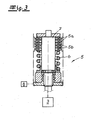
- the clutch 5 is formed as acted upon by a spring 6 multi-plate clutch.
- the clutch 5 has both stationary friction plates 5a and movable friction plates 5b.
- a movable plate package 5a and a stationary plate package 5b are realized.
- the movable friction plate 5a and the movable friction plate 5a is connected to the motor vehicle side door 1 and moves together with this. Also connected to the movable Reiblamellenver 5a or a shaft 7 connected thereto, the motor or electric motor 3 is connected. Rotations of the motor or electric motor 3 thus cause the shaft 7 also rotates and with it the movable plate pack 5a. As a result, the motor vehicle closing device 1 connected to the movable plate package 5a is acted upon accordingly, namely, the motor vehicle side door 1 is opened and closed. Depending on how strong the stationary plate package 5b is applied to the movable plate package 5a, the movement of the motor vehicle closing device 1 can be decelerated. For this purpose, an adjustable slip of the clutch 5 and adjustable self-locking forces of the entire drive correspond.
- the stationary disc pack 5b can now be employed more or less to the movable disc pack 5a.
- the slip of the clutch 5 can be changed. That is, with the aid of the servo motor 8, the self-locking forces of the drive for the motor vehicle locking device 1 can be varied and adjusted. In this way it is possible to convert the clutch 5 into a complete or at least partial disengaging condition and, of course, a coupling condition.
- the Auskuppelschreib is always selected when the motor vehicle locking device 1 is manually applied by an operator or should be. In this case, the disengagement state in question is taken according to the invention in accordance with an operator request.
- the operator request can now be transferred to the complete or at least partial disengaging state of the clutch 5 in basically two different ways.
- the operator's request can initially be transmitted via a mechanical actuating lever chain 2, 9, 10 to the clutch 5 for taking the AuskuppelSches.
- the actuating lever chain 2, 9, 10 in the illustrated example on the already mentioned inner door handle 2.
- an outside door handle 9 may be provided. Both handles 2, 9 are connected via one or more connecting members 10 with the coupling 5 in connection.
- the connecting links 10 connected to the respective handle 2, 9 may ensure that the stationary disk pack 5b is or will not be adjusted more or less strongly to the movable disk pack 5a by means of the spring 6. That is, the connecting members 10 between the outer door handle 9 and / or the inner door handle 2 ensure that the clutch 5 or its stationary plate pack 5b is acted upon accordingly - independently or in addition to the servomotor. 8
- the user request can also be queried with the aid of a sensor 11.
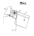
- the sensor 11 may be assigned to the outer door handle 9 in the embodiment. According to a particularly preferred embodiment, however, the sensor 11 is in a door frame, which is the motor vehicle side door 1 is assigned. That represents the Fig. 1 In this case, an arrangement of the sensor 11 on the frame or door frame has been found to be favorable, if in this case the above the outer door handle 9 arranged part of the door frame is taken into account. Because motor vehicle users tend to apply this area when moving motor vehicle side doors 1.
- the senor 11 detects when an operator grasps the door frame or, alternatively, the outer door handle 9. As a result, the sensor 11 ensures that with the help of the clutch 5 alternately associated servo motor 8, the stationary Lammelken 5b is made to the movable plate package 5a or separated from it. Following this, the clutch 5 can be converted into the complete or at least partial disengaging state, and the motor vehicle side door 1 can be moved manually. This applies to the case that the sensor 11 has been triggered. When not triggered sensor 11, the clutch 5, however, is in the engaged state.
- the sensor 11 or switch 11 can be a touch sensor or else a proximity sensor. Alternatively, the sensor 11 can of course be arranged elsewhere on the outside of the motor vehicle body 4 and / or in its interior.
- a control unit 12 is provided.
- this control unit 12 for example, a distinction can be made between a motor actuation of the motor vehicle closing device 1 initiated by a remote request and a manual actuation of the motor vehicle closing device 1. The latter usually takes place when the remote inquiry is omitted and / or suppressed or when the command is selected accordingly.
- This remote inquiry can be represented by means of a remote control or the like. In this way, the operator can practically remotely his operator's request express, namely, whether the motor vehicle locking device 1 should be operated by a motor or manually.
- the slippage of the stationary plate pack 5b in comparison to the movable plate packet 5a can be varied within the scope of the operator's request. This is done in the context of the embodiment with the aid of the servomotor 8, which 5b or the stationary plate package 5b more or less with the interposition of the spring 6 to the movable plate 5a and the movable plate package 5a sets the stationary plate 5b. In this way, the slip of the clutch 5 can be changed.
- the invention takes into account, for example, external circumstances when the motor vehicle is parked on a gradient or uphill section. In this case, one will set the slip so that the motor vehicle side door 1, for example, maintains its manually or motor-open position and is not closed as a result of the attacking forces.
- another sensor 13 detects, for example, the inclination of the motor vehicle body. Depending on this inclination, the slip between the stationary disc pack 5b and the movable disc pack 5a can then be varied. In this case, one will usually choose the design so that the greater the slope, the greater the self-locking forces of the clutch 5 are set.
- the senor 13 may also be formed as a distance sensor on the respective motor vehicle side door 1 to be actuated. With its help, then the opening and closing movement can be monitored. It will make the design so that, for example, the motor or electric motor 3 is stopped in an opening operation of the vehicle door side door 1, as soon as an obstacle opposes another opening movement. The same applies to any closing movements. This is summarized by the control unit 12.
Landscapes
- Power-Operated Mechanisms For Wings (AREA)
- Lock And Its Accessories (AREA)
Abstract
Description
- Die Erfindung betrifft eine Vorrichtung und ein Verfahren zur Betätigung einer Kraftfahrzeug-Schließeinrichtung, insbesondere einer Kraftfahrzeug-Seitentür, einer Kraftfahrzeug-Heckklappe, einer Kraftfahrzeugtankklappe, einer Kraftfahrzeug-Schiebetür oder dergleichen, mit einem Motor, insbesondere Elektromotor, und mit einer zwischen dem Motor und der Kraftfahrzeug-Schließeinrichtung zwischengeschalteten Kupplung, welche zur manuellen Beaufschlagung der Kraftfahrzeug-Schließeinrichtung durch einen Bediener in einen vollständigen oder teilweisen Auskuppelzustand überführt wird.
- Bei einer Vorrichtung des eingangs beschriebenen Aufbaus entsprechend der
EP 1 795 685 A2 lässt sich die Kupplung in einen Kuppelzustand und einen Lösezustand bringen. Zusätzlich ist ein Zwischen-Kuppelzustand mit reduziertem Übertragungsmoment bzw. mit reduzierter Übertragungskraft vorgesehen. Auf diese Weise kann die Kraftfahrzeugtür bei im Zwischen-Kuppelzustand befindlicher Kupplung durch die Selbsthemmung der Motoreinheit jederzeit in ihrer aktuellen Position gehalten werden. Sie lässt sich aber dennoch durch eine manuelle Betätigung mit einer vorbestimmten Mindest-Betätigungskraft verstellen. Dadurch soll zusammenfassend das Betriebsverhalten einer zugehörigen Antriebsanordnung im Notfall, beispielsweise bei Ausfall der Spannungsversorgung, optimiert werden. - Die beschriebene Vorgehensweise hat sich grundsätzlich bewährt, stößt allerdings dann an Grenzen, wenn eine manuelle Betätigung der Kraftfahrzeug-Schließeinrichtung auch unabhängig vom Notfall - also losgelöst vom Wegfall der Spannungsversorgung - vorgenommen werden soll. Grundsätzlich ist die motorische und insbesondere elektromotorische Betätigung von Kraftfahrzeug-Schließeinrichtungen besonders komfortabel. Denn das Gewicht von Kraftfahrzeug-Schließeinrichtungen, insbesondere Kraftfahrzeug-Seitentüren, ist nicht unerheblich. Das lässt sich im Kern darauf zurückführen, dass zahlreiche Zusatzaggregate in den betreffenden Kraftfahrzeug-Seitentüren platziert werden, wie beispielsweise Seitenairbags, Seitenaufprallverstärkungen, Lautsprecher, Fensterheber etc.. Vor diesem Hintergrund bestand und besteht ein zunehmendes Bedürfnis dahingehend, für eine motorische Betätigung der Kraftfahrzeug-Schließeinrichtung zu sorgen. Das gilt natürlich nicht nur für Kraftfahrzeug-Seitentüren, sondern genauso gut auch für Kraftfahrzeug-Heckklappen, Kraftfahrzeug-Schiebetüren etc..
- Da Bediener an solche motorisch betätigten bzw. elektromotorisch betätigten Schließeinrichtungen noch nicht umfassend gewöhnt sind, ergibt sich oftmals das Problem, dass Bediener, besonders Fremdbediener, die Kraftfahrzeug-Schließeinrichtung unverändert manuell beaufschlagen (wollen). Das führt zu erhöhten Bedienkräften, weil das zugehörige Antriebssystem aufgrund der innewohnenden Selbsthemmung relativ schwergängig ist. Aus diesem Grund hat man hier bereits eine zwischen dem Motor und der Kraftfahrzeug-Schließeinrichtung zwischengeschaltete Kupplung vorgesehen, welche entsprechend dem gattungsbildenden Stand der Technik zur manuellen Beaufschlagung der Kraftfahrzeug-Schließeinrichtung durch einen Bediener in einen vollständigen oder teilweisen Auskuppelzustand überführt wird. Das geschieht im Rahmen der gattungsbildenden Lehre nach der
EP 1 795 685 A2 jedoch nur im Notfall. Hier setzt die Erfindung ein. - Der Erfindung liegt das technische Problem zugrunde, eine derartige Vorrichtung so weiter zu entwickeln, dass eine problemlose alternative manuelle Beaufschlagung der Kraftfahrzeug-Schließeinrichtung praktisch zu jeder Zeit möglich ist. Außerdem soll ein entsprechendes Verfahren zur Betätigung einer solchen Kraftfahrzeug-Schließeinrichtung angegeben werden.
- Zur Lösung dieser technischen Problemstellung ist bei einer gattungsgemäßen Vorrichtung zur Betätigung einer Kraftfahrzeug-Schließeinrichtung im Rahmen der Erfindung vorgesehen, dass der Auskuppelzustand nach Maßgabe eines Bedienerwunsches bzw. dem Bedienerwunsch folgend eingenommen wird.
- Im Rahmen der Erfindung hängt der vollständige oder zumindest teilweise Auskuppelzustand also nicht von der Bordspannung im Kraftfahrzeug ab, wie dies der gattungsbildende Stand der Technik nach der
EP 1 795 685 A2 lehrt, sondern letztlich (und ausschließlich) vom Bedienerwunsch. Das heißt, der Bediener gibt vor, ob die Kupplung in den vollständigen oder doch zumindest teilweisen Auskuppelzustand überführt wird, und zwar in der Regel durch eine entsprechende Beaufschlagung der Kraftfahrzeug-Schließeinrichtung bzw. des Kraftfahrzeuges. Es ist aber auch möglich, dass der Bedienerwunsch durch Abfrage wenigstens eines Sensors registriert wird. Nach vorteilhafter Ausgestaltung befindet sich dieser den Bedienerwunsch registrierende Sensor im Bereich eines Türrahmens. Er mag also beispielsweise an einer A- und/oder B-Säule angeordnet sein. Dabei hat sich als besonders bevorzugt eine Anordnung des Sensors erwiesen, bei welcher dieser im Bereich des Türrahmens angeordnet ist, welcher sich Oberhalb einer gedachten und durch den Türgriff definierten Linie erstreckt. Tatsächlich wird dieser Bereich von vielen Kraftfahrzeugnutzern wie selbstverständlich zum beispielsweise "Zuschlagen" von Kraftfahrzeugs-Seitentüren benutzt. - Bei Verwendung eines Sensors zur Registrierung des Bedienerwunsches mündet dieser und das zugehörige Sensorsignal in der Regel in eine motorische Stellbewegung. Mit Hilfe dieser motorischen Stellbewegung wird die Kupplung beaufschlagt und in den gewünschten Auskoppelzustand überprüft. Ohne diesen Bedienerwunsch befindet sich die Kupplung im Einkuppelzustand. Alternativ zu der sensorischen Abfrage kann der Bedienerwunsch aber auch über eine mechanische Betätigungshebelkette auf die Kupplung zur Einnahme des Auskuppelzustandes übertragen werden. Dabei beinhaltet die mechanische Betätigungshebelkette in der Regel wenigstens einen Außentürgriff und/oder einen Innentürgriff. Sobald nun der Außentürgriff und/oder der Innentürgriff von dem Bediener beaufschlagt werden, sorgt die entsprechende Betätigung dafür, dass eine oder mehrere an den Außentürgriff und/oder den Innentürgriff angeschlossene Verbindungsglieder die Kupplung direkt beaufschlagen und in den vollständigen oder zumindest teilweisen Auskuppelzustand überführen.
- Sofern der Bedienerwunsch nicht über die beschriebene mechanische Betätigungshebelkette auf die Kupplung übertragen wird, sondern durch die Abfrage wenigstens eines Sensors, empfiehlt es sich, wenn der fragliche Sensor als Schalter, Berührsensor oder Näherungssensor ausgebildet ist. Der Sensor kann beispielsweise einem Türgriff zugeordnet sein oder sich in dessen Nähe befinden. Selbstverständlich liegt es auch im Rahmen der Erfindung, wenn der fragliche Sensor im Innern des Kraftfahrzeuges angebracht ist, beispielsweise an einem Armaturenbrett. Dadurch kann der Bediener insgesamt seinen Wunsch kundtun, die Kraftfahrzeug-Schließeinrichtung manuell beaufschlagen zu wollen. Das heißt, der Sensor lässt sich außen an der Kraftfahrzeugkarosserie und/oder in ihrem Innern anordnen.
- Darüber hinaus schlägt die Erfindung eine Steuereinheit vor, mit deren Hilfe zwischen einer durch eine Fernabfrage initiierten motorischen Betätigung der Kraftfahrzeug-Schließeinrichtung und einer manuellen Betätigung der Kraftfahrzeug-Schließeinrichtung bei beispielsweise unterbliebener und/oder unterdrückter Fernabfrage unterschieden werden kann. Das heißt, die Erfindung eröffnet die Möglichkeit, die Kraftfahrzeug-Schließeinrichtung im Rahmen einer Fernabfrage motorisch zu betätigen. Dabei kann die Fernabfrage mit einem Frage-/Antwortdialog flankiert werden, welcher zur Identifizierung des Bedieners und seiner Zugriffsberechtigung auf das Kraftfahrzeug dient.
- Üblicherweise werden nach einer solchen Fernabfrage und der erfolgreichen Identifizierung des Bedieners sämtliche Kraftfahrzeugtürschlösser entriegelt. Im Rahmen der Erfindung kann dieser Vorgang nun noch dadurch flankiert werden, dass bei Bedarf beispielsweise die Kraftfahrzeug-Fahrertür motorisch geöffnet wird und zwar das zugehörige und entriegelte Kraftfahrzeug-Türschloss ebenfalls eine Öffnung erfahren hat. Unterbleibt jedoch die Fernabfrage oder wird unterdrückt, so wird im Allgemeinen davon ausgegangen, dass die Kraftfahrzeug-Schließeinrichtung von dem Bediener manuell beaufschlagt werden soll. Das ist beispielsweise dann denkbar, wenn sich das Kraftfahrzeug in einer Parklücke befindet und die ausschwenkende Kraftfahrzeug-Fahrertür ein benachbartes Fahrzeug beschädigen würde. Jedenfalls kann ein Bediener durch die beschriebene Fernabfrage zwischen den verschiedenen Betriebszuständen unterscheiden, nämlich im Wesentlichen der motorischen Betätigung der Kraftfahrzeug-Schließeinrichtung und ihrer manuellen Betätigung.
- Im Detail ist die zwischen dem Motor bzw. Elektromotor und der Kraftfahrzeug-Schließeinrichtung zwischengeschaltete Kupplung als von einer Feder beaufschlagte Lamellenkupplung ausgeführt. Die fragliche Kupplung verfügt über wenigstens eine stationäre und eine bewegliche Reiblamelle. Meistens sind jeweils Lamellenpakete realisiert, nämlich ein stationäres Lamellenpaket und ein bewegliches Lamellenpaket, die sich im Innern der Kupplung jeweils abwechseln. Dabei sind im Allgemeinen die eine bewegliche Reiblamelle bzw. die mehreren beweglichen Reiblamellen an die Kraftfahrzeug-Schließeinrichtung angeschlossen. Dementsprechend werden die beweglichen Reiblamellen zusammen mit der Kraftfahrzeug-Schließeinrichtung mitbewegt. Dagegen wird die eine stationäre Reiblamelle bzw. werden die mehreren stationären Reiblamellen durch den Bedienerwunsch an die bewegliche Reiblamelle bzw. die mehreren beweglichen Reiblamellen angestellt. Das kann motorisch erfolgen, und zwar durch einen der Kupplung zugeordneten Stellmotor, welcher entsprechende motorische Stellbewegungen absolviert. Es ist aber auch möglich, dass die den Bedienerwunsch alternativ umsetzende mechanische Betätigungshebelkette dafür sorgt, dass die stationäre Reiblamelle an die bewegliche Reiblamelle angestellt wird. Das kann insgesamt mit einstellbarem Schlupf geschehen.
- Dabei lässt sich der Schlupf in Abhängigkeit vom Bedienerwunsch sowie äußeren Gegebenheiten unterschiedlich vorgeben. Das heißt, der Bediener kann letztlich die der manuellen Bewegung entgegengebrachten Selbsthemmungskräfte der erfindungsgemäßen Vorrichtung einstellen. Das ist von besonderer Bedeutung für den Fall, dass beispielsweise die Kraftfahrzeug-Schließeinrichtung respektive Kraftfahrzeug-Seitentür nicht nur manuell geöffnet werden, sondern auch ihre Öffnungsposition beibehalten soll, beispielsweise an einer Gefällestrecke. Das heißt, je nach dem Bedienerwunsch bzw. den äußeren Gegebenheiten, im vorliegenden Fall in Abhängigkeit vom Gefälle, kann der Schlupf der Kupplung zwischen dem Motor und der Kraftfahrzeug-Schließeinrichtung unterschiedlich eingestellt werden. Das lässt sich im einfachsten Fall dadurch bewerkstelligen, dass der der Kupplung zugeordnete Stellmotor dafür sorgt, dass die eine stationäre Reiblamelle bzw. die mehreren stationären Reiblamellen mehr oder minder an die bewegliche bzw. die mehreren beweglichen Reiblamellen angestellt werden. Selbstverständlich ist diese Schlupfeinstellung auch rein mechanisch realisierbar.
- Gegenstand der Erfindung ist auch ein Verfahren zur Betätigung einer solchen Kraftfahrzeug-Schließeinrichtung. In diesem Zusammenhang können ein Bediener und/oder ein weiterer Sensor den Schlupf der Kupplung vorgeben. Bei diesem weiteren Sensor mag es sich nur beispielhaft und nicht einschränkend um einen Neigungssensor handeln, welcher im beschriebenen Beispielfall feststellt, ob sich das Kraftfahrzeug an einer Gefällestrecke befindet oder nicht. Außerdem ist die Auslegung so getroffen, dass die Kupplung bei in Schließposition befindlicher Kraftfahrzeug-Schließeinrichtung in jedem Fall in ihren Einkuppelzustand überführt wird. Dadurch ist gewährleistet, dass während der Fahrt oder bei einem Unfall die Tür - zusätzlich zu etwaigen weiteren Einrichtungen, wie beispielsweise einer Zuziehhilfe - sicher ihre geschlossene Position beibehält, so dass ein maximaler Unfallschutz gegeben ist. Hierin sind die wesentlichen Vorteile zu sehen.
- Im Folgenden wird die Erfindung anhand einer lediglich ein Ausführungsbeispiel darstellenden Zeichnung näher erläutert; es zeigen:
- Fig. 1
- die erfindungsgemäße Vorrichtung in einer Übersicht,
- Fig. 2
- ein Detail aus
Fig. 1 und - Fig. 3
- die Kupplung im Einzelnen.
- In den Figuren ist eine Vorrichtung zur Betätigung einer Kraftfahrzeug-Schließeinrichtung 1, insbesondere einer Kraftfahrzeug-Seitentür 1, dargestellt. Die Kraftfahrzeug-Seitentür 1 lässt sich im Rahmen der Erfindung sowohl motorisch als auch manuell beaufschlagen. Dazu ist die Kraftfahrzeug-Schließeinrichtung 1 bzw. Kraftfahrzeug-Seitentür 1 sowohl mit einer Handhabe 2, 9 als auch mit einem Motor 3, insbesondere Elektromotor 3, ausgerüstet.
- Im Rahmen des dargestellten Beispiels findet sich der Motor bzw. Elektromotor 3 im Bereich eines Scharniers respektive einer Anlenkung der Kraftfahrzeugtür 1 an eine Kraftfahrzeugkarosserie 4. Zwischen dem Elektromotor 3 und der Kraftfahrzeug-Schließeinrichtung bzw. Kraftfahrzeug-Seitentür 1 ist eine Kupplung 5 zwischengeschaltet. Die Kupplung 5 ist als von einer Feder 6 beaufschlagte Lamellenkupplung ausgebildet. Tatsächlich verfügt die Kupplung 5 sowohl über stationäre Reiblamellen 5a als auch bewegliche Reiblamellen 5b. Im Rahmen des Ausführungsbeispiels sind ein bewegliches Lamellenpaket 5a und ein stationäres Lamellenpaket 5b realisiert.
- Die bewegliche Reiblamelle 5a bzw. das bewegliche Reiblamellenpaket 5a ist an die Kraftfahrzeug-Seitentür 1 angeschlossen und bewegt sich zusammen mit dieser. Ebenfalls an das bewegliche Reiblamellenpaket 5a bzw. eine hiermit verbundene Welle 7 ist der Motor respektive Elektromotor 3 angeschlossen. Rotationen des Motors bzw. Elektromotors 3 führen also dazu, dass die Welle 7 ebenfalls rotiert und mit ihr das bewegliche Lamellenpaket 5a. Als Folge hiervon wird die mit dem beweglichen Lamellenpaket 5a verbundene Kraftfahrzeug-Schließeinrichtung 1 entsprechend beaufschlagt, nämlich die Kraftfahrzeug-Seitentür 1 geöffnet und geschlossen. Je nachdem, wie stark das stationäre Lamellenpaket 5b an das bewegliche Lamellenpaket 5a angelegt wird, lässt sich die Bewegung der Kraftfahrzeug-Schließeinrichtung 1 abbremsen. Dazu korrespondieren ein einstellbarer Schlupf der Kupplung 5 sowie einstellbare Selbsthemmungskräfte des gesamten Antriebes.
- Mit Hilfe eines Stellmotors 8 kann nun das stationäre Lamellenpaket 5b mehr oder minder an das bewegliche Lamellenpaket 5a angestellt werden. Dadurch lässt sich der Schlupf der Kupplung 5 verändern. Das heißt, mit Hilfe des Stellmotors 8 können die Selbsthemmungskräfte des Antriebes für die Kraftfahrzeug-Schließeinrichtung 1 variiert und eingestellt werden. Auf diese Weise ist es möglich, die Kupplung 5 in einen vollständigen oder zumindest teilweisen Auskuppelzustand und natürlich einen Einkuppelzustand zu überführen. Der Auskuppelzustand wird immer dann gewählt, wenn die Kraftfahrzeug-Schließeinrichtung 1 durch einen Bediener manuell beaufschlagt wird oder werden soll. Dabei wird der fragliche Auskuppelzustand erfindungsgemäß nach Maßgabe eines Bedienerwunsches eingenommen.
- Der Bedienerwunsch kann nun auf grundsätzlich zwei verschiedene Arten und Weisen in den vollständigen oder zumindest teilweisen Auskuppelzustand der Kupplung 5 überführt werden. Tatsächlich lässt sich der Bedienerwunsch zunächst einmal über eine mechanische Betätigungshebelkette 2, 9, 10 auf die Kupplung 5 zur Einnahme des Auskuppelzustandes übertragen. Zu diesem Zweck verfügt die Betätigungshebelkette 2, 9, 10 im Rahmen des dargestellten Beispieles über den bereits angesprochenen Innentürgriff 2. Zusätzlich mag ein Außentürgriff 9 vorgesehen sein. Beide Griffe 2, 9 stehen über ein oder mehrere Verbindungsglieder 10 mit der Kupplung 5 in Verbindung.
- Indem nun ein Bediener den Innentürgriff 2 und/oder Außentürgriff 9 beaufschlagt, wird über die an dem betreffenden Griff 2, 9 angeschlossenen Verbindungsglieder 10 bzw. das eine Verbindungsglied 10 die Kupplung 5 in den vollständigen oder zumindest teilweisen Auskuppelzustand überführt.
- Tatsächlich mögen die mit dem jeweiligen Griff 2, 9 verbundenen Verbindungsglieder 10 dafür sorgen, dass das stationäre Lamellenpaket 5b mehr oder minder stark an das bewegliche Lamellenpaket 5a mit Hilfe der Feder 6 angestellt wird oder nicht. Das heißt, die Verbindungsglieder 10 zwischen dem Außentürgriff 9 und/oder dem Innentürgriff 2 sorgen dafür, dass die Kupplung 5 bzw. deren stationäres Lamellenpaket 5b entsprechend beaufschlagt wird - unabhängig oder zusätzlich zum Stellmotor 8.
- Alternativ hierzu kann der Bedienerwunsch aber auch mit Hilfe eines Sensors 11 abgefragt werden. Der Sensor 11 mag im Ausführungsbeispiels dem Außentürgriff 9 zugeordnet sein. Nach besonders bevorzugter Ausführungsgestaltung findet sich der Sensor 11 jedoch in einem Türrahmen, welcher der Kraftfahrzeug-Seitentür 1 zugeordnet ist. Das stellt die
Fig. 1 dar. Dabei hat sich eine Anordnung des Sensors 11 am Rahmen bzw. Türrahmen als günstig erwiesen, wenn in diesem Fall der oberhalb des Außentürgriffes 9 angeordnete Teil des Türrahmens Berücksichtigung findet. Denn Kraftfahrzeugnutzer neigen dazu, diesen Bereich beim Bewegen von Kraftfahrzeug-Seitentüren 1 zu beaufschlagen. - In jedem Fall erkennt der Sensor 11, sobald ein Bediener den Türrahmen oder alternativ hierzu den Außentürgriff 9 ergreift. Als Folge hiervon sorgt der Sensor 11 dafür, dass mit Hilfe des der Kupplung 5 alternativ zugeordneten Stellmotors 8 das stationäre Lammelpaket 5b an das bewegliche Lamellenpaket 5a angestellt oder von diesem getrennt wird. Hieran anschließend lässt sich die Kupplung 5 in den vollständigen oder zumindest teilweisen Auskuppelzustand überführen und kann die Kraftfahrzeug-Seitentür 1 manuell bewegt werden. Das gilt für den Fall, dass der Sensor 11 ausgelöst wurde. Bei nicht ausgelöstem Sensor 11 befindet sich die Kupplung 5 dagegen im Einkuppelzustand.
- Bei dem Sensor 11 bzw. Schalter 11 kann es sich um einen Berührsensor oder auch einen Näherungssensor handeln. Alternativ hierzu lässt sich der Sensor 11 natürlich auch an anderer Stelle außen an der Kraftfahrzeugkarosserie 4 und/oder in ihrem Innern anordnen.
- Schlussendlich ist noch eine Steuereinheit 12 vorgesehen. Mit Hilfe dieser Steuereinheit 12 kann beispielsweise zwischen einer durch eine Fernabfrage initiierten motorischen Betätigung der Kraftfahrzeug-Schließeinrichtung 1 und einer manuellen Betätigung der Kraftfahrzeug-Schließeinrichtung 1 unterschieden werden. Letztere erfolgt in der Regel bei unterbliebener und/oder unterdrückter Fernabfrage bzw. bei entsprechender Auswahl des Befehls. Diese Fernabfrage lässt sich mit Hilfe einer Fernbedienung oder dergleichen darstellen. Auf diese Weise kann der Bediener praktisch von Ferne seinen Bedienerwunsch äußern, nämlich dahingehend, ob die Kraftfahrzeug-Schließeinrichtung 1 motorisch oder manuell betätigt werden soll.
- Ganz abgesehen davon lässt sich im Rahmen des Bedienerwunsches der Schlupf des stationären Lamellenpakets 5b im Vergleich zum beweglichen Lamellenpaket 5a variieren. Das geschieht im Rahmen des Ausführungsbeispiels mit Hilfe des Stellmotors 8, welcher die stationäre Lamelle 5b bzw. das stationäre Lamellenpaket 5b mehr oder minder unter Zwischenschaltung der Feder 6 an die bewegliche Lamelle 5a respektive das bewegliche Lamellenpaket 5a anstellt. Auf diese Weise kann der Schlupf der Kupplung 5 verändert werden. Dadurch trägt die Erfindung beispielsweise äußeren Umständen Rechnung, wenn das Kraftfahrzeug an einer Gefälle- oder Steigungsstrecke geparkt ist. In diesem Fall wird man den Schlupf so einstellen, dass die Kraftfahrzeug-Seitentür 1 beispielsweise ihre manuell oder motorisch geöffnete Position beibehält und nicht in Folge der angreifenden Kräfte geschlossen wird.
- Denkbar ist es in diesem Zusammenhang, dass ein weiterer Sensor 13 beispielsweise die Neigung der Kraftfahrzeugkarosserie feststellt. In Abhängigkeit von dieser Neigung kann dann der Schlupf zwischen dem stationären Lamellenpaket 5b und dem beweglichen Lamellenpaket 5a variiert werden. Dabei wird man die Auslegung meistens so wählen, dass je größer die Steigung ist, desto größer auch die Selbsthemmungskräfte der Kupplung 5 eingestellt werden.
- Alternativ hierzu kann der Sensor 13 auch als Abstandssensor an der jeweils zu betätigenden Kraftfahrzeug-Seitentür 1 ausgebildet sein. Mit dessen Hilfe kann dann die Öffnungs- und Schließbewegung überwacht werden. Dabei wird mit die Auslegung so treffen, dass beispielsweise der Motor bzw. Elektromotor 3 bei einem Öffnungsvorgang der Kraftfahrzeugtür-Seitentür 1 gestoppt wird, sobald ein Hindernis einer weiteren Öffnungsbewegung entgegensteht. Das Gleiche gilt für etwaige Schließbewegungen. Hierfür sorgt zusammenfassend die Steuereinheit 12.
- Schlussendlich wird man die Kupplung 5 bei in Schließposition befindlicher Kraftfahrzeugseitentür 1 in der Regel in ihren Einkuppelzustand überführen. Dies deshalb, um - gegebenenfalls in Kombination mit einer Zuziehhilfe - für einen maximalen Unfallschutz zu sorgen und sicherzustellen, dass die Kraftfahrzeug-Seitentür in jedem Fall - auch bei einem Unfall - geschlossen bleibt.
Claims (15)
- Vorrichtung zur Betätigung einer Kraftfahrzeug-Schließeinrichtung (1), insbesondere einer Kraftfahrzeug-Seitentür (1), einer Kraftfahrzeug-Heckklappe oder dergleichen, mit einem Motor (3), insbesondere Elektromotor (3), und mit einer zwischen dem Motor (3) und der Kraftfahrzeug-Schließeinrichtung (1) zwischengeschalteten Kupplung (5), welche zur manuellen Beaufschlagung der Kraftfahrzeug-Schließeinrichtung (1) durch einen Bediener in einen vollständigen oder teilweisen Auskuppelzustand überführt wird, dadurch gekennzeichnet, dass der Auskuppelzustand nach Maßgabe eines Bedienerzustandes eingenommen wird.
- Vorrichtung nach Anspruch 1, dadurch gekennzeichnet, dass der Bedienerwunsch über eine mechanische Betätigungshebelkette (2, 9, 10) auf die Kupplung (5) zur Einnahme des Auskuppelzustandes übertragen wird.
- Vorrichtung nach Anspruch 1 oder 2, dadurch gekennzeichnet, dass die mechanische Betätigungshebelkette (2, 9, 10) wenigstens einen Außentürgriff (9) und/oder einen Innentürgriff (2) beinhaltet, die über ein oder mehrere Verbindungsglieder (10) die Kupplung (5) direkt beaufschlagen.
- Vorrichtung nach einem der Ansprüche 1 bis 3, dadurch gekennzeichnet, dass der Bedienerwunsch durch Abfrage wenigstens eines Sensors (11) registriert und in eine motorische Stellbewegung zur Beaufschlagung der Kupplung (5) umgesetzt wird.
- Vorrichtung nach Anspruch 4, dadurch gekennzeichnet, dass der Sensor (11) als Schalter, Berührsensor oder Näherungssensor ausgebildet ist, welcher beispielsweise einem Türgriff (2, 9) zugeordnet ist.
- Vorrichtung nach Anspruch 4 oder 5, dadurch gekennzeichnet, dass der Sensor (11) außen an einer Kraftfahrzeugkarosserie (4), insbesondere im Bereich eines Türrahmens, und/oder im Innern der Kraftfahrzeugkarosserie (4) angeordnet ist.
- Vorrichtung nach einem der Ansprüche 1 bis 6, dadurch gekennzeichnet, dass eine Steuereinheit (12) vorgesehen ist, welche beispielsweise zwischen einer durch eine Fernabfrage initiierten motorischen Betätigung der Kraftfahrzeug-Schließeinrichtung (1) und einer manuellen Betätigung der Kraftfahrzeug-Schließeinrichtung (1) unterscheidet.
- Vorrichtung nach einem der Ansprüche 1 bis 7, dadurch gekennzeichnet, dass die Kupplung (5) als von einer Feder (6) beaufschlagte Lamellenkupplung mit wenigstens einer stationären Reiblamelle (5b) und einer beweglichen Reiblamelle (5a) ausgerüstet ist.
- Vorrichtung nach Anspruch 8, dadurch gekennzeichnet, dass die bewegliche Reiblamelle (5a) an die Kraftfahrzeug-Schließeinrichtung (1) angeschlossen ist und zusammen mit dieser mitbewegt wird.
- Vorrichtung nach Anspruch 8 oder 9, dadurch gekennzeichnet, dass die stationäre Reiblamelle (5b) durch den Bedienerwunsch mit gegebenenfalls einstellbarem Schlupf an die bewegliche Reiblamelle (5a) angestellt wird.
- Vorrichtung nach Anspruch 10, dadurch gekennzeichnet, dass der Schlupf in Abhängigkeit vom Bedienerwunsch sowie äußeren Gegebenheiten, beispielsweise einer räumlichen Position der Kraftfahrzeugkarosserie (4) unterschiedlich eingestellt wird.
- Verfahren zur Betätigung einer Kraftfahrzeug-Schließeinrichtung (1), insbesondere einer Kraftfahrzeug-Seitentür (1), mit einem Motor (3), und mit einer zwischen dem Motor (3) und der Kraftfahrzeug-Schließeinrichtung (1) zwischengeschalteten Kupplung (5), welche in einen vollständigen oder teilweisen Auskuppelzustand überführt wird, damit ein Bediener die Kraftfahrzeug-Schließeinrichtung (1) unter Überwindung von Selbsthemmungskräften beaufschlagen kann, dadurch gekennzeichnet, dass die Kupplung (5) ihren Auskuppelzustand im Anschluss an einen Bedienerwunsch einnimmt.
- Verfahren nach Anspruch 12, dadurch gekennzeichnet, dass der Bediener zur Überführung der Kupplung (5) in den Auskuppelzustand eine mechanische Betätigungshebelkette und/oder wenigstens einen Sensor (11) mit hiervon beaufschlagtem Stellmotor (8) zur Ansteuerung der Kupplung (5) betätigt.
- Verfahren nach Anspruch 12 oder 13, dadurch gekennzeichnet, dass der Bediener und/oder ein weiterer Sensor (13) einen Schlupf der Kupplung (5) vorgeben.
- Verfahren nach einem der Ansprüche 12 bis 14, dadurch gekennzeichnet, dass die Kupplung (5) bei in Schließposition befindlicher Kraftfahrzeug-Schließeinrichtung (1) in ihren Einkuppelzustand überführt wird.
Applications Claiming Priority (1)
| Application Number | Priority Date | Filing Date | Title |
|---|---|---|---|
| DE102009014404A DE102009014404A1 (de) | 2009-03-26 | 2009-03-26 | Verfahren und Vorrichtung zur Betätigung einer Kraftfahrzeug-Schließeinrichtung |
Publications (3)
| Publication Number | Publication Date |
|---|---|
| EP2236719A2 true EP2236719A2 (de) | 2010-10-06 |
| EP2236719A3 EP2236719A3 (de) | 2014-05-14 |
| EP2236719B1 EP2236719B1 (de) | 2017-05-10 |
Family
ID=42316124
Family Applications (1)
| Application Number | Title | Priority Date | Filing Date |
|---|---|---|---|
| EP10002264.9A Active EP2236719B1 (de) | 2009-03-26 | 2010-03-05 | Verfahren und Vorrichtung zur Betätigung einer Kraftfahrzeug-Schließeinrichtung |
Country Status (2)
| Country | Link |
|---|---|
| EP (1) | EP2236719B1 (de) |
| DE (1) | DE102009014404A1 (de) |
Cited By (2)
| Publication number | Priority date | Publication date | Assignee | Title |
|---|---|---|---|---|
| DE102012024375A1 (de) | 2012-12-13 | 2014-06-18 | Kiekert Aktiengesellschaft | Vorrichtung und Verfahren zur Betätigung einer Kraftfahrzeug-Schließeinrichtung |
| WO2020156682A1 (en) * | 2019-02-01 | 2020-08-06 | Brose Fahrzeugteile Se & Co. Kommanditgesellschaft, Bamberg | Door drive device controllable for detecting a user action on a vehicle door |
Families Citing this family (3)
| Publication number | Priority date | Publication date | Assignee | Title |
|---|---|---|---|---|
| DE102012024931A1 (de) * | 2012-12-20 | 2014-06-26 | GM Global Technology Operations LLC (n. d. Ges. d. Staates Delaware) | Heckklappenssystem mit Öffnungswinkelbeschränkung |
| DE102017121150A1 (de) | 2017-09-13 | 2019-03-14 | Kiekert Ag | Kraftfahrzeugtür, insbesondere Kraftfahrzeugschiebetür |
| DE102018110708A1 (de) * | 2018-05-04 | 2019-04-11 | Schaeffler Technologies AG & Co. KG | Aktuatoranordnung zur Betätigung eines schwenkbaren Bauteils gegenüber einem ortsfesten Bauteil und Verfahren zur Steuerung der Aktuatoranordnung |
Citations (1)
| Publication number | Priority date | Publication date | Assignee | Title |
|---|---|---|---|---|
| EP1795685A2 (de) | 2005-12-07 | 2007-06-13 | Brose Schliesssysteme GmbH & Co. KG | Antriebsanordnung zur motorischen Verstellung einer Kraftfahrzeugtür o.dgl. |
Family Cites Families (4)
| Publication number | Priority date | Publication date | Assignee | Title |
|---|---|---|---|---|
| US4121382A (en) * | 1977-07-14 | 1978-10-24 | Dietrich Edward J | Mechanized door operating means for a motor vehicle |
| US20020180237A1 (en) * | 2001-06-04 | 2002-12-05 | Rogers Lloyd W. | Drive mechanism for power operated slideable side door and roller and hinge assembly therefor |
| DE102005004571B4 (de) * | 2005-02-01 | 2008-12-11 | Innotec Forschungs- Und Entwicklungs-Gmbh | Kraftunterstütztes Fahrzeugscharnier |
| DE102007027867A1 (de) * | 2007-06-18 | 2008-12-24 | Continental Automotive Gmbh | Verfahren und Anordnung zur Ansteuerung zumindest einer elektromechanischen Bremsaktuatoreinheit einer Türbremseinrichtung |
-
2009
- 2009-03-26 DE DE102009014404A patent/DE102009014404A1/de not_active Ceased
-
2010
- 2010-03-05 EP EP10002264.9A patent/EP2236719B1/de active Active
Patent Citations (1)
| Publication number | Priority date | Publication date | Assignee | Title |
|---|---|---|---|---|
| EP1795685A2 (de) | 2005-12-07 | 2007-06-13 | Brose Schliesssysteme GmbH & Co. KG | Antriebsanordnung zur motorischen Verstellung einer Kraftfahrzeugtür o.dgl. |
Cited By (6)
| Publication number | Priority date | Publication date | Assignee | Title |
|---|---|---|---|---|
| DE102012024375A1 (de) | 2012-12-13 | 2014-06-18 | Kiekert Aktiengesellschaft | Vorrichtung und Verfahren zur Betätigung einer Kraftfahrzeug-Schließeinrichtung |
| WO2014090222A1 (de) | 2012-12-13 | 2014-06-19 | Kiekert Aktiengesellschaft | VORRICHTUNG UND VERFAHREN ZUR BETÄTIGUNG EINER KRAFTFAHRZEUG-SCHLIEßEINRICHTUNG |
| CN105008643A (zh) * | 2012-12-13 | 2015-10-28 | 开开特股份公司 | 用于操纵机动车闭锁装置的设备和方法 |
| US20150330134A1 (en) * | 2012-12-13 | 2015-11-19 | Kiekert Aktiengesellschaft | Device and method for actuating a motor vehicle closing device |
| JP2016506463A (ja) * | 2012-12-13 | 2016-03-03 | キーケルト アクツィーエンゲゼルシャフト | 自動車閉鎖装置を作動させるための装置及び方法 |
| WO2020156682A1 (en) * | 2019-02-01 | 2020-08-06 | Brose Fahrzeugteile Se & Co. Kommanditgesellschaft, Bamberg | Door drive device controllable for detecting a user action on a vehicle door |
Also Published As
| Publication number | Publication date |
|---|---|
| EP2236719A3 (de) | 2014-05-14 |
| DE102009014404A1 (de) | 2010-09-30 |
| EP2236719B1 (de) | 2017-05-10 |
Similar Documents
| Publication | Publication Date | Title |
|---|---|---|
| EP3942138B1 (de) | Aufstellvorrichtung für ein kraftfahrzeugtürelement | |
| DE102018203239A1 (de) | Kraft-schwenktür-antriebsbetätigungsglied | |
| DE202012003171U1 (de) | Kraftfahrzeugtürverschluss | |
| DE112008002316T5 (de) | System und Verfahren zum dynamischen Bremsen eines Fahrzeugverschlusssystems | |
| DE102011100552A1 (de) | Fahrzeugtürschloss | |
| EP3807482B1 (de) | Kraftfahrzeugtürverschluss | |
| EP1604086A2 (de) | Kraftfahrzeug | |
| DE102017124359A1 (de) | System und verfahren zur steuerung einer fensteranordnung eines fahrzeugs | |
| EP2236719B1 (de) | Verfahren und Vorrichtung zur Betätigung einer Kraftfahrzeug-Schließeinrichtung | |
| DE60208638T2 (de) | Eine Aktuatoreinheit | |
| DE102011119579A1 (de) | Vorrichtung zur elektromotorischen Betätigung einer Tür | |
| DE102021109277A1 (de) | Verriegelungsmechanismus für eine verschlussplatte mit mehreren verriegelungen | |
| DE102016115439A1 (de) | Kraftfahrzeugschlossanordnung | |
| EP4036357B1 (de) | Notöffnung einer fahrzeugtür | |
| EP3027828B1 (de) | Kraftfahrzeugtür | |
| DE102011113174A1 (de) | Verfahren zum Öffnen einer rahmenlosen Fahrzeugtüre | |
| DE102019112398A1 (de) | Aufstellvorrichtung für ein Kraftfahrzeugtürelement | |
| DE102009018188A1 (de) | Vorrichtung zum automatischen Schließen einer Fahrzeugtür | |
| DE102016121189A1 (de) | Betätigungseinrichtung für automatische Anwendungen | |
| DE102022129411A1 (de) | System zur Betätigung einer beweglichen Scheibe | |
| DE102008026040A1 (de) | Verfahren und Vorrichtung zur motorischen Verstellung einer Kraftfahrzeugtür | |
| EP3695083A1 (de) | Kraftfahrzeugtür, insbesondere kraftfahrzeugschiebetür | |
| DE102006020344A1 (de) | Schließsystem für eine Kraftfahrzeugtür mit mehreren Schließelementen und gemeinsamer Steuereinheit | |
| EP1812671B1 (de) | Kombinierte schliesseinrichtung | |
| WO2021073888A1 (de) | Betätigungsvorrichtung sowie verfahren zum betreiben einer betätigungsvorrichtung |
Legal Events
| Date | Code | Title | Description |
|---|---|---|---|
| PUAI | Public reference made under article 153(3) epc to a published international application that has entered the european phase |
Free format text: ORIGINAL CODE: 0009012 |
|
| AK | Designated contracting states |
Kind code of ref document: A2 Designated state(s): AT BE BG CH CY CZ DE DK EE ES FI FR GB GR HR HU IE IS IT LI LT LU LV MC MK MT NL NO PL PT RO SE SI SK SM TR |
|
| AX | Request for extension of the european patent |
Extension state: AL BA ME RS |
|
| PUAL | Search report despatched |
Free format text: ORIGINAL CODE: 0009013 |
|
| AK | Designated contracting states |
Kind code of ref document: A3 Designated state(s): AT BE BG CH CY CZ DE DK EE ES FI FR GB GR HR HU IE IS IT LI LT LU LV MC MK MT NL NO PL PT RO SE SI SK SM TR |
|
| AX | Request for extension of the european patent |
Extension state: AL BA ME RS |
|
| RIC1 | Information provided on ipc code assigned before grant |
Ipc: E05F 15/12 20060101AFI20140409BHEP |
|
| 17P | Request for examination filed |
Effective date: 20150226 |
|
| RBV | Designated contracting states (corrected) |
Designated state(s): AT BE BG CH CY CZ DE DK EE ES FI FR GB GR HR HU IE IS IT LI LT LU LV MC MK MT NL NO PL PT RO SE SI SK SM TR |
|
| 17Q | First examination report despatched |
Effective date: 20160302 |
|
| REG | Reference to a national code |
Ref country code: DE Ref legal event code: R079 Ref document number: 502010013565 Country of ref document: DE Free format text: PREVIOUS MAIN CLASS: E05F0015120000 Ipc: E05F0015611000 |
|
| RIC1 | Information provided on ipc code assigned before grant |
Ipc: E05F 15/611 20150101AFI20160926BHEP |
|
| GRAP | Despatch of communication of intention to grant a patent |
Free format text: ORIGINAL CODE: EPIDOSNIGR1 |
|
| INTG | Intention to grant announced |
Effective date: 20161107 |
|
| GRAS | Grant fee paid |
Free format text: ORIGINAL CODE: EPIDOSNIGR3 |
|
| GRAA | (expected) grant |
Free format text: ORIGINAL CODE: 0009210 |
|
| AK | Designated contracting states |
Kind code of ref document: B1 Designated state(s): AT BE BG CH CY CZ DE DK EE ES FI FR GB GR HR HU IE IS IT LI LT LU LV MC MK MT NL NO PL PT RO SE SI SK SM TR |
|
| REG | Reference to a national code |
Ref country code: GB Ref legal event code: FG4D Free format text: NOT ENGLISH |
|
| REG | Reference to a national code |
Ref country code: AT Ref legal event code: REF Ref document number: 892515 Country of ref document: AT Kind code of ref document: T Effective date: 20170515 Ref country code: CH Ref legal event code: EP |
|
| REG | Reference to a national code |
Ref country code: IE Ref legal event code: FG4D Free format text: LANGUAGE OF EP DOCUMENT: GERMAN |
|
| REG | Reference to a national code |
Ref country code: DE Ref legal event code: R096 Ref document number: 502010013565 Country of ref document: DE |
|
| REG | Reference to a national code |
Ref country code: NL Ref legal event code: MP Effective date: 20170510 |
|
| REG | Reference to a national code |
Ref country code: LT Ref legal event code: MG4D |
|
| PG25 | Lapsed in a contracting state [announced via postgrant information from national office to epo] |
Ref country code: ES Free format text: LAPSE BECAUSE OF FAILURE TO SUBMIT A TRANSLATION OF THE DESCRIPTION OR TO PAY THE FEE WITHIN THE PRESCRIBED TIME-LIMIT Effective date: 20170510 Ref country code: GR Free format text: LAPSE BECAUSE OF FAILURE TO SUBMIT A TRANSLATION OF THE DESCRIPTION OR TO PAY THE FEE WITHIN THE PRESCRIBED TIME-LIMIT Effective date: 20170811 Ref country code: LT Free format text: LAPSE BECAUSE OF FAILURE TO SUBMIT A TRANSLATION OF THE DESCRIPTION OR TO PAY THE FEE WITHIN THE PRESCRIBED TIME-LIMIT Effective date: 20170510 Ref country code: HR Free format text: LAPSE BECAUSE OF FAILURE TO SUBMIT A TRANSLATION OF THE DESCRIPTION OR TO PAY THE FEE WITHIN THE PRESCRIBED TIME-LIMIT Effective date: 20170510 Ref country code: FI Free format text: LAPSE BECAUSE OF FAILURE TO SUBMIT A TRANSLATION OF THE DESCRIPTION OR TO PAY THE FEE WITHIN THE PRESCRIBED TIME-LIMIT Effective date: 20170510 Ref country code: NO Free format text: LAPSE BECAUSE OF FAILURE TO SUBMIT A TRANSLATION OF THE DESCRIPTION OR TO PAY THE FEE WITHIN THE PRESCRIBED TIME-LIMIT Effective date: 20170810 |
|
| PG25 | Lapsed in a contracting state [announced via postgrant information from national office to epo] |
Ref country code: BG Free format text: LAPSE BECAUSE OF FAILURE TO SUBMIT A TRANSLATION OF THE DESCRIPTION OR TO PAY THE FEE WITHIN THE PRESCRIBED TIME-LIMIT Effective date: 20170810 Ref country code: NL Free format text: LAPSE BECAUSE OF FAILURE TO SUBMIT A TRANSLATION OF THE DESCRIPTION OR TO PAY THE FEE WITHIN THE PRESCRIBED TIME-LIMIT Effective date: 20170510 Ref country code: IS Free format text: LAPSE BECAUSE OF FAILURE TO SUBMIT A TRANSLATION OF THE DESCRIPTION OR TO PAY THE FEE WITHIN THE PRESCRIBED TIME-LIMIT Effective date: 20170910 Ref country code: SE Free format text: LAPSE BECAUSE OF FAILURE TO SUBMIT A TRANSLATION OF THE DESCRIPTION OR TO PAY THE FEE WITHIN THE PRESCRIBED TIME-LIMIT Effective date: 20170510 Ref country code: PL Free format text: LAPSE BECAUSE OF FAILURE TO SUBMIT A TRANSLATION OF THE DESCRIPTION OR TO PAY THE FEE WITHIN THE PRESCRIBED TIME-LIMIT Effective date: 20170510 Ref country code: LV Free format text: LAPSE BECAUSE OF FAILURE TO SUBMIT A TRANSLATION OF THE DESCRIPTION OR TO PAY THE FEE WITHIN THE PRESCRIBED TIME-LIMIT Effective date: 20170510 |
|
| PG25 | Lapsed in a contracting state [announced via postgrant information from national office to epo] |
Ref country code: SK Free format text: LAPSE BECAUSE OF FAILURE TO SUBMIT A TRANSLATION OF THE DESCRIPTION OR TO PAY THE FEE WITHIN THE PRESCRIBED TIME-LIMIT Effective date: 20170510 Ref country code: DK Free format text: LAPSE BECAUSE OF FAILURE TO SUBMIT A TRANSLATION OF THE DESCRIPTION OR TO PAY THE FEE WITHIN THE PRESCRIBED TIME-LIMIT Effective date: 20170510 Ref country code: EE Free format text: LAPSE BECAUSE OF FAILURE TO SUBMIT A TRANSLATION OF THE DESCRIPTION OR TO PAY THE FEE WITHIN THE PRESCRIBED TIME-LIMIT Effective date: 20170510 Ref country code: RO Free format text: LAPSE BECAUSE OF FAILURE TO SUBMIT A TRANSLATION OF THE DESCRIPTION OR TO PAY THE FEE WITHIN THE PRESCRIBED TIME-LIMIT Effective date: 20170510 |
|
| REG | Reference to a national code |
Ref country code: DE Ref legal event code: R097 Ref document number: 502010013565 Country of ref document: DE |
|
| PG25 | Lapsed in a contracting state [announced via postgrant information from national office to epo] |
Ref country code: SM Free format text: LAPSE BECAUSE OF FAILURE TO SUBMIT A TRANSLATION OF THE DESCRIPTION OR TO PAY THE FEE WITHIN THE PRESCRIBED TIME-LIMIT Effective date: 20170510 Ref country code: IT Free format text: LAPSE BECAUSE OF FAILURE TO SUBMIT A TRANSLATION OF THE DESCRIPTION OR TO PAY THE FEE WITHIN THE PRESCRIBED TIME-LIMIT Effective date: 20170510 |
|
| PLBE | No opposition filed within time limit |
Free format text: ORIGINAL CODE: 0009261 |
|
| STAA | Information on the status of an ep patent application or granted ep patent |
Free format text: STATUS: NO OPPOSITION FILED WITHIN TIME LIMIT |
|
| REG | Reference to a national code |
Ref country code: FR Ref legal event code: PLFP Year of fee payment: 9 |
|
| 26N | No opposition filed |
Effective date: 20180213 |
|
| PG25 | Lapsed in a contracting state [announced via postgrant information from national office to epo] |
Ref country code: SI Free format text: LAPSE BECAUSE OF FAILURE TO SUBMIT A TRANSLATION OF THE DESCRIPTION OR TO PAY THE FEE WITHIN THE PRESCRIBED TIME-LIMIT Effective date: 20170510 |
|
| PG25 | Lapsed in a contracting state [announced via postgrant information from national office to epo] |
Ref country code: MT Free format text: LAPSE BECAUSE OF FAILURE TO SUBMIT A TRANSLATION OF THE DESCRIPTION OR TO PAY THE FEE WITHIN THE PRESCRIBED TIME-LIMIT Effective date: 20170510 |
|
| REG | Reference to a national code |
Ref country code: CH Ref legal event code: PL |
|
| GBPC | Gb: european patent ceased through non-payment of renewal fee |
Effective date: 20180305 |
|
| PG25 | Lapsed in a contracting state [announced via postgrant information from national office to epo] |
Ref country code: MC Free format text: LAPSE BECAUSE OF FAILURE TO SUBMIT A TRANSLATION OF THE DESCRIPTION OR TO PAY THE FEE WITHIN THE PRESCRIBED TIME-LIMIT Effective date: 20170510 |
|
| REG | Reference to a national code |
Ref country code: BE Ref legal event code: MM Effective date: 20180331 |
|
| REG | Reference to a national code |
Ref country code: IE Ref legal event code: MM4A |
|
| PG25 | Lapsed in a contracting state [announced via postgrant information from national office to epo] |
Ref country code: LU Free format text: LAPSE BECAUSE OF NON-PAYMENT OF DUE FEES Effective date: 20180305 |
|
| PG25 | Lapsed in a contracting state [announced via postgrant information from national office to epo] |
Ref country code: IE Free format text: LAPSE BECAUSE OF NON-PAYMENT OF DUE FEES Effective date: 20180305 |
|
| PG25 | Lapsed in a contracting state [announced via postgrant information from national office to epo] |
Ref country code: LI Free format text: LAPSE BECAUSE OF NON-PAYMENT OF DUE FEES Effective date: 20180331 Ref country code: CH Free format text: LAPSE BECAUSE OF NON-PAYMENT OF DUE FEES Effective date: 20180331 Ref country code: BE Free format text: LAPSE BECAUSE OF NON-PAYMENT OF DUE FEES Effective date: 20180331 Ref country code: GB Free format text: LAPSE BECAUSE OF NON-PAYMENT OF DUE FEES Effective date: 20180305 |
|
| REG | Reference to a national code |
Ref country code: AT Ref legal event code: MM01 Ref document number: 892515 Country of ref document: AT Kind code of ref document: T Effective date: 20180305 |
|
| PG25 | Lapsed in a contracting state [announced via postgrant information from national office to epo] |
Ref country code: AT Free format text: LAPSE BECAUSE OF NON-PAYMENT OF DUE FEES Effective date: 20180305 |
|
| PG25 | Lapsed in a contracting state [announced via postgrant information from national office to epo] |
Ref country code: TR Free format text: LAPSE BECAUSE OF FAILURE TO SUBMIT A TRANSLATION OF THE DESCRIPTION OR TO PAY THE FEE WITHIN THE PRESCRIBED TIME-LIMIT Effective date: 20170510 |
|
| PG25 | Lapsed in a contracting state [announced via postgrant information from national office to epo] |
Ref country code: PT Free format text: LAPSE BECAUSE OF FAILURE TO SUBMIT A TRANSLATION OF THE DESCRIPTION OR TO PAY THE FEE WITHIN THE PRESCRIBED TIME-LIMIT Effective date: 20170510 Ref country code: HU Free format text: LAPSE BECAUSE OF FAILURE TO SUBMIT A TRANSLATION OF THE DESCRIPTION OR TO PAY THE FEE WITHIN THE PRESCRIBED TIME-LIMIT; INVALID AB INITIO Effective date: 20100305 |
|
| PG25 | Lapsed in a contracting state [announced via postgrant information from national office to epo] |
Ref country code: MK Free format text: LAPSE BECAUSE OF NON-PAYMENT OF DUE FEES Effective date: 20170510 Ref country code: CY Free format text: LAPSE BECAUSE OF FAILURE TO SUBMIT A TRANSLATION OF THE DESCRIPTION OR TO PAY THE FEE WITHIN THE PRESCRIBED TIME-LIMIT Effective date: 20170510 |
|
| P01 | Opt-out of the competence of the unified patent court (upc) registered |
Effective date: 20230529 |
|
| PGFP | Annual fee paid to national office [announced via postgrant information from national office to epo] |
Ref country code: DE Payment date: 20250319 Year of fee payment: 16 |
|
| PGFP | Annual fee paid to national office [announced via postgrant information from national office to epo] |
Ref country code: FR Payment date: 20250324 Year of fee payment: 16 Ref country code: CZ Payment date: 20250220 Year of fee payment: 16 |