EP2236188B1 - Wabenförmiger Katalysatorkörper - Google Patents
Wabenförmiger Katalysatorkörper Download PDFInfo
- Publication number
- EP2236188B1 EP2236188B1 EP10250480A EP10250480A EP2236188B1 EP 2236188 B1 EP2236188 B1 EP 2236188B1 EP 10250480 A EP10250480 A EP 10250480A EP 10250480 A EP10250480 A EP 10250480A EP 2236188 B1 EP2236188 B1 EP 2236188B1
- Authority
- EP
- European Patent Office
- Prior art keywords
- partition wall
- honeycomb
- catalyst
- cells
- catalyst body
- Prior art date
- Legal status (The legal status is an assumption and is not a legal conclusion. Google has not performed a legal analysis and makes no representation as to the accuracy of the status listed.)
- Active
Links
- 239000003054 catalyst Substances 0.000 title claims description 198
- 238000005192 partition Methods 0.000 claims description 140
- 239000011148 porous material Substances 0.000 claims description 74
- 239000000463 material Substances 0.000 claims description 53
- 230000035699 permeability Effects 0.000 claims description 35
- VYPSYNLAJGMNEJ-UHFFFAOYSA-N Silicium dioxide Chemical compound O=[Si]=O VYPSYNLAJGMNEJ-UHFFFAOYSA-N 0.000 claims description 23
- BASFCYQUMIYNBI-UHFFFAOYSA-N platinum Chemical compound [Pt] BASFCYQUMIYNBI-UHFFFAOYSA-N 0.000 claims description 14
- MCMNRKCIXSYSNV-UHFFFAOYSA-N Zirconium dioxide Chemical compound O=[Zr]=O MCMNRKCIXSYSNV-UHFFFAOYSA-N 0.000 claims description 12
- PNEYBMLMFCGWSK-UHFFFAOYSA-N aluminium oxide Inorganic materials [O-2].[O-2].[O-2].[Al+3].[Al+3] PNEYBMLMFCGWSK-UHFFFAOYSA-N 0.000 claims description 12
- GWEVSGVZZGPLCZ-UHFFFAOYSA-N Titan oxide Chemical compound O=[Ti]=O GWEVSGVZZGPLCZ-UHFFFAOYSA-N 0.000 claims description 10
- 229910000420 cerium oxide Inorganic materials 0.000 claims description 9
- BMMGVYCKOGBVEV-UHFFFAOYSA-N oxo(oxoceriooxy)cerium Chemical compound [Ce]=O.O=[Ce]=O BMMGVYCKOGBVEV-UHFFFAOYSA-N 0.000 claims description 9
- 229910052878 cordierite Inorganic materials 0.000 claims description 7
- JSKIRARMQDRGJZ-UHFFFAOYSA-N dimagnesium dioxido-bis[(1-oxido-3-oxo-2,4,6,8,9-pentaoxa-1,3-disila-5,7-dialuminabicyclo[3.3.1]nonan-7-yl)oxy]silane Chemical compound [Mg++].[Mg++].[O-][Si]([O-])(O[Al]1O[Al]2O[Si](=O)O[Si]([O-])(O1)O2)O[Al]1O[Al]2O[Si](=O)O[Si]([O-])(O1)O2 JSKIRARMQDRGJZ-UHFFFAOYSA-N 0.000 claims description 7
- 230000001590 oxidative effect Effects 0.000 claims description 7
- 239000000377 silicon dioxide Substances 0.000 claims description 7
- KDLHZDBZIXYQEI-UHFFFAOYSA-N Palladium Chemical compound [Pd] KDLHZDBZIXYQEI-UHFFFAOYSA-N 0.000 claims description 6
- 239000000919 ceramic Substances 0.000 claims description 6
- -1 sialon Chemical compound 0.000 claims description 5
- 229910000505 Al2TiO5 Inorganic materials 0.000 claims description 4
- 229910000510 noble metal Inorganic materials 0.000 claims description 4
- RVTZCBVAJQQJTK-UHFFFAOYSA-N oxygen(2-);zirconium(4+) Chemical compound [O-2].[O-2].[Zr+4] RVTZCBVAJQQJTK-UHFFFAOYSA-N 0.000 claims description 4
- 229910052697 platinum Inorganic materials 0.000 claims description 4
- AABBHSMFGKYLKE-SNAWJCMRSA-N propan-2-yl (e)-but-2-enoate Chemical compound C\C=C\C(=O)OC(C)C AABBHSMFGKYLKE-SNAWJCMRSA-N 0.000 claims description 4
- HBMJWWWQQXIZIP-UHFFFAOYSA-N silicon carbide Chemical compound [Si+]#[C-] HBMJWWWQQXIZIP-UHFFFAOYSA-N 0.000 claims description 4
- 229910010271 silicon carbide Inorganic materials 0.000 claims description 4
- 229910001928 zirconium oxide Inorganic materials 0.000 claims description 4
- 229910052581 Si3N4 Inorganic materials 0.000 claims description 3
- 229910052783 alkali metal Inorganic materials 0.000 claims description 3
- 150000001340 alkali metals Chemical class 0.000 claims description 3
- 229910052784 alkaline earth metal Inorganic materials 0.000 claims description 3
- 150000001342 alkaline earth metals Chemical class 0.000 claims description 3
- CETPSERCERDGAM-UHFFFAOYSA-N ceric oxide Chemical compound O=[Ce]=O CETPSERCERDGAM-UHFFFAOYSA-N 0.000 claims description 3
- 229910000422 cerium(IV) oxide Inorganic materials 0.000 claims description 3
- 150000001875 compounds Chemical class 0.000 claims description 3
- KZHJGOXRZJKJNY-UHFFFAOYSA-N dioxosilane;oxo(oxoalumanyloxy)alumane Chemical compound O=[Si]=O.O=[Si]=O.O=[Al]O[Al]=O.O=[Al]O[Al]=O.O=[Al]O[Al]=O KZHJGOXRZJKJNY-UHFFFAOYSA-N 0.000 claims description 3
- 229910052863 mullite Inorganic materials 0.000 claims description 3
- 229910052763 palladium Inorganic materials 0.000 claims description 3
- 229910003446 platinum oxide Inorganic materials 0.000 claims description 3
- 229910052703 rhodium Inorganic materials 0.000 claims description 3
- 239000010948 rhodium Substances 0.000 claims description 3
- MHOVAHRLVXNVSD-UHFFFAOYSA-N rhodium atom Chemical compound [Rh] MHOVAHRLVXNVSD-UHFFFAOYSA-N 0.000 claims description 3
- HQVNEWCFYHHQES-UHFFFAOYSA-N silicon nitride Chemical compound N12[Si]34N5[Si]62N3[Si]51N64 HQVNEWCFYHHQES-UHFFFAOYSA-N 0.000 claims description 3
- 229910000166 zirconium phosphate Inorganic materials 0.000 claims description 3
- LEHFSLREWWMLPU-UHFFFAOYSA-B zirconium(4+);tetraphosphate Chemical compound [Zr+4].[Zr+4].[Zr+4].[O-]P([O-])([O-])=O.[O-]P([O-])([O-])=O.[O-]P([O-])([O-])=O.[O-]P([O-])([O-])=O LEHFSLREWWMLPU-UHFFFAOYSA-B 0.000 claims description 3
- 239000002245 particle Substances 0.000 description 65
- 239000007789 gas Substances 0.000 description 62
- 239000013618 particulate matter Substances 0.000 description 47
- MWUXSHHQAYIFBG-UHFFFAOYSA-N nitrogen oxide Inorganic materials O=[N] MWUXSHHQAYIFBG-UHFFFAOYSA-N 0.000 description 31
- 238000000746 purification Methods 0.000 description 24
- 230000000052 comparative effect Effects 0.000 description 22
- 239000002002 slurry Substances 0.000 description 22
- 239000002994 raw material Substances 0.000 description 18
- 238000000034 method Methods 0.000 description 15
- 239000004927 clay Substances 0.000 description 14
- 230000007423 decrease Effects 0.000 description 14
- 238000011156 evaluation Methods 0.000 description 13
- 239000000454 talc Substances 0.000 description 9
- 229910052623 talc Inorganic materials 0.000 description 9
- UGFAIRIUMAVXCW-UHFFFAOYSA-N Carbon monoxide Chemical compound [O+]#[C-] UGFAIRIUMAVXCW-UHFFFAOYSA-N 0.000 description 8
- 229910002091 carbon monoxide Inorganic materials 0.000 description 8
- 229930195733 hydrocarbon Natural products 0.000 description 8
- 150000002430 hydrocarbons Chemical class 0.000 description 8
- QSHDDOUJBYECFT-UHFFFAOYSA-N mercury Chemical compound [Hg] QSHDDOUJBYECFT-UHFFFAOYSA-N 0.000 description 8
- 229910052753 mercury Inorganic materials 0.000 description 8
- 239000000376 reactant Substances 0.000 description 8
- 238000001035 drying Methods 0.000 description 6
- 238000011049 filling Methods 0.000 description 6
- CPLXHLVBOLITMK-UHFFFAOYSA-N magnesium oxide Inorganic materials [Mg]=O CPLXHLVBOLITMK-UHFFFAOYSA-N 0.000 description 6
- XEEYBQQBJWHFJM-UHFFFAOYSA-N Iron Chemical compound [Fe] XEEYBQQBJWHFJM-UHFFFAOYSA-N 0.000 description 5
- WNROFYMDJYEPJX-UHFFFAOYSA-K aluminium hydroxide Chemical compound [OH-].[OH-].[OH-].[Al+3] WNROFYMDJYEPJX-UHFFFAOYSA-K 0.000 description 5
- 239000011230 binding agent Substances 0.000 description 5
- 238000002347 injection Methods 0.000 description 5
- 239000007924 injection Substances 0.000 description 5
- 238000002156 mixing Methods 0.000 description 5
- 239000004094 surface-active agent Substances 0.000 description 5
- 238000002485 combustion reaction Methods 0.000 description 4
- 239000002270 dispersing agent Substances 0.000 description 4
- 239000005350 fused silica glass Substances 0.000 description 4
- 238000005259 measurement Methods 0.000 description 4
- TWNQGVIAIRXVLR-UHFFFAOYSA-N oxo(oxoalumanyloxy)alumane Chemical compound O=[Al]O[Al]=O TWNQGVIAIRXVLR-UHFFFAOYSA-N 0.000 description 4
- XLYOFNOQVPJJNP-UHFFFAOYSA-N water Substances O XLYOFNOQVPJJNP-UHFFFAOYSA-N 0.000 description 4
- 239000005995 Aluminium silicate Substances 0.000 description 3
- 239000000654 additive Substances 0.000 description 3
- 235000012211 aluminium silicate Nutrition 0.000 description 3
- 235000014113 dietary fatty acids Nutrition 0.000 description 3
- 238000001125 extrusion Methods 0.000 description 3
- 239000000194 fatty acid Substances 0.000 description 3
- 229930195729 fatty acid Natural products 0.000 description 3
- 239000000446 fuel Substances 0.000 description 3
- 230000002706 hydrostatic effect Effects 0.000 description 3
- NLYAJNPCOHFWQQ-UHFFFAOYSA-N kaolin Chemical compound O.O.O=[Al]O[Si](=O)O[Si](=O)O[Al]=O NLYAJNPCOHFWQQ-UHFFFAOYSA-N 0.000 description 3
- 239000000395 magnesium oxide Substances 0.000 description 3
- 229910052751 metal Inorganic materials 0.000 description 3
- 239000002184 metal Substances 0.000 description 3
- 239000010453 quartz Substances 0.000 description 3
- 239000000344 soap Substances 0.000 description 3
- 239000004071 soot Substances 0.000 description 3
- 238000012546 transfer Methods 0.000 description 3
- 239000011800 void material Substances 0.000 description 3
- OKTJSMMVPCPJKN-UHFFFAOYSA-N Carbon Chemical compound [C] OKTJSMMVPCPJKN-UHFFFAOYSA-N 0.000 description 2
- 229910000640 Fe alloy Inorganic materials 0.000 description 2
- PXHVJJICTQNCMI-UHFFFAOYSA-N Nickel Chemical compound [Ni] PXHVJJICTQNCMI-UHFFFAOYSA-N 0.000 description 2
- RTAQQCXQSZGOHL-UHFFFAOYSA-N Titanium Chemical compound [Ti] RTAQQCXQSZGOHL-UHFFFAOYSA-N 0.000 description 2
- 229910045601 alloy Inorganic materials 0.000 description 2
- 239000000956 alloy Substances 0.000 description 2
- VSCWAEJMTAWNJL-UHFFFAOYSA-K aluminium trichloride Chemical compound Cl[Al](Cl)Cl VSCWAEJMTAWNJL-UHFFFAOYSA-K 0.000 description 2
- QVGXLLKOCUKJST-UHFFFAOYSA-N atomic oxygen Chemical compound [O] QVGXLLKOCUKJST-UHFFFAOYSA-N 0.000 description 2
- 239000003795 chemical substances by application Substances 0.000 description 2
- 238000010276 construction Methods 0.000 description 2
- 239000013078 crystal Substances 0.000 description 2
- 238000002276 dielectric drying Methods 0.000 description 2
- 238000007571 dilatometry Methods 0.000 description 2
- 238000006073 displacement reaction Methods 0.000 description 2
- 150000004665 fatty acids Chemical class 0.000 description 2
- 238000001914 filtration Methods 0.000 description 2
- 238000010304 firing Methods 0.000 description 2
- 239000010439 graphite Substances 0.000 description 2
- 229910002804 graphite Inorganic materials 0.000 description 2
- 238000007602 hot air drying Methods 0.000 description 2
- 239000001866 hydroxypropyl methyl cellulose Substances 0.000 description 2
- 229920003088 hydroxypropyl methyl cellulose Polymers 0.000 description 2
- 235000010979 hydroxypropyl methyl cellulose Nutrition 0.000 description 2
- UFVKGYZPFZQRLF-UHFFFAOYSA-N hydroxypropyl methyl cellulose Chemical compound OC1C(O)C(OC)OC(CO)C1OC1C(O)C(O)C(OC2C(C(O)C(OC3C(C(O)C(O)C(CO)O3)O)C(CO)O2)O)C(CO)O1 UFVKGYZPFZQRLF-UHFFFAOYSA-N 0.000 description 2
- 238000010191 image analysis Methods 0.000 description 2
- 239000012535 impurity Substances 0.000 description 2
- 229910052742 iron Inorganic materials 0.000 description 2
- 238000004898 kneading Methods 0.000 description 2
- 239000001095 magnesium carbonate Substances 0.000 description 2
- ZLNQQNXFFQJAID-UHFFFAOYSA-L magnesium carbonate Chemical compound [Mg+2].[O-]C([O-])=O ZLNQQNXFFQJAID-UHFFFAOYSA-L 0.000 description 2
- 235000014380 magnesium carbonate Nutrition 0.000 description 2
- 229910000021 magnesium carbonate Inorganic materials 0.000 description 2
- 230000003647 oxidation Effects 0.000 description 2
- 238000007254 oxidation reaction Methods 0.000 description 2
- 229910052760 oxygen Inorganic materials 0.000 description 2
- 239000001301 oxygen Substances 0.000 description 2
- 239000000843 powder Substances 0.000 description 2
- 239000011347 resin Substances 0.000 description 2
- 229920005989 resin Polymers 0.000 description 2
- 238000005245 sintering Methods 0.000 description 2
- 239000000758 substrate Substances 0.000 description 2
- 150000005846 sugar alcohols Polymers 0.000 description 2
- 229910052815 sulfur oxide Inorganic materials 0.000 description 2
- 239000010936 titanium Substances 0.000 description 2
- 229910052719 titanium Inorganic materials 0.000 description 2
- LNAZSHAWQACDHT-XIYTZBAFSA-N (2r,3r,4s,5r,6s)-4,5-dimethoxy-2-(methoxymethyl)-3-[(2s,3r,4s,5r,6r)-3,4,5-trimethoxy-6-(methoxymethyl)oxan-2-yl]oxy-6-[(2r,3r,4s,5r,6r)-4,5,6-trimethoxy-2-(methoxymethyl)oxan-3-yl]oxyoxane Chemical compound CO[C@@H]1[C@@H](OC)[C@H](OC)[C@@H](COC)O[C@H]1O[C@H]1[C@H](OC)[C@@H](OC)[C@H](O[C@H]2[C@@H]([C@@H](OC)[C@H](OC)O[C@@H]2COC)OC)O[C@@H]1COC LNAZSHAWQACDHT-XIYTZBAFSA-N 0.000 description 1
- KAKVFSYQVNHFBS-UHFFFAOYSA-N (5-hydroxycyclopenten-1-yl)-phenylmethanone Chemical compound OC1CCC=C1C(=O)C1=CC=CC=C1 KAKVFSYQVNHFBS-UHFFFAOYSA-N 0.000 description 1
- 229910000975 Carbon steel Inorganic materials 0.000 description 1
- 229920002134 Carboxymethyl cellulose Polymers 0.000 description 1
- 229910001018 Cast iron Inorganic materials 0.000 description 1
- RYGMFSIKBFXOCR-UHFFFAOYSA-N Copper Chemical compound [Cu] RYGMFSIKBFXOCR-UHFFFAOYSA-N 0.000 description 1
- 229920001353 Dextrin Polymers 0.000 description 1
- 239000004375 Dextrin Substances 0.000 description 1
- 229920000663 Hydroxyethyl cellulose Polymers 0.000 description 1
- 239000004354 Hydroxyethyl cellulose Substances 0.000 description 1
- FYYHWMGAXLPEAU-UHFFFAOYSA-N Magnesium Chemical compound [Mg] FYYHWMGAXLPEAU-UHFFFAOYSA-N 0.000 description 1
- KKCBUQHMOMHUOY-UHFFFAOYSA-N Na2O Inorganic materials [O-2].[Na+].[Na+] KKCBUQHMOMHUOY-UHFFFAOYSA-N 0.000 description 1
- 239000004372 Polyvinyl alcohol Substances 0.000 description 1
- 229920002472 Starch Polymers 0.000 description 1
- HCHKCACWOHOZIP-UHFFFAOYSA-N Zinc Chemical compound [Zn] HCHKCACWOHOZIP-UHFFFAOYSA-N 0.000 description 1
- 230000000996 additive effect Effects 0.000 description 1
- 229910052782 aluminium Inorganic materials 0.000 description 1
- XAGFODPZIPBFFR-UHFFFAOYSA-N aluminium Chemical compound [Al] XAGFODPZIPBFFR-UHFFFAOYSA-N 0.000 description 1
- DIZPMCHEQGEION-UHFFFAOYSA-H aluminium sulfate (anhydrous) Chemical compound [Al+3].[Al+3].[O-]S([O-])(=O)=O.[O-]S([O-])(=O)=O.[O-]S([O-])(=O)=O DIZPMCHEQGEION-UHFFFAOYSA-H 0.000 description 1
- KRCAYUPYTQNRQM-UHFFFAOYSA-I aluminum;iron(2+);pentahydroxide Chemical compound [OH-].[OH-].[OH-].[OH-].[OH-].[Al+3].[Fe+2] KRCAYUPYTQNRQM-UHFFFAOYSA-I 0.000 description 1
- 229910001570 bauxite Inorganic materials 0.000 description 1
- ODINCKMPIJJUCX-UHFFFAOYSA-N calcium oxide Inorganic materials [Ca]=O ODINCKMPIJJUCX-UHFFFAOYSA-N 0.000 description 1
- 239000010962 carbon steel Substances 0.000 description 1
- 239000001768 carboxy methyl cellulose Substances 0.000 description 1
- 235000010948 carboxy methyl cellulose Nutrition 0.000 description 1
- 239000008112 carboxymethyl-cellulose Substances 0.000 description 1
- 238000006243 chemical reaction Methods 0.000 description 1
- 239000000567 combustion gas Substances 0.000 description 1
- 229910052802 copper Inorganic materials 0.000 description 1
- 239000010949 copper Substances 0.000 description 1
- 230000001186 cumulative effect Effects 0.000 description 1
- 230000008021 deposition Effects 0.000 description 1
- 238000011161 development Methods 0.000 description 1
- 235000019425 dextrin Nutrition 0.000 description 1
- 239000010432 diamond Substances 0.000 description 1
- 229910003460 diamond Inorganic materials 0.000 description 1
- 238000007598 dipping method Methods 0.000 description 1
- 239000000835 fiber Substances 0.000 description 1
- 239000012530 fluid Substances 0.000 description 1
- 239000006260 foam Substances 0.000 description 1
- 239000004519 grease Substances 0.000 description 1
- 238000010438 heat treatment Methods 0.000 description 1
- 235000019447 hydroxyethyl cellulose Nutrition 0.000 description 1
- JEIPFZHSYJVQDO-UHFFFAOYSA-N iron(III) oxide Inorganic materials O=[Fe]O[Fe]=O JEIPFZHSYJVQDO-UHFFFAOYSA-N 0.000 description 1
- YDZQQRWRVYGNER-UHFFFAOYSA-N iron;titanium;trihydrate Chemical compound O.O.O.[Ti].[Fe] YDZQQRWRVYGNER-UHFFFAOYSA-N 0.000 description 1
- 239000011133 lead Substances 0.000 description 1
- 239000011777 magnesium Substances 0.000 description 1
- 229910052749 magnesium Inorganic materials 0.000 description 1
- AXZKOIWUVFPNLO-UHFFFAOYSA-N magnesium;oxygen(2-) Chemical compound [O-2].[Mg+2] AXZKOIWUVFPNLO-UHFFFAOYSA-N 0.000 description 1
- 239000002923 metal particle Substances 0.000 description 1
- 150000002739 metals Chemical class 0.000 description 1
- 229920000609 methyl cellulose Polymers 0.000 description 1
- 239000001923 methylcellulose Substances 0.000 description 1
- 235000010981 methylcellulose Nutrition 0.000 description 1
- 239000000203 mixture Substances 0.000 description 1
- 238000012986 modification Methods 0.000 description 1
- 230000004048 modification Effects 0.000 description 1
- 229910003465 moissanite Inorganic materials 0.000 description 1
- 229910052759 nickel Inorganic materials 0.000 description 1
- 231100000614 poison Toxicity 0.000 description 1
- 229920000642 polymer Polymers 0.000 description 1
- 229920002451 polyvinyl alcohol Polymers 0.000 description 1
- 235000019422 polyvinyl alcohol Nutrition 0.000 description 1
- NOTVAPJNGZMVSD-UHFFFAOYSA-N potassium monoxide Inorganic materials [K]O[K] NOTVAPJNGZMVSD-UHFFFAOYSA-N 0.000 description 1
- 238000009751 slip forming Methods 0.000 description 1
- 239000011029 spinel Substances 0.000 description 1
- 229910052596 spinel Inorganic materials 0.000 description 1
- 239000010935 stainless steel Substances 0.000 description 1
- 229910001220 stainless steel Inorganic materials 0.000 description 1
- 239000008107 starch Substances 0.000 description 1
- 235000019698 starch Nutrition 0.000 description 1
- XTQHKBHJIVJGKJ-UHFFFAOYSA-N sulfur monoxide Chemical class S=O XTQHKBHJIVJGKJ-UHFFFAOYSA-N 0.000 description 1
- 230000008646 thermal stress Effects 0.000 description 1
- 239000003440 toxic substance Substances 0.000 description 1
- 238000011144 upstream manufacturing Methods 0.000 description 1
- 238000001291 vacuum drying Methods 0.000 description 1
- 238000009777 vacuum freeze-drying Methods 0.000 description 1
- 229910052725 zinc Inorganic materials 0.000 description 1
- 239000011701 zinc Substances 0.000 description 1
Images
Classifications
-
- B—PERFORMING OPERATIONS; TRANSPORTING
- B01—PHYSICAL OR CHEMICAL PROCESSES OR APPARATUS IN GENERAL
- B01D—SEPARATION
- B01D46/00—Filters or filtering processes specially modified for separating dispersed particles from gases or vapours
- B01D46/24—Particle separators, e.g. dust precipitators, using rigid hollow filter bodies
- B01D46/2403—Particle separators, e.g. dust precipitators, using rigid hollow filter bodies characterised by the physical shape or structure of the filtering element
- B01D46/2418—Honeycomb filters
- B01D46/2425—Honeycomb filters characterized by parameters related to the physical properties of the honeycomb structure material
- B01D46/2429—Honeycomb filters characterized by parameters related to the physical properties of the honeycomb structure material of the honeycomb walls or cells
-
- B—PERFORMING OPERATIONS; TRANSPORTING
- B01—PHYSICAL OR CHEMICAL PROCESSES OR APPARATUS IN GENERAL
- B01D—SEPARATION
- B01D46/00—Filters or filtering processes specially modified for separating dispersed particles from gases or vapours
- B01D46/24—Particle separators, e.g. dust precipitators, using rigid hollow filter bodies
- B01D46/2403—Particle separators, e.g. dust precipitators, using rigid hollow filter bodies characterised by the physical shape or structure of the filtering element
- B01D46/2418—Honeycomb filters
- B01D46/2425—Honeycomb filters characterized by parameters related to the physical properties of the honeycomb structure material
- B01D46/24491—Porosity
-
- B—PERFORMING OPERATIONS; TRANSPORTING
- B01—PHYSICAL OR CHEMICAL PROCESSES OR APPARATUS IN GENERAL
- B01D—SEPARATION
- B01D46/00—Filters or filtering processes specially modified for separating dispersed particles from gases or vapours
- B01D46/24—Particle separators, e.g. dust precipitators, using rigid hollow filter bodies
- B01D46/2403—Particle separators, e.g. dust precipitators, using rigid hollow filter bodies characterised by the physical shape or structure of the filtering element
- B01D46/2418—Honeycomb filters
- B01D46/2425—Honeycomb filters characterized by parameters related to the physical properties of the honeycomb structure material
- B01D46/24492—Pore diameter
-
- B—PERFORMING OPERATIONS; TRANSPORTING
- B01—PHYSICAL OR CHEMICAL PROCESSES OR APPARATUS IN GENERAL
- B01D—SEPARATION
- B01D46/00—Filters or filtering processes specially modified for separating dispersed particles from gases or vapours
- B01D46/24—Particle separators, e.g. dust precipitators, using rigid hollow filter bodies
- B01D46/2403—Particle separators, e.g. dust precipitators, using rigid hollow filter bodies characterised by the physical shape or structure of the filtering element
- B01D46/2418—Honeycomb filters
- B01D46/2425—Honeycomb filters characterized by parameters related to the physical properties of the honeycomb structure material
- B01D46/24494—Thermal expansion coefficient, heat capacity or thermal conductivity
-
- B—PERFORMING OPERATIONS; TRANSPORTING
- B01—PHYSICAL OR CHEMICAL PROCESSES OR APPARATUS IN GENERAL
- B01D—SEPARATION
- B01D46/00—Filters or filtering processes specially modified for separating dispersed particles from gases or vapours
- B01D46/24—Particle separators, e.g. dust precipitators, using rigid hollow filter bodies
- B01D46/2403—Particle separators, e.g. dust precipitators, using rigid hollow filter bodies characterised by the physical shape or structure of the filtering element
- B01D46/2418—Honeycomb filters
- B01D46/2451—Honeycomb filters characterized by the geometrical structure, shape, pattern or configuration or parameters related to the geometry of the structure
- B01D46/247—Honeycomb filters characterized by the geometrical structure, shape, pattern or configuration or parameters related to the geometry of the structure of the cells
-
- B—PERFORMING OPERATIONS; TRANSPORTING
- B01—PHYSICAL OR CHEMICAL PROCESSES OR APPARATUS IN GENERAL
- B01D—SEPARATION
- B01D46/00—Filters or filtering processes specially modified for separating dispersed particles from gases or vapours
- B01D46/24—Particle separators, e.g. dust precipitators, using rigid hollow filter bodies
- B01D46/2403—Particle separators, e.g. dust precipitators, using rigid hollow filter bodies characterised by the physical shape or structure of the filtering element
- B01D46/2418—Honeycomb filters
- B01D46/2451—Honeycomb filters characterized by the geometrical structure, shape, pattern or configuration or parameters related to the geometry of the structure
- B01D46/2474—Honeycomb filters characterized by the geometrical structure, shape, pattern or configuration or parameters related to the geometry of the structure of the walls along the length of the honeycomb
-
- B—PERFORMING OPERATIONS; TRANSPORTING
- B01—PHYSICAL OR CHEMICAL PROCESSES OR APPARATUS IN GENERAL
- B01D—SEPARATION
- B01D46/00—Filters or filtering processes specially modified for separating dispersed particles from gases or vapours
- B01D46/24—Particle separators, e.g. dust precipitators, using rigid hollow filter bodies
- B01D46/2403—Particle separators, e.g. dust precipitators, using rigid hollow filter bodies characterised by the physical shape or structure of the filtering element
- B01D46/2418—Honeycomb filters
- B01D46/2451—Honeycomb filters characterized by the geometrical structure, shape, pattern or configuration or parameters related to the geometry of the structure
- B01D46/2482—Thickness, height, width, length or diameter
-
- B—PERFORMING OPERATIONS; TRANSPORTING
- B01—PHYSICAL OR CHEMICAL PROCESSES OR APPARATUS IN GENERAL
- B01D—SEPARATION
- B01D46/00—Filters or filtering processes specially modified for separating dispersed particles from gases or vapours
- B01D46/24—Particle separators, e.g. dust precipitators, using rigid hollow filter bodies
- B01D46/2403—Particle separators, e.g. dust precipitators, using rigid hollow filter bodies characterised by the physical shape or structure of the filtering element
- B01D46/2418—Honeycomb filters
- B01D46/2451—Honeycomb filters characterized by the geometrical structure, shape, pattern or configuration or parameters related to the geometry of the structure
- B01D46/2484—Cell density, area or aspect ratio
-
- B—PERFORMING OPERATIONS; TRANSPORTING
- B01—PHYSICAL OR CHEMICAL PROCESSES OR APPARATUS IN GENERAL
- B01D—SEPARATION
- B01D46/00—Filters or filtering processes specially modified for separating dispersed particles from gases or vapours
- B01D46/24—Particle separators, e.g. dust precipitators, using rigid hollow filter bodies
- B01D46/2403—Particle separators, e.g. dust precipitators, using rigid hollow filter bodies characterised by the physical shape or structure of the filtering element
- B01D46/2418—Honeycomb filters
- B01D46/2498—The honeycomb filter being defined by mathematical relationships
-
- C—CHEMISTRY; METALLURGY
- C04—CEMENTS; CONCRETE; ARTIFICIAL STONE; CERAMICS; REFRACTORIES
- C04B—LIME, MAGNESIA; SLAG; CEMENTS; COMPOSITIONS THEREOF, e.g. MORTARS, CONCRETE OR LIKE BUILDING MATERIALS; ARTIFICIAL STONE; CERAMICS; REFRACTORIES; TREATMENT OF NATURAL STONE
- C04B35/00—Shaped ceramic products characterised by their composition; Ceramics compositions; Processing powders of inorganic compounds preparatory to the manufacturing of ceramic products
- C04B35/01—Shaped ceramic products characterised by their composition; Ceramics compositions; Processing powders of inorganic compounds preparatory to the manufacturing of ceramic products based on oxide ceramics
- C04B35/16—Shaped ceramic products characterised by their composition; Ceramics compositions; Processing powders of inorganic compounds preparatory to the manufacturing of ceramic products based on oxide ceramics based on silicates other than clay
- C04B35/18—Shaped ceramic products characterised by their composition; Ceramics compositions; Processing powders of inorganic compounds preparatory to the manufacturing of ceramic products based on oxide ceramics based on silicates other than clay rich in aluminium oxide
- C04B35/195—Alkaline earth aluminosilicates, e.g. cordierite or anorthite
-
- C—CHEMISTRY; METALLURGY
- C04—CEMENTS; CONCRETE; ARTIFICIAL STONE; CERAMICS; REFRACTORIES
- C04B—LIME, MAGNESIA; SLAG; CEMENTS; COMPOSITIONS THEREOF, e.g. MORTARS, CONCRETE OR LIKE BUILDING MATERIALS; ARTIFICIAL STONE; CERAMICS; REFRACTORIES; TREATMENT OF NATURAL STONE
- C04B38/00—Porous mortars, concrete, artificial stone or ceramic ware; Preparation thereof
- C04B38/0006—Honeycomb structures
- C04B38/0012—Honeycomb structures characterised by the material used for sealing or plugging (some of) the channels of the honeycombs
-
- C—CHEMISTRY; METALLURGY
- C04—CEMENTS; CONCRETE; ARTIFICIAL STONE; CERAMICS; REFRACTORIES
- C04B—LIME, MAGNESIA; SLAG; CEMENTS; COMPOSITIONS THEREOF, e.g. MORTARS, CONCRETE OR LIKE BUILDING MATERIALS; ARTIFICIAL STONE; CERAMICS; REFRACTORIES; TREATMENT OF NATURAL STONE
- C04B2111/00—Mortars, concrete or artificial stone or mixtures to prepare them, characterised by specific function, property or use
- C04B2111/00474—Uses not provided for elsewhere in C04B2111/00
- C04B2111/00793—Uses not provided for elsewhere in C04B2111/00 as filters or diaphragms
-
- C—CHEMISTRY; METALLURGY
- C04—CEMENTS; CONCRETE; ARTIFICIAL STONE; CERAMICS; REFRACTORIES
- C04B—LIME, MAGNESIA; SLAG; CEMENTS; COMPOSITIONS THEREOF, e.g. MORTARS, CONCRETE OR LIKE BUILDING MATERIALS; ARTIFICIAL STONE; CERAMICS; REFRACTORIES; TREATMENT OF NATURAL STONE
- C04B2111/00—Mortars, concrete or artificial stone or mixtures to prepare them, characterised by specific function, property or use
- C04B2111/00474—Uses not provided for elsewhere in C04B2111/00
- C04B2111/0081—Uses not provided for elsewhere in C04B2111/00 as catalysts or catalyst carriers
-
- Y—GENERAL TAGGING OF NEW TECHNOLOGICAL DEVELOPMENTS; GENERAL TAGGING OF CROSS-SECTIONAL TECHNOLOGIES SPANNING OVER SEVERAL SECTIONS OF THE IPC; TECHNICAL SUBJECTS COVERED BY FORMER USPC CROSS-REFERENCE ART COLLECTIONS [XRACs] AND DIGESTS
- Y02—TECHNOLOGIES OR APPLICATIONS FOR MITIGATION OR ADAPTATION AGAINST CLIMATE CHANGE
- Y02T—CLIMATE CHANGE MITIGATION TECHNOLOGIES RELATED TO TRANSPORTATION
- Y02T10/00—Road transport of goods or passengers
- Y02T10/10—Internal combustion engine [ICE] based vehicles
- Y02T10/12—Improving ICE efficiencies
Definitions
- the present invention relates to a honeycomb catalyst body. More particularly, the present invention relates to a honeycomb catalyst body that effectively purifies toxic substances (e.g., carbon monoxide (CO), hydrocarbons (HC), nitrogen oxides (NOx), sulfur oxides (SOx), and particulate matter (PM)) contained in exhaust gas discharged from an automobile engine, a construction machine engine, an industrial stationary engine, a combustion apparatus, and the like.
- toxic substances e.g., carbon monoxide (CO), hydrocarbons (HC), nitrogen oxides (NOx), sulfur oxides (SOx), and particulate matter (PM)
- a catalyst body having a honeycomb structure has been used to purify exhaust gas discharged from an engine or the like.
- the honeycomb catalyst body has a structure in which a catalyst layer is supported on the surface of a partition wall that forms cells.
- exhaust gas that has entered the cells of the honeycomb catalyst body through one end face of the honeycomb catalyst body comes in contact with the catalyst layer formed on the surface of the partition wall, and is discharged to the outside of the honeycomb catalyst body through the other end face of the honeycomb catalyst body (refer to JP-A-2003-33664 , for example).
- the purification efficiency it is necessary to improve the purification efficiency by allowing the purification target components (e.g., particulate matter) contained in exhaust gas to be transferred to the catalyst layer formed on the surface of the partition wall as efficiently as possible.
- the exhaust gas purification efficiency can be improved by reducing the hydraulic diameter of the cells and increasing the surface area of the partition wall. For example, the number of cells (cell density) per unit area is increased.
- particulate matter contained in exhaust gas cannot be advantageously removed when using the above method. Therefore, the end faces of the honeycomb catalyst body may be alternately plugged so that exhaust gas passes through the partition wall (refer to JP-A-2001-269585 , for example).
- EP 1 707 251 describes a honeycomb structure.
- the cells of that structure may be alternately plugging, and the structure may support catalyst.
- a partition wall thickness of 150 to 400 ⁇ m is mentioned, along with an average pore size of 10 to 30 ⁇ m, a porosity of 30% to 80%, and a cell density of 31 to 78 cells/cm 2 . It also mentions an "aperture ratio" (equivalent to the open frontal area ratio) of 58% to 75%.
- US 2008/110143 also describes a honeycomb structure.
- the cells of that structure may be alternately plugging, and the structure may support catalyst.
- a partition wall thickness of 70 to 600 ⁇ m is mentioned, along with an average pore size (median) of 10 to 30 ⁇ m, porosity of greater than 30%, and cell density of 10.9 to 62 cells/cm 2 .
- the document does not mention open frontal area ratio or equivalent.
- the transfer rate of the purification target components from exhaust gas to the catalyst layer formed on the surface of the partition wall increases in inverse proportion to the square of the hydraulic diameter of the cells. Specifically, the transfer rate of the purification target components increases as the cell density increases.
- the pressure loss when exhaust gas passes through the cells tends to increase in inverse proportion to the square of the hydraulic diameter of the cells. Therefore, the pressure loss increases along with an increase in the transfer rate of the purification target components.
- An increase in pressure loss may be suppressed by reducing the thickness of the partition wall of the honeycomb structure. However, the strength of the partition wall decreases as a result of reducing the thickness of the partition wall.
- honeycomb catalyst body disclosed in JP-A-2003-33664 and the filter disclosed in JP-A-2001-269585 are not satisfactory from the viewpoint of a reduction in thickness of the partition wall. Therefore, development of a honeycomb catalyst body that allows the partition wall to have a sufficient strength and a reduced thickness, shows a low pressure loss, and exhibits a high particulate matter collection efficiency and a high exhaust gas purification efficiency, has been desired.
- An object of the present invention is to provide a honeycomb catalyst body that allows the partition wall to have a sufficient strength and a reduced thickness, shows a low pressure loss, and exhibits a high particulate matter collection efficiency and a high exhaust gas purification efficiency.
- the following honeycomb catalyst body is provided.
- the honeycomb catalyst body according to the present invention allows the partition wall to have a sufficient strength and a reduced thickness, shows a low pressure loss, and exhibits a high particulate matter collection efficiency and a high exhaust gas purification efficiency.
- a honeycomb catalyst body includes a honeycomb structure that includes a porous partition wall that has a number of pores and is disposed to form a plurality of cells that extend between two end faces of the honeycomb structure, and a plurality of plugging sections that are disposed to plug the plurality of cells on either of the end faces or inside the plurality of cells, and a catalyst layer that is supported on the surface of the partition wall and contains a catalyst.
- the partition wall of the honeycomb catalyst body according to this embodiment has a thickness of 76.2 to 177.8 ⁇ m, an average pore size of 8 to 30 ⁇ m, and a porosity of 10 to 35%, and the honeycomb structure has a cell density of 12.4 to 45.0 cells/cm 2 .
- the honeycomb catalyst body having the above configuration allows the partition wall to have a sufficient strength and a reduced thickness, shows a low pressure loss, and exhibits a high particulate matter collection efficiency and a high exhaust gas purification efficiency.
- a wall-flow filter has been known as an exhaust gas purification apparatus.
- the wall-flow filter includes a plurality of cells that extend from an inlet end face (one end face) to an outlet end face (the other end face), and a plurality of plugging sections that plug the cells alternately on the inlet end face and the outlet end face.
- the wall-flow filter is widely used due to low pressure loss and high particulate matter collection efficiency.
- a pressure loss necessarily occurs even when using the wall-flow filter. Therefore, the cell open frontal area (OFA) described later is increased to reduce the pressure loss.
- the wall-flow filter When using the wall-flow filter as an exhaust gas purification apparatus for a diesel engine or a gasoline engine, since a reduction in size and cost is desired for the purification apparatus, it is desirable that the wall-flow filter itself purify exhaust gas in order to reduce the number of parts.
- a catalyst must be supported inside the pores formed in the partition wall so that the wall-flow filter purifies exhaust gas.
- the gas permeability of the partition wall decreases due to the catalyst supported inside the pores so that the pressure loss increases.
- the porosity of the partition wall is reduced to achieve a sufficient strength.
- the flow resistance of the partition wall can be reduced by moderately increasing the pore size (average pore size) while maintaining the reduced porosity.
- the catalyst layer formed on the surface of the partition wall has a substantially zero exhaust gas flow resistance (i.e., high permeability)
- the partition wall has a reduced thickness while maintaining a sufficient strength, and the pressure loss is reduced.
- the honeycomb catalyst body according to the present invention can purify carbon monoxide (CO), hydrocarbons (HC), and nitrogen oxides (NOx) contained in exhaust gas.
- the honeycomb catalyst body Since the honeycomb catalyst body has small heat capacity, the catalyst can be easily and continuously regenerated. Therefore, the honeycomb catalyst body according to the present invention is suitable as a PM collection apparatus (purification apparatus) for a gasoline engine for which an increase in pressure loss (power loss) is particularly undesirable.
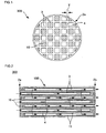
- FIG 1 is a front view schematically showing a honeycomb catalyst body according to one embodiment of the present invention.
- FIG 2 is a cross-sectional view of the honeycomb structure shown in FIG 1 along the cell extension direction.
- FIG 3 is an enlarged cross-sectional view of part (i.e., the surface of the partition wall) of the honeycomb structure shown in FIG 2 .
- a honeycomb catalyst body 300 shown in FIG. 1 includes a honeycomb structure 100 that includes a porous partition wall 4 that has a number of pores 25 (see FIG 3 ) and is disposed to form a plurality of cells 3 that extend between two end faces 2a and 2b of the honeycomb structure, and a plurality of plugging sections 10 that are disposed to plug the cells 3 on either of the end faces 2a and 2b, and a catalyst layer 15 that is supported on the surface of the partition wall 4 and contains a catalyst.
- the honeycomb catalyst body 300 shown in FIG 1 is a wall-flow filter that exhibits a low pressure loss and a high particulate matter collection efficiency.
- the permeability of the partition wall is preferably 1.0 ⁇ 10- 12 to 6.0 ⁇ 10 -12 m 2 , and more preferably 1.5 ⁇ 10 -12 to 4.0 ⁇ 10 -12 m 2 . If the permeability of the partition wall is less than 1.0 ⁇ 10 -12 m 2 , the pressure loss may increase. If the permeability of the partition wall is more than 6.0 ⁇ 10 -12 m 2 , the PM collection efficiency may decrease.
- hydroaulic diameter of cells refers to a value calculated by "4 x (cross-sectional area) / (circumferential length)".
- cross-sectional area used in the above expression refers to the cell open area in a cross section perpendicular to the cell extension direction
- circumferential length used in the above expression refers to the length of the closed line that forms the cell in a cross section perpendicular to the cell extension direction.
- permeability refers to a value calculated by the following expression (I).
- the permeability is an index that indicates the flow resistance when a given gas passes through a specimen (partition wall).
- C indicates the permeability (m 2 )
- F indicates the gas flow rate (cm 3 /s)
- T indicates the thickness (cm) of the specimen
- V indicates the gas viscosity (dynes ⁇ sec/cm 2 )
- D indicates the diameter (cm) of the specimen
- P indicates the gas pressure (PSI).
- 13.839 PSI equals 1 atm
- 68947.6 dynes ⁇ sec/cm 2 equals 1 PSI.
- the honeycomb catalyst body according to the present invention preferably has a thermal expansion coefficient of 1.0 ⁇ 10 -6 /°C or less measured at 40 to 800°C in the cell extension direction, more preferably 0.8x 10 -6 /°C or less, and particularly preferably 0.5 ⁇ 10 -6 /°C or less. If the thermal expansion coefficient is more than 1.0 ⁇ 10 -6 /°C, a thermal stress may occur during use at a high temperature so that breakage may occur.
- the term "thermal expansion coefficient" used herein refers to a value measured by push-rod dilatometry.
- the cross-sectional shape of the honeycomb catalyst body along the direction perpendicular to the cell extension direction correspond to the inner shape of an exhaust system in which the honeycomb catalyst body is installed.
- Specific examples of the cross-sectional shape of the honeycomb catalyst body include a circle, an ellipse, an oval, a trapezoid, a triangle, a quadrangle, a hexagon, an asymmetric shape, and the like. Among these, a circle, an ellipse, or an oval is preferable.
- Examples of the cross-sectional shape of the cell along the direction perpendicular to the cell extension direction include a circle, an ellipse, an oval, a trapezoid, a triangle, a quadrangle, a hexagon, an octagon, an asymmetric shape, and the like. Among these, a circle, a hexagon, or an octagon is preferable. It is preferable that the cells that are plugged on the inlet side (i.e., the cells that are open on the outlet side) be smaller in size (open area) than the cells that are plugged on the outlet side (i.e., the cells that are open on the inlet side).
- the honeycomb catalyst body according to the present invention may be used as a purification apparatus that can replace a known purification apparatus that supports a catalyst (e.g., three-way catalyst).
- a catalyst e.g., three-way catalyst
- the honeycomb structure includes a porous partition wall that has a number of pores and is disposed to form a plurality of cells that extend between two end faces of the honeycomb structure, and a plurality of plugging sections that are disposed to plug the plurality of cells on either of the end faces or inside the plurality of cells.
- a honeycomb catalyst body that shows a low pressure loss and exhibits a high exhaust gas particulate matter (PM) collection efficiency can be obtained by utilizing the honeycomb structure according to the present invention.
- the honeycomb structure is preferably formed of a material that contains at least one ceramic selected from the group consisting of cordierite, aluminum titanate, silicon carbide, sialon, mullite, silicon nitride, zirconium phosphate, zirconia, titania, alumina, and silica.
- a honeycomb structure formed of such a material exhibits high heat resistance to maintain its function even when exposed to high-temperature exhaust gas.
- the partition wall has a number of pores (i.e., porous) and is disposed to form a plurality of cells that extend between two end faces of the honeycomb structure, and satisfies the above conditions.
- a partition wall allows exhaust gas that has entered the honeycomb structure through one end face to enter the adjacent cells so that particulate matter contained in the exhaust gas can be collected. The exhaust gas can thus be purified.
- the partition wall include a partition wall body that has a number of pores, and particles that are positioned in the pores.
- a partition wall having such a configuration can be easily produced.
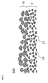
- FIG. 4 shows a honeycomb catalyst body 301 that includes a partition wall body 21 that has a number of large pores (through-holes) 27, and particles 22 that are positioned in the large pores 27.
- the partition wall 4 of the honeycomb catalyst body 301 has the pores 25 that are formed by filling the large pores 27 with the particles 22 (described later).
- FIG 4 is an enlarged cross-sectional view schematically showing part (i.e., surface) of the partition wall of the honeycomb structure according to another embodiment of the present invention.
- the thickness of the partition wall is 76.2 ⁇ m (3 mil) to 177.8 ⁇ m (7 mil), and preferably 76.2 ⁇ m (3 mil) to 127.0 ⁇ m (5 mil). If the thickness of the partition wall is less than 76.2 ⁇ m, a decrease in strength of the partition wall and a decrease in exhaust gas particulate matter (PM) collection efficiency may occur. If the thickness of the partition wall is more than 177.8 ⁇ m, the pressure loss may increase. Note that one mil equals one thousandth of an inch (about 0.025 mm). Note that the thickness of the partition wall used herein refers to a value measured using a scanning electron microscope (SEM). In FIG 1 , the thickness of the partition wall is indicated by "T".
- SEM scanning electron microscope
- the average pore size of the partition wall is 8 to 30 ⁇ m, and preferably 10 to 15 ⁇ m. If the average pore size of the partition wall is less than 8 ⁇ m, the pressure loss may increase. If the average pore size of the partition wall is more than 30 ⁇ m, the PM collection efficiency may decrease.
- the term "average pore size" used herein refers to a value measured using a mercury porosimeter.
- the porosity of the partition wall is 10 to 35%, and preferably 20 to 30%. If the porosity of the partition wall is less than 10%, the pressure loss may increase. If the porosity of the partition wall is more than 35%, the strength of the partition wall may decrease.
- porosity used herein refers to a value measured using a mercury porosimeter.
- the cell density is 12.4 cells/cm 2 (80 cpsi) to 45.0 cells/cm 2 (290 cpsi), and preferably 15.5 cells/cm 2 (100 cpsi) to 38.8 cells/cm 2 (250 cpsi). If the cell density is less than 12.4 cells/cm 2 , a decrease in strength of the partition wall, an increase in filtration flow rate, and a decrease in PM collection efficiency may occur. If the cell density is more than 45.0 cells/cm 2 , the pressure loss may increase. Note that the unit "cpsi" is an abbreviation for "cells per square inch"
- the plugging sections are disposed to plug the cells on either of the end faces or inside the cells.
- a honeycomb structure that shows a low pressure loss and exhibits a high exhaust gas particulate matter (PM) collection efficiency can be obtained by utilizing such plugging sections.
- the ceramic raw material examples include ⁇ -alumina, calcined bauxite, aluminum sulfate, aluminum chloride, aluminum hydroxide, rutile form titanium, anatase form titanium, ilmenite, electro-fused magnesium, magnesite, electro-fused spinel, kaolin, silica glass, quartz, fused silica, and the like.
- the surfactant examples include fatty acid soap, a fatty acid ester, a polyalcohol, and the like.
- the arrangement of the plugging sections is not particularly limited insofar as the plugging sections are disposed to plug the cells on either of the end faces or inside the cells.
- the plugging sections be disposed in a checkered pattern (see the plugging sections 10 of the honeycomb catalyst body 300 shown in FIGS. 1 and 2 ).
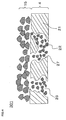
- FIG 5 is a cross-sectional view schematically showing a honeycomb catalyst body according to another embodiment of the present invention.
- FIG 5 corresponds to FIG 2 .
- the plugging sections are disposed to plug the cells inside the cells. According to this configuration, since exhaust gas passes through the partition wall at least twice, the PM collection efficiency increases. Note that the catalyst layer is omitted in FIG 5 .
- the catalyst layer is supported on the surface of the partition wall, and contains a catalyst. Therefore, exhaust gas that has entered the cells through one end face of the honeycomb catalyst body comes in contact with the catalyst supported on the surface of the partition wall so that the exhaust gas can be purified by the catalyst. The exhaust gas thus purified flows to the outside of the honeycomb catalyst body through the other end face of the honeycomb catalyst body.
- the catalyst is preferably an oxidizing catalyst that contains platinum and cerium oxide. Unburnt hydrocarbons, carbon monoxide, and PM can be effectively oxidized by utilizing the oxidizing catalyst. Since cerium oxide has an oxygen occlusion function, the oxidizing function can be maintained even when the exhaust gas has become fuel-rich.
- the catalyst be a three-way catalyst that contains at least one noble metal selected from the group consisting of platinum, rhodium, and palladium, and a promoter that contains at least one of cerium oxide and zirconium oxide. Oxidation of nitrogen oxides, reduction of hydrocarbons and carbon monoxide, and oxidation of PM can be achieved at the same time by utilizing such a three-way catalyst. Since cerium oxide has an oxygen occlusion function, the oxidizing function can be maintained even when the exhaust gas has become fuel-rich, and nitrogen oxides can be efficiently reduced even when the exhaust gas has become lean.
- the catalyst be a NOx occlusion/reduction catalyst that contains at least one of an alkali metal and an alkaline earth metal.
- a NOx occlusion/reduction catalyst nitrogen oxides can be reduced even under conditions where a three-way catalyst does not function due to a high air/fuel ratio of exhaust gas.
- the catalyst layer further contain a promoter that contains at least one compound selected from the group consisting of alumina, zirconia, and ceria, and a holding material that holds the catalyst and the promoter.
- the exhaust gas purification efficiency is improved by adding the promoter and the holding material to the catalyst layer.
- the holding material is not particularly limited insofar as the holding material can hold the catalyst and the promoter.
- the holding material include alumina, magnesium oxide, silica, cerium oxide, zirconium oxide, titania, and the like. Among these, it is preferable to use ⁇ -alumina that can stably maintain a large specific surface area. These materials may be used either individually or in combination.
- the density of the catalyst layer is preferably 80 to 400 g/L, more preferably 100 to 300 g/L, and particularly preferably 150 to 250 g/L. If the density of the catalyst layer is less than 80 g/L, the distance between the noble metal particles dispersed in the catalyst layer decreases so that the catalyst may thermally deteriorate. If the density of the catalyst layer is more than 400 g/L, the pores formed in the partition wall may be clogged so that the pressure loss may increase.
- the catalyst layer is preferably a porous layer that has a number of pores.
- exhaust gas that passes through the partition wall also passes through the catalyst layer supported on the surface of the partition wall (i.e., exhaust gas efficiently comes in contact with the catalyst contained in the catalyst layer) so that a high purification efficiency is achieved. Since it suffices that exhaust gas comes in contact with the catalyst inside the catalyst layer, the catalyst layer substantially need not be supported on the inner surface of the pores formed in the partition wall.
- the average pore size of the catalyst layer is preferably 10 ⁇ m or more, and more preferably 40 ⁇ m or more.
- the porosity of the catalyst layer is preferably 40% or more, and more preferably 50% or more. If the average pore size or the porosity is less than the above value, the flow resistance may increase to a large extent when exhaust gas passes through the catalyst layer so that the pressure loss may increase.
- the pore size of the catalyst layer used herein refers to a value measured by image analysis. Specifically, when the thickness of the catalyst layer is referred to as "t 2 ", at least twenty t 2 ⁇ t 2 areas of an SEM photograph of the cross section of the catalyst layer are observed. The maximum linear void distance is measured in each area, and half of the average value of the maximum linear distances measured for all of the areas is taken as the average pore size.
- the porosity of the catalyst layer used herein refers to a value measured by image analysis in the same manner as the pore size of the catalyst layer. Specifically, when the thickness of the catalyst layer is referred to as "t 2 ", at least five t 2 ⁇ t 2 areas of an SEM photograph of the cross section of the catalyst layer are observed. The void area ratio is measured in each area, and the average value of the void area ratios measured for all of the areas is taken as the porosity.
- the thickness of the catalyst layer is preferably 20 ⁇ m or more, more preferably 50 to 100 ⁇ m, and particularly preferably 60 to 80 ⁇ m.
- the catalyst layer since exhaust gas mainly comes in contact with the catalyst inside the catalyst layer (i.e., the purification reaction mainly occurs inside the catalyst layer), the catalyst layer must have a thickness required to provide a sufficient contact area. If the thickness of the catalyst layer is less than 20 ⁇ m, a sufficient contact area may not be obtained.
- the honeycomb catalyst body according to the present invention may be produced as follows, for example.
- a cordierite-forming raw material is provided as a material for kneaded clay.
- the cordierite-forming raw material is prepared by mixing a silica source component, a magnesia source component, an alumina source component, and the like in a cordierite crystal theoretical composition. It is preferable to use quartz or fused silica as the silica source component.
- the average particle size of the silica source component is preferably 100 to 150 ⁇ m.
- magnesia source component examples include talc, magnesite, and the like. Among these, talc is preferable.
- the content of talc in the cordierite-forming raw material is preferably 37 to 43 mass%.
- the average particle size of talc is preferably 5 to 50 ⁇ m, and more preferably 10 to 40 ⁇ m.
- the magnesia (MgO) source component may contain Fe 2 O 3 , CaO, Na 2 O, K 2 O, and the like as impurities.
- the alumina source component preferably contains at least one of aluminum oxide and aluminum hydroxide due to a low impurity content.
- the content of aluminum hydroxide in the cordierite-forming raw material is preferably 10 to 30 mass%, and the content of aluminum oxide in the cordierite-forming raw material is preferably 0 to 20 mass%.
- a material for kneaded clay (additive) added to the cordierite-forming raw material is also provided.
- At least a binder and a pore-forming material are used as additives.
- a dispersant and a surfactant may be used in addition to the binder and the pore-forming material.
- a low-melting-point reactant may be used as the pore-forming material.
- the low-melting-point reactant may be at least one metal selected from the group consisting of iron, copper, zinc, lead, aluminum, and nickel, an alloy that contains the above metal as the main component (e.g., carbon steel, cast iron, or stainless steel when using iron), or an alloy that contains two or more of the above metals as the main component.
- the low-melting-point reactant is preferably a powdery or fibrous iron alloy.
- the particle size or the fiber diameter (average diameter) of the iron alloy is preferably 10 to 200 ⁇ m.
- the low-melting-point reactant may have a spherical shape, a diamond shape, or the like. The shape of the pores can be easily controlled if the low-melting-point reactant has such a shape.
- binder examples include hydroxypropyl methyl cellulose, methyl cellulose, hydroxyethyl cellulose, carboxymethyl cellulose, polyvinyl alcohol, and the like.
- dispersant examples include dextrin, a polyalcohol, and the like.
- surfactant examples include a fatty acid soap and the like. These additives may be used either individually or in combination.
- the kneaded clay is formed into a honeycomb shape by an extrusion forming method, an injection forming method, a press forming method, or the like to obtain a honeycomb formed body. It is preferable to use the extrusion forming method since the kneaded clay can be continuously formed, and cordierite crystals can be oriented.
- the extrusion forming method may be implemented using a vacuum kneader, a ram extruder, a twin-screw continuous extruder, or the like.
- the honeycomb formed body is then dried and fired to obtain an intermediate honeycomb structure.
- the honeycomb formed body may be dried by hot-air drying, microwave drying, dielectric drying, drying under reduced pressure, vacuum drying, freeze drying, or the like. It is preferable to dry the honeycomb formed body by hot-air drying and microwave drying or dielectric drying since the entire honeycomb formed body can be dried quickly and uniformly.
- the dried honeycomb formed body is fired to obtain an intermediate honeycomb structure provided with a partition wall having pores with an average pore size of 8 to 300 ⁇ m.
- the honeycomb formed body formed using the cordierite-forming raw material is normally fired at 1410 to 1440°C for 3 to 15 hours in the air.
- the partition wall When using the low-melting-point reactant as the pore-forming material, the partition wall has large pores (average pore size: about 100 to 300 ⁇ m).
- a slurry that contains filling particles having an average particle size of 5 to 20 ⁇ m is prepared, and the pores formed in the partition wall are filled with the slurry.
- the honeycomb formed body is then dried and fired to reduce the average pore size of the pores formed in the partition wall.
- the filling particles may be formed of the same material as the material for the honeycomb structure. Specific examples of the material for the filling particles include cordierite, SiC, aluminum titanate, and the like.
- the pores may be filled with the slurry by a pressurization method, a suction method, or the like.
- the average pore size of the partition wall may be adjusted by adjusting the particle size of the filling particles.
- FIG 4 shows an example in which the partition wall body 21 in which the large pores 27 are formed is obtained using the low-melting-point reactant as the pore-forming material, and the large pores 27 formed in the partition wall body 21 are filled with the filling particles 22 to obtain the partition wall 4.
- honeycomb structure honeycomb structure body in which the cells are not plugged is thus obtained.
- a raw material for the plugging section is provided.
- the material for the plugging sections i.e., plugging slurry
- the material for the plugging sections may be the same as or different from the material for kneaded clay used for the honeycomb structure body.
- the material for the plugging section i.e., plugging slurry
- the material for the plugging section may be obtained by mixing a ceramic raw material, a surfactant, and water optionally together with a sintering aid, a pore-forming agent, and the like to prepare a slurry, and kneading the slurry using a mixer or the like.
- honeycomb structure body The cells that are not to be plugged are masked on one end face of the honeycomb structure body, and the one end face of the honeycomb structure body is immersed in the plugging slurry in a container to fill the unmasked cells with the plugging slurry.
- the honeycomb structure body is then dried and fired to obtain a honeycomb structure body (i.e., honeycomb structure) provided with the plugging sections.
- the drying/firing conditions may be the same as the drying/firing conditions for the honeycomb formed body.
- a catalyst layer material (slurry) that contains an organic pore-forming material and a catalyst is applied to the surface of the partition wall of the honeycomb structure.
- the honeycomb structure is heated to a given temperature during or after drying the catalyst layer material to oxidize and remove the organic pore-forming material to form pores in the catalyst layer.
- a honeycomb catalyst body that includes the honeycomb structure and the catalyst layer that is supported on the surface of the partition wall and contains the catalyst is thus obtained.
- the average particle size of the disaggregated particles contained in the slurry raw material be equal to or larger than the average particle size of the partition wall material. If the average particle size of the disaggregated particles contained in the slurry raw material is equal to or larger than the average particle size of the partition wall, the disaggregated particles do not easily enter the pores formed in the partition wall. Therefore, the slurry can be easily applied to the surface of the partition wall.
- the average particle size of the disaggregated particles is equal to or larger than 1/4 of the average pore size of the partition wall, the disaggregated particles are crosslinked at the entrance of the pores formed in the partition wall and do not easily enter the pores. Therefore, the slurry can be applied to the surface of the partition wall.
- organic pore-forming material starch, a resin foam, or the like may be suitably used. Resin particles that can be removed by heating at 700°C or less may be added as the pore-forming material.
- the catalyst layer material may be applied by a known method. For example, a dipping method, a suction method, or the like may be used.
- the porosity of the catalyst layer may be adjusted by adjusting the amount of pore-forming material and the like.
- the average pore size of the catalyst layer may be adjusted by adjusting the average particle size of the oxide that mainly forms the catalyst layer material, for example.
- oxide particles having an average particle size of 40 ⁇ m are used for the catalyst layer material.
- the catalyst layer material (slurry) may be applied to the surface of the partition wall of the honeycomb structure by a suction method or the like.
- the cell open area (cross-sectional area) in a cross section perpendicular to the cell extension direction, and the length (circumferential length) of the closed line forming the cell in a cross section perpendicular to the cell extension direction were measured for a plurality of (20) cells.
- the average value of the values calculated by "4 ⁇ (cross-sectional area) / (circumferential length)" was taken as the hydraulic diameter (m) of the cells.
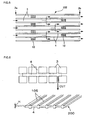
- the permeability was calculated as follows. As shown in FIG 6 , a honeycomb catalyst body 300 was cut into a specimen 200 so that the part (rib 105) of the partition wall 4 remained to have a rib height H of 0.2 mm.
- the specimen 200 may have a rectangular shape or a disc-like shape. Air at room temperature was passed through the specimen 200, and the permeability was calculated by the following expression (1).
- FIG 6 is a schematic view illustrative of the specimen used to measure the permeability.
- a fluid seal e.g., grease
- the permeability was measured at an air flow rate that was adjusted so that the calculated flow rate through the partition wall was 0.1 to 1 cm/sec.
- C indicates the permeability (m 2 )
- F indicates the gas flow rate (cm 3 /s)
- T indicates the thickness (cm) of the specimen
- V indicates the gas viscosity (dynes ⁇ sec/cm 2 )
- D indicates the diameter (cm) of the specimen
- P indicates the gas pressure (PSI).
- 13.839 PSI equals 1 atm
- 68947.6 dynes ⁇ sec/cm 2 equals I PSI.
- the permeability was measured using a "Capillary Flow Porometer 1100AEX" (manufactured by Porous Materials, Inc.).
- the permeability (m 2 ) of the honeycomb structure was measured in the same manner as described above.
- One end face of the honeycomb catalyst body was observed using a scanning electron microscope (SEM). The thickness was measured for an arbitrarily selected ten areas of the partition wall, and the average thickness was taken as the thickness of the partition wall.
- the pore size (pore size calculated from the pressure when the cumulative mercury volume injected into a porous substrate reached 50% of the total pore volume of the porous substrate) was measured using a mercury porosimeter (mercury intrusion method).
- a mercury porosimeter mercury intrusion method
- an "Auto Pore III 9405" manufactured by Micrometrics was used.
- the porosity was measured using a mercury porosimeter (mercury intrusion method) in the same manner as the average pore size.
- One end face of the honeycomb catalyst body was observed using a scanning electron microscope (SEM). The number of cells present in an arbitrarily selected area was measured to calculate the cell density.
- the ratio of the total open area of the cells to the sum of the cross-sectional area of the partition wall and the total open area of the cells in the cross section perpendicular to the cell extension direction was calculated, and taken as the cell open frontal area.
- the thermal expansion coefficient was measured by push-rod dilatometry.
- Air was circulated through the honeycomb catalyst body at room temperature at a flow rate of 0.5 m 3 /min to measure the pressure loss.
- the pressure loss (reference pressure loss) of a comparative honeycomb catalyst body having an identical shape, an identical cell density, and an identical partition wall thickness was measured, and the ratio (pressure drop increase rate (%)) with respect to the reference pressure loss was calculated.
- a case where the pressure drop increase rate was 20% or more was evaluated as "Bad", and a case where the pressure drop increase rate was less than 20% was evaluated as "Good”.
- Exhaust gas discharged from a diesel burner was introduced into the honeycomb catalyst body at a particulate matter (PM) concentration of 1 mg/m 3 , a temperature of 200°C, and a flow rate of 2.4 Nm 3 /min, and the number of PM (PM particle count) was measured on the upstream side (before the exhaust gas was introduced into the honeycomb catalyst body) and the downstream side (after the exhaust gas was discharged from the honeycomb catalyst body).
- the PM collection efficiency was calculated by "((upstream-side PM particle count) - (downstream-side PM particle count)) / (upstream-side PM particle count) ⁇ 100".
- the PM particle count was measured using a "Scanning Mobility Particle Sizer (SMPS)" (manufactured by TSI). A case where the PM collection efficiency was 80% or more was evaluated as “Good”, and a case where the PM collection efficiency was less than 80% was evaluated as "Bad”.
- SMPS Sccanning Mobility Particle Sizer
- a hydrostatic pressure was applied to the outer circumferential surface of the honeycomb structure covered with rubber, and the pressure when the honeycomb structure broke was measured.
- a case where the honeycomb structure broke at a pressure of less than 2.0 MPa was evaluated as "Bad”, and a case where the honeycomb structure broke at a pressure of 2.0 MPa or more was evaluated as "Good”.
- the honeycomb structure was installed in the exhaust system of an automobile equipped with a direct-injection gasoline engine (displacement: 2.0 L) at a position under the floor.
- the automobile was operated on a chassis dynamo five times in the European NEDC mode. A case where the pressure loss increase rate was less than 1.1% was evaluated as “Good”, and a case where the pressure loss increase rate was 1.1 % or more was evaluated as "Bad”.
- the honeycomb structure was installed in the exhaust system of an automobile equipped with a direct-injection gasoline engine (displacement: 2.0 L) at a position under the floor.
- the automobile was operated on a chassis dynamo in the European NEDC mode to measure the emissions of carbon monoxide, unburnt hydrocarbons, and nitrogen oxides.
- the emissions of carbon monoxide, unburnt hydrocarbons, and nitrogen oxides were also measured using a flow-through honeycomb catalyst body (partition wall thickness: 100 ⁇ m, cell density: 93 cells/cm 2 ) supporting an identical amount of an identical catalyst.
- the measured emission values were then compared. A case where the emissions were larger than those of the comparative honeycomb catalyst body was evaluated as "Bad", and a case where the emissions were smaller than those of the comparative honeycomb catalyst body was evaluated as "Good”.
- a raw material was prepared as shown in Table 1 (average particle size and mixing ratio). Specifically, 39.7 mass% of talc (average particle size: 22 ⁇ m), 51.2 mass% of kaolin (average particle size: 7 ⁇ m), 5.5 mass% of aluminum oxide (average particle size: 6 ⁇ m), and 12.7 mass% of aluminum hydroxide (average particle size: I ⁇ m) were mixed to prepare a material for kneaded clay.
- kneaded clay 100 parts by mass of the material for kneaded clay, 8 parts by mass of hydroxypropyl methyl cellulose (binder), 0.1 parts by mass of potassium laurate soap (dispersant), and 35 parts by mass of water were mixed and kneaded to obtain a kneaded clay having plasticity.
- the kneaded clay was formed into a cylindrical shape using a vacuum deairing machine, and formed into a honeycomb shape having a given partition wall thickness and a given cell density using an extruder to obtain a honeycomb formed body.
- the honeycomb formed body was dielectric-dried, hot-air-dried, and fired at 1420°C for 10 hours to obtain an intermediate honeycomb structure provided with a partition wall having pores with an average pore size of 8 to 30 ⁇ m.
- honeycomb structure body The end faces of the honeycomb structure body were plugged alternately (in a checkered pattern) using the same material (plugging slurry) as the material for kneaded clay , and the intermediate honeycomb structure was fired at 1420°C for four hours to obtain a honeycomb structure.
- the honeycomb structure had a diameter of 105 mm, a length of 114 mm, and a plugging depth of 5 mm. The honeycomb structure was subjected to the above measurements and evaluations.
- the honeycomb structure of this reference example had a partition wall thickness of 81.3 ⁇ m (3.2 mil), a cell density of 43.4 cells/cm 2 (280 cpsi), a cell hydraulic diameter of 0.00144 m, a cell open frontal area of 89.6%, a partition wall average pore size of 13 ⁇ m, a partition wall porosity of 27%, a partition wall permeability of 1.56 ⁇ 10 -12 , and a value "(hydraulic diameter of cells) 2 / (permeability)" of 1.32 ⁇ 10 6 .
- the pressure loss evaluation result was "Good”
- the PM collection efficiency evaluation result was "Good”
- the partition wall strength evaluation result was “Good”
- the partition wall clogging evaluation result was also "Good”.
- a kneaded clay was prepared in the same manner as in Reference Example 1, except that the mixing ratio and the raw material particle size were changed as shown in Table 1.
- a honeycomb structure shown in Table 2 was obtained in the same manner as in Reference Example 1. The measurement and evaluation results for the resulting honeycomb structure are shown in Tables 2 and 3.
- talc As shown in Table 1, 40 mass% of talc (average particle size: 32 ⁇ m) (talc having an average particle size of 35 ⁇ m was used in Reference Example 10), 19 mass% of kaolin (average particle size: 35 ⁇ m), 12 mass% of quartz (average particle size: 116 ⁇ m), 14 mass% of aluminum oxide (average particle size: 6 ⁇ m), 15 mass% of aluminum hydroxide (average particle size: 3 ⁇ m), and 20 mass% of iron powder (pore-forming material) (average particle size: 30 ⁇ m) were mixed to prepare a material for kneaded clay.
- kaolin average particle size: 35 ⁇ m
- quartz average particle size: 116 ⁇ m
- aluminum oxide average particle size: 6 ⁇ m
- 15 mass% of aluminum hydroxide average particle size: 3 ⁇ m
- iron powder pore-forming material
- the material for kneaded clay was processed in the same manner as in Reference Example 1 to obtain an intermediate honeycomb structure provided with a partition wall having pores with an average pore size of 100 to 300 ⁇ m.
- honeycomb structure body A honeycomb structure containing cordierite particles having an average particle size of 20 ⁇ m was prepared. The pores formed in the partition wall of the intermediate honeycomb structure were filled with the slurry. The intermediate honeycomb structure was then dried and fired under the same conditions as those for the honeycomb formed body to obtain a honeycomb structure (i.e., honeycomb structure body) in which the cells were not plugged. The measurement and evaluation results for the resulting honeycomb structure are shown in Tables 2 and 3.
- a honeycomb structure was obtained in the same manner as in Reference Example 1, except that the conditions were changed as shown in Table 4.
- a catalyst layer material (catalyst slurry) containing an oxidizing catalyst (platinum and alumina) and an organic pore-forming material (polymer particles) was applied to and supported on the surface of the partition wall of the honeycomb structure by a suction method so that the density was 200 g/L.
- the honeycomb structure was dried at a given temperature to oxidize and remove the organic pore-forming material.
- a honeycomb catalyst body including a porous catalyst layer supported on the surface of the partition wall of the honeycomb structure was thus obtained.
- the honeycomb catalyst body of this example had a partition wall thickness of 81.3 ⁇ m (3.2 mil), a cell density of 43.4 cells/cm 2 (280 cpsi), a cell hydraulic diameter of 0.00144 m, a cell open frontal area of 89.6%, a partition wall average pore size of 13 ⁇ m, a partition wall porosity of 27%, a partition wall permeability of 1.25x,o-l 2, and a value "(hydraulic diameter of cells) 2 / (permeability)" of 1.65 ⁇ 10 6 .
- the pressure loss evaluation result was "Good”
- the PM collection efficiency evaluation result was "Good”
- the partition wall strength evaluation result was “Good”
- the partition wall clogging evaluation result was “Good”
- the exhaust gas purification performance evaluation result was also "Good”.
- honeycomb catalyst bodies of Examples 2 to 16 and Comparative Examples 1 to 8 were obtained in the same manner as in Example 1, except that the conditions were changed as shown in Table 4.
- the honeycomb catalyst bodies were evaluated in the same manner as described above. The measurement results are shown in Table 5, and the evaluation results are shown in Table 6.
- Example 1 39.7 (22 ⁇ m) 51.2 (7 ⁇ m) 0 0 5.5 (6 ⁇ m) 12.7 (1 ⁇ m) 0 0
- Example 2 39.7 (22 ⁇ m) 51.2 (7 ⁇ m) 0 0 5.5 (6 ⁇ m) 12.7 (1 ⁇ m) 0 0
- Example 3 39.7 (22 ⁇ m) 51.2 (7 ⁇ m) 0 0 5.5 (6 ⁇ m) 12.7 ( 1 ⁇ m) 0 0
- Example 4 39.7 (22 ⁇ m) 51.2 (7 ⁇ m) 0 0 5.5 (6 ⁇ m) 12.7 (1 ⁇ m) 0 0
- Example 5 40 32
- Example 12 39.7 (22 ⁇ m) 51.2 (7 ⁇ m) 0 0 18.2 (6 ⁇ m) 0 0 0
- Example 13 39.7 (22 ⁇ m) 51.2 (7 ⁇ m) 0 0 18.2 (6 ⁇ m) 0 0 0
- Example 14 39.7 (22 ⁇ m) 51.2 (7 ⁇ m) 0 0 18.2 (6 ⁇ m) 0 0 0
- Example 15 39.4 (22 ⁇ m) 21.5 (7 ⁇ m) 0 10 (30 ⁇ m) 29.0 (6 ⁇ 1 m) 0 0 0
- Example 16 39.6 (32 ⁇ m) 31.8 (7 ⁇ m) 0 5 (30 ⁇ m) 7.1 (6 ⁇ m) 16.5 (1 ⁇ m) 0 0
- Comparative Example 1 39.7 (22 ⁇ m) 51.2 (7 ⁇ m) 0 0 18.2 (6 ⁇ m) 0 0 0
- Comparative Example 2 39.7 (50 ⁇ m) 5
- the honeycomb catalyst bodies of Examples I to 16 exhibited a sufficient partition wall strength, a low pressure loss, rarely showed clogging due to soot, and exhibited a sufficiently high PM collection efficiency and a high exhaust gas purification efficiency as compared with the honeycomb structures of Comparative Examples 1 to 8.
- honeycomb catalyst body according to the present invention may be suitably utilized as a filter that removes particulate matter contained in exhaust gas discharged from an internal combustion engine (e.g., automobile engine, construction machine engine, or stationary industrial engine), a combustion apparatus, and the like.
- an internal combustion engine e.g., automobile engine, construction machine engine, or stationary industrial engine
Claims (10)
- Wabenkatalysatorkörper (300), der Folgendes umfasst:eine Wabenstruktur (100), die Folgendes umfasst: eine poröse Trennwand (4), die eine Reihe von Poren (25) aufweist und angeordnet ist, um eine Vielzahl an Zellen (3) zu bilden, die sich zwischen zwei Endflächen (2a, 2b) der Wabenstruktur (100) erstrecken und eine Vielzahl an Verschlussabschnitten (10), die angeordnet sind, um die Vielzahl an Zellen (3) an einer der Endflächen (2a, 2b) oder im Inneren der Vielzahl an Zellen (3) zu verschließen; undeine Katalysatorschicht (15), die auf der Oberfläche der Trennwand (4) getragen wird und einen Katalysator enthält,wobei die Trennwand (4) eine Dicke von 76,2 bis 177,8 µm, eine mittlere Porengröße von 8 bis 30 µm und eine Porosität von 10 bis 35 % aufweist und die Wabenstruktur (100) eine Zelldichte von 12,4 bis 45,0 Zellen/cm2 aufweist, und wobeider Anteil der Gesamtöffnungsfläche der Vielzahl an Zellen (3) an der Summe der Querschnittsfläche der Trennwand (4) und der Gesamtöffnungsfläche der Vielzahl an Zellen (3) in einem Querschnitt im rechten Winkel auf die Zellerstreckungsrichtung 83 bis 90 % beträgt.
- Wabenkatalysatorkörper (300) nach Anspruch 1, worin die Trennwand (4) eine Permeabilität von 1 x10-12 bis 6x10-12 m2 aufweist.
- Wabenkatalysatorkörper (300) nach Anspruch 1 oder 2, worin für den hydraulischen Durchmesser (m) der Zellen (3) und die Permeabilität (m2) der Trennwand (4) folgendes Verhältnis gilt: (hydraulischer Durchmesser der Zellen)2/(Permeabilität) = 1,0x10⁵ bis 4,5x10⁶.
- Wabenkatalysatorkörper (300) nach einem der Ansprüche 1 bis 3, wobei die Wabenstruktur (100) aus einem Material ausgebildet ist, das zumindest ein aus folgender Gruppe ausgewähltes Keramikmaterial enthält: Cordierit, Aluminiumtitanat, Siliciumcarbid, Sialon, Mullit, Siliciumnitrid, Zirconiumphosphat, Zirconiumdioxid, Titanoxid, Aluminiumoxid und Siliciumdioxid.
- Wabenkatalysatorkörper (300) nach einem der Ansprüche 1 bis 4, wobei der Wabenkatalysatorkörper bei 40 bis 800 °C in Zellerstreckungsrichtung einen Wärmeausdehnungskoeffizienten von 1,0x10⁻⁶/°C oder weniger aufweist.
- Wabenkatalysatorkörper (300) nach einem der Ansprüche 1 bis 5, worin der Katalysator ein oxidierender Katalysator ist, der Platin und Ceroxid enthält.
- Wabenkatalysatorkörper (300) nach einem der Ansprüche 1 bis 5, worin der Katalysator ein Dreiweg-Katalysator ist, der zumindest ein aus der aus Platin, Rhodium und Palladium bestehenden Gruppe ausgewähltes Edelmetall und einen Promotor enthält, der zumindest eine Substanz ausgewählt aus Ceroxid und Zirconiumoxid enthält.
- Wabenkatalysatorkörper (300) nach einem der Ansprüche 1 bis 5, worin der Katalysator ein NOx-Einschluss-/Reduktionskatalysator ist, der zumindest eine Substanz ausgewählt aus einem Alkalimetall und einem Erdalkalimetall enthält.
- Wabenkatalysatorkörper (300) nach einem der Ansprüche 1 bis 8, worin die Katalysatorschicht (15) ferner einen Promotor enthält, der zumindest eine aus der aus folgenden bestehenden Gruppe ausgewählte Verbindung enthält: Aluminiumoxid, Zirconiumdioxid und Ceroxid, sowie ein Haltematerial, das den Katalysator und den Promotor hält.
- Wabenkatalysatorkörper (300) nach einem der Ansprüche 1 bis 9, worin die Katalysatorschicht (15) eine Dichte von 80 bis 400 g/l aufweist.
Applications Claiming Priority (1)
| Application Number | Priority Date | Filing Date | Title |
|---|---|---|---|
| JP2009072372A JP5064432B2 (ja) | 2009-03-24 | 2009-03-24 | ハニカム触媒体 |
Publications (2)
| Publication Number | Publication Date |
|---|---|
| EP2236188A1 EP2236188A1 (de) | 2010-10-06 |
| EP2236188B1 true EP2236188B1 (de) | 2012-06-20 |
Family
ID=42543302
Family Applications (1)
| Application Number | Title | Priority Date | Filing Date |
|---|---|---|---|
| EP10250480A Active EP2236188B1 (de) | 2009-03-24 | 2010-03-15 | Wabenförmiger Katalysatorkörper |
Country Status (2)
| Country | Link |
|---|---|
| EP (1) | EP2236188B1 (de) |
| JP (1) | JP5064432B2 (de) |
Families Citing this family (15)
| Publication number | Priority date | Publication date | Assignee | Title |
|---|---|---|---|---|
| JP4991778B2 (ja) * | 2009-03-24 | 2012-08-01 | 日本碍子株式会社 | ハニカム構造体 |
| JP5981854B2 (ja) | 2011-09-29 | 2016-08-31 | 日本碍子株式会社 | ハニカムフィルタ、及びその製造方法 |
| WO2013175552A1 (ja) | 2012-05-21 | 2013-11-28 | イビデン株式会社 | ハニカムフィルタ、排ガス浄化装置、及び、排ガス浄化方法 |
| JP2016507684A (ja) * | 2012-11-30 | 2016-03-10 | ダウ グローバル テクノロジーズ エルエルシー | ハニカムフィルタによるガソリン直噴射エンジン排ガスの濾過 |
| JP6502133B2 (ja) | 2014-03-28 | 2019-04-17 | 日本碍子株式会社 | 多孔質体、ハニカムフィルタ、多孔質体の製造方法、及びハニカムフィルタの製造方法 |
| DE102016102506A1 (de) * | 2015-12-22 | 2017-06-22 | Elringklinger Ag | Packung und Kolonne umfassend eine oder mehrere Packungen |
| DE102017106374A1 (de) * | 2016-04-01 | 2017-10-05 | Johnson Matthey Public Limited Company | Abgasreinigungsfilter |
| JP2018143956A (ja) | 2017-03-06 | 2018-09-20 | イビデン株式会社 | ハニカムフィルタ |
| JP6637008B2 (ja) * | 2017-09-29 | 2020-01-29 | 株式会社キャタラー | 排ガス浄化用触媒 |
| BR112020017344A2 (pt) * | 2018-02-26 | 2020-12-15 | Basf Corporation | Catalisadores, catalisador de tratamento posterior de gases, processo de preparação do catalisador, métodos de tratamento e sistema de purificação |
| DE112018007753T5 (de) | 2018-06-20 | 2021-03-04 | Ngk Insulators, Ltd. | Poröser Verbundwerkstoff |
| JP2020142165A (ja) * | 2019-03-04 | 2020-09-10 | 東京濾器株式会社 | フィルタ |
| JP7230671B2 (ja) * | 2019-04-26 | 2023-03-01 | 株式会社デンソー | 排ガス浄化フィルタ |
| CN115023538B (zh) * | 2020-02-07 | 2023-09-08 | 日本碍子株式会社 | 蜂窝结构体及尾气净化装置 |
| JP2022123542A (ja) * | 2021-02-12 | 2022-08-24 | 日本碍子株式会社 | 目封止ハニカム構造体 |
Family Cites Families (9)
| Publication number | Priority date | Publication date | Assignee | Title |
|---|---|---|---|---|
| JP3756721B2 (ja) | 2000-03-24 | 2006-03-15 | 日本碍子株式会社 | 排ガス浄化用フィルター |
| JP4640903B2 (ja) * | 2001-07-13 | 2011-03-02 | 日本碍子株式会社 | ハニカム構造体、及びその製造方法 |
| JP5189236B2 (ja) | 2001-07-25 | 2013-04-24 | 日本碍子株式会社 | 排ガス浄化用ハニカム構造体及び排ガス浄化用ハニカム触媒体 |
| CN1699921A (zh) * | 2002-03-27 | 2005-11-23 | 日本碍子株式会社 | 蜂窝结构体的外周畸变度的测定方法 |
| KR100820619B1 (ko) * | 2004-12-28 | 2008-04-08 | 이비덴 가부시키가이샤 | 필터 및 필터 집합체 |
| JP5026674B2 (ja) * | 2005-03-04 | 2012-09-12 | 日本碍子株式会社 | ハニカム構造体 |
| FR2893861B1 (fr) * | 2005-11-30 | 2008-01-04 | Saint Gobain Ct Recherches | Structure de filtration d'un gaz a base de sic de porosite de surface de paroi controlee |
| US8298311B2 (en) * | 2006-11-15 | 2012-10-30 | Corning Incorporated | Filters with controlled submicron porosity |
| JP2008126192A (ja) * | 2006-11-24 | 2008-06-05 | Ngk Insulators Ltd | ハニカム担体 |
-
2009
- 2009-03-24 JP JP2009072372A patent/JP5064432B2/ja active Active
-
2010
- 2010-03-15 EP EP10250480A patent/EP2236188B1/de active Active
Also Published As
| Publication number | Publication date |
|---|---|
| EP2236188A1 (de) | 2010-10-06 |
| JP2010221154A (ja) | 2010-10-07 |
| JP5064432B2 (ja) | 2012-10-31 |
Similar Documents
| Publication | Publication Date | Title |
|---|---|---|
| EP2236188B1 (de) | Wabenförmiger Katalysatorkörper | |
| EP2239037B1 (de) | Verfahren zur Herstellung einer Wabenstruktur und Verfahren zur Herstellung eines wabenförmigen Katalysatorkörpers | |
| EP2236189B1 (de) | Wabenstruktur | |
| EP2339135B1 (de) | Substrat mit Oberflächenfilterschicht und katalysatorbeschichtetes Substrat mit Oberflächenfilterschicht | |
| US8283019B2 (en) | Honeycomb structured body | |
| JP5313658B2 (ja) | セラミック構造体及びその製造方法 | |
| US8039415B2 (en) | Honeycomb structure | |
| EP2042224B1 (de) | Wabenfilter | |
| US7731774B2 (en) | Honeycomb structured body | |
| EP2216085A1 (de) | Katalytischer Wabenartikel | |
| JP5270879B2 (ja) | ハニカム構造体 | |
| EP2364764B1 (de) | Abgasreinigungsvorrichtung und Abgasreinigungsverfahren | |
| EP2937143A1 (de) | Keramikwabenstruktur und verfahren zur herstellung davon | |
| EP2108439A1 (de) | Katalysierter Diesel-Partikelfilter und Herstellungsverfahren dafür | |
| EP2108448B1 (de) | Wabenkatalysatorkörper | |
| JP6074306B2 (ja) | ハニカム構造体 | |
| US11071937B2 (en) | Ceramic porous body and method for producing the same, and dust collecting filter | |
| JP2014198316A (ja) | ハニカム構造体 |
Legal Events
| Date | Code | Title | Description |
|---|---|---|---|
| PUAI | Public reference made under article 153(3) epc to a published international application that has entered the european phase |
Free format text: ORIGINAL CODE: 0009012 |
|
| AK | Designated contracting states |
Kind code of ref document: A1 Designated state(s): AT BE BG CH CY CZ DE DK EE ES FI FR GB GR HR HU IE IS IT LI LT LU LV MC MK MT NL NO PL PT RO SE SI SK SM TR |
|
| AX | Request for extension of the european patent |
Extension state: AL BA ME RS |
|
| 17P | Request for examination filed |
Effective date: 20110316 |
|
| GRAP | Despatch of communication of intention to grant a patent |
Free format text: ORIGINAL CODE: EPIDOSNIGR1 |
|
| RIC1 | Information provided on ipc code assigned before grant |
Ipc: B01D 46/24 20060101AFI20111229BHEP |
|
| GRAS | Grant fee paid |
Free format text: ORIGINAL CODE: EPIDOSNIGR3 |
|
| GRAA | (expected) grant |
Free format text: ORIGINAL CODE: 0009210 |
|
| AK | Designated contracting states |
Kind code of ref document: B1 Designated state(s): AT BE BG CH CY CZ DE DK EE ES FI FR GB GR HR HU IE IS IT LI LT LU LV MC MK MT NL NO PL PT RO SE SI SK SM TR |
|
| REG | Reference to a national code |
Ref country code: GB Ref legal event code: FG4D |
|
| REG | Reference to a national code |
Ref country code: CH Ref legal event code: EP |
|
| REG | Reference to a national code |
Ref country code: AT Ref legal event code: REF Ref document number: 562683 Country of ref document: AT Kind code of ref document: T Effective date: 20120715 |
|
| REG | Reference to a national code |
Ref country code: IE Ref legal event code: FG4D |
|
| REG | Reference to a national code |
Ref country code: DE Ref legal event code: R096 Ref document number: 602010001965 Country of ref document: DE Effective date: 20120816 |
|
| PG25 | Lapsed in a contracting state [announced via postgrant information from national office to epo] |
Ref country code: LT Free format text: LAPSE BECAUSE OF FAILURE TO SUBMIT A TRANSLATION OF THE DESCRIPTION OR TO PAY THE FEE WITHIN THE PRESCRIBED TIME-LIMIT Effective date: 20120620 Ref country code: NO Free format text: LAPSE BECAUSE OF FAILURE TO SUBMIT A TRANSLATION OF THE DESCRIPTION OR TO PAY THE FEE WITHIN THE PRESCRIBED TIME-LIMIT Effective date: 20120920 Ref country code: FI Free format text: LAPSE BECAUSE OF FAILURE TO SUBMIT A TRANSLATION OF THE DESCRIPTION OR TO PAY THE FEE WITHIN THE PRESCRIBED TIME-LIMIT Effective date: 20120620 Ref country code: SE Free format text: LAPSE BECAUSE OF FAILURE TO SUBMIT A TRANSLATION OF THE DESCRIPTION OR TO PAY THE FEE WITHIN THE PRESCRIBED TIME-LIMIT Effective date: 20120620 |
|
| REG | Reference to a national code |
Ref country code: NL Ref legal event code: VDEP Effective date: 20120620 |
|
| REG | Reference to a national code |
Ref country code: AT Ref legal event code: MK05 Ref document number: 562683 Country of ref document: AT Kind code of ref document: T Effective date: 20120620 |
|
| REG | Reference to a national code |
Ref country code: LT Ref legal event code: MG4D Effective date: 20120620 |
|
| PG25 | Lapsed in a contracting state [announced via postgrant information from national office to epo] |
Ref country code: GR Free format text: LAPSE BECAUSE OF FAILURE TO SUBMIT A TRANSLATION OF THE DESCRIPTION OR TO PAY THE FEE WITHIN THE PRESCRIBED TIME-LIMIT Effective date: 20120921 Ref country code: HR Free format text: LAPSE BECAUSE OF FAILURE TO SUBMIT A TRANSLATION OF THE DESCRIPTION OR TO PAY THE FEE WITHIN THE PRESCRIBED TIME-LIMIT Effective date: 20120620 Ref country code: LV Free format text: LAPSE BECAUSE OF FAILURE TO SUBMIT A TRANSLATION OF THE DESCRIPTION OR TO PAY THE FEE WITHIN THE PRESCRIBED TIME-LIMIT Effective date: 20120620 Ref country code: SI Free format text: LAPSE BECAUSE OF FAILURE TO SUBMIT A TRANSLATION OF THE DESCRIPTION OR TO PAY THE FEE WITHIN THE PRESCRIBED TIME-LIMIT Effective date: 20120620 |
|
| PG25 | Lapsed in a contracting state [announced via postgrant information from national office to epo] |
Ref country code: SK Free format text: LAPSE BECAUSE OF FAILURE TO SUBMIT A TRANSLATION OF THE DESCRIPTION OR TO PAY THE FEE WITHIN THE PRESCRIBED TIME-LIMIT Effective date: 20120620 Ref country code: CY Free format text: LAPSE BECAUSE OF FAILURE TO SUBMIT A TRANSLATION OF THE DESCRIPTION OR TO PAY THE FEE WITHIN THE PRESCRIBED TIME-LIMIT Effective date: 20120620 Ref country code: AT Free format text: LAPSE BECAUSE OF FAILURE TO SUBMIT A TRANSLATION OF THE DESCRIPTION OR TO PAY THE FEE WITHIN THE PRESCRIBED TIME-LIMIT Effective date: 20120620 Ref country code: BE Free format text: LAPSE BECAUSE OF FAILURE TO SUBMIT A TRANSLATION OF THE DESCRIPTION OR TO PAY THE FEE WITHIN THE PRESCRIBED TIME-LIMIT Effective date: 20120620 Ref country code: IS Free format text: LAPSE BECAUSE OF FAILURE TO SUBMIT A TRANSLATION OF THE DESCRIPTION OR TO PAY THE FEE WITHIN THE PRESCRIBED TIME-LIMIT Effective date: 20121020 Ref country code: RO Free format text: LAPSE BECAUSE OF FAILURE TO SUBMIT A TRANSLATION OF THE DESCRIPTION OR TO PAY THE FEE WITHIN THE PRESCRIBED TIME-LIMIT Effective date: 20120620 Ref country code: EE Free format text: LAPSE BECAUSE OF FAILURE TO SUBMIT A TRANSLATION OF THE DESCRIPTION OR TO PAY THE FEE WITHIN THE PRESCRIBED TIME-LIMIT Effective date: 20120620 Ref country code: CZ Free format text: LAPSE BECAUSE OF FAILURE TO SUBMIT A TRANSLATION OF THE DESCRIPTION OR TO PAY THE FEE WITHIN THE PRESCRIBED TIME-LIMIT Effective date: 20120620 |
|
| PG25 | Lapsed in a contracting state [announced via postgrant information from national office to epo] |
Ref country code: PT Free format text: LAPSE BECAUSE OF FAILURE TO SUBMIT A TRANSLATION OF THE DESCRIPTION OR TO PAY THE FEE WITHIN THE PRESCRIBED TIME-LIMIT Effective date: 20121022 Ref country code: PL Free format text: LAPSE BECAUSE OF FAILURE TO SUBMIT A TRANSLATION OF THE DESCRIPTION OR TO PAY THE FEE WITHIN THE PRESCRIBED TIME-LIMIT Effective date: 20120620 Ref country code: IT Free format text: LAPSE BECAUSE OF FAILURE TO SUBMIT A TRANSLATION OF THE DESCRIPTION OR TO PAY THE FEE WITHIN THE PRESCRIBED TIME-LIMIT Effective date: 20120620 |
|
| PG25 | Lapsed in a contracting state [announced via postgrant information from national office to epo] |
Ref country code: NL Free format text: LAPSE BECAUSE OF FAILURE TO SUBMIT A TRANSLATION OF THE DESCRIPTION OR TO PAY THE FEE WITHIN THE PRESCRIBED TIME-LIMIT Effective date: 20120620 |
|
| PLBE | No opposition filed within time limit |
Free format text: ORIGINAL CODE: 0009261 |
|
| STAA | Information on the status of an ep patent application or granted ep patent |
Free format text: STATUS: NO OPPOSITION FILED WITHIN TIME LIMIT |
|
| PG25 | Lapsed in a contracting state [announced via postgrant information from national office to epo] |
Ref country code: DK Free format text: LAPSE BECAUSE OF FAILURE TO SUBMIT A TRANSLATION OF THE DESCRIPTION OR TO PAY THE FEE WITHIN THE PRESCRIBED TIME-LIMIT Effective date: 20120620 Ref country code: ES Free format text: LAPSE BECAUSE OF FAILURE TO SUBMIT A TRANSLATION OF THE DESCRIPTION OR TO PAY THE FEE WITHIN THE PRESCRIBED TIME-LIMIT Effective date: 20121001 |
|
| 26N | No opposition filed |
Effective date: 20130321 |
|
| REG | Reference to a national code |
Ref country code: DE Ref legal event code: R097 Ref document number: 602010001965 Country of ref document: DE Effective date: 20130321 |
|
| PG25 | Lapsed in a contracting state [announced via postgrant information from national office to epo] |
Ref country code: BG Free format text: LAPSE BECAUSE OF FAILURE TO SUBMIT A TRANSLATION OF THE DESCRIPTION OR TO PAY THE FEE WITHIN THE PRESCRIBED TIME-LIMIT Effective date: 20120920 |
|
| PG25 | Lapsed in a contracting state [announced via postgrant information from national office to epo] |
Ref country code: MC Free format text: LAPSE BECAUSE OF NON-PAYMENT OF DUE FEES Effective date: 20130331 |
|
| REG | Reference to a national code |
Ref country code: IE Ref legal event code: MM4A |
|
| PG25 | Lapsed in a contracting state [announced via postgrant information from national office to epo] |
Ref country code: IE Free format text: LAPSE BECAUSE OF NON-PAYMENT OF DUE FEES Effective date: 20130315 |
|
| PG25 | Lapsed in a contracting state [announced via postgrant information from national office to epo] |
Ref country code: MT Free format text: LAPSE BECAUSE OF FAILURE TO SUBMIT A TRANSLATION OF THE DESCRIPTION OR TO PAY THE FEE WITHIN THE PRESCRIBED TIME-LIMIT Effective date: 20120620 |
|
| REG | Reference to a national code |
Ref country code: CH Ref legal event code: PL |
|
| GBPC | Gb: european patent ceased through non-payment of renewal fee |
Effective date: 20140315 |
|
| PG25 | Lapsed in a contracting state [announced via postgrant information from national office to epo] |
Ref country code: LI Free format text: LAPSE BECAUSE OF NON-PAYMENT OF DUE FEES Effective date: 20140331 Ref country code: GB Free format text: LAPSE BECAUSE OF NON-PAYMENT OF DUE FEES Effective date: 20140315 Ref country code: CH Free format text: LAPSE BECAUSE OF NON-PAYMENT OF DUE FEES Effective date: 20140331 |
|
| PG25 | Lapsed in a contracting state [announced via postgrant information from national office to epo] |
Ref country code: SM Free format text: LAPSE BECAUSE OF FAILURE TO SUBMIT A TRANSLATION OF THE DESCRIPTION OR TO PAY THE FEE WITHIN THE PRESCRIBED TIME-LIMIT Effective date: 20120620 |
|
| PG25 | Lapsed in a contracting state [announced via postgrant information from national office to epo] |
Ref country code: TR Free format text: LAPSE BECAUSE OF FAILURE TO SUBMIT A TRANSLATION OF THE DESCRIPTION OR TO PAY THE FEE WITHIN THE PRESCRIBED TIME-LIMIT Effective date: 20120620 |
|
| PG25 | Lapsed in a contracting state [announced via postgrant information from national office to epo] |
Ref country code: HU Free format text: LAPSE BECAUSE OF FAILURE TO SUBMIT A TRANSLATION OF THE DESCRIPTION OR TO PAY THE FEE WITHIN THE PRESCRIBED TIME-LIMIT; INVALID AB INITIO Effective date: 20100315 Ref country code: LU Free format text: LAPSE BECAUSE OF NON-PAYMENT OF DUE FEES Effective date: 20130315 Ref country code: MK Free format text: LAPSE BECAUSE OF FAILURE TO SUBMIT A TRANSLATION OF THE DESCRIPTION OR TO PAY THE FEE WITHIN THE PRESCRIBED TIME-LIMIT Effective date: 20120620 |
|
| REG | Reference to a national code |
Ref country code: FR Ref legal event code: PLFP Year of fee payment: 7 |
|
| REG | Reference to a national code |
Ref country code: FR Ref legal event code: PLFP Year of fee payment: 8 |
|
| PGFP | Annual fee paid to national office [announced via postgrant information from national office to epo] |
Ref country code: FR Payment date: 20170213 Year of fee payment: 8 |
|
| PG25 | Lapsed in a contracting state [announced via postgrant information from national office to epo] |
Ref country code: FR Free format text: LAPSE BECAUSE OF NON-PAYMENT OF DUE FEES Effective date: 20180331 |
|
| PGFP | Annual fee paid to national office [announced via postgrant information from national office to epo] |
Ref country code: DE Payment date: 20240130 Year of fee payment: 15 |