EP2235451B1 - Abstellbehälter für ein kältegerät - Google Patents
Abstellbehälter für ein kältegerät Download PDFInfo
- Publication number
- EP2235451B1 EP2235451B1 EP08863769.9A EP08863769A EP2235451B1 EP 2235451 B1 EP2235451 B1 EP 2235451B1 EP 08863769 A EP08863769 A EP 08863769A EP 2235451 B1 EP2235451 B1 EP 2235451B1
- Authority
- EP
- European Patent Office
- Prior art keywords
- storage container
- wall
- container
- decorative strip
- carcass
- Prior art date
- Legal status (The legal status is an assumption and is not a legal conclusion. Google has not performed a legal analysis and makes no representation as to the accuracy of the status listed.)
- Active
Links
- 238000001746 injection moulding Methods 0.000 description 6
- 239000000463 material Substances 0.000 description 5
- 238000005057 refrigeration Methods 0.000 description 4
- 241000446313 Lamella Species 0.000 description 1
- 239000000853 adhesive Substances 0.000 description 1
- 230000001070 adhesive effect Effects 0.000 description 1
- 238000004873 anchoring Methods 0.000 description 1
- 230000000712 assembly Effects 0.000 description 1
- 238000000429 assembly Methods 0.000 description 1
- 230000015572 biosynthetic process Effects 0.000 description 1
- 239000003086 colorant Substances 0.000 description 1
- 230000000295 complement effect Effects 0.000 description 1
- 239000013013 elastic material Substances 0.000 description 1
- 238000002347 injection Methods 0.000 description 1
- 239000007924 injection Substances 0.000 description 1
- 238000009434 installation Methods 0.000 description 1
- 238000004519 manufacturing process Methods 0.000 description 1
- 239000000203 mixture Substances 0.000 description 1
- 210000001331 nose Anatomy 0.000 description 1
- 239000000243 solution Substances 0.000 description 1
- 210000001364 upper extremity Anatomy 0.000 description 1
- 238000009423 ventilation Methods 0.000 description 1
- 230000000007 visual effect Effects 0.000 description 1
Images

Classifications
-
- F—MECHANICAL ENGINEERING; LIGHTING; HEATING; WEAPONS; BLASTING
- F25—REFRIGERATION OR COOLING; COMBINED HEATING AND REFRIGERATION SYSTEMS; HEAT PUMP SYSTEMS; MANUFACTURE OR STORAGE OF ICE; LIQUEFACTION SOLIDIFICATION OF GASES
- F25D—REFRIGERATORS; COLD ROOMS; ICE-BOXES; COOLING OR FREEZING APPARATUS NOT OTHERWISE PROVIDED FOR
- F25D23/00—General constructional features
- F25D23/02—Doors; Covers
- F25D23/04—Doors; Covers with special compartments, e.g. butter conditioners
-
- F—MECHANICAL ENGINEERING; LIGHTING; HEATING; WEAPONS; BLASTING
- F25—REFRIGERATION OR COOLING; COMBINED HEATING AND REFRIGERATION SYSTEMS; HEAT PUMP SYSTEMS; MANUFACTURE OR STORAGE OF ICE; LIQUEFACTION SOLIDIFICATION OF GASES
- F25D—REFRIGERATORS; COLD ROOMS; ICE-BOXES; COOLING OR FREEZING APPARATUS NOT OTHERWISE PROVIDED FOR
- F25D25/00—Charging, supporting, and discharging the articles to be cooled
- F25D25/02—Charging, supporting, and discharging the articles to be cooled by shelves
- F25D25/024—Slidable shelves
- F25D25/025—Drawers
-
- F—MECHANICAL ENGINEERING; LIGHTING; HEATING; WEAPONS; BLASTING
- F25—REFRIGERATION OR COOLING; COMBINED HEATING AND REFRIGERATION SYSTEMS; HEAT PUMP SYSTEMS; MANUFACTURE OR STORAGE OF ICE; LIQUEFACTION SOLIDIFICATION OF GASES
- F25D—REFRIGERATORS; COLD ROOMS; ICE-BOXES; COOLING OR FREEZING APPARATUS NOT OTHERWISE PROVIDED FOR
- F25D2400/00—General features of, or devices for refrigerators, cold rooms, ice-boxes, or for cooling or freezing apparatus not covered by any other subclass
- F25D2400/18—Aesthetic features
Definitions
- the present invention relates to a storage container with a decorative strip for a refrigeration device, in particular a door rack, and equipped with a corresponding storage container refrigeration device.
- a storage container for mounting in the door of a refrigerator which is composed of a container body and a decorative strip, which is mounted on the container body by a plug connection.
- the decorative strip is placed in front of the front of the storage container.
- recesses may be formed on the edge of the container body, which receive projections in the mounted state at the lower edge of the decorative strip and thus produce a locking of the decorative strip on the body.
- a plug-in profile element of two grooves defining a groove legs which can also be used as a decorative element for a door compartment of a refrigerator. It can be attached to the front of the door compartment from the top to stiffen it. On the outside of the door compartment facing side of the outer leg elastic lips are provided from a deviating from the material of the plug element elastic material.
- a refrigerator with a door rack known, in which a decorative strip made of a plastic core and a metallic shell is applied to the curved edge of the door compartment.
- the decorative strip has a groove into which the edge of the door compartment is inserted and is plastically deformed when plugging on the edge to adapt to the course of the edge.
- the US 2006 / 0082270A1 discloses a storage container for a refrigerator having a container body with a front wall and with two side walls.
- the front wall is formed by a front surface mounted in an opening of the storage container.
- the US 2006 / 0082270A1 discloses a storage container according to the preamble of claim 1.
- the DE 33 01649 discloses a box with a lockable lid and a bracket formed as a lamella.
- US 5,437,503 discloses a modular storage box assembly including a molded container having bottom, side and rear walls and a front wall which is only partially as high as the side walls.
- a molded front module includes a rectangular frame.
- the container and the frame include connecting protrusions and openings to secure the frame to the container.
- the frame has a central opening and a panel is positioned in the opening.
- the frame and panel have nested edges and the panel includes a rib that protects the connection between the edges.
- the panel includes ventilation openings and a slide control member to expose or cover the openings.
- the present invention is based on the object to provide a storage container and a refrigeration device equipped therewith, which allows a particularly simple installation of a replaceable decorative strip. Furthermore, it is an object of the invention to provide a storage container and a corresponding decorative strip, which is particularly suitable for production by injection molding.
- At least the front wall is formed from at least two superposed wall sections, which differ in their color and / or surface structure, and of which the upper wall portion is formed as a decorative strip.
- one of the wall sections may have the color yellow, green, red, blue or mixtures thereof, while the other wall section has the color of the container body, preferably white.
- the at least two wall sections may differ in their surface structure, wherein they may be smooth, rough, embossed or coated. Due to the different color and / or surface structure, a special visual impression of the storage container is generated according to the invention, which can be correspondingly easily varied for use in different refrigerators.
- a decorative strip is not attached to a wall of a storage container, which is usable without the decorative strip. Rather, the two form Wall sections together at least the front wall, which is not complete without both wall sections.
- the invention thus makes it possible to attach different decorative strips to uniform storage containers in a refrigerator / freezer inner door, so as to provide brand-specific interior equipment sets or assemblies at low cost. More preferably, a plurality of differently shaped and / or colored decorative strips are provided, which are each mounted on the same container body.
- the at least two wall sections are arranged one above the other.
- the upper wall section replaces a part containing the upper edge of at least the front wall, possibly also the side walls of the storage container.
- the designed as a decorative strip upper wall portion extends over about 10-40%, more preferably 20-30% of the height of the front wall and optionally the side walls.
- the upper wall portion is dimensionally stable, so that it can constructively form part of the wall.
- the upper wall portion is conspicuously formed in its color and / or surface structure, while the lower wall portion has the same color and / or surface structure as the container body.
- the at least two wall sections are connected to each other in a materially cohesive manner according to a first embodiment, e.g. glued or welded.
- the at least two wall sections are positively and / or non-positively connected to each other, for example by a latching, plug-in, clamping, snap, screw, rivet or tongue and groove connection.
- a positive connection with a material connection by adhesive.
- the upper wall portion is formed as a dimensionally stable, removable wall part.
- the removable wall part is not inserted as a panel in front of the front wall, but at least partially extends over the entire thickness of the front wall, thus forming an extension of the front wall upwards.
- the dimensionally stable removable wall part forms the upper part of the front wall and the upper parts of the two side walls, thus has correspondingly three legs, which causes a special stability of the assembled storage container.
- both the container body and in particular the removable wall part are each formed as a plastic injection-molded part.
- the removable wall part is therefore designed without openings or other forms that the material affect flow during injection molding. How this can be achieved will be explained in more detail below.
- the removable wall part with a positive connection on the front wall and on the side walls can be fastened.
- This is preferably a latching connection, wherein the removable wall part has at its lower edge facing the container body in a horizontal direction projecting locking lugs and the container body has at its upper edge corresponding recesses into which the latching noses are inserted.
- the locking lugs can also be arranged on the upper edge of the container body and the corresponding recesses in the lower edge of the removable edge portion.
- a detent may extend over an edge length of about 4-20 mm.
- a detent may extend over the entire length of the removable wall portion or the upper edge of the container body, wherein on the complementary part of the wall part and the container body, a corresponding circumferential groove is arranged.
- the removable wall part has an inner wall and an outer wall, which are interconnected by ribs.
- the locking lugs are thus preferably provided in the outer wall and project in the direction of the inner wall.
- recesses are provided which receive the upper edge of the container body when plugging and support it to ensure a secure latching connection between locking lugs and recesses.
- the inner wall, the outer wall and the ribs form a clean flow front during injection molding, so that the removable wall part with a harmonious, high-quality surface can be produced by injection molding.
- the ribs of the removable portion are each spaced from the locking lugs.
- the vortex formation is minimized during injection molding, since the material must fill either a detent or a rib each.
- the removable wall part can be produced virtually without weld lines and thus with appealing smooth outer surfaces as an injection molded part.
- a refrigerator in particular a refrigerator or a freezer, which is equipped with a storage container according to the invention.
- a set of a plurality of decorative strips is provided, which have a different color and / or shape and are each connectable to the same storage container.
- the color and / or shape of the trim strips of the interior of a refrigeration device can each give a different appearance, which, for example. can be varied brand-specific.
- the decorative strips may preferably be coated with different colors to provide a different look different decorative strips.
- the or a decorative strip on a metallic surface is particularly preferably, the or a decorative strip on a metallic surface.
- the invention thus provides a modular storage container, in particular door rack.
- Fig. 1 shows a storage container 10, in this case a door rack, which can be attached at 15 to the inner door of a refrigerator.
- the storage bin, or door rack has a container body 1 with a bottom and four side walls 11, 12, 13 and 14, wherein the front wall 11 faces the user and the rear wall 14 adjacent to the inside of the refrigerator.
- the side walls 12, 13 are the shorter sides in the example shown.
- a removable wall part 2 This has two side legs and a front leg and is placed on the container body 1. Preferably, this attachment is detachable.
- the front wall 11 and the side walls 13, 13 of the container body 1 are tapered at their upper edge in each case in a section 16, on which the removable wall part 2 is placed.
- a series of recesses 3 are provided, both on the interior of the refrigerator facing front wall 11, as well as on the two side walls 12, 13. In these recesses 3 engage corresponding locking lugs on the inside of the wall part 2 a which in relation to the Figures 3-5 be explained in more detail.
- Fig. 2 shows the storage container 10 of Fig. 1 As can be seen, close the outer sides of the removable wall part 2 with the outer sides of the front and side walls 11, 12 and 13 flush, so that from the outside gives the impression of a uniform door compartment with an attractive surface.
- the removable wall part 2 can serve as a decorative strip by appropriate colored or other design.
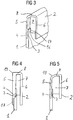
- Fig. 3 shows a perspective view of a cut decorative strip 2, which is a wall of a container body 1 is placed.
- the decorative strip 2 has an outer wall 5 and an inner wall 6, which are connected to one another at the upper edge 8. Between inner wall 6 and outer wall 5 transverse ribs 7 are provided for stiffening at intervals.
- the ribs 7 are not quite up to the lower edge of the inner and outer walls 5, 6 of the decorative strip, but approximately up to the height of the locking lugs 4. However, the ribs 7 are always arranged at a certain distance from the locking lugs 4, so that during injection molding Decorative strip 2 the material flow is not affected and thus a high-quality appearance of the decorative strip is guaranteed.
- a latching lug 4 is arranged in each case between two ribs 7.
- the wall of the container body 1 has at its upper edge a tapered portion 16 which is inserted when plugging the decorative strip 2 into corresponding recesses 17 in the ribs 7 of the decorative strip. Further, on the outwardly facing side of the section 16, the recesses 3 are arranged, in which the locking lugs 4 engage when pushing the decorative strip. In this way, a positive connection between decorative strip 2 and container body 1 is produced.
- the function of the ribs 7 is, on the one hand, to stabilize the decorative strip 2 so that it can also structurally replace part of the front wall and optionally of the side walls 12, 13 of the container body 1.
- the ribs 7 thus ensure a secure latching connection.
- FIGS. 4 and 5 show two variants of a decorative strip 2, which in each case can be plugged onto the same container body 1 to visually differentiate different series of a refrigerator, such as a refrigerator.
- a refrigerator such as a refrigerator.
- the outer wall 5 of the decorative strip 2 flush with the outer wall of the wall of the container body 1.
- the outer wall 5 of the decorative strip 2 is the outer wall 5 of the decorative strip 2, however, thickened and has a portion 18 which covers a portion of the wall of the container body 1 below the locking lug 4.
- the decorative strip 5 thus makes a broader impression from the front.
- the decorative strips 2 can be differentiated by more or less strong rounding at the edge 19 between the upper edge 8 and outer wall 5 from each other. Also in the color, the thickness or the width of the outer and inner walls 5, 6 different decorative strips 2 may differ from each other.
- the recesses 17 are designed to be correspondingly deep, it is also possible, if appropriate, to provide alternative embodiments in which, in contrast to the embodiment shown, the recesses 3 and latching lugs 4 can be omitted.
- the decorative strip 2 then holds only by inserting an upper edge 16 of the front wall 11 and the side walls 12, 13 in corresponding recesses 17 in the ribs 7 of the decorative strip. 2
Landscapes
- Engineering & Computer Science (AREA)
- General Engineering & Computer Science (AREA)
- Combustion & Propulsion (AREA)
- Physics & Mathematics (AREA)
- Mechanical Engineering (AREA)
- Thermal Sciences (AREA)
- Chemical & Material Sciences (AREA)
- Refrigerator Housings (AREA)
- Details Of Rigid Or Semi-Rigid Containers (AREA)
- Packaging Of Machine Parts And Wound Products (AREA)
- Packages (AREA)
- Devices That Are Associated With Refrigeration Equipment (AREA)
- Cultivation Receptacles Or Flower-Pots, Or Pots For Seedlings (AREA)
- Cold Air Circulating Systems And Constructional Details In Refrigerators (AREA)
Description
- Die vorliegende Erfindung betrifft einen Abstellbehälter mit einer Dekorleiste für ein Kältegerät, insbesondere einen Türabsteller, und ein mit einem entsprechenden Abstellbehälter ausgestattetes Kältegerät.
- Zur Differenzierung der unterschiedlichen Baureihen, die von einem Hersteller von Kältegeräten gefertigt werden, ist es bekannt, die Abstellbehälter für das Kühlgut mit unterschiedlichen Dekorleisten zu versehen. So ist aus der
DE 101 17 763 A1 ein Abstellbehälter zur Montage in der Tür eines Kältegeräts bekannt, der aus einem Behälterkorpus und einer Dekorleiste aufgebaut ist, die am Behälterkorpus durch eine Steckverbindung montierbar ist. Die Dekorleiste wird hierbei vor die Frontseite des Abstellbehälters gesetzt. Zur Verankerung der Dekorleiste am Behälterkorpus können am Rand des Behälterkorpus Aussparungen gebildet sein, die im montierten Zustand Vorsprünge an der Unterkante der Dekorleiste aufnehmen und damit eine Verrastung der Dekorleiste am Korpus herstellen. - Aus der
DE 102 08 058 A1 ist ein Steckprofilelement aus zwei eine Nut begrenzenden Schenkeln bekannt, das auch als Dekorelement für einen Türabsteller eines Kühlgeräts verwendbar ist. Es kann von oben auf die Frontseite des Türabstellers aufgesteckt werden, um diese zu versteifen. Auf der der Außenseite des Türabstellers zugewandten Seite des äußeren Schenkels sind elastische Lippen aus einem von dem Werkstoff des Steckelements abweichenden elastischen Werkstoff vorgesehen. - Ferner ist aus der
DE 10 2004 012 497 A1 ein Kühlschrank mit einem Türabsteller bekannt, bei der auf der gekrümmten Kante des Türabstellers eine Dekorleiste aus einem Kunststoffkern und einem metallischen Mantel aufgebracht ist. Die Dekorleiste weist eine Nut auf, in die die Kante des Türabstellers eingeführt ist und wird beim Aufstecken auf die Kante plastisch verformt, um sich dem Verlauf der Kante anzupassen. - Die
US 2006/0082270A1 offenbart einen Abstellbehälter für ein Kältegerät, der einen Behälterkorpus mit einer Frontwand und mit zwei Seitenwänden aufweist. Die Frontwand wird durch eine in einer Öffnung des Abstellbehälters befestigten Frontfläche gebildet. DieUS 2006/0082270A1 offenbart einen Abstellbehälter gemäß dem Oberbegriff des Anspruchs 1. DieDE 33 01649 offenbart einen Kasten mit einem verriegelbaren Deckel und einem als Lamelle ausgebildeten Bügel. -
US 5,437,503 offenbart eine modulare Aufbewahrungsbehälterbaugruppe, die einen geformten Behälter mit Boden-, Seiten- und Rückwänden und einer Frontwand, die nur teilweise so hoch wie die Seitenwände ist, beinhaltet. Ein geformtes Frontmodul beinhaltet einen rechteckigen Rahmen. Der Behälter und der Rahmen beinhalten Verbindungsvorsprünge und Öffnungen, um den Rahmen an dem Behälter zu befestigen. Der Rahmen hat eine zentrale Öffnung und ein Panel ist in der Öffnung positioniert. Der Rahmen und das Panel haben ineinander gepasst Kanten und das Panel beinhaltet eine Rippe, welche die Verbindung zwischen den Kanten schützt. Das Panel beinhaltet Ventilationsöffnungen und ein Schiebesteuerglied, um die Öffnungen freizulegen oder abzudecken. - Der vorliegenden Erfindung liegt die Aufgabe zu Grunde, einen Abstellbehälter sowie ein damit ausgestattetes Kältegerät anzugeben, welcher eine besonders einfache Montage einer austauschbaren Dekorleiste ermöglicht. Ferner ist es eine Aufgabe der Erfindung, einen Abstellbehälter und eine entsprechende Dekorleiste anzugeben, die für die Fertigung durch Spritzgießen besonders geeignet ist.
- Zur Lösung dieser Aufgabe wird ein Abstellbehälter gemäß Anspruch 1 vorgeschlagen. Zumindest die Frontwand wird aus wenigstens zwei übereinander angeordnete Wandabschnitten gebildet ist, die sich in ihrer Farbe und/oder Oberflächenstruktur unterscheiden, und von denen der obere Wandabschnitt als Dekorleiste ausgebildet ist. Beispielsweise kann einer der Wandabschnitte die Farbe gelb, grün, rot, blau oder Mischungen daraus aufweisen, während der andere Wandabschnitt die Farbe des Behälterkorpus aufweist, vorzugsweise weiß. Ferner können sich die wenigstens zwei Wandabschnitte in ihrer Oberflächenstruktur unterscheiden, wobei sie glatt, rauh, mit Einprägungen versehen oder beschichtet ausgebildet sein können. Durch die unterschiedliche Farbe und/oder Oberflächenstruktur wird erfindungsgemäß ein besonderer optischer Eindruck des Abstellbehälters erzeugt, welcher entsprechend einfach für den Einsatz bei unterschiedlichen Kältegeräten variiert werden kann. Im Unterschied zu der Lösung der
DE 102 08 058 A1 wird also nicht eine Dekorleiste auf eine Wand eines Abstellbehälters aufgesteckt, welche auch ohne die Dekorleiste verwendbar ist. Vielmehr bilden die beiden Wandabschnitte gemeinsam zumindest die Frontwand, welche ohne beide Wandabschnitte nicht vollständig ist. - Die Erfindung ermöglicht somit, auf einheitlichen Abstellbehältern in einer Kühl-/Gefrierschrankinnentür unterschiedliche Dekorleisten zu befestigen, um so mit geringen Kosten markenspezifische Innenausstattungssätze, bzw. -baugruppen bereitzustellen. Besonders bevorzugt werden also mehrere verschieden geformte und/oder gefärbte Dekorleisten bereitgestellt, welche jeweils an dem gleichen Behälterkorpus montierbar sind.
- Die mindestens zwei Wandabschnitte sind übereinander angeordnet. Der obere Wandabschnitt ersetzt hierbei einen den oberen Rand enthaltenden Teil zumindest der Frontwand, gegebenenfalls auch der Seitenwände des Abstellbehälters. Der als Dekorleiste ausgebildete obere Wandabschnitt erstreckt sich über ca. 10-40%, besonders bevorzugt 20-30% der Höhe der Frontwand und gegebenenfalls der Seitenwände. Bevorzugt ist der obere Wandabschnitt formstabil, damit er konstruktiv einen Teil der Wand bilden kann. Besonders bevorzugt ist der obere Wandabschnitt in seiner Farbe und/oder Oberflächenstruktur auffällig ausgebildet, während der untere Wandabschnitt die gleiche Farbe und/oder Oberflächenstruktur wie der Behälterkorpus aufweist.
- Die mindestens zwei Wandabschnitte sind gemäß einer ersten Ausführungsform stoffschlüssig miteinander verbunden, z.B. geklebt oder geschweißt. Gemäß einer alternativen Ausführungsform sind die mindestens zwei Wandabschnitte form- und/oder kraftschlüssig miteinander verbunden, beispielsweise durch eine Rast-, Steck-, Klemm-, Schnapp-, Schraub-, Niet- oder Nut-Feder-Verbindung. Möglich ist auch die Kombination einer formschlüssigen Verbindung mit einer stoffschlüssigen Verbindung durch Klebstoff.
- Besonders bevorzugt ist der obere Wandabschnitt als ein formstabiler, abnehmbarer Wandteil ausgebildet.
- Im Gegensatz zu der
DE 101 17 673 A1 wird der abnehmbare Wandteil nicht als Blende vor die Frontwand gesteckt, sondern erstreckt sich zumindest teilweise über die gesamte Stärke der Frontwand, bildet also eine Verlängerung der Frontwand nach oben. Der formstabile abnehmbare Wandteil bildet den oberen Teil der Frontwand und die oberen Teile der beiden Seitenwände, weist also entsprechend drei Schenkel auf, was eine besondere Stabilität des zusammengesetzten Abstellbehälters bewirkt. - Besonders bevorzugt sind sowohl der Behälterkorpus und insbesondere der abnehmbare Wandteil jeweils als Kunststoff-Spritzgussteil ausgebildet. Vorzugsweise ist der abnehmbare Wandteil daher ohne Durchbrüche oder sonstige Formen gestaltet, die den Material fluss beim Spritzgießen beeinträchtigen können. Wie dies erreicht werden kann, wird im Folgenden noch genauer erläutert werden.
- Gemäß einer bevorzugten Ausführungsform ist der abnehmbare Wandteil mit einer formschlüssigen Verbindung an der Frontwand und an den Seitenwänden befestigbar. Hierbei handelt es sich vorzugsweise um eine Rastverbindung, bei welcher der abnehmbare Wandteil an seinem dem Behälterkorpus zugewandten unteren Rand in waagerechter Richtung vorspringende Rastnasen aufweist und der Behälterkorpus an seinem oberen Rand entsprechende Ausnehmungen aufweist, in die die Rastnasen einführbar sind. Alternativ können die Rastnasen auch an dem oberen Rand des Behälterkorpus angeordnet sein und die hierzu korrespondierenden Ausnehmungen in dem unteren Rand des abnehmbaren Randabschnitts.
- Bevorzugt sind mehrere, insbesondere 6-10 Rastnasen in Abständen am unteren Rand des abnehmbaren Wandteils angeordnet, und in entsprechenden Abständen am oberen Rand des Behälterkorpus eine entsprechende Anzahl von Ausnehmungen. Die Rastnasen erstrecken sich bevorzugt jeweils über eine Randlänge von ca. 4-20 mm. Alternativ kann sich eine Rastnase auch über die gesamte Länge des abnehmbaren Wandteils oder des oberen Randes des Behälterkorpus erstrecken, wobei auf dem hierzu komplementären Teil von Wandteil und Behälterkorpus eine entsprechend umlaufende Nut angeordnet ist.
- Vorzugsweise weist der abnehmbare Wandteil eine Innenwand und eine Außenwand auf, die durch Rippen miteinander verbunden sind. Die Rastnasen sind somit vorzugsweise in der Außenwand vorgesehen und stehen in Richtung der Innenwand vor. In den Rippen sind vorzugsweise Ausnehmungen vorgesehen, welche den oberen Rand des Behälterkorpus beim Aufstecken aufnehmen und diesen abstützen, um eine sichere Rastverbindung zwischen Rastnasen und Ausnehmungen zu gewährleisten.
- Die Innenwand, die Außenwand und die Rippen bilden eine saubere Fließfront beim Spritzgießen, so dass der abnehmbare Wandteil mit einer harmonischen, qualitativ hochwertigen Oberfläche durch Spritzgießen herstellbar ist.
- Besonders bevorzugt sind die Rippen des abnehmbaren Abschnitts jeweils von den Rastnasen beabstandet angeordnet. Hierdurch wird die Wirbelbildung beim Spritzgießen minimiert, da das Material jeweils entweder eine Rastnase oder eine Rippe ausfüllen muss. Dadurch ist der abnehmbare Wandteil praktisch ohne Bindenähte und somit mit ansprechend glatten Außenflächen als Spritzgussteil herstellbar. Vorzugsweise ist auch auf ein Kältegerät, insbesondere einen Kühlschrank oder einen Gefrierschrank gerichtet, welcher mit einem erfindungsgemäßen Abstellbehälter ausgestattet ist. Vorzugsweise wird ein Satz aus mehreren Dekorleisten bereitgestellt, welche eine unterschiedliche Farbe und/oder Form aufweisen und jeweils mit dem gleichen Abstellbehälter verbindbar sind. Durch die Farbe und/oder Form können die Dekorleisten der Innenausstattung eines Kältegeräts jeweils ein unterschiedliches Aussehen verleihen, welches z.B. markenspezifisch variiert werden kann.
- Die Dekorleisten können vorzugsweise mit verschiedenen Farben beschichtet sein, um eine unterschiedliche Optik verschiedener Dekorleisten zu bieten. Besonders bevorzugt weist die bzw. eine Dekorleiste eine Metallic-Oberfläche auf.
- Die Erfindung bietet somit einen modular aufgebauten Abstellbehälter, insbesondere Türabsteller.
- Im Folgenden werden Ausführungsbeispiele der Erfindung mit Bezug auf die Zeichnungen näher beschrieben. In den Zeichnungen zeigen:
- Fig. 1
- eine perspektivische Ansicht eines Abstellbehälters für ein Kältegerät in einem Zustand, in dem Behälterkorpus und Dekorleiste getrennt sind;
- Fig. 2
- eine perspektivische Ansicht des Abstellbehälters der
Fig. 1 mit montierter Dekorleiste; - Fig. 3
- eine perspektivische geschnittene Detaildarstellung der Verbindung zwischen Dekorleiste und Behälterkorpus;
- Fig. 4
- eine erste Ausführungsform einer Dekorleiste im Schnitt;
- Fig. 5
- eine zweite Ausführungsform einer Dekorleiste im Schnitt.
-
Fig. 1 zeigt einen Abstellbehälter 10, in diesem Fall einen Türabsteller, welcher bei 15 an der Innentür eines Kühlschranks befestigt werden kann. Der Abstellbehälter, bzw. Türabsteller weist einen Behälterkorpus 1 mit einem Boden und vier Seitenwände 11, 12, 13 und 14 auf, wobei die Frontwand 11 dem Benutzer zugewandt ist und die Rückwand 14 an die Kühlschrankinnentür angrenzt. Die Seitenwände 12, 13 sind im gezeigten Beispiel die kürzeren Seiten. - Wie aus
Fig. 1 ersichtlich ist, wird etwa das obere Viertel der Frontwand 11 und der beiden Seitenwände 12, 13 durch einen abnehmbaren Wandteil 2 gebildet. Dieser weist zwei Seitenschenkel und einen Frontschenkel auf und ist auf den Behälterkorpus 1 aufsetzbar. Vorzugsweise ist diese Befestigung lösbar. Die Frontwand 11 und die Seitenwände 13, 13 des Behälterkorpus 1 sind an ihrem oberen Rand jeweils in einem Abschnitt 16 verjüngt, auf den der abnehmbare Wandteil 2 aufgesetzt wird. In dem verjüngten Randabschnitt 16 sind eine Reihe von Ausnehmungen 3 vorgesehen, und zwar sowohl an der dem Innenraum des Kühlgeräts zugewandten Frontwand 11, als auch an den beiden Seitenwänden 12, 13. In diese Ausnehmungen 3 rasten entsprechende Rastnasen auf der Innenseite des Wandteils 2 ein, welche im Bezug auf dieFiguren 3-5 näher erläutert werden sollen. -
Fig. 2 zeigt den Abstellbehälter 10 derFig. 1 mit bereits montiertem Wandteil 2. Wie man erkennen kann, schließen die Außenseiten des abnehmbaren Wandteils 2 mit den Außenseiten der Front- und Seitenwände 11, 12 und 13 bündig ab, so dass von Außen der Eindruck eines einheitlichen Türabstellers mit ansprechender Oberfläche entsteht. Der abnehmbare Wandteil 2 kann durch entsprechende farbige oder sonstige Ausgestaltung als Dekorleiste dienen. -
Fig. 3 zeigt eine perspektivische Darstellung einer geschnittenen Dekorleiste 2, welche eine Wand eines Behälterkorpus 1 aufgesetzt ist. - Die Dekorleiste 2 weist eine Außenwand 5 und eine Innenwand 6 auf, die am oberen Rand 8 miteinander verbunden sind. Zwischen Innenwand 6 und Außenwand 5 sind zur Versteifung in Abständen Querrippen 7 vorgesehen. Die Rippen 7 reichen nicht ganz bis zum unteren Rand der Innen- und Außenwände 5, 6 der Dekorleiste, jedoch etwa bis zur Höhe der Rastnasen 4. Allerdings sind die Rippen 7 stets in einem gewissen Abstand zu den Rastnasen 4 angeordnet, damit beim Spritzgießen der Dekorleiste 2 der Materialfluss nicht beeinträchtigt wird und somit eine hochwertige Optik der Dekorleiste gewährleistet ist. Besonders bevorzugt ist jeweils zwischen zwei Rippen 7 eine Rastnase 4 angeordnet.
- Die Wand des Behälterkorpus 1 weist an ihrem oberen Rand einen verjüngten Abschnitt 16 auf, welche beim Aufstecken der Dekorleiste 2 in entsprechende Ausnehmungen 17 in den Rippen 7 der Dekorleiste eingeschoben wird. Ferner sind auf der nach außen gewandten Seite des Abschnitts 16 die Ausnehmungen 3 angeordnet, in die beim Aufschieben der Dekorleiste die Rastnasen 4 einrasten. Auf diese Weise wird eine formschlüssige Verbindung zwischen Dekorleiste 2 und Behälterkorpus 1 hergestellt.
- Die Funktion der Rippen 7 ist zum Einen, die Dekorleiste 2 zu stabilisieren, damit diese auch konstruktiv einen Teil der Frontwand und gegebenenfalls der Seitenwände 12, 13 des Behälterkorpus 1 ersetzen kann. Zum Anderen dienen die Rippen 7 mit ihren Ausnehmungen 17 dazu, den Abschnitt 16 abzustützen, wenn die Rastnasen 4 in die Ausnehmungen 4 eingerastet sind. Die Rippen 7 sorgen somit auch für eine sichere Rastverbindung.
- Die
Figuren 4 und 5 zeigen zwei Varianten einer Dekorleiste 2, welche jeweils auf den gleichen Behälterkorpus 1 aufgesteckt werden können, um verschiedene Baureihen eines Kältegeräts, z.B. eines Kühlschranks, optisch zu differenzieren. In der Ausführungsform derFig. 5 ist die Außenwand 5 der Dekorleiste 2 bündig mit der Außenwand der Wand des Behälterkorpus 1. Bei der Ausführungsform derFig. 4 ist die Außenwand 5 der Dekorleiste 2 dagegen verdickt und weist einen Abschnitt 18 auf, welcher unterhalb der Rastnase 4 einen Teil der Wand des Behälterkorpus 1 überdeckt. Insgesamt macht die Dekorleiste 5 somit von vorne einen breiteren Eindruck. - Ferner können die Dekorleisten 2 durch mehr oder weniger starke Abrundungen an der Kante 19 zwischen oberem Rand 8 und Außenwand 5 voneinander differenziert werden. Auch in der Farbe, der Dicke oder der Breite der Außen- und Innenwände 5, 6 können sich verschiedene Dekorleisten 2 voneinander unterscheiden.
- Werden die Ausnehmungen 17 entsprechend tief gestaltet, können gegebenenfalls auch alternative Ausführungsformen vorgesehen werden, bei denen im Gegensatz zu der gezeigten Ausführungsform die Ausnehmungen 3 und Rastnasen 4 weggelassen werden können. Die Dekorleiste 2 hält dann lediglich durch Einschieben eines oberen Randes 16 der Frontwand 11 und der Seitenwände 12, 13 in entsprechende Ausnehmungen 17 in den Rippen 7 der Dekorleiste 2.
Claims (13)
- Abstellbehälter (10) für ein Kältegerät, umfassend einen Behälterkorpus (1) mit einer Frontwand (11) und zwei Seitenwände (12, 13), wobei zumindest die Frontwand (11) aus wenigstens zwei übereinander angeordnete Wandabschnitten gebildet ist, die sich in ihrer Farbe und/oder Oberflächenstruktur unterscheiden, und von denen der obere Wandabschnitt als abnehmbare, formstabile Dekorleiste (2) ausgebildet ist, und der obere Wandabschnitt einen oberen Rand der Frontwand (11) bildet, dadurch gekennzeichnet, dass die Dekorleiste (2) den oberen Teil der Frontwand (11) und die oberen Teile der beiden Seitenwände (12, 13) bildet, und dass sich der obere Wandabschnitt über 10% bis 40% der Höhe der Frontwand (11) erstreckt.
- Abstellbehälter nach Anspruch 1, dadurch gekennzeichnet, dass die beiden Wandabschnitte stoffschlüssig miteinander verbunden sind.
- Abstellbehälter nach Anspruch 1, dadurch gekennzeichnet, dass die beiden Wandabschnitte form- und/oder kraftschlüssig miteinander verbunden sind.
- Abstellbehälter (10) nach einem der vorhergehenden Ansprüche, dadurch gekennzeichnet, dass der Behälterkorpus (1) und die wenigstens zwei Wandabschnitte (2) jeweils als Kunststoff-Spritzgussteil ausgebildet sind.
- Abstellbehälter (10) nach einem der Ansprüche 1 bis 4, dadurch gekennzeichnet, dass die Dekorleiste (2) mit einer formschlüssigen Verbindung an der Frontwand (11) und ggf. den Seitenwänden (12,13) befestigbar ist.
- Abstellbehälter (10) nach Anspruch 5, dadurch gekennzeichnet, dass die Dekorleiste (2) an seinem dem Behälterkorpus (1) zugewandten unteren Rand in waagrechter Richtung vorspringende Rastnasen (4) aufweist und der Behälterkorpus (1) an seinem oberen Rand (16) entsprechende Ausnehmungen (3) aufweist, in die die Rastnasen (4) einführbar sind und die mit diesen zusammen eine Rastverbindung bilden.
- Abstellbehälter (10) nach Anspruch 6 dadurch gekennzeichnet, dass am unteren Rand der Dekorleiste (2) in Abständen mehrere vorspringende Rastnasen (4) angeordnet sind und am oberen Rand des Behälterkorpus (1) eine in entsprechenden Abständen angeordnete Anzahl von Ausnehmungen (3).
- Abstellbehälter (10) nach einem der vorhergehenden Ansprüche, dadurch gekennzeichnet, dass die Dekorleiste (2) eine Innenwand (6) und eine Außenwand (5) aufweist, die durch Rippen (7) miteinander verbunden sind.
- Abstellbehälter (10) nach Anspruch 8, dadurch gekennzeichnet, dass die Rastnasen (4) in der Außenwand (5) vorgesehen sind.
- Abstellbehälter (10) nach Anspruch 8 oder 9 , dadurch gekennzeichnet, dass die Rippen (7) jeweils im Abstand zu den Rastnasen (4) angeordnet sind.
- Abstellbehälter (10) nach einem der Ansprüche, dadurch gekennzeichnet, dass er ein Türabsteller eines Kühlschranks oder Gefrierschranks ist.
- Kältegerät, insbesondere Haushalts-Kühlschrank oder -Gefrierschrank, dadurch gekennzeichnet, dass es mit einem Abstellbehälter (10) nach einem der Ansprüche 1 bis 11 ausgestattet ist.
- Kältegerät nach Anspruch 12, gekennzeichnet durch einen Satz aus mehreren Dekorleisten (2) die eine unterschiedliche Farbe und/oder Form aufweisen und mit jeweils dem gleichen Behälterkorpus (1) verbindbar sind.
Priority Applications (1)
| Application Number | Priority Date | Filing Date | Title |
|---|---|---|---|
| PL08863769T PL2235451T3 (pl) | 2007-12-21 | 2008-12-10 | Pojemnik do przechowywania dla urządzenia chłodniczego |
Applications Claiming Priority (4)
| Application Number | Priority Date | Filing Date | Title |
|---|---|---|---|
| DE200710062005 DE102007062005A1 (de) | 2007-12-21 | 2007-12-21 | Kältegerät |
| DE102008019261A DE102008019261A1 (de) | 2008-04-11 | 2008-04-11 | Haushalts-Kältegerät mit mindestens einem Abstellbehältnis |
| DE200820005350 DE202008005350U1 (de) | 2008-04-17 | 2008-04-17 | Abstellbehälter für ein Kältegerät |
| PCT/EP2008/067244 WO2009080528A1 (de) | 2007-12-21 | 2008-12-10 | Abstellbehälter für ein kältegerät |
Publications (2)
| Publication Number | Publication Date |
|---|---|
| EP2235451A1 EP2235451A1 (de) | 2010-10-06 |
| EP2235451B1 true EP2235451B1 (de) | 2017-06-07 |
Family
ID=40600258
Family Applications (3)
| Application Number | Title | Priority Date | Filing Date |
|---|---|---|---|
| EP08864319.2A Active EP2225513B1 (de) | 2007-12-21 | 2008-12-08 | Kältegerät |
| EP08863769.9A Active EP2235451B1 (de) | 2007-12-21 | 2008-12-10 | Abstellbehälter für ein kältegerät |
| EP08863543.8A Active EP2235455B1 (de) | 2007-12-21 | 2008-12-10 | Haushalts-kältegerät mit mindestens einem abstellbehältnis |
Family Applications Before (1)
| Application Number | Title | Priority Date | Filing Date |
|---|---|---|---|
| EP08864319.2A Active EP2225513B1 (de) | 2007-12-21 | 2008-12-08 | Kältegerät |
Family Applications After (1)
| Application Number | Title | Priority Date | Filing Date |
|---|---|---|---|
| EP08863543.8A Active EP2235455B1 (de) | 2007-12-21 | 2008-12-10 | Haushalts-kältegerät mit mindestens einem abstellbehältnis |
Country Status (4)
| Country | Link |
|---|---|
| EP (3) | EP2225513B1 (de) |
| CN (3) | CN101903726B (de) |
| PL (3) | PL2225513T3 (de) |
| WO (3) | WO2009080483A1 (de) |
Families Citing this family (11)
| Publication number | Priority date | Publication date | Assignee | Title |
|---|---|---|---|---|
| KR101717525B1 (ko) * | 2010-07-13 | 2017-03-17 | 엘지전자 주식회사 | 냉장고 |
| DE102011007318A1 (de) * | 2011-04-13 | 2012-10-18 | BSH Bosch und Siemens Hausgeräte GmbH | Teilesatz für eine Kältegerätetür |
| CN102853622B (zh) * | 2012-04-23 | 2014-08-13 | 合肥美的电冰箱有限公司 | 用于冰箱的储物盒组件及具有它的冰箱 |
| CN103277960B (zh) * | 2013-04-28 | 2015-05-27 | 海尔集团公司 | 抽屉门体及其安装方法 |
| CN104344669B (zh) | 2013-07-31 | 2018-07-13 | 博西华电器(江苏)有限公司 | 具有抽屉的冰箱 |
| WO2016102162A1 (en) | 2014-12-25 | 2016-06-30 | BSH Hausgeräte GmbH | A home appliance having drawer-type movable container with a handle |
| CN104949452B (zh) * | 2015-06-30 | 2017-08-15 | 合肥美的电冰箱有限公司 | 一种果菜盒组件及应用该组件的冰箱 |
| DE102015212350A1 (de) * | 2015-07-01 | 2017-01-05 | BSH Hausgeräte GmbH | Haushaltsgeräte-Bauteil mit einem coextrudierten Dekorteil |
| CN107178959B (zh) * | 2017-06-29 | 2019-12-27 | 青岛海尔股份有限公司 | 冰箱及其瓶座 |
| DE102018203431A1 (de) * | 2018-03-07 | 2019-09-12 | BSH Hausgeräte GmbH | Kühlgutabstellfach mit L-förmigen Rahmen, Tür sowie Haushaltskältegerät |
| DE102021104066A1 (de) | 2021-02-04 | 2022-08-04 | Liebherr-Hausgeräte Ochsenhausen GmbH | Griffleiste für eine Schublade eines Kühl- und / oder Gefriergeräts |
Citations (1)
| Publication number | Priority date | Publication date | Assignee | Title |
|---|---|---|---|---|
| US5437503A (en) * | 1993-06-01 | 1995-08-01 | General Electric Company | Modular storage drawer assembly for use in a refrigerator |
Family Cites Families (10)
| Publication number | Priority date | Publication date | Assignee | Title |
|---|---|---|---|---|
| CN2384180Y (zh) * | 1999-07-09 | 2000-06-21 | 海尔集团公司 | 冰箱组合式抽屉 |
| DE10117762A1 (de) * | 2001-04-09 | 2002-10-10 | Bsh Bosch Siemens Hausgeraete | Abstellbehälter für Kältegeräte |
| DE10117763A1 (de) * | 2001-04-09 | 2002-10-10 | Bsh Bosch Siemens Hausgeraete | Abstellbehälter für Kältegeräte |
| US20030020384A1 (en) * | 2001-07-16 | 2003-01-30 | Bush Roger K. | Crisper trim enhancement |
| CN2510804Y (zh) * | 2001-11-15 | 2002-09-11 | 安徽博西华制冷有限公司 | 具有推拉机构的冰箱抽屉 |
| US7073876B2 (en) * | 2002-07-15 | 2006-07-11 | Maytag Corporation | Exchangeable components for color customizing of appliances |
| DE102004012497A1 (de) * | 2004-03-15 | 2005-10-06 | BSH Bosch und Siemens Hausgeräte GmbH | Kühlschrank mit Kühlgutabsteller |
| US7293846B2 (en) * | 2004-10-15 | 2007-11-13 | Whirlpool Corporation | Storage bin assembly for a refrigerator |
| DE102005022516A1 (de) * | 2005-05-11 | 2006-11-16 | BSH Bosch und Siemens Hausgeräte GmbH | Türabsteller für ein Kältegerät |
| DE202005012342U1 (de) * | 2005-08-05 | 2005-10-20 | BSH Bosch und Siemens Hausgeräte GmbH | Modular Kühlgutbehälter |
-
2008
- 2008-12-08 EP EP08864319.2A patent/EP2225513B1/de active Active
- 2008-12-08 WO PCT/EP2008/067028 patent/WO2009080483A1/de active Application Filing
- 2008-12-08 PL PL08864319.2T patent/PL2225513T3/pl unknown
- 2008-12-08 CN CN2008801223090A patent/CN101903726B/zh active Active
- 2008-12-10 EP EP08863769.9A patent/EP2235451B1/de active Active
- 2008-12-10 WO PCT/EP2008/067247 patent/WO2009080529A2/de active Application Filing
- 2008-12-10 CN CN200880122260.9A patent/CN101903725B/zh active Active
- 2008-12-10 CN CN2008801222628A patent/CN101903722A/zh active Pending
- 2008-12-10 WO PCT/EP2008/067244 patent/WO2009080528A1/de active Application Filing
- 2008-12-10 PL PL08863543T patent/PL2235455T3/pl unknown
- 2008-12-10 EP EP08863543.8A patent/EP2235455B1/de active Active
- 2008-12-10 PL PL08863769T patent/PL2235451T3/pl unknown
Patent Citations (1)
| Publication number | Priority date | Publication date | Assignee | Title |
|---|---|---|---|---|
| US5437503A (en) * | 1993-06-01 | 1995-08-01 | General Electric Company | Modular storage drawer assembly for use in a refrigerator |
Also Published As
| Publication number | Publication date |
|---|---|
| CN101903725A (zh) | 2010-12-01 |
| WO2009080483A1 (de) | 2009-07-02 |
| EP2235455A2 (de) | 2010-10-06 |
| EP2235451A1 (de) | 2010-10-06 |
| PL2235451T3 (pl) | 2017-10-31 |
| EP2225513A1 (de) | 2010-09-08 |
| CN101903726A (zh) | 2010-12-01 |
| EP2235455B1 (de) | 2016-10-26 |
| EP2225513B1 (de) | 2016-03-16 |
| CN101903725B (zh) | 2014-12-03 |
| PL2225513T3 (pl) | 2016-09-30 |
| WO2009080529A2 (de) | 2009-07-02 |
| PL2235455T3 (pl) | 2017-03-31 |
| WO2009080529A3 (de) | 2009-08-27 |
| CN101903726B (zh) | 2013-02-06 |
| WO2009080528A1 (de) | 2009-07-02 |
| CN101903722A (zh) | 2010-12-01 |
Similar Documents
| Publication | Publication Date | Title |
|---|---|---|
| EP2235451B1 (de) | Abstellbehälter für ein kältegerät | |
| EP2286163B1 (de) | Kühlgutabstellfach | |
| EP2464926B1 (de) | Abstellfach für ein kältegerät | |
| EP1867376A1 (de) | Filterlüfter mit einer Schnellbefestigungseinrichtung | |
| DE202008005350U1 (de) | Abstellbehälter für ein Kältegerät | |
| DE102008063390A1 (de) | Kältegerät mit einem Ablageboden | |
| WO2006120097A1 (de) | Innenbehälter für ein kältegerät | |
| EP2429046A2 (de) | Elektrischer Schaltschrank | |
| EP1379820B3 (de) | Kältegerät mit einem abstellbehälter | |
| EP2467657B1 (de) | Tür für ein haushaltsgerät mit griffeinsatz | |
| DE10236215B3 (de) | Aufbewahrungsanordnung | |
| EP2465403A2 (de) | Geschirrspülmaschine | |
| EP3457056B1 (de) | Türabsteller für ein kältergerät | |
| WO2011124446A2 (de) | Türabsteller für ein kältegerät | |
| EP2464928B1 (de) | Kältegerät | |
| DE20213208U1 (de) | Kühlschrank und Kühlschranktürbaugruppe | |
| EP3537077B1 (de) | Kühlgutabstellfach mit l-förmigen rahmen, tür sowie haushaltskältegerät | |
| EP2023063A2 (de) | Türrand-Abschlusselement einer Haushaltsgeräte-Tür | |
| EP1608916B1 (de) | Warmwasserspeicher | |
| DE4211324A1 (de) | Vorrichtung zur Aufnahme eines Tafelelements | |
| DE102012101902B3 (de) | Radkappe und Verfahren zur Herstellung und Verpackung derselben | |
| DE4333653C2 (de) | Befestigung eines Anbauteils, wie Zierblende, an einem Kraftfahrzeug | |
| DE29613604U1 (de) | Ablage für eine Kühlschranktür | |
| WO2011128203A1 (de) | Abstellbehälter mit dekorblende | |
| DE102010023282A1 (de) | Luftfilter für ein Kraftfahrzeug |
Legal Events
| Date | Code | Title | Description |
|---|---|---|---|
| PUAI | Public reference made under article 153(3) epc to a published international application that has entered the european phase |
Free format text: ORIGINAL CODE: 0009012 |
|
| 17P | Request for examination filed |
Effective date: 20100721 |
|
| AK | Designated contracting states |
Kind code of ref document: A1 Designated state(s): AT BE BG CH CY CZ DE DK EE ES FI FR GB GR HR HU IE IS IT LI LT LU LV MC MT NL NO PL PT RO SE SI SK TR |
|
| AX | Request for extension of the european patent |
Extension state: AL BA MK RS |
|
| DAX | Request for extension of the european patent (deleted) | ||
| RAP1 | Party data changed (applicant data changed or rights of an application transferred) |
Owner name: BSH HAUSGERAETE GMBH |
|
| 17Q | First examination report despatched |
Effective date: 20151124 |
|
| RIC1 | Information provided on ipc code assigned before grant |
Ipc: F25D 25/00 20060101ALI20161121BHEP Ipc: F25D 23/04 20060101AFI20161121BHEP |
|
| GRAP | Despatch of communication of intention to grant a patent |
Free format text: ORIGINAL CODE: EPIDOSNIGR1 |
|
| STAA | Information on the status of an ep patent application or granted ep patent |
Free format text: STATUS: GRANT OF PATENT IS INTENDED |
|
| INTG | Intention to grant announced |
Effective date: 20170125 |
|
| GRAS | Grant fee paid |
Free format text: ORIGINAL CODE: EPIDOSNIGR3 |
|
| GRAA | (expected) grant |
Free format text: ORIGINAL CODE: 0009210 |
|
| STAA | Information on the status of an ep patent application or granted ep patent |
Free format text: STATUS: THE PATENT HAS BEEN GRANTED |
|
| AK | Designated contracting states |
Kind code of ref document: B1 Designated state(s): AT BE BG CH CY CZ DE DK EE ES FI FR GB GR HR HU IE IS IT LI LT LU LV MC MT NL NO PL PT RO SE SI SK TR |
|
| REG | Reference to a national code |
Ref country code: GB Ref legal event code: FG4D Free format text: NOT ENGLISH |
|
| GRAA | (expected) grant |
Free format text: ORIGINAL CODE: 0009210 |
|
| REG | Reference to a national code |
Ref country code: CH Ref legal event code: EP Ref country code: AT Ref legal event code: REF Ref document number: 899551 Country of ref document: AT Kind code of ref document: T Effective date: 20170615 |
|
| REG | Reference to a national code |
Ref country code: IE Ref legal event code: FG4D Free format text: LANGUAGE OF EP DOCUMENT: GERMAN |
|
| REG | Reference to a national code |
Ref country code: DE Ref legal event code: R096 Ref document number: 502008015374 Country of ref document: DE |
|
| REG | Reference to a national code |
Ref country code: NL Ref legal event code: MP Effective date: 20170607 |
|
| REG | Reference to a national code |
Ref country code: LT Ref legal event code: MG4D |
|
| PG25 | Lapsed in a contracting state [announced via postgrant information from national office to epo] |
Ref country code: FI Free format text: LAPSE BECAUSE OF FAILURE TO SUBMIT A TRANSLATION OF THE DESCRIPTION OR TO PAY THE FEE WITHIN THE PRESCRIBED TIME-LIMIT Effective date: 20170607 Ref country code: ES Free format text: LAPSE BECAUSE OF FAILURE TO SUBMIT A TRANSLATION OF THE DESCRIPTION OR TO PAY THE FEE WITHIN THE PRESCRIBED TIME-LIMIT Effective date: 20170607 Ref country code: NO Free format text: LAPSE BECAUSE OF FAILURE TO SUBMIT A TRANSLATION OF THE DESCRIPTION OR TO PAY THE FEE WITHIN THE PRESCRIBED TIME-LIMIT Effective date: 20170907 Ref country code: LT Free format text: LAPSE BECAUSE OF FAILURE TO SUBMIT A TRANSLATION OF THE DESCRIPTION OR TO PAY THE FEE WITHIN THE PRESCRIBED TIME-LIMIT Effective date: 20170607 Ref country code: GR Free format text: LAPSE BECAUSE OF FAILURE TO SUBMIT A TRANSLATION OF THE DESCRIPTION OR TO PAY THE FEE WITHIN THE PRESCRIBED TIME-LIMIT Effective date: 20170908 Ref country code: HR Free format text: LAPSE BECAUSE OF FAILURE TO SUBMIT A TRANSLATION OF THE DESCRIPTION OR TO PAY THE FEE WITHIN THE PRESCRIBED TIME-LIMIT Effective date: 20170607 |
|
| PG25 | Lapsed in a contracting state [announced via postgrant information from national office to epo] |
Ref country code: BG Free format text: LAPSE BECAUSE OF FAILURE TO SUBMIT A TRANSLATION OF THE DESCRIPTION OR TO PAY THE FEE WITHIN THE PRESCRIBED TIME-LIMIT Effective date: 20170907 Ref country code: LV Free format text: LAPSE BECAUSE OF FAILURE TO SUBMIT A TRANSLATION OF THE DESCRIPTION OR TO PAY THE FEE WITHIN THE PRESCRIBED TIME-LIMIT Effective date: 20170607 Ref country code: NL Free format text: LAPSE BECAUSE OF FAILURE TO SUBMIT A TRANSLATION OF THE DESCRIPTION OR TO PAY THE FEE WITHIN THE PRESCRIBED TIME-LIMIT Effective date: 20170607 Ref country code: SE Free format text: LAPSE BECAUSE OF FAILURE TO SUBMIT A TRANSLATION OF THE DESCRIPTION OR TO PAY THE FEE WITHIN THE PRESCRIBED TIME-LIMIT Effective date: 20170607 |
|
| PG25 | Lapsed in a contracting state [announced via postgrant information from national office to epo] |
Ref country code: SK Free format text: LAPSE BECAUSE OF FAILURE TO SUBMIT A TRANSLATION OF THE DESCRIPTION OR TO PAY THE FEE WITHIN THE PRESCRIBED TIME-LIMIT Effective date: 20170607 Ref country code: RO Free format text: LAPSE BECAUSE OF FAILURE TO SUBMIT A TRANSLATION OF THE DESCRIPTION OR TO PAY THE FEE WITHIN THE PRESCRIBED TIME-LIMIT Effective date: 20170607 Ref country code: CZ Free format text: LAPSE BECAUSE OF FAILURE TO SUBMIT A TRANSLATION OF THE DESCRIPTION OR TO PAY THE FEE WITHIN THE PRESCRIBED TIME-LIMIT Effective date: 20170607 Ref country code: EE Free format text: LAPSE BECAUSE OF FAILURE TO SUBMIT A TRANSLATION OF THE DESCRIPTION OR TO PAY THE FEE WITHIN THE PRESCRIBED TIME-LIMIT Effective date: 20170607 |
|
| PG25 | Lapsed in a contracting state [announced via postgrant information from national office to epo] |
Ref country code: IS Free format text: LAPSE BECAUSE OF FAILURE TO SUBMIT A TRANSLATION OF THE DESCRIPTION OR TO PAY THE FEE WITHIN THE PRESCRIBED TIME-LIMIT Effective date: 20171007 |
|
| REG | Reference to a national code |
Ref country code: DE Ref legal event code: R097 Ref document number: 502008015374 Country of ref document: DE |
|
| PLBE | No opposition filed within time limit |
Free format text: ORIGINAL CODE: 0009261 |
|
| STAA | Information on the status of an ep patent application or granted ep patent |
Free format text: STATUS: NO OPPOSITION FILED WITHIN TIME LIMIT |
|
| PG25 | Lapsed in a contracting state [announced via postgrant information from national office to epo] |
Ref country code: DK Free format text: LAPSE BECAUSE OF FAILURE TO SUBMIT A TRANSLATION OF THE DESCRIPTION OR TO PAY THE FEE WITHIN THE PRESCRIBED TIME-LIMIT Effective date: 20170607 |
|
| 26N | No opposition filed |
Effective date: 20180308 |
|
| PG25 | Lapsed in a contracting state [announced via postgrant information from national office to epo] |
Ref country code: SI Free format text: LAPSE BECAUSE OF FAILURE TO SUBMIT A TRANSLATION OF THE DESCRIPTION OR TO PAY THE FEE WITHIN THE PRESCRIBED TIME-LIMIT Effective date: 20170607 |
|
| REG | Reference to a national code |
Ref country code: CH Ref legal event code: PL |
|
| GBPC | Gb: european patent ceased through non-payment of renewal fee |
Effective date: 20171210 |
|
| REG | Reference to a national code |
Ref country code: IE Ref legal event code: MM4A |
|
| PG25 | Lapsed in a contracting state [announced via postgrant information from national office to epo] |
Ref country code: LU Free format text: LAPSE BECAUSE OF NON-PAYMENT OF DUE FEES Effective date: 20171210 Ref country code: MT Free format text: LAPSE BECAUSE OF FAILURE TO SUBMIT A TRANSLATION OF THE DESCRIPTION OR TO PAY THE FEE WITHIN THE PRESCRIBED TIME-LIMIT Effective date: 20170607 |
|
| REG | Reference to a national code |
Ref country code: FR Ref legal event code: ST Effective date: 20180831 |
|
| REG | Reference to a national code |
Ref country code: BE Ref legal event code: MM Effective date: 20171231 |
|
| PG25 | Lapsed in a contracting state [announced via postgrant information from national office to epo] |
Ref country code: FR Free format text: LAPSE BECAUSE OF NON-PAYMENT OF DUE FEES Effective date: 20180102 Ref country code: IE Free format text: LAPSE BECAUSE OF NON-PAYMENT OF DUE FEES Effective date: 20171210 |
|
| PG25 | Lapsed in a contracting state [announced via postgrant information from national office to epo] |
Ref country code: BE Free format text: LAPSE BECAUSE OF NON-PAYMENT OF DUE FEES Effective date: 20171231 Ref country code: GB Free format text: LAPSE BECAUSE OF NON-PAYMENT OF DUE FEES Effective date: 20171210 Ref country code: CH Free format text: LAPSE BECAUSE OF NON-PAYMENT OF DUE FEES Effective date: 20171231 Ref country code: LI Free format text: LAPSE BECAUSE OF NON-PAYMENT OF DUE FEES Effective date: 20171231 |
|
| REG | Reference to a national code |
Ref country code: AT Ref legal event code: MM01 Ref document number: 899551 Country of ref document: AT Kind code of ref document: T Effective date: 20171210 |
|
| PG25 | Lapsed in a contracting state [announced via postgrant information from national office to epo] |
Ref country code: AT Free format text: LAPSE BECAUSE OF NON-PAYMENT OF DUE FEES Effective date: 20171210 |
|
| PG25 | Lapsed in a contracting state [announced via postgrant information from national office to epo] |
Ref country code: MC Free format text: LAPSE BECAUSE OF FAILURE TO SUBMIT A TRANSLATION OF THE DESCRIPTION OR TO PAY THE FEE WITHIN THE PRESCRIBED TIME-LIMIT Effective date: 20170607 Ref country code: HU Free format text: LAPSE BECAUSE OF FAILURE TO SUBMIT A TRANSLATION OF THE DESCRIPTION OR TO PAY THE FEE WITHIN THE PRESCRIBED TIME-LIMIT; INVALID AB INITIO Effective date: 20081210 |
|
| PG25 | Lapsed in a contracting state [announced via postgrant information from national office to epo] |
Ref country code: CY Free format text: LAPSE BECAUSE OF NON-PAYMENT OF DUE FEES Effective date: 20170607 |
|
| PG25 | Lapsed in a contracting state [announced via postgrant information from national office to epo] |
Ref country code: PT Free format text: LAPSE BECAUSE OF FAILURE TO SUBMIT A TRANSLATION OF THE DESCRIPTION OR TO PAY THE FEE WITHIN THE PRESCRIBED TIME-LIMIT Effective date: 20170607 |
|
| REG | Reference to a national code |
Ref country code: DE Ref legal event code: R084 Ref document number: 502008015374 Country of ref document: DE |
|
| PGFP | Annual fee paid to national office [announced via postgrant information from national office to epo] |
Ref country code: TR Payment date: 20231201 Year of fee payment: 16 Ref country code: DE Payment date: 20231231 Year of fee payment: 16 |
|
| PGFP | Annual fee paid to national office [announced via postgrant information from national office to epo] |
Ref country code: PL Payment date: 20231201 Year of fee payment: 16 |
|
| PGFP | Annual fee paid to national office [announced via postgrant information from national office to epo] |
Ref country code: IT Payment date: 20231229 Year of fee payment: 16 |