EP2233811A2 - Kunststoffrohr - Google Patents
Kunststoffrohr Download PDFInfo
- Publication number
- EP2233811A2 EP2233811A2 EP10003156A EP10003156A EP2233811A2 EP 2233811 A2 EP2233811 A2 EP 2233811A2 EP 10003156 A EP10003156 A EP 10003156A EP 10003156 A EP10003156 A EP 10003156A EP 2233811 A2 EP2233811 A2 EP 2233811A2
- Authority
- EP
- European Patent Office
- Prior art keywords
- tube
- layers
- plastic pipe
- layer
- pipe according
- Prior art date
- Legal status (The legal status is an assumption and is not a legal conclusion. Google has not performed a legal analysis and makes no representation as to the accuracy of the status listed.)
- Withdrawn
Links
- 239000004033 plastic Substances 0.000 title claims description 32
- 229920003023 plastic Polymers 0.000 title claims description 32
- 239000000835 fiber Substances 0.000 claims abstract description 26
- 230000002787 reinforcement Effects 0.000 claims abstract description 14
- 230000007935 neutral effect Effects 0.000 claims abstract description 11
- 238000001125 extrusion Methods 0.000 claims abstract description 4
- 238000000034 method Methods 0.000 claims abstract description 4
- 230000008569 process Effects 0.000 claims abstract description 4
- 230000003014 reinforcing effect Effects 0.000 claims description 24
- 239000012779 reinforcing material Substances 0.000 claims description 13
- 229920005601 base polymer Polymers 0.000 claims description 5
- 229920001169 thermoplastic Polymers 0.000 claims description 2
- 239000012815 thermoplastic material Substances 0.000 claims description 2
- 239000004416 thermosoftening plastic Substances 0.000 claims description 2
- 239000007767 bonding agent Substances 0.000 claims 1
- 239000000463 material Substances 0.000 abstract description 7
- 239000003365 glass fiber Substances 0.000 abstract description 4
- 229920000642 polymer Polymers 0.000 abstract description 3
- 238000005452 bending Methods 0.000 description 6
- 238000010276 construction Methods 0.000 description 6
- 239000012530 fluid Substances 0.000 description 4
- 239000007789 gas Substances 0.000 description 3
- 239000000654 additive Substances 0.000 description 2
- 239000011347 resin Substances 0.000 description 2
- 229920005989 resin Polymers 0.000 description 2
- 239000000126 substance Substances 0.000 description 2
- 229920001187 thermosetting polymer Polymers 0.000 description 2
- 229920000049 Carbon (fiber) Polymers 0.000 description 1
- VGGSQFUCUMXWEO-UHFFFAOYSA-N Ethene Chemical compound C=C VGGSQFUCUMXWEO-UHFFFAOYSA-N 0.000 description 1
- 241000208202 Linaceae Species 0.000 description 1
- 235000004431 Linum usitatissimum Nutrition 0.000 description 1
- 244000089486 Phragmites australis subsp australis Species 0.000 description 1
- 239000004743 Polypropylene Substances 0.000 description 1
- 229910000831 Steel Inorganic materials 0.000 description 1
- 230000006750 UV protection Effects 0.000 description 1
- 229920000122 acrylonitrile butadiene styrene Polymers 0.000 description 1
- 239000004676 acrylonitrile butadiene styrene Substances 0.000 description 1
- 239000002318 adhesion promoter Substances 0.000 description 1
- 239000004760 aramid Substances 0.000 description 1
- 229920006231 aramid fiber Polymers 0.000 description 1
- 230000004888 barrier function Effects 0.000 description 1
- 239000004917 carbon fiber Substances 0.000 description 1
- 239000002131 composite material Substances 0.000 description 1
- 238000004132 cross linking Methods 0.000 description 1
- 230000001419 dependent effect Effects 0.000 description 1
- 238000009826 distribution Methods 0.000 description 1
- 230000000694 effects Effects 0.000 description 1
- 230000007613 environmental effect Effects 0.000 description 1
- 230000002349 favourable effect Effects 0.000 description 1
- 239000011152 fibreglass Substances 0.000 description 1
- 238000005187 foaming Methods 0.000 description 1
- 239000013538 functional additive Substances 0.000 description 1
- 229920001903 high density polyethylene Polymers 0.000 description 1
- 239000004700 high-density polyethylene Substances 0.000 description 1
- 230000001976 improved effect Effects 0.000 description 1
- 230000001939 inductive effect Effects 0.000 description 1
- 229910052500 inorganic mineral Inorganic materials 0.000 description 1
- 238000002372 labelling Methods 0.000 description 1
- 239000007788 liquid Substances 0.000 description 1
- 229920001684 low density polyethylene Polymers 0.000 description 1
- 239000004702 low-density polyethylene Substances 0.000 description 1
- 238000004519 manufacturing process Methods 0.000 description 1
- 239000011159 matrix material Substances 0.000 description 1
- 229910052751 metal Inorganic materials 0.000 description 1
- 239000002184 metal Substances 0.000 description 1
- 239000013528 metallic particle Substances 0.000 description 1
- 150000002739 metals Chemical class 0.000 description 1
- 244000005700 microbiome Species 0.000 description 1
- 239000011707 mineral Substances 0.000 description 1
- 230000003287 optical effect Effects 0.000 description 1
- 239000002245 particle Substances 0.000 description 1
- 239000011505 plaster Substances 0.000 description 1
- 229920000915 polyvinyl chloride Polymers 0.000 description 1
- 239000004800 polyvinyl chloride Substances 0.000 description 1
- 230000009467 reduction Effects 0.000 description 1
- 239000012744 reinforcing agent Substances 0.000 description 1
- 239000010959 steel Substances 0.000 description 1
- 230000000007 visual effect Effects 0.000 description 1
- 239000013585 weight reducing agent Substances 0.000 description 1
- 238000003466 welding Methods 0.000 description 1
Images
Classifications
-
- F—MECHANICAL ENGINEERING; LIGHTING; HEATING; WEAPONS; BLASTING
- F16—ENGINEERING ELEMENTS AND UNITS; GENERAL MEASURES FOR PRODUCING AND MAINTAINING EFFECTIVE FUNCTIONING OF MACHINES OR INSTALLATIONS; THERMAL INSULATION IN GENERAL
- F16L—PIPES; JOINTS OR FITTINGS FOR PIPES; SUPPORTS FOR PIPES, CABLES OR PROTECTIVE TUBING; MEANS FOR THERMAL INSULATION IN GENERAL
- F16L9/00—Rigid pipes
- F16L9/12—Rigid pipes of plastics with or without reinforcement
- F16L9/121—Rigid pipes of plastics with or without reinforcement with three layers
-
- B—PERFORMING OPERATIONS; TRANSPORTING
- B32—LAYERED PRODUCTS
- B32B—LAYERED PRODUCTS, i.e. PRODUCTS BUILT-UP OF STRATA OF FLAT OR NON-FLAT, e.g. CELLULAR OR HONEYCOMB, FORM
- B32B1/00—Layered products having a non-planar shape
- B32B1/08—Tubular products
-
- B—PERFORMING OPERATIONS; TRANSPORTING
- B32—LAYERED PRODUCTS
- B32B—LAYERED PRODUCTS, i.e. PRODUCTS BUILT-UP OF STRATA OF FLAT OR NON-FLAT, e.g. CELLULAR OR HONEYCOMB, FORM
- B32B27/00—Layered products comprising a layer of synthetic resin
- B32B27/12—Layered products comprising a layer of synthetic resin next to a fibrous or filamentary layer
-
- B—PERFORMING OPERATIONS; TRANSPORTING
- B32—LAYERED PRODUCTS
- B32B—LAYERED PRODUCTS, i.e. PRODUCTS BUILT-UP OF STRATA OF FLAT OR NON-FLAT, e.g. CELLULAR OR HONEYCOMB, FORM
- B32B27/00—Layered products comprising a layer of synthetic resin
- B32B27/18—Layered products comprising a layer of synthetic resin characterised by the use of special additives
-
- B—PERFORMING OPERATIONS; TRANSPORTING
- B32—LAYERED PRODUCTS
- B32B—LAYERED PRODUCTS, i.e. PRODUCTS BUILT-UP OF STRATA OF FLAT OR NON-FLAT, e.g. CELLULAR OR HONEYCOMB, FORM
- B32B27/00—Layered products comprising a layer of synthetic resin
- B32B27/30—Layered products comprising a layer of synthetic resin comprising vinyl (co)polymers; comprising acrylic (co)polymers
- B32B27/302—Layered products comprising a layer of synthetic resin comprising vinyl (co)polymers; comprising acrylic (co)polymers comprising aromatic vinyl (co)polymers, e.g. styrenic (co)polymers
-
- B—PERFORMING OPERATIONS; TRANSPORTING
- B32—LAYERED PRODUCTS
- B32B—LAYERED PRODUCTS, i.e. PRODUCTS BUILT-UP OF STRATA OF FLAT OR NON-FLAT, e.g. CELLULAR OR HONEYCOMB, FORM
- B32B27/00—Layered products comprising a layer of synthetic resin
- B32B27/30—Layered products comprising a layer of synthetic resin comprising vinyl (co)polymers; comprising acrylic (co)polymers
- B32B27/304—Layered products comprising a layer of synthetic resin comprising vinyl (co)polymers; comprising acrylic (co)polymers comprising vinyl halide (co)polymers, e.g. PVC, PVDC, PVF, PVDF
-
- B—PERFORMING OPERATIONS; TRANSPORTING
- B32—LAYERED PRODUCTS
- B32B—LAYERED PRODUCTS, i.e. PRODUCTS BUILT-UP OF STRATA OF FLAT OR NON-FLAT, e.g. CELLULAR OR HONEYCOMB, FORM
- B32B27/00—Layered products comprising a layer of synthetic resin
- B32B27/30—Layered products comprising a layer of synthetic resin comprising vinyl (co)polymers; comprising acrylic (co)polymers
- B32B27/308—Layered products comprising a layer of synthetic resin comprising vinyl (co)polymers; comprising acrylic (co)polymers comprising acrylic (co)polymers
-
- B—PERFORMING OPERATIONS; TRANSPORTING
- B32—LAYERED PRODUCTS
- B32B—LAYERED PRODUCTS, i.e. PRODUCTS BUILT-UP OF STRATA OF FLAT OR NON-FLAT, e.g. CELLULAR OR HONEYCOMB, FORM
- B32B27/00—Layered products comprising a layer of synthetic resin
- B32B27/32—Layered products comprising a layer of synthetic resin comprising polyolefins
-
- B—PERFORMING OPERATIONS; TRANSPORTING
- B32—LAYERED PRODUCTS
- B32B—LAYERED PRODUCTS, i.e. PRODUCTS BUILT-UP OF STRATA OF FLAT OR NON-FLAT, e.g. CELLULAR OR HONEYCOMB, FORM
- B32B27/00—Layered products comprising a layer of synthetic resin
- B32B27/34—Layered products comprising a layer of synthetic resin comprising polyamides
-
- B—PERFORMING OPERATIONS; TRANSPORTING
- B32—LAYERED PRODUCTS
- B32B—LAYERED PRODUCTS, i.e. PRODUCTS BUILT-UP OF STRATA OF FLAT OR NON-FLAT, e.g. CELLULAR OR HONEYCOMB, FORM
- B32B5/00—Layered products characterised by the non- homogeneity or physical structure, i.e. comprising a fibrous, filamentary, particulate or foam layer; Layered products characterised by having a layer differing constitutionally or physically in different parts
- B32B5/02—Layered products characterised by the non- homogeneity or physical structure, i.e. comprising a fibrous, filamentary, particulate or foam layer; Layered products characterised by having a layer differing constitutionally or physically in different parts characterised by structural features of a fibrous or filamentary layer
-
- B—PERFORMING OPERATIONS; TRANSPORTING
- B32—LAYERED PRODUCTS
- B32B—LAYERED PRODUCTS, i.e. PRODUCTS BUILT-UP OF STRATA OF FLAT OR NON-FLAT, e.g. CELLULAR OR HONEYCOMB, FORM
- B32B5/00—Layered products characterised by the non- homogeneity or physical structure, i.e. comprising a fibrous, filamentary, particulate or foam layer; Layered products characterised by having a layer differing constitutionally or physically in different parts
- B32B5/18—Layered products characterised by the non- homogeneity or physical structure, i.e. comprising a fibrous, filamentary, particulate or foam layer; Layered products characterised by having a layer differing constitutionally or physically in different parts characterised by features of a layer of foamed material
-
- B—PERFORMING OPERATIONS; TRANSPORTING
- B32—LAYERED PRODUCTS
- B32B—LAYERED PRODUCTS, i.e. PRODUCTS BUILT-UP OF STRATA OF FLAT OR NON-FLAT, e.g. CELLULAR OR HONEYCOMB, FORM
- B32B5/00—Layered products characterised by the non- homogeneity or physical structure, i.e. comprising a fibrous, filamentary, particulate or foam layer; Layered products characterised by having a layer differing constitutionally or physically in different parts
- B32B5/22—Layered products characterised by the non- homogeneity or physical structure, i.e. comprising a fibrous, filamentary, particulate or foam layer; Layered products characterised by having a layer differing constitutionally or physically in different parts characterised by the presence of two or more layers which are next to each other and are fibrous, filamentary, formed of particles or foamed
- B32B5/24—Layered products characterised by the non- homogeneity or physical structure, i.e. comprising a fibrous, filamentary, particulate or foam layer; Layered products characterised by having a layer differing constitutionally or physically in different parts characterised by the presence of two or more layers which are next to each other and are fibrous, filamentary, formed of particles or foamed one layer being a fibrous or filamentary layer
- B32B5/245—Layered products characterised by the non- homogeneity or physical structure, i.e. comprising a fibrous, filamentary, particulate or foam layer; Layered products characterised by having a layer differing constitutionally or physically in different parts characterised by the presence of two or more layers which are next to each other and are fibrous, filamentary, formed of particles or foamed one layer being a fibrous or filamentary layer another layer next to it being a foam layer
-
- B—PERFORMING OPERATIONS; TRANSPORTING
- B32—LAYERED PRODUCTS
- B32B—LAYERED PRODUCTS, i.e. PRODUCTS BUILT-UP OF STRATA OF FLAT OR NON-FLAT, e.g. CELLULAR OR HONEYCOMB, FORM
- B32B7/00—Layered products characterised by the relation between layers; Layered products characterised by the relative orientation of features between layers, or by the relative values of a measurable parameter between layers, i.e. products comprising layers having different physical, chemical or physicochemical properties; Layered products characterised by the interconnection of layers
- B32B7/04—Interconnection of layers
- B32B7/12—Interconnection of layers using interposed adhesives or interposed materials with bonding properties
-
- F—MECHANICAL ENGINEERING; LIGHTING; HEATING; WEAPONS; BLASTING
- F16—ENGINEERING ELEMENTS AND UNITS; GENERAL MEASURES FOR PRODUCING AND MAINTAINING EFFECTIVE FUNCTIONING OF MACHINES OR INSTALLATIONS; THERMAL INSULATION IN GENERAL
- F16L—PIPES; JOINTS OR FITTINGS FOR PIPES; SUPPORTS FOR PIPES, CABLES OR PROTECTIVE TUBING; MEANS FOR THERMAL INSULATION IN GENERAL
- F16L9/00—Rigid pipes
- F16L9/12—Rigid pipes of plastics with or without reinforcement
- F16L9/123—Rigid pipes of plastics with or without reinforcement with four layers
-
- B—PERFORMING OPERATIONS; TRANSPORTING
- B32—LAYERED PRODUCTS
- B32B—LAYERED PRODUCTS, i.e. PRODUCTS BUILT-UP OF STRATA OF FLAT OR NON-FLAT, e.g. CELLULAR OR HONEYCOMB, FORM
- B32B2262/00—Composition or structural features of fibres which form a fibrous or filamentary layer or are present as additives
- B32B2262/02—Synthetic macromolecular fibres
- B32B2262/0261—Polyamide fibres
- B32B2262/0269—Aromatic polyamide fibres
-
- B—PERFORMING OPERATIONS; TRANSPORTING
- B32—LAYERED PRODUCTS
- B32B—LAYERED PRODUCTS, i.e. PRODUCTS BUILT-UP OF STRATA OF FLAT OR NON-FLAT, e.g. CELLULAR OR HONEYCOMB, FORM
- B32B2262/00—Composition or structural features of fibres which form a fibrous or filamentary layer or are present as additives
- B32B2262/06—Vegetal fibres
-
- B—PERFORMING OPERATIONS; TRANSPORTING
- B32—LAYERED PRODUCTS
- B32B—LAYERED PRODUCTS, i.e. PRODUCTS BUILT-UP OF STRATA OF FLAT OR NON-FLAT, e.g. CELLULAR OR HONEYCOMB, FORM
- B32B2262/00—Composition or structural features of fibres which form a fibrous or filamentary layer or are present as additives
- B32B2262/08—Animal fibres, e.g. hair, wool, silk
-
- B—PERFORMING OPERATIONS; TRANSPORTING
- B32—LAYERED PRODUCTS
- B32B—LAYERED PRODUCTS, i.e. PRODUCTS BUILT-UP OF STRATA OF FLAT OR NON-FLAT, e.g. CELLULAR OR HONEYCOMB, FORM
- B32B2262/00—Composition or structural features of fibres which form a fibrous or filamentary layer or are present as additives
- B32B2262/10—Inorganic fibres
- B32B2262/101—Glass fibres
-
- B—PERFORMING OPERATIONS; TRANSPORTING
- B32—LAYERED PRODUCTS
- B32B—LAYERED PRODUCTS, i.e. PRODUCTS BUILT-UP OF STRATA OF FLAT OR NON-FLAT, e.g. CELLULAR OR HONEYCOMB, FORM
- B32B2262/00—Composition or structural features of fibres which form a fibrous or filamentary layer or are present as additives
- B32B2262/10—Inorganic fibres
- B32B2262/106—Carbon fibres, e.g. graphite fibres
-
- B—PERFORMING OPERATIONS; TRANSPORTING
- B32—LAYERED PRODUCTS
- B32B—LAYERED PRODUCTS, i.e. PRODUCTS BUILT-UP OF STRATA OF FLAT OR NON-FLAT, e.g. CELLULAR OR HONEYCOMB, FORM
- B32B2262/00—Composition or structural features of fibres which form a fibrous or filamentary layer or are present as additives
- B32B2262/10—Inorganic fibres
- B32B2262/108—Rockwool fibres
-
- B—PERFORMING OPERATIONS; TRANSPORTING
- B32—LAYERED PRODUCTS
- B32B—LAYERED PRODUCTS, i.e. PRODUCTS BUILT-UP OF STRATA OF FLAT OR NON-FLAT, e.g. CELLULAR OR HONEYCOMB, FORM
- B32B2307/00—Properties of the layers or laminate
- B32B2307/30—Properties of the layers or laminate having particular thermal properties
- B32B2307/308—Heat stability
-
- B—PERFORMING OPERATIONS; TRANSPORTING
- B32—LAYERED PRODUCTS
- B32B—LAYERED PRODUCTS, i.e. PRODUCTS BUILT-UP OF STRATA OF FLAT OR NON-FLAT, e.g. CELLULAR OR HONEYCOMB, FORM
- B32B2307/00—Properties of the layers or laminate
- B32B2307/50—Properties of the layers or laminate having particular mechanical properties
- B32B2307/546—Flexural strength; Flexion stiffness
-
- B—PERFORMING OPERATIONS; TRANSPORTING
- B32—LAYERED PRODUCTS
- B32B—LAYERED PRODUCTS, i.e. PRODUCTS BUILT-UP OF STRATA OF FLAT OR NON-FLAT, e.g. CELLULAR OR HONEYCOMB, FORM
- B32B2307/00—Properties of the layers or laminate
- B32B2307/70—Other properties
- B32B2307/714—Inert, i.e. inert to chemical degradation, corrosion
-
- B—PERFORMING OPERATIONS; TRANSPORTING
- B32—LAYERED PRODUCTS
- B32B—LAYERED PRODUCTS, i.e. PRODUCTS BUILT-UP OF STRATA OF FLAT OR NON-FLAT, e.g. CELLULAR OR HONEYCOMB, FORM
- B32B2307/00—Properties of the layers or laminate
- B32B2307/70—Other properties
- B32B2307/724—Permeability to gases, adsorption
- B32B2307/7242—Non-permeable
-
- B—PERFORMING OPERATIONS; TRANSPORTING
- B32—LAYERED PRODUCTS
- B32B—LAYERED PRODUCTS, i.e. PRODUCTS BUILT-UP OF STRATA OF FLAT OR NON-FLAT, e.g. CELLULAR OR HONEYCOMB, FORM
- B32B2307/00—Properties of the layers or laminate
- B32B2307/70—Other properties
- B32B2307/726—Permeability to liquids, absorption
- B32B2307/7265—Non-permeable
-
- B—PERFORMING OPERATIONS; TRANSPORTING
- B32—LAYERED PRODUCTS
- B32B—LAYERED PRODUCTS, i.e. PRODUCTS BUILT-UP OF STRATA OF FLAT OR NON-FLAT, e.g. CELLULAR OR HONEYCOMB, FORM
- B32B2597/00—Tubular articles, e.g. hoses, pipes
Definitions
- the invention relates to a multilayer plastic pipe.
- the invention relates to a plastic tube, which is formed in multiple layers and provided with at least one reinforcing layer.
- the known from the prior art plastic pipes have a high chemical resistance, but they have the disadvantage of low in comparison to metals inherent stiffness and a long linear expansion under the influence of temperature. For this reason, it has been proposed in the prior art to reinforce the core of the tube with fibers to compensate for these disadvantages.
- the core forming the middle layer is then covered with an inner layer and an outer layer which, for example, ensures UV protection, has sufficient mechanical strength or is resistant to the media to be passed through.
- the AT 360 286 B describes a thermosetting resin tube having one or more reinforcing layers, the reinforcing layers comprising a combination of resin impregnated fiberglass ribbons and steel cords rectified in a reinforcing layer. It is thus placed on the outer circumference of the tube, a tissue which should have the desired reinforcing properties.
- the invention has for its object to provide a plastic pipe of the type mentioned, which has a high deformation resistance with a simple structure and simple, cost-effective manufacturability.
- the invention thus provides not to reinforce the core of the tube made of a thermoplastic material, but to leave it unreinforced.
- the core of the tube, which lies in the neutral fiber, is thus not reinforced and can be made of a conventional material, for example a polymer.
- Adjacent to this middle layer, the plastic pipe according to the invention each has a fiber-reinforced layer.
- These reinforcing layers are thus outside the neutral fiber and are particularly effective in terms of the axial stability of the plastic tube.
- the reinforcing layers thus effectively counteract deflection of the tube when filled with fluid.
- the reinforcement is according to the invention by means of short fibers, which are embedded in the material of the reinforcing layer.
- the tube according to the invention is coextruded by means of an extrusion process.
- the two reinforcing layers can be covered with an outer layer or an inner layer which chemically are resistant, which may be provided with additives and which may have sufficient mechanical strength values.
- the tube of the invention is characterized by a number of significant advantages.
- the plastic pipe can be used particularly advantageously in the line region for gases and liquids and can also be mounted over plaster, since the high resistance to deflection and the high creep strength only require a relatively small number of fastenings (fastening points).
- the axial sag is thus largely avoided, the plastic pipe according to the invention is very rigid and has a high moment of inertia.
- the thicknesses of the two reinforcing layers need only be very small, so that the plastic pipe according to the invention can be produced very inexpensively.
- the middle layer is preferably arranged in the region of the neutral fiber of the tube and / or aligned parallel to the neutral fiber.
- the reinforcing materials are preferably present in a proportion of less than 30% by weight of the total weight of the tube. This leads to a significant cost reduction and weight reduction, especially in comparison with the prior art constructions in which the fiber content of the reinforced middle layer can be 55 to 75% by weight, corresponding to 30 to 50% by volume.
- the thickness of the middle layer of the pipe can comprise between 10 and 70% of the total thickness of the wall of the pipe. With a content smaller than 10%, sufficient spacing of the reinforcing layers can not be achieved, whereas a content higher than 70% provides too little thickness ratio for the reinforcing layers.
- the thickness proportion of the middle layer is between 20 and 40% of the total thickness of the pipe wall.
- short glass fibers having a length of between 3 mm and 5 mm are preferably used.
- the fibers are oriented only minimally in the extrusion direction. Due to the largely undirected fiber distribution, the tube is reinforced not only axially, but also on the circumference. This circumferential reinforcement substantially increases the ring rigidity, which substantially increases the resistance of the tube to radial deformations.
- an adhesion promoter is provided between the individual layers or between individual layers of the tube.
- an existing outer layer or inner layer is provided with additives or equipped with equipment which improves the gas or fluid tightness, the environmental resistance, the mechanical strength values and / or the visual appearance.
- Such functional additives or functions are known in the art. They may also have barrier properties, flame retardance, microorganism hygiene requirements, or optical properties with respect to labeling.
- the base polymer used for the individual layers may be the same but also different plastics. These are preferably from the group of thermoplastics. Within the individual material groups of the layers identical or different materials can be used. Polymers which are particularly suitable for use in the plastic pipe according to the invention are PP, HDPE, LDPE, PVC, ABS or PA.
- the two reinforcing layers can have the same but also different reinforcing materials in the plastic matrix.
- reinforcing materials for example, short-fiber reinforcing materials such as glass fibers, carbon fibers, aramid fibers or natural fibers, such as flax, are advantageous.
- the properties in particular with regard to the strength and temperature test resistance, can be improved.
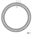
- the tube according to the invention comprises a middle layer 1, to which a first reinforcing layer 2 adjoins radially outward and a second reinforcing layer 3 radially inward.
- the two reinforcing layers 2 and 3 are thus spaced by the middle layer 1.
- an outer layer 4 Radially inner, an inner layer 5 may be applied.
- the tube according to the invention is thus formed at least three layers, in a preferred embodiment five layers.
- the embodiment relates to a five-layer design with outer layer 4 and inner layer 5. However, these are not essential to the inventive idea, so that the embodiment is not limiting.
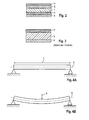
- the Fig. 2 again shows a sectional view, from which results the layer structure according to the invention. This clarifies the difference with the prior art, which in Fig. 3 is shown.
- a very thick middle layer 6 is formed, which makes up the actual tube volume and which is covered by a relatively thin outer layer 7 and a relatively thin inner layer 8.
- the outer layer 7 and the inner layer 8 are essentially not the reinforcement or stiffening, but only the functional performance in terms of chemical resistance, gas tightness, fluid tightness, mechanical strength, etc.
- the Fig. 4 shows in the illustration the position of the neutral fiber X, which extends in the longitudinal direction L of the tube.
- the neutral fiber When a force F is applied, the neutral fiber remains essentially neutral, it is not stretched and thus does not contribute to the strength or rigidity of the pipe with regard to the construction described according to the invention. It can be seen that the two reinforcing layers spaced apart by the middle layer disposed in the neutral fiber effect reinforcement and stiffening of the tube.
- the bending stiffness of the plastic pipe according to the invention can be increased by more than 20% compared to the prior art.
- the total pipe thickness or the total amount of reinforcing materials need not be increased for this purpose.
- the invention is not limited to simple tubes, but also tube elements, such as elbows, branch element or the like can be formed in accordance with the invention.
- the bending stiffness of the composite results from the sum of the bending stiffness, which in turn represents the product of moment of inertia and modulus of elasticity.
Landscapes
- Engineering & Computer Science (AREA)
- General Engineering & Computer Science (AREA)
- Mechanical Engineering (AREA)
- Rigid Pipes And Flexible Pipes (AREA)
- Laminated Bodies (AREA)
Abstract
Description
- Die Erfindung bezieht sich auf ein mehrschichtiges Kunststoffrohr. Im Einzelnen bezieht sich die Erfindung auf ein Kunststoffrohr, welches mehrlagig ausgebildet und mit zumindest einer Verstärkungsschicht versehen ist.
- Aus dem Stand der Technik ist es bekannt, bei Kunststoffrohren, welche beispielsweise extrudiert oder spritzgegossen sind, eine faserverstärkte Schicht vorzusehen. So zeigt beispielsweise die
DE 10 2004 010 340 B4 ein Kunststoffrohr, welches dreischichtig aufgebaut ist. Zwischen einer Außenschicht und einer Innenschicht ist eine faserverstärkte Schicht angeordnet. Eine ähnliche Konstruktion zeigen auch dieDE 100 18 324 C2 oder dieDE 10 2007 035 657 A1 . - Allgemein weisen die aus dem Stand der Technik bekannten Kunststoffrohre eine hohe chemische Beständigkeit auf, sie besitzen jedoch den Nachteil einer im Vergleich zu Metallen geringen Eigensteifigkeit und einer großen Längenausdehnung unter Temperatureinfluss. Aus diesem Grunde hat man im Stand der Technik vorgeschlagen, den Kern des Rohres mit Fasern zu verstärken, um diese Nachteile auszugleichen. Der die Mittelschicht bildende Kern ist dann mit einer Innenschicht und einer Außenschicht belegt, die beispielsweise einen UV-Schutz gewährleistet, eine ausreichende mechanische Festigkeit aufweist oder gegen die durchzuleitenden Medien resistent ist.
- Es hat sich in der Praxis jedoch gezeigt, dass eine Faserverstärkung des Kerns des Rohres die Steifigkeit des Rohres nur unwesentlich erhöht. Dieses neigt bei Belastung (Fluidfüllung) weiterhin zur Durchbiegung und erfordert somit, insbesondere bei einer horizontalen Montage, eine Vielzahl von Befestigungspunkten.
- Aus der
AT 316 228 B - Die
AT 360 286 B - Der Erfindung liegt die Aufgabe zugrunde, ein Kunststoffrohr der eingangs genannten Art zu schaffen, welches bei einfachem Aufbau und einfacher, kostengünstiger Herstellbarkeit eine hohe Verformungsbeständigkeit aufweist.
- Erfindungsgemäß wird die Aufgabe durch die Merkmalskombination des Anspruchs 1 gelöst, die Unteransprüche zeigen weitere vorteilhafte Ausgestaltungen der Erfindung.
- Erfindungsgemäß ist somit vorgesehen, nicht den Kern des aus einem thermoplastischen Material gefertigten Rohres zu verstärken, sondern diesen unverstärkt zu lassen. Der Kern des Rohres, welcher in der neutralen Faser liegt, wird somit nicht verstärkt und kann aus einem üblichen Material, beispielsweise einem Polymer, gefertigt werden. Angrenzend an diese Mittelschicht weist das erfindungsgemäße Kunststoffrohr jeweils eine faserverstärkte Schicht auf. Diese Verstärkungsschichten liegen somit außerhalb der neutralen Faser und sind hinsichtlich der axialen Stabilität des Kunststoffrohrs besonders wirksam. Die Verstärkungsschichten wirken somit einer Durchbiegung des Rohres bei Füllung mit Fluid wirkungsvoll entgegen. Die Verstärkung erfolgt erfindungsgemäß mittels Kurzfasern, welche in das Material der Verstärkungsschicht eingebettet sind. Das erfindungsgemäße Rohr wird mittels eines Extrusionsprozesses koextrudiert.
- Erfindungsgemäß ist vorgesehen, dass die beiden Verstärkungsschichten mit einer Außenschicht bzw. einer Innenschicht abgedeckt werden können, welche chemisch resistent sind, welche mit Additiven versehen sein können und welche die ausreichenden mechanischen Festigkeitswerte aufweisen können.
- Das erfindungsgemäße Rohr zeichnet sich durch eine Reihe erheblicher Vorteile aus.
- Das Kunststoffrohr ist insbesondere im Leitungsbereich für Gase und Flüssigkeiten besonders vorteilhaft einsetzbar und ist insbesondere auch überputz montierbar, da die große Festigkeit gegen Durchbiegung und die große Kriechfestigkeit nur eine relativ geringe Anzahl an Befestigungen (Befestigungspunkten) erfordern. Der axiale Durchhang ist somit weitgehend vermieden, das erfindungsgemäße Kunststoffrohr ist sehr steif und weist ein hohes Trägheitsmoment auf.
- Erfindungsgemäß ist es möglich, die beiden Verstärkungsschichten mit üblichen Mineral- oder Kurzglasfaserverstärkungen zu versehen.
- Weiterhin erweist es sich als vorteilhaft, dass die Dicken der beiden Verstärkungsschichten nur sehr gering sein brauchen, so dass das erfindungsgemäße Kunststoffrohr sehr kostengünstig herstellbar ist.
- Bei Betrachtung eines inkrementellen Teils des Rohres ergibt sich somit eine starke Erhöhung der Steifigkeit bei Einsatz einer minimalen Menge an Verstärkungsmaterialien.
- Erfindungsgemäß ist die Mittelschicht bevorzugterweise im Bereich der neutralen Faser des Rohres angeordnet und/oder parallel zur neutralen Faser ausgerichtet.
- Die Verstärkungsmaterialien sind bevorzugterweise in einem Anteil von kleiner als 30 Gew.-% des Gesamtgewichts des Rohres vorhanden. Dies führt zu einer erheblichen Kostensenkung und Gewichtsreduzierung, insbesondere im Vergleich mit den aus dem Stand der Technik bekannten Konstruktionen, bei denen der Faseranteil der verstärkten Mittelschicht 55 bis 75 Gew.-%, entsprechend 30 bis 50 Vol.-%, betragen kann.
- Erfindungsgemäß kann die Dicke der Mittelschicht des Rohres zwischen 10 und 70 % der Gesamtdicke der Wandung des Rohres umfassen. Bei einem geringeren Anteil als 10 % kann keine ausreichende Beabstandung der Verstärkungsschichten erzielt werden, während ein höherer Anteil als 70 % zu wenig Dickenanteil für die Verstärkungsschichten zur Verfügung stellt. Vorteilhafterweise liegt der Dickenanteil der Mittelschicht zwischen 20 und 40 % der Gesamtdicke der Rohrwandung.
- Als Verstärkungsmaterialien werden bevorzugter Weise Kurzglasfasern mit einer Länge zwischen 3 mm und 5 mm eingesetzt. Bei einer Aufbringung der Faserschichten im Koextrusionsprozess, werden die Fasern nur minimal in Extrusionsrichtung orientiert. Durch die großteils ungerichtete Faserverteilung, wird das Rohr nicht nur axial, sondern auch am Umfang verstärkt. Diese Umfangsverstärkung erhöht die Ringsteifigkeit wesentlich, wodurch der Widerstand des Rohres gegenüber radialen Verformungen wesentlich erhöht wird.
- In günstiger Weiterbildung der Erfindung kann vorgesehen werden, dass zwischen den einzelnen Schichten oder zwischen einzelnen der Schichten des Rohres ein Haftvermittler vorgesehen ist. Weiterhin kann es günstig sein, wenn eine vorhandene Außenschicht oder Innenschicht mit Additiven versehen oder mit Ausrüstungen ausgestattet ist, welche die Gas- oder Fluiddichtigkeit, die Umweltresistenz, die mechanischen Festigkeitswerte und/oder das optische Erscheinungsbild verbessert. Derartige Funktionsadditive oder Funktionen sind aus dem Stand der Technik bekannt. Sie können weiterhin Barriereeigenschaften, Flammschutz, Hygieneanforderungen hinsichtlich Mikroorganismen oder optische Eigenschaften hinsichtlich der Kennzeichnung haben.
- Erfindungsgemäß können als Basispolymer für die einzelnen Schichten gleiche, aber auch unterschiedliche Kunststoffe verwendet werden. Diese stammen vorzugsweise aus der Gruppe der Thermoplaste. Innerhalb der einzelnen Werkstoffgruppen der Schichten können gleiche oder unterschiedliche Werkstoffe verwendet werden. Polymere, die besonders zur Verwendung bei dem erfindungsgemäßen Kunststoffrohr geeignet sind, sind PP, HDPE, LDPE, PVC, ABS oder PA.
- Neben verschiedenen Basispolymeren können für die Verstärkungsschichten gleiche oder andere Basispolymere gewählt werden, ebenso sind verschiedene Verstärkungsstoffe in vorteilhafter Weise einsetzbar.
- Die beiden Verstärkungsschichten können erfindungsgemäß die gleichen, aber auch unterschiedliche Verstärkungsmaterialien in der Kunststoffmatrix aufweisen. Als Verstärkungsstoffe sind beispielsweise kurzfaserförmige Verstärkungsstoffe wie Glasfasern, Kohlefasern, Aramidfasern oder Naturfasern, wie etwa Flachs, vorteilhaft.
- Weiter ist es erfindungsgemäß möglich, einzelne der Schichten, vorzugsweise jedoch die Mittelschicht geschäumt auszuführen, um zusätzlich Material und Gewicht zu sparen und die Kosten zu senken.
- Durch Vernetzen der Kunststoffe in einer oder mehreren Schichten des Rohres können die Eigenschaften, insbesondere hinsichtlich der Festigkeit und Temperaturtestbeständigkeit verbessert werden.
- Durch das Einbringen von metallischen Partikeln oder Partikeln, die durch ein induktives Feld mit Temperaturerhöhung reagieren, ist es möglich, das Rohr mit Kunststoffteilen zu verbinden, z. B. durch Schweißen.
- Im Folgenden wird die Erfindung anhand eines Ausführungsbeispiels in Verbindung mit der Zeichnung beschrieben. Dabei zeigt:
- Fig. 1
- eine Radial-Schnittansicht eines erfindungsgemäßen Rohres,
- Fig. 2
- eine Teil-Schnittansicht als inkrementelles Rohrstück,
- Fig. 3
- eine Ansicht, analog
Fig. 2 , eines Aufbaus gemäß dem Stand der Technik, und - Fig. 4
- eine Darstellung der Mechanik der Biegefestigkeit und der neutralen Faser.
- Das erfindungsgemäße Rohr umfasst eine Mittelschicht 1, an welche sich radial außenliegend eine erste Verstärkungsschicht 2 und radial innenliegend eine zweite Verstärkungsschicht 3 anschließen. Die beiden Verstärkungsschichten 2 und 3 sind somit durch die Mittelschicht 1 beabstandet. Radial außen kann eine Außenschicht 4, radial innen kann eine Innenschicht 5 aufgebracht sein. Das erfindungsgemäße Rohr ist somit zumindest dreilagig, in bevorzugter Weiterbildung fünflagig ausgebildet. Das Ausführungsbeispiel bezieht sich auf eine fünflagige Ausgestaltung mit Außenschicht 4 und Innenschicht 5. Diese sind jedoch für den Erfindungsgedanken nicht wesentlich, so dass das Ausführungsbeispiel nicht einschränkend ist.
- Es versteht sich, dass die dargestellten Dickenverhältnisse nur zu Zwecken der verdeutlichenden Darstellung gewählt wurden.
- Die
Fig. 2 zeigt nochmals eine Schnittdarstellung, aus welcher sich der erfindungsgemäße Schichtaufbau ergibt. Dies verdeutlicht den Unterschied zum Stand der Technik, der inFig. 3 dargestellt ist. Dort ist eine sehr dicke Mittelschicht 6 ausgebildet, die das eigentliche Rohrvolumen ausmacht und die durch eine relativ dünne Außenschicht 7 und eine relativ dünne Innenschicht 8 abgedeckt ist. Die Außenschicht 7 und die Innenschicht 8 dienen im Wesentlichen nicht der Verstärkung oder Versteifung, sondern lediglich der Funktionserfüllung hinsichtlich Chemikalienbeständigkeit, Gasdichtigkeit, Fluiddichtigkeit, mechanischer Festigkeit, etc. DieFig. 4 zeigt in der Verdeutlichung die Lage der neutralen Faser X, welche sich in Längsrichtung L des Rohres erstreckt. Bei Einwirkung einer Kraft F verbleibt die neutrale Faser im Wesentlichen neutral, sie wird nicht gedehnt und trägt somit im Hinblick auf die erfindungsgemäß beschriebene Konstruktion nichts zur Festigkeit oder Steifigkeit des Rohres bei. Hieraus wird deutlich, dass die beiden durch die in der neutralen Faser liegende Mittelschicht beabstandeten Verstärkungsschichten die Verstärkung und Versteifung des Rohres bewirken. - Durch die erfindungsgemäße Konstruktion kann die Biegesteifigkeit des erfindungsgemäßen Kunststoffrohrs im Vergleich zu Stand der Technik um mehr als 20 % erhöht werden. Die Gesamtrohrdicke bzw. die Gesamtmenge an Verstärkungsmaterialien brauchen hierfür nicht erhöht werden.
- Weiterhin ist die Erfindung nicht auf einfache Rohre beschränkt, vielmehr können auch Rohrelemente, wie Winkelstücke, Abzweigungselement oder Ähnliches in erfindungsgemäßer Weise ausgebildet werden.
- Insgesamt ergibt sich durch den erfindungsgemäßen Rohraufbau eine hohe Steifigkeit, bei gleichzeitig geringerem Einsatz von Verstärkungsmaterial. Die Verstärkungsschichten können erfindungsgemäß wirkungsvoll durch eine Außenschicht und/ oder eine Innenschicht geschützt werden.
- Im Folgenden wird rechnerisch ein Beispiel eines erfindungsgemäßen Rohres im Vergleich zum Stand der Technik in Verbindung mit den
Fig. 2 und 3 berechnet: - Breite: 50mm
- Gesamthöhe (entsprecht der Rohrwanddicke): 10mm
- (im Fall 1 (Stand der Technik It.
Figur 2 ) erfolgt die Aufteilung: - 2,5; 5 und 2,5mm Dicke der einzelnen Schichten;
- im Fall 2 (
Figur 3 ): 1,5; 2,5; 2,0; 2,5 und 1,5mm Schichtdicke) - E-Modul Kunststoffschichten: 1000 N/mm2
- E-Modul Verstärkungsschichten: 3000 N/mm2
- Die Biegesteifigkeit des Verbundes ergibt sich aus der Summe der Biegesteifigkeiten, welche wiederum das Produkt aus Trägheitsmoment und E-Modul darstellt.
- Beim Trägheitsmoment gilt für beabstandete Schichten der Satz von Steiner, wonach sich das Trägheitsmoment wie folgt errechnet:

E [N/mm2] I [mm4] Biegesteifigkeit [N mm2] b h a Schicht A 1 000,00 1 822,92 1 822 916,67 50 2,5 3,75 Schicht B 3 000,00 520,83 1 562 500,00 50 5 0 Schicht A 1 000,00 1 822,92 1 822 916,67 50 2,5 3,75 5 208 333,33 Schicht 21 1 000,00 1 368,75 1 368 750,00 50 1,5 4,25 Schicht 31 3000,00 697,92 2093750,00 50 2,5 2,25 Schicht 22 1 000,00 33,33 33333,33 50 2 0 Schicht 32 3000,00 697,92 2093750,00 50 2,5 2,25 Schicht 23 1 000,00 1 368,75 1 368 750,00 50 1,5 4,25 6 958 333,33 - Im ersten Fall ergibt sich für die Biegesteifigkeit: 5 208 333 Nmm2, im zweiten Fall mit einem erfindungsgemäßen Rohraufbau bei gleichem Materialeinsatz: 6 958 333 Nmm2, was einer Erhöhung um nahezu 35% entspricht.
Claims (12)
- Starres Kunststoffrohr aus thermoplastischem Material mit zumindest drei Schichten, wobei eine Mittelschicht (1) vorgesehen ist, an welcher zumindest eine radial außenliegende, mit Kurzfaser verstärkten Verstärkungsmaterialien verstärkte erste Verstärkungsschicht (2) und zumindest eine radial innenliegende, mit Kurzfaser verstärkten Verstärkungsmaterialien verstärkte zweite Verstärkungsschicht (3) angrenzen, wobei die thermoplastischen Verstärkungsschichten ungerichtete Fasern aufweisen und im Extrusionsprozess aufgebracht sind.
- Kunststoffrohr nach Anspruch 1, dadurch gekennzeichnet, dass die Mittelschicht (1) im Bereich der neutralen Faser des Rohrs angeordnet ist.
- Kunststoffrohr nach Anspruch 1 oder 2, dadurch gekennzeichnet, dass die Verstärkungsmaterialien in der ersten (2) und der zweiten (3) Verstärkungsschicht in einem Anteil von kleiner als 30 Gew.-% des Gesamtgewichts des Rohrs vorliegen.
- Kunststoffrohr nach einem der Ansprüche 1 bis 3, dadurch gekennzeichnet, dass die Dicke der Mittelschicht des Rohrs (10) bis 70 % der Gesamtdicke der Wandung des Rohrs umfasst.
- Kunststoffrohr nach einem der Ansprüche 1 bis 3, dadurch gekennzeichnet, dass die Dicke der Mittelschicht des Rohrs (10) bis 20 bis 40 % der Gesamtdicke der Wandung des Rohrs umfasst.
- Kunststoffrohr nach einem der Ansprüche 1 bis 5, dadurch gekennzeichnet, dass die Verstärkungsmaterialien faserförmig ausgebildet sind.
- Kunststoffrohr nach einem der Ansprüche 1 bis 6, dadurch gekennzeichnet, dass die Verstärkungsschichten von einer Deckschicht abgedeckt sind.
- Kunststoffrohr nach einem der Ansprüche 1 bis 7, dadurch gekennzeichnet, dass der Anteil der Verstärkungsmaterialien 10 bis 30 Gew.-% beträgt.
- Kunststoffrohr nach einem der Ansprüche 1 bis 8, dadurch gekennzeichnet, dass zwischen zumindest einzelnen der Schichten des Rohrs ein Haftvermittler vorgesehen ist.
- Kunststoffrohr nach einem der Ansprüche 1 bis 9, dadurch gekennzeichnet, dass zumindest eine der Schichten des Rohrs geschäumt ausgebildet ist.
- Kunststoffrohr nach einem der Ansprüche 1 bis 10, dadurch gekennzeichnet, dass ein gleiches Basispolymer für die Schichten verwendet wird.
- Kunststoffrohr nach einem der Ansprüche 1 bis 10, dadurch gekennzeichnet, dass ein unterschiedliches Basispolymer für die Schichten verwendet wird.
Applications Claiming Priority (1)
| Application Number | Priority Date | Filing Date | Title |
|---|---|---|---|
| DE102009014534 | 2009-03-24 |
Publications (2)
| Publication Number | Publication Date |
|---|---|
| EP2233811A2 true EP2233811A2 (de) | 2010-09-29 |
| EP2233811A3 EP2233811A3 (de) | 2011-05-25 |
Family
ID=42315357
Family Applications (1)
| Application Number | Title | Priority Date | Filing Date |
|---|---|---|---|
| EP10003156A Withdrawn EP2233811A3 (de) | 2009-03-24 | 2010-03-24 | Kunststoffrohr |
Country Status (1)
| Country | Link |
|---|---|
| EP (1) | EP2233811A3 (de) |
Cited By (7)
| Publication number | Priority date | Publication date | Assignee | Title |
|---|---|---|---|---|
| CN103307370A (zh) * | 2013-07-03 | 2013-09-18 | 南通市长海实业有限公司 | 一种新型玻璃钢管道 |
| WO2013137745A1 (en) * | 2012-03-14 | 2013-09-19 | Purapipe As | Multilayer pipeline in a polymer material, device for manufacture of the multilayer pipeline and a method for manufacturing the multilayer pipeline |
| CN103742732A (zh) * | 2013-12-24 | 2014-04-23 | 苏州市木易船舶设备有限公司 | 一种玻璃钢管道及其制造方法 |
| CN105221852A (zh) * | 2014-06-17 | 2016-01-06 | 齐克先 | 一种复合塑料管及制造连接方法 |
| CN112664724A (zh) * | 2020-12-24 | 2021-04-16 | 安徽杰蓝特新材料有限公司 | 一种连续碳纤维缠绕复合增强pe给水管材及其制备方法 |
| CN113910719A (zh) * | 2021-09-29 | 2022-01-11 | 湖北金牛管业有限公司 | 一种低回缩率pvc排水管及其制备方法 |
| CN114583650A (zh) * | 2022-03-03 | 2022-06-03 | 四川信固科技有限公司 | 一种增强型耐热复合电力管及其制备方法 |
Citations (5)
| Publication number | Priority date | Publication date | Assignee | Title |
|---|---|---|---|---|
| AT316228B (de) | 1970-10-15 | 1974-06-25 | Bayer Ag | Kunststoffrohr mit einer Faserarmierung und Verfahren und Vorrichtung zum kontinuierlichen Herstellen dieses Kunststoffrohres |
| AT360286B (de) | 1975-06-05 | 1980-12-29 | Bekaert Sa Nv | Schichtformkoerper |
| DE10018324C2 (de) | 2000-04-13 | 2003-03-27 | Gerhard Rosenberg | Extrudiertes, spritzgegossenes oder blasgeformtes Rohr, Fitting oder Formstück aus Kunststoff zum Erstellen von Rohrleitungen für flüssige, pastöse und gasförmige Medien |
| DE102004010340B4 (de) | 2004-03-03 | 2007-06-28 | Poloplast Gmbh | Kunststoffrohr mit Faserverstärkung |
| DE102007035657A1 (de) | 2006-08-03 | 2008-02-14 | Wefa Plastic Kunststoffverarbeitungs Gmbh | Rohr und/oder Verbindungsstück aus einem thermoplastischen Werksstoff |
Family Cites Families (4)
| Publication number | Priority date | Publication date | Assignee | Title |
|---|---|---|---|---|
| GB1177249A (en) * | 1966-03-11 | 1970-01-07 | Wavin Bv | Improvements in and relating to Polyvinyl Chloride Tubes |
| US4351364A (en) * | 1979-11-05 | 1982-09-28 | Dunlop Limited | Steel reinforced pipe |
| NO175550C (no) * | 1991-05-31 | 1997-05-02 | Compipe As | Fremgangsmåte ved fremstilling av laminatrör |
| FI100130B (fi) * | 1995-12-12 | 1997-09-30 | Uponor Innovation Ab | Monikerroksinen muoviputki |
-
2010
- 2010-03-24 EP EP10003156A patent/EP2233811A3/de not_active Withdrawn
Patent Citations (5)
| Publication number | Priority date | Publication date | Assignee | Title |
|---|---|---|---|---|
| AT316228B (de) | 1970-10-15 | 1974-06-25 | Bayer Ag | Kunststoffrohr mit einer Faserarmierung und Verfahren und Vorrichtung zum kontinuierlichen Herstellen dieses Kunststoffrohres |
| AT360286B (de) | 1975-06-05 | 1980-12-29 | Bekaert Sa Nv | Schichtformkoerper |
| DE10018324C2 (de) | 2000-04-13 | 2003-03-27 | Gerhard Rosenberg | Extrudiertes, spritzgegossenes oder blasgeformtes Rohr, Fitting oder Formstück aus Kunststoff zum Erstellen von Rohrleitungen für flüssige, pastöse und gasförmige Medien |
| DE102004010340B4 (de) | 2004-03-03 | 2007-06-28 | Poloplast Gmbh | Kunststoffrohr mit Faserverstärkung |
| DE102007035657A1 (de) | 2006-08-03 | 2008-02-14 | Wefa Plastic Kunststoffverarbeitungs Gmbh | Rohr und/oder Verbindungsstück aus einem thermoplastischen Werksstoff |
Cited By (12)
| Publication number | Priority date | Publication date | Assignee | Title |
|---|---|---|---|---|
| WO2013137745A1 (en) * | 2012-03-14 | 2013-09-19 | Purapipe As | Multilayer pipeline in a polymer material, device for manufacture of the multilayer pipeline and a method for manufacturing the multilayer pipeline |
| CN104334950A (zh) * | 2012-03-14 | 2015-02-04 | 皮派克控股有限公司 | 聚合物材料制成的多层管道、用于制造多层管道的装置和用于制造多层管道的方法 |
| CN104334950B (zh) * | 2012-03-14 | 2016-05-11 | 皮派克控股有限公司 | 环形多层管道、制造管道的机器组件及形成管道的方法 |
| EA028688B1 (ru) * | 2012-03-14 | 2017-12-29 | Пьюрэпайп Холдинг Лтд. | Многослойный полимерный трубопровод, устройство и способ изготовления такого многослойного трубопровода |
| CN103307370A (zh) * | 2013-07-03 | 2013-09-18 | 南通市长海实业有限公司 | 一种新型玻璃钢管道 |
| CN103742732A (zh) * | 2013-12-24 | 2014-04-23 | 苏州市木易船舶设备有限公司 | 一种玻璃钢管道及其制造方法 |
| CN103742732B (zh) * | 2013-12-24 | 2016-02-10 | 苏州市木易船舶设备有限公司 | 一种玻璃钢管道的制造方法 |
| CN105221852A (zh) * | 2014-06-17 | 2016-01-06 | 齐克先 | 一种复合塑料管及制造连接方法 |
| CN112664724A (zh) * | 2020-12-24 | 2021-04-16 | 安徽杰蓝特新材料有限公司 | 一种连续碳纤维缠绕复合增强pe给水管材及其制备方法 |
| CN112664724B (zh) * | 2020-12-24 | 2022-06-14 | 安徽杰蓝特新材料有限公司 | 一种连续碳纤维缠绕复合增强pe给水管材及其制备方法 |
| CN113910719A (zh) * | 2021-09-29 | 2022-01-11 | 湖北金牛管业有限公司 | 一种低回缩率pvc排水管及其制备方法 |
| CN114583650A (zh) * | 2022-03-03 | 2022-06-03 | 四川信固科技有限公司 | 一种增强型耐热复合电力管及其制备方法 |
Also Published As
| Publication number | Publication date |
|---|---|
| EP2233811A3 (de) | 2011-05-25 |
Similar Documents
| Publication | Publication Date | Title |
|---|---|---|
| EP2233811A2 (de) | Kunststoffrohr | |
| DE102013109362B4 (de) | Kunststoffschlauch mit Gewebeverstärkung | |
| DE8324715U1 (de) | Rohrfoermiger hohlkoerper, insbesondere zur uebertragung von druck-, zug-, biege- und verdrehkraeften in fahrzeugen | |
| DE102013209097A1 (de) | Baugruppe in Faserverbundbauweise für ein Kraftfahrzeug | |
| DE19508193C2 (de) | Rohrförmiges Bauteil oder Hohlprofil mit besonderen Festigkeitseigenschaften bei geringem Gewicht sowie Verfahren zu seiner Herstellung | |
| DE3513267A1 (de) | Hydraulikbremsschlauch | |
| WO2010022927A1 (de) | Hochdruckbehälter | |
| DE2062418C3 (de) | Saugschlauch und Verfahren zu seiner Herstellung | |
| DE4430502A1 (de) | Verwendung eines Verbundaggregates aus einem Liner und einem faserverstärkten Kunststoffrohr als Druckzylinder eines Stelltriebes der Hochdruckhydraulik | |
| DE202009003662U1 (de) | Krafteinteilung in ein faserverstärktes Rohr | |
| DE202019101108U1 (de) | Mehrschichtverbundrohr | |
| DE102013008810B4 (de) | Krafteinleitung in Faserverbundrohre | |
| EP0982505B1 (de) | Seilhülle für Bowdenzüge | |
| EP3774304A1 (de) | Verfahren zur herstellung eines thermoplastischen strangprofils | |
| DE3337863C2 (de) | ||
| EP1418375B1 (de) | Mehrschichtiger flexibler Schlauch | |
| DE102021108564A1 (de) | Bauteil eines Kraftfahrzeugs | |
| AT17855U1 (de) | Thermisch Gedämmtes Rohr | |
| DE102007062326B4 (de) | Ladeboden für ein Kraftfahrzeug | |
| DE102015225823A1 (de) | Gleitlagerbuchse und Verfahren zur Herstellung der Gleitlagerbuchse | |
| DE2546737A1 (de) | Schutzschlauch fuer lichtleitkabel | |
| DE2854570A1 (de) | Verbundschlauch | |
| DE102017003024A1 (de) | Abschlusselement zur Krafteinleitung in ein vorgefertigtes Faserkunststoffverbundrohr | |
| DE102014019152A1 (de) | Profilteil sowie Verfahren zur Herstellung eines Profilteils | |
| DE20318129U1 (de) | Tankkonsole aus faserverstärktem Thermoplast |
Legal Events
| Date | Code | Title | Description |
|---|---|---|---|
| PUAI | Public reference made under article 153(3) epc to a published international application that has entered the european phase |
Free format text: ORIGINAL CODE: 0009012 |
|
| AK | Designated contracting states |
Kind code of ref document: A2 Designated state(s): AT BE BG CH CY CZ DE DK EE ES FI FR GB GR HR HU IE IS IT LI LT LU LV MC MK MT NL NO PL PT RO SE SI SK SM TR |
|
| AX | Request for extension of the european patent |
Extension state: AL BA ME RS |
|
| PUAL | Search report despatched |
Free format text: ORIGINAL CODE: 0009013 |
|
| AK | Designated contracting states |
Kind code of ref document: A3 Designated state(s): AT BE BG CH CY CZ DE DK EE ES FI FR GB GR HR HU IE IS IT LI LT LU LV MC MK MT NL NO PL PT RO SE SI SK SM TR |
|
| AX | Request for extension of the european patent |
Extension state: AL BA ME RS |
|
| STAA | Information on the status of an ep patent application or granted ep patent |
Free format text: STATUS: THE APPLICATION IS DEEMED TO BE WITHDRAWN |
|
| 18D | Application deemed to be withdrawn |
Effective date: 20111126 |