EP2233054A2 - Aspirateur doté d'un élément de liaison - Google Patents
Aspirateur doté d'un élément de liaison Download PDFInfo
- Publication number
- EP2233054A2 EP2233054A2 EP10154610A EP10154610A EP2233054A2 EP 2233054 A2 EP2233054 A2 EP 2233054A2 EP 10154610 A EP10154610 A EP 10154610A EP 10154610 A EP10154610 A EP 10154610A EP 2233054 A2 EP2233054 A2 EP 2233054A2
- Authority
- EP
- European Patent Office
- Prior art keywords
- joint
- vacuum cleaner
- connecting element
- advantageously
- hose
- Prior art date
- Legal status (The legal status is an assumption and is not a legal conclusion. Google has not performed a legal analysis and makes no representation as to the accuracy of the status listed.)
- Granted
Links
Images


Classifications
-
- A—HUMAN NECESSITIES
- A47—FURNITURE; DOMESTIC ARTICLES OR APPLIANCES; COFFEE MILLS; SPICE MILLS; SUCTION CLEANERS IN GENERAL
- A47L—DOMESTIC WASHING OR CLEANING; SUCTION CLEANERS IN GENERAL
- A47L9/00—Details or accessories of suction cleaners, e.g. mechanical means for controlling the suction or for effecting pulsating action; Storing devices specially adapted to suction cleaners or parts thereof; Carrying-vehicles specially adapted for suction cleaners
- A47L9/24—Hoses or pipes; Hose or pipe couplings
- A47L9/242—Hose or pipe couplings
Definitions
- the present invention relates to a vacuum cleaner with a connecting element, wherein the connecting element comprises a first and a second pipe piece, which are connected via a pivotable joint and which are connected via an air duct.
- the DE 199 07 051 A1 known which discloses a cleaning device, in particular a floor cleaning device, on the housing a for forwarding a stained medium, in particular air, serving hose is connected by means of a rotatable mounted in a housing suction on the coupling element and the coupling element is mounted like a ball joint in the suction , whereby a pivoting of the suction hose in all directions is made possible.
- a disadvantage of such a ball joint-like arrangement may be that the outlet-side end piece moves with the ball joint-like coupling element and thereby creates a positionally variable coupling point to a Staubabscheideech.
- connection element for a mouthpiece which provides a flexible connection from a nozzle sole to a subsequent suction tube via a flexible suction hose, wherein the connection provides a change in angle of the suction tube to the vacuum cleaner mouthpiece, wherein a given change in angle of the suction tube over its longitudinal centerline a substantially causes evenly large angular change of the mouthpiece.
- a disadvantage of such an arrangement may be that the flexible connection builds up relatively high, and the flexible suction hose for guiding the suction air in the handling of external objects can be damaged.
- a nozzle for a canister vacuum cleaner with a suction head wherein the suction head discloses a mouth opening into the suction mouth, a pipe socket for connection of a suction tube and a joint between the pipe socket and the suction head, which contains the suction channel, wherein the joint is designed as a universal joint , which has two pivotally connected to a hinge axis channel sections, wherein a channel portion is used as Saugkopfan gleichelement about a hinge axis orthogonal to the hinge axis tiltable in the suction head and wherein the second channel portion of the universal joint is inserted into the Saugkopfan gleichelement so that the lines of action of the hinge axis and to intersect the orthogonal axis.
- a disadvantage of such a nozzle may be that particularly elongated dust particles, such as. B. fibers or hair can accumulate between the moving joint parts and can block the passage opening.
- Another disadvantage may be that different flow conditions may arise due to the movable connection elements depending on the existing deflection on the intake duct.
- the invention has the object of developing an improved vacuum cleaner with a connecting element of the type described in more detail so that in particular disadvantages of said connecting elements can be overcome.
- a connecting element is to be provided, which returns after a successful deflection back to its original position and retains until a further force on the connecting element.
- a vacuum cleaner with electrical energy powered devices to absorb dust are understood, including both mains-powered and battery or cordless devices, and stationary suction systems are included.
- upstream dust collecting devices can be used on the Saugluft Unit.
- a pipe section is to be understood a tube of any length, wherein the length may also be smaller than the inner diameter.
- a ring can be referred to as a piece of pipe.
- the axis of a pipe is meant a straight line which extends in the length of the pipe and which intersects the pipe cross-sectional area in its center of gravity.
- the component of the connecting element can be understood, which can direct the dust-laden suction air, which may also be moist, from the first to the second pipe section.
- the suction air can be guided bidirectionally through the connecting element, ie from the first to the second or from the second to the first pipe section.
- the air duct can be advantageously realized by structural measures, such as by a housing or a hose, wherein the air can be passed from one piece of pipe to the other.
- a particular advantage may be distinguished if escape through the air duct between the two pipe sections no part of the air, and / or no additional air can flow.
- the air can be guided, for example, from the first pipe section to the second pipe section. Under a joint is an element to understand that has a defined pivot point or at least one defined axis of rotation.
- the first and the second pipe section are connected to each other via a pivotable joint.
- the first and the second pipe piece are each connected to the joint.
- the pivotable joint allows tilting of the two pipe pieces to each other, wherein the two pipe pieces are not to be removed from each other.
- the tilting can advantageously take place in different directions, and can be compared with the mobility of a joystick.
- the joint may consist of at least consist of a hinge part, so that the pipe pieces can be advantageously connected via at least one pivotable hinge part.
- the first and the second pipe section are connected to each other via an air duct.
- an airtight joint designed to connect the first and the second tube piece both as a joint and as an air guide.
- a separate air guide can advantageously prevent contamination of the joint, and allow a simpler construction of the joint, which can also lead to lower production costs.
- the developer of the connecting element can thus advantageously decide which embodiment can be preferred in terms of cost, manufacturing or assembly methods.
- the connecting element according to the invention can lead to an improvement in the service characteristics of a vacuum cleaner, for example by increasing the flexibility of a suction air duct or by improving the caster behavior of the vacuum cleaner housing of a canister vacuum cleaner.
- advantageously a kinking of the suction hose and thereby an unnecessary reduction in suction power can be prevented.
- the return means in a position outside the preferred position of the joint exerts a restoring force on the joint to bring the joint from any position in the preferred position.
- the force can advantageously also be exerted indirectly by the restoring device on the joint, for example, when the restoring device acts on one of the two pieces of pipe, which are particularly preferably connected in each case to the joint.
- Under preferred position is a special position of the two pipe pieces to each other to understand that advantageously without the action of external forces of the Connecting element is taken.
- the preferred position can be selected by constructive means so that a robust or convenient for the user arrangement of the vacuum cleaner can be provided. In addition, a visually pleasing vacuum cleaner can be made possible.
- the restoring device is an elastically deformable element.
- energy storage such as coil springs or gas springs to understand.
- simple or inexpensive components available on the market can be used.
- Another advantage may be that the restoring force can be adjusted by spring forces.
- the joint consists of at least a first and a second joint part.
- the joint parts can be pivoted.
- the joint is a ball joint, which may for example consist of a hollow ball as a first joint part and a holder as a second joint part, wherein the hollow ball can be kept undercut from the holder.
- the first joint part of this ball joint may be formed as a hollow ball segment.
- the joint consists of offset cylinder bodies, which are hollow.
- the hollow sphere or the hollow sphere segment can be removed, for example, only by disassembling the joint, since this is advantageously held in a form-fitting manner by the undercut holder.
- a cross-joint piece connects the first and the second hinge part.
- a joint provided with a universal joint may also be referred to as a universal joint.
- pivot pins are arranged on the cross-joint piece, which can enable a pivotable connection of the cross-joint piece about at least one axis with at least one of the joint parts.
- two pivot pins are arranged on the universal joint piece for two offset by 90 ° axes of rotation, on each of which the first and the second hinge part can be arranged rotatably mounted.
- two axes of rotation allow pivoting in different directions.
- the two axes of rotation are arranged in one plane.
- the first and the second hinge part are designed as a spherical cap, which are interconnected by the cross-joint piece via two offset by 90 ° axes of rotation.
- the joint or the air duct can be protected by the spherical cap from external influences, such as, for example, when being hit against objects during the vacuum cleaner operation.
- a visually pleasing design can be achieved.
- the axes of the two pipe sections can be deflected by a maximum of 45 °, ideally by 20 ° from each other.
- the universal joint can have a higher mechanical stability than a ball joint, and thus allow higher tensile loads. Further advantages of a universal joint can be the defined axes of rotation, simple manufacture and assembly, for example via snap connections. Advantageously, a universal joint with higher mechanical stability allow a comparable to a ball joint pivoting.
- At least one of the restoring devices is arranged at least on one of the joint parts.
- the restoring force can continue to attack away from a pivot point or a rotation axis, and thereby achieve a higher lever arm and less effort to return to the preferred position.
- the force can advantageously be introduced directly to the hinges.
- at least one of the restoring devices is arranged at least on one of the joint parts and at least on one of the pipe sections. It can be advantageously achieved that the restoring device can be further fixed to the connecting element, and thus a durable unit can be made possible.
- the air guide which connects the first and a second pipe piece with each other, a hose.
- a hose allow a flexible air flow with approximately constant flow cross-section.
- the hose can protect moving parts of the joint from dust, since they can be arranged in dust-free space outside the hose.
- the air flow through joint parts getting produced.
- the movable joint parts are provided with sealing elements, so as to advantageously provide a dense air flow at different positions of the joint.
- the hose has at least one of the return devices.
- the return element is a spring which is incorporated in the hose.
- such hoses are available on the market as a stretch tube or spring tube with different spring properties, and can therefore represent a cost-effective and simple alternative to a self-developed component.
- the spring may also be applied externally to the hose separately.
- two components can be integrated in one, which can lead to lower costs or a simpler installation.
- the first pipe section is preferably connected to the first joint part and the second pipe section is connected to the second joint part.
- this can reduce the number of components and the production, for example by injection molding, can be simplified, whereby the manufacturing cost can be reduced.
- the assembly of the connecting element can be advantageously simplified.
- a hose nozzle can be coupled to the first piece of pipe. Under a hose nozzle is the connection part at one end of a suction hose to understand.
- a releasable air guide connection can be produced thereby.
- the hose nozzle is endlessly rotatable in the pipe section.
- this can be a confinement due to movements of the suction hose are avoided during suction.
- this advantageously a higher mobility of the suction hose can be achieved.
- the hose nozzle can be firmly connected to the pipe section. Since this is no longer rotatably mounted, advantageously a very cheap and stable component can be made possible.
- a Staubabscheidetician can be coupled to the second pipe section.
- the pipe section is sealingly connectable to the Staubabscheidetician.
- the air duct connection to the dust separation unit can be released in order to be able to remove, for example, the dust removal unit for disposal of the dust.
- the connecting element is arranged on a vacuum cleaner housing of the vacuum cleaner.
- the connecting element is molded, welded or screwed.
- a connecting element may be arranged in the suction air guide of the vacuum cleaner.
- a suction air duct of a vacuum cleaner may comprise, for example, a vacuum cleaner nozzle, a telescopic vacuum cleaner pipe consisting of two plug pipes, a handle and a suction hose.
- the connecting element is arranged, for example, on the vacuum cleaner nozzle, between the handle and the suction pipe, between the handle and the suction hose or between two plug-and-socket pipes.
- the flexibility of the suction air duct can be increased by the connecting element.
- Inaccessible places, for example when sucking around furniture edges, can advantageously be better achieved, or a kinking of the suction hose can be advantageously prevented.
- the vacuum cleaner has two or more connecting elements, which are arranged for example on the vacuum cleaner housing and on the suction air.
- the connecting element is an exchangeable structural unit.
- the connecting element can be easily replaced in case of damage.
- a further preferred embodiment fall in the preferred position of the joint, the two axes of the pipe pieces to each other.
- the axis of a pipe is to be understood as a straight line which extends in the length of the pipe and which intersects the circular pipe cross-section in the center of the circle.
- a streamlined position of the air duct can be achieved. The user can In this position, for example, connect the suction hose particularly easily to the device. If the connecting element in the Saugluft arrangement mounted, this position corresponds to the position of the Saugluft arrangement without the connecting element, and thus advantageously allows normal operation.
- a visually pleasing suction air guide can be provided by this preferred position.
- the present invention makes it possible, with simple constructive and cost-effective means, to facilitate the follow-up behavior of a vacuum cleaner and can avoid unnecessary reduction in suction power due to angled suction air ducts in the region of the connecting element. Furthermore, a visually pleasing, robust and largely dirt-resistant suction air guide can be provided.
- a connecting element 2 is arranged on a vacuum cleaner housing 11 of a vacuum cleaner 1.
- the connecting element 2 comprises a first 3 and a second pipe section 4, a pivotable joint with a first 5 and a second joint part 6 and a resetting device designed as a helical spring 13.
- the first 3 and the second pipe section 4 are connected to each other via the pivotable joint and an air duct.
- the pivotable joint is designed as a ball joint, wherein the first joint part 5 is designed as a hollow ball and the second joint part 6 as a holder for the hollow sphere.
- the first joint part 5, ie the hollow sphere is undercut by the second joint part 6, that is to say the holder, whereby a positive connection is achieved.
- a pivot point 14 sets, which is located in the center of the hollow sphere.
- the preferred position is in Fig. 1 shown.
- the coil spring 13, an elastically deformable member, is attached to the second pipe section 4 and the vacuum cleaner housing 11 and exerts in a position outside the in Fig. 1 illustrated preferred position a restoring force on the joint in order to bring this in the preferred position.
- the air duct is taken over by the first joint part 5, to which the first 3 and the second pipe section 4 are attached.
- a hose nozzle 9 can be coupled in order to produce an air guide connection to a suction hose 15 can.
- a connection part which is located at one end of a suction hose 15 to understand.
- the connection between the hose nozzle 9 and the first pipe section 3 can be solved by a mechanism, not shown.
- a Staubabscheidetician 10 can be coupled, whereby an air guide connection between the suction hose 15 and a Staubabscheidetician 10 can be made.
- FIG. 2 shows an exploded view of the connecting element 2 of a vacuum cleaner 1.
- Fig. 3 is a section through the connecting element 2 from Fig. 2 along the auxiliary plane A shown.
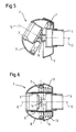
- a section along the line BB 'from Fig. 3 shows the connecting element 2 in Fig. 4 in preferred position of the joint.
- Fig. 5 the connecting element 2 is shown in the same view in a position outside the preferred position of the joint.
- the connecting element 2 is also arranged in the second embodiment on a vacuum cleaner housing 11 of a vacuum cleaner 1 and comprises a first 3 and a second pipe section 4, a pivotable joint which connects the two pipe sections together and a return device.
- a hose nozzle 9 is connected to the first pipe section 3, and to the second pipe section 4, a Staubabscheideech 10 can be coupled.
- the joint of the second embodiment is designed as a universal joint, and has a first 5 and a second joint part 6 and a cross-joint piece 7, which connects the first 5 and the second joint part 6.
- first joint part 5 is connected to the first pipe section 3 via a snap connection
- second joint part 6 is connected to the second pipe section 4, wherein the second joint part 6 and the second pipe section 4 form a component.
- the first 5 and the second joint part 6 are designed as a spherical cap and can thus protect the universal joint 7, for example against external influences such as shocks.
- a visually pleasing design is achieved.
- two pivot pins 17 are arranged for two offset by 90 ° axes of rotation 17, on each of which the first 5 and the second joint part 6 are rotatably mounted.
- the two axes of rotation 16 of the joint allow the pivoting of the two pipe sections 3, 4th in any direction that corresponds to the movement of the ball joint of the first embodiment about the pivot point 14.
- the first pipe section 3 and the second pipe section 4 are connected via an air guide, which is designed as a hose 8.
- the hose 8 off Fig. 2 and 4 is not in for illustrative purposes Fig. 5 shown, and allows for different positions of the joint a flexible air flow with approximately constant flow cross-section. In addition, moving parts of the joint, in particular the pivot pin 17, are protected from dust.
- the hose 8 has the return device, which is designed as a spring, an elastically deformable element.
- the spring is molded into the tube and is not shown for purposes of illustration. Outside the preferred position of the joint, the spring exerts a force on the joint to bring the joint from any position to the preferred position.
- the axes 12 of the two pipe sections 3, 4 by 30 °, as in Fig. 5 represented, are deflected from each other.
- the preferred position of the joint is characterized in that the two axes 12 of the pipe sections 3, 4 fall on each other, whereby a flow-favorable position of the tube 8, ie the air duct, is achieved.
- a restoring device designed as a helical spring 13 is arranged on the first joint part 5 and the cross-joint piece 7. Since the force exerted by the spring on the hinge restoring force acts further away from a rotation axis 16, thereby a higher lever arm and thus a lower force to return to the preferred position can be achieved.
- a vacuum cleaner 1 comprises a connecting element 2 which is arranged in a suction air guide 18.
- the connecting element 2 may correspond to one of the connecting elements 2 from the first, second or third embodiment.
- the suction air duct 18 has, in addition to the connecting element 2, a vacuum cleaner nozzle 19, a suction pipe 20, a handle 21 and a suction hose 15, the connecting element 2 being arranged between the handle 21 and the suction hose 15.
- the flexibility of the suction air guide 18 can be increased in order to better reach, for example, hard to reach places.
- the present invention makes it possible, with simple constructive and cost-effective means, to facilitate the follow-up behavior of a vacuum cleaner and can avoid unnecessary reduction in suction power due to angled suction air ducts in the region of the connecting element. Furthermore, a visually pleasing, robust and largely dirt-resistant suction air guide can be provided.
Landscapes
- Engineering & Computer Science (AREA)
- Mechanical Engineering (AREA)
- Electric Vacuum Cleaner (AREA)
Applications Claiming Priority (1)
| Application Number | Priority Date | Filing Date | Title |
|---|---|---|---|
| DE200910001881 DE102009001881A1 (de) | 2009-03-26 | 2009-03-26 | Staubsauger mit einem Verbindungselement |
Publications (3)
| Publication Number | Publication Date |
|---|---|
| EP2233054A2 true EP2233054A2 (fr) | 2010-09-29 |
| EP2233054A3 EP2233054A3 (fr) | 2013-05-15 |
| EP2233054B1 EP2233054B1 (fr) | 2015-04-29 |
Family
ID=42212203
Family Applications (1)
| Application Number | Title | Priority Date | Filing Date |
|---|---|---|---|
| EP20100154610 Active EP2233054B1 (fr) | 2009-03-26 | 2010-02-25 | Aspirateur doté d'un élément de liaison |
Country Status (2)
| Country | Link |
|---|---|
| EP (1) | EP2233054B1 (fr) |
| DE (1) | DE102009001881A1 (fr) |
Cited By (2)
| Publication number | Priority date | Publication date | Assignee | Title |
|---|---|---|---|---|
| FR3039055A1 (fr) * | 2015-07-24 | 2017-01-27 | Seb Sa | Aspirateur balai avec suceur articule |
| CN107456155A (zh) * | 2017-09-21 | 2017-12-12 | 江苏美的清洁电器股份有限公司 | 吸尘器的导风管和具有其的吸尘器 |
Families Citing this family (2)
| Publication number | Priority date | Publication date | Assignee | Title |
|---|---|---|---|---|
| CN105690200B (zh) * | 2016-03-25 | 2018-09-11 | 新昌县澄潭镇博纳机械厂 | 一种大理石打磨机水流管抗扭缓冲器 |
| DE202019100630U1 (de) * | 2019-02-04 | 2020-05-05 | Vorwerk & Co. Interholding Gmbh | Bodendüse zur Verbindung mit einem Staubsauger |
Citations (3)
| Publication number | Priority date | Publication date | Assignee | Title |
|---|---|---|---|---|
| EP0865251A1 (fr) | 1995-10-12 | 1998-09-23 | Nilfisk A/S | Raccord pour suceur d'aspirateur |
| DE19907051A1 (de) | 1999-02-19 | 2000-08-24 | Bsh Bosch Siemens Hausgeraete | Reinigungsgerät |
| DE10017705C2 (de) | 2000-04-08 | 2002-03-14 | Wessel Werk Gmbh | Düse für Bodenstaubsauger |
Family Cites Families (3)
| Publication number | Priority date | Publication date | Assignee | Title |
|---|---|---|---|---|
| DE742606C (de) * | 1940-10-05 | 1943-12-08 | Fisker & Nielsen As | Staubsaugermundstueck |
| NL60085C (fr) * | 1943-04-09 | 1947-08-15 | ||
| DE202008011853U1 (de) * | 2008-09-04 | 2009-02-05 | Janssen, Thomas | Staubsaugerrohr, knickbar |
-
2009
- 2009-03-26 DE DE200910001881 patent/DE102009001881A1/de not_active Ceased
-
2010
- 2010-02-25 EP EP20100154610 patent/EP2233054B1/fr active Active
Patent Citations (3)
| Publication number | Priority date | Publication date | Assignee | Title |
|---|---|---|---|---|
| EP0865251A1 (fr) | 1995-10-12 | 1998-09-23 | Nilfisk A/S | Raccord pour suceur d'aspirateur |
| DE19907051A1 (de) | 1999-02-19 | 2000-08-24 | Bsh Bosch Siemens Hausgeraete | Reinigungsgerät |
| DE10017705C2 (de) | 2000-04-08 | 2002-03-14 | Wessel Werk Gmbh | Düse für Bodenstaubsauger |
Cited By (5)
| Publication number | Priority date | Publication date | Assignee | Title |
|---|---|---|---|---|
| FR3039055A1 (fr) * | 2015-07-24 | 2017-01-27 | Seb Sa | Aspirateur balai avec suceur articule |
| WO2017017365A1 (fr) * | 2015-07-24 | 2017-02-02 | Seb S.A. | Aspirateur balai avec suceur articule |
| CN107847092A (zh) * | 2015-07-24 | 2018-03-27 | Seb公司 | 具有铰接吸头的吸尘器 |
| KR20180033246A (ko) * | 2015-07-24 | 2018-04-02 | 세브 에스.아. | 힌지 연결된 브러시 헤드를 갖는 스틱형 진공청소기 |
| CN107456155A (zh) * | 2017-09-21 | 2017-12-12 | 江苏美的清洁电器股份有限公司 | 吸尘器的导风管和具有其的吸尘器 |
Also Published As
| Publication number | Publication date |
|---|---|
| DE102009001881A1 (de) | 2010-09-30 |
| EP2233054A3 (fr) | 2013-05-15 |
| EP2233054B1 (fr) | 2015-04-29 |
Similar Documents
| Publication | Publication Date | Title |
|---|---|---|
| DE60119413T2 (de) | Elektrischer Staubsauger | |
| DE102010032233B3 (de) | Luftausströmer | |
| DE60301522T2 (de) | Kabelunterstützungsstruktur | |
| DE60203424T2 (de) | Verlängerungsrohreinrichtung für einen Staubsauger | |
| DE69708162T3 (de) | Allzweckrohrleitung zum ableiten von schädlichen rauchgasen von einer arbeitsstation | |
| EP1714599B1 (fr) | Buse pour un aspirateur du sol | |
| WO2014161734A1 (fr) | Dispositif de passage de câbles constitué d'éléments pliables selon plusieurs axes | |
| EP2233054B1 (fr) | Aspirateur doté d'un élément de liaison | |
| EP2030546A2 (fr) | Aspirateur vertical | |
| DE60030559T2 (de) | Schieberventil für halbleiterbehandlungsvorrichtung | |
| WO2015063051A1 (fr) | Endoscope secondaire pouvant se monter sur un endoscope principal et combinaison d'un endoscope principal et d'un endoscope secondaire | |
| EP0838702A1 (fr) | Connecteur pour une connexion optique | |
| DE202014104588U1 (de) | Werkzeugmaschine sowie Tragstruktur hierfür | |
| DE102014113881A1 (de) | Werkzeugmaschine sowie Tragstruktur hierfür | |
| DE102004031415A1 (de) | Biegsame Saugbürste für einen Staubsauger | |
| EP1033103B1 (fr) | Tuyau d'aspirateur télescopique | |
| EP3203893B1 (fr) | Buse de sol pour nettoyeur à vapeur et nettoyeur à vapeur | |
| EP1945085B1 (fr) | Aspirateur-traineau | |
| DE102007040962B4 (de) | Upright-Staubsauger | |
| EP0755214B1 (fr) | Segment de canal d'ecoulement, notamment pour un aspirateur | |
| DE102020102903A1 (de) | Staubsaugerbaugruppe | |
| DE10004689C1 (de) | Saugkopf für Bodenstaubsauger | |
| DE2927936C2 (de) | Von innen verstellbarer Außenspiegel für Fahrzeuge | |
| DE102019102357A1 (de) | Vorrichtung zur Absperrung oder Steuerung des Durchflusses von schmutzbeladener Luft, Reinigungsgerät und Behältnis zum Abtrennen und/oder Sammeln von Schmutz mit einer solchen Vorrichtung | |
| DE3131379A1 (de) | Gelenkverbindung fuer staubsaugerduese |
Legal Events
| Date | Code | Title | Description |
|---|---|---|---|
| PUAI | Public reference made under article 153(3) epc to a published international application that has entered the european phase |
Free format text: ORIGINAL CODE: 0009012 |
|
| AK | Designated contracting states |
Kind code of ref document: A2 Designated state(s): AT BE BG CH CY CZ DE DK EE ES FI FR GB GR HR HU IE IS IT LI LT LU LV MC MK MT NL NO PL PT RO SE SI SK SM TR |
|
| AX | Request for extension of the european patent |
Extension state: AL BA RS |
|
| PUAL | Search report despatched |
Free format text: ORIGINAL CODE: 0009013 |
|
| RIC1 | Information provided on ipc code assigned before grant |
Ipc: A47L 9/24 20060101AFI20130319BHEP |
|
| AK | Designated contracting states |
Kind code of ref document: A3 Designated state(s): AT BE BG CH CY CZ DE DK EE ES FI FR GB GR HR HU IE IS IT LI LT LU LV MC MK MT NL NO PL PT RO SE SI SK SM TR |
|
| AX | Request for extension of the european patent |
Extension state: AL BA RS |
|
| RIC1 | Information provided on ipc code assigned before grant |
Ipc: A47L 9/24 20060101AFI20130408BHEP |
|
| 17P | Request for examination filed |
Effective date: 20131115 |
|
| RBV | Designated contracting states (corrected) |
Designated state(s): AT BE BG CH CY CZ DE DK EE ES FI FR GB GR HR HU IE IS IT LI LT LU LV MC MK MT NL NO PL PT RO SE SI SK SM TR |
|
| GRAP | Despatch of communication of intention to grant a patent |
Free format text: ORIGINAL CODE: EPIDOSNIGR1 |
|
| INTG | Intention to grant announced |
Effective date: 20141209 |
|
| GRAS | Grant fee paid |
Free format text: ORIGINAL CODE: EPIDOSNIGR3 |
|
| RAP1 | Party data changed (applicant data changed or rights of an application transferred) |
Owner name: BSH HAUSGERAETE GMBH |
|
| GRAA | (expected) grant |
Free format text: ORIGINAL CODE: 0009210 |
|
| AK | Designated contracting states |
Kind code of ref document: B1 Designated state(s): AT BE BG CH CY CZ DE DK EE ES FI FR GB GR HR HU IE IS IT LI LT LU LV MC MK MT NL NO PL PT RO SE SI SK SM TR |
|
| REG | Reference to a national code |
Ref country code: GB Ref legal event code: FG4D Free format text: NOT ENGLISH |
|
| REG | Reference to a national code |
Ref country code: CH Ref legal event code: EP |
|
| REG | Reference to a national code |
Ref country code: AT Ref legal event code: REF Ref document number: 723969 Country of ref document: AT Kind code of ref document: T Effective date: 20150515 |
|
| REG | Reference to a national code |
Ref country code: IE Ref legal event code: FG4D Free format text: LANGUAGE OF EP DOCUMENT: GERMAN |
|
| REG | Reference to a national code |
Ref country code: DE Ref legal event code: R096 Ref document number: 502010009421 Country of ref document: DE Effective date: 20150603 |
|
| REG | Reference to a national code |
Ref country code: SE Ref legal event code: TRGR |
|
| REG | Reference to a national code |
Ref country code: NL Ref legal event code: VDEP Effective date: 20150429 |
|
| REG | Reference to a national code |
Ref country code: LT Ref legal event code: MG4D |
|
| PG25 | Lapsed in a contracting state [announced via postgrant information from national office to epo] |
Ref country code: NL Free format text: LAPSE BECAUSE OF FAILURE TO SUBMIT A TRANSLATION OF THE DESCRIPTION OR TO PAY THE FEE WITHIN THE PRESCRIBED TIME-LIMIT Effective date: 20150429 |
|
| PG25 | Lapsed in a contracting state [announced via postgrant information from national office to epo] |
Ref country code: FI Free format text: LAPSE BECAUSE OF FAILURE TO SUBMIT A TRANSLATION OF THE DESCRIPTION OR TO PAY THE FEE WITHIN THE PRESCRIBED TIME-LIMIT Effective date: 20150429 Ref country code: HR Free format text: LAPSE BECAUSE OF FAILURE TO SUBMIT A TRANSLATION OF THE DESCRIPTION OR TO PAY THE FEE WITHIN THE PRESCRIBED TIME-LIMIT Effective date: 20150429 Ref country code: NO Free format text: LAPSE BECAUSE OF FAILURE TO SUBMIT A TRANSLATION OF THE DESCRIPTION OR TO PAY THE FEE WITHIN THE PRESCRIBED TIME-LIMIT Effective date: 20150729 Ref country code: LT Free format text: LAPSE BECAUSE OF FAILURE TO SUBMIT A TRANSLATION OF THE DESCRIPTION OR TO PAY THE FEE WITHIN THE PRESCRIBED TIME-LIMIT Effective date: 20150429 Ref country code: ES Free format text: LAPSE BECAUSE OF FAILURE TO SUBMIT A TRANSLATION OF THE DESCRIPTION OR TO PAY THE FEE WITHIN THE PRESCRIBED TIME-LIMIT Effective date: 20150429 Ref country code: PT Free format text: LAPSE BECAUSE OF FAILURE TO SUBMIT A TRANSLATION OF THE DESCRIPTION OR TO PAY THE FEE WITHIN THE PRESCRIBED TIME-LIMIT Effective date: 20150831 |
|
| PG25 | Lapsed in a contracting state [announced via postgrant information from national office to epo] |
Ref country code: GR Free format text: LAPSE BECAUSE OF FAILURE TO SUBMIT A TRANSLATION OF THE DESCRIPTION OR TO PAY THE FEE WITHIN THE PRESCRIBED TIME-LIMIT Effective date: 20150730 Ref country code: LV Free format text: LAPSE BECAUSE OF FAILURE TO SUBMIT A TRANSLATION OF THE DESCRIPTION OR TO PAY THE FEE WITHIN THE PRESCRIBED TIME-LIMIT Effective date: 20150429 Ref country code: IS Free format text: LAPSE BECAUSE OF FAILURE TO SUBMIT A TRANSLATION OF THE DESCRIPTION OR TO PAY THE FEE WITHIN THE PRESCRIBED TIME-LIMIT Effective date: 20150829 |
|
| PG25 | Lapsed in a contracting state [announced via postgrant information from national office to epo] |
Ref country code: EE Free format text: LAPSE BECAUSE OF FAILURE TO SUBMIT A TRANSLATION OF THE DESCRIPTION OR TO PAY THE FEE WITHIN THE PRESCRIBED TIME-LIMIT Effective date: 20150429 Ref country code: DK Free format text: LAPSE BECAUSE OF FAILURE TO SUBMIT A TRANSLATION OF THE DESCRIPTION OR TO PAY THE FEE WITHIN THE PRESCRIBED TIME-LIMIT Effective date: 20150429 |
|
| REG | Reference to a national code |
Ref country code: DE Ref legal event code: R097 Ref document number: 502010009421 Country of ref document: DE |
|
| REG | Reference to a national code |
Ref country code: FR Ref legal event code: PLFP Year of fee payment: 7 |
|
| PG25 | Lapsed in a contracting state [announced via postgrant information from national office to epo] |
Ref country code: CZ Free format text: LAPSE BECAUSE OF FAILURE TO SUBMIT A TRANSLATION OF THE DESCRIPTION OR TO PAY THE FEE WITHIN THE PRESCRIBED TIME-LIMIT Effective date: 20150429 Ref country code: RO Free format text: LAPSE BECAUSE OF NON-PAYMENT OF DUE FEES Effective date: 20150429 Ref country code: SK Free format text: LAPSE BECAUSE OF FAILURE TO SUBMIT A TRANSLATION OF THE DESCRIPTION OR TO PAY THE FEE WITHIN THE PRESCRIBED TIME-LIMIT Effective date: 20150429 Ref country code: PL Free format text: LAPSE BECAUSE OF FAILURE TO SUBMIT A TRANSLATION OF THE DESCRIPTION OR TO PAY THE FEE WITHIN THE PRESCRIBED TIME-LIMIT Effective date: 20150429 |
|
| PLBE | No opposition filed within time limit |
Free format text: ORIGINAL CODE: 0009261 |
|
| STAA | Information on the status of an ep patent application or granted ep patent |
Free format text: STATUS: NO OPPOSITION FILED WITHIN TIME LIMIT |
|
| 26N | No opposition filed |
Effective date: 20160201 |
|
| PG25 | Lapsed in a contracting state [announced via postgrant information from national office to epo] |
Ref country code: IT Free format text: LAPSE BECAUSE OF FAILURE TO SUBMIT A TRANSLATION OF THE DESCRIPTION OR TO PAY THE FEE WITHIN THE PRESCRIBED TIME-LIMIT Effective date: 20150429 |
|
| PG25 | Lapsed in a contracting state [announced via postgrant information from national office to epo] |
Ref country code: BE Free format text: LAPSE BECAUSE OF NON-PAYMENT OF DUE FEES Effective date: 20160229 Ref country code: SI Free format text: LAPSE BECAUSE OF FAILURE TO SUBMIT A TRANSLATION OF THE DESCRIPTION OR TO PAY THE FEE WITHIN THE PRESCRIBED TIME-LIMIT Effective date: 20150429 |
|
| PG25 | Lapsed in a contracting state [announced via postgrant information from national office to epo] |
Ref country code: MC Free format text: LAPSE BECAUSE OF FAILURE TO SUBMIT A TRANSLATION OF THE DESCRIPTION OR TO PAY THE FEE WITHIN THE PRESCRIBED TIME-LIMIT Effective date: 20150429 Ref country code: LU Free format text: LAPSE BECAUSE OF FAILURE TO SUBMIT A TRANSLATION OF THE DESCRIPTION OR TO PAY THE FEE WITHIN THE PRESCRIBED TIME-LIMIT Effective date: 20160225 |
|
| REG | Reference to a national code |
Ref country code: CH Ref legal event code: PL |
|
| PG25 | Lapsed in a contracting state [announced via postgrant information from national office to epo] |
Ref country code: LI Free format text: LAPSE BECAUSE OF NON-PAYMENT OF DUE FEES Effective date: 20160229 Ref country code: CH Free format text: LAPSE BECAUSE OF NON-PAYMENT OF DUE FEES Effective date: 20160229 |
|
| REG | Reference to a national code |
Ref country code: IE Ref legal event code: MM4A |
|
| PG25 | Lapsed in a contracting state [announced via postgrant information from national office to epo] |
Ref country code: IE Free format text: LAPSE BECAUSE OF NON-PAYMENT OF DUE FEES Effective date: 20160225 |
|
| REG | Reference to a national code |
Ref country code: FR Ref legal event code: PLFP Year of fee payment: 8 |
|
| REG | Reference to a national code |
Ref country code: AT Ref legal event code: MM01 Ref document number: 723969 Country of ref document: AT Kind code of ref document: T Effective date: 20160225 |
|
| PG25 | Lapsed in a contracting state [announced via postgrant information from national office to epo] |
Ref country code: AT Free format text: LAPSE BECAUSE OF NON-PAYMENT OF DUE FEES Effective date: 20160225 |
|
| PG25 | Lapsed in a contracting state [announced via postgrant information from national office to epo] |
Ref country code: MT Free format text: LAPSE BECAUSE OF FAILURE TO SUBMIT A TRANSLATION OF THE DESCRIPTION OR TO PAY THE FEE WITHIN THE PRESCRIBED TIME-LIMIT Effective date: 20150429 |
|
| REG | Reference to a national code |
Ref country code: FR Ref legal event code: PLFP Year of fee payment: 9 |
|
| PG25 | Lapsed in a contracting state [announced via postgrant information from national office to epo] |
Ref country code: CY Free format text: LAPSE BECAUSE OF FAILURE TO SUBMIT A TRANSLATION OF THE DESCRIPTION OR TO PAY THE FEE WITHIN THE PRESCRIBED TIME-LIMIT Effective date: 20150429 Ref country code: HU Free format text: LAPSE BECAUSE OF FAILURE TO SUBMIT A TRANSLATION OF THE DESCRIPTION OR TO PAY THE FEE WITHIN THE PRESCRIBED TIME-LIMIT; INVALID AB INITIO Effective date: 20100225 Ref country code: SM Free format text: LAPSE BECAUSE OF FAILURE TO SUBMIT A TRANSLATION OF THE DESCRIPTION OR TO PAY THE FEE WITHIN THE PRESCRIBED TIME-LIMIT Effective date: 20150429 |
|
| PG25 | Lapsed in a contracting state [announced via postgrant information from national office to epo] |
Ref country code: TR Free format text: LAPSE BECAUSE OF FAILURE TO SUBMIT A TRANSLATION OF THE DESCRIPTION OR TO PAY THE FEE WITHIN THE PRESCRIBED TIME-LIMIT Effective date: 20150429 Ref country code: MK Free format text: LAPSE BECAUSE OF FAILURE TO SUBMIT A TRANSLATION OF THE DESCRIPTION OR TO PAY THE FEE WITHIN THE PRESCRIBED TIME-LIMIT Effective date: 20150429 |
|
| PG25 | Lapsed in a contracting state [announced via postgrant information from national office to epo] |
Ref country code: BG Free format text: LAPSE BECAUSE OF FAILURE TO SUBMIT A TRANSLATION OF THE DESCRIPTION OR TO PAY THE FEE WITHIN THE PRESCRIBED TIME-LIMIT Effective date: 20150429 |
|
| PGFP | Annual fee paid to national office [announced via postgrant information from national office to epo] |
Ref country code: RS Payment date: 20190305 Year of fee payment: 7 |
|
| PGFP | Annual fee paid to national office [announced via postgrant information from national office to epo] |
Ref country code: SE Payment date: 20190221 Year of fee payment: 10 Ref country code: FR Payment date: 20190221 Year of fee payment: 10 |
|
| REG | Reference to a national code |
Ref country code: SE Ref legal event code: EUG |
|
| GBPC | Gb: european patent ceased through non-payment of renewal fee |
Effective date: 20200225 |
|
| PG25 | Lapsed in a contracting state [announced via postgrant information from national office to epo] |
Ref country code: SE Free format text: LAPSE BECAUSE OF NON-PAYMENT OF DUE FEES Effective date: 20200226 |
|
| PG25 | Lapsed in a contracting state [announced via postgrant information from national office to epo] |
Ref country code: FR Free format text: LAPSE BECAUSE OF NON-PAYMENT OF DUE FEES Effective date: 20200229 Ref country code: GB Free format text: LAPSE BECAUSE OF NON-PAYMENT OF DUE FEES Effective date: 20200225 |
|
| PGFP | Annual fee paid to national office [announced via postgrant information from national office to epo] |
Ref country code: DE Payment date: 20230228 Year of fee payment: 14 |
|
| P01 | Opt-out of the competence of the unified patent court (upc) registered |
Effective date: 20230504 |