EP2228178A2 - Handheld drive device for a press device and method for controlling a handheld drive device for a press device - Google Patents
Handheld drive device for a press device and method for controlling a handheld drive device for a press device Download PDFInfo
- Publication number
- EP2228178A2 EP2228178A2 EP10155961A EP10155961A EP2228178A2 EP 2228178 A2 EP2228178 A2 EP 2228178A2 EP 10155961 A EP10155961 A EP 10155961A EP 10155961 A EP10155961 A EP 10155961A EP 2228178 A2 EP2228178 A2 EP 2228178A2
- Authority
- EP
- European Patent Office
- Prior art keywords
- hydraulic
- pressing
- drive
- actual value
- drive device
- Prior art date
- Legal status (The legal status is an assumption and is not a legal conclusion. Google has not performed a legal analysis and makes no representation as to the accuracy of the status listed.)
- Granted
Links
- 238000000034 method Methods 0.000 title claims description 25
- 238000003825 pressing Methods 0.000 claims abstract description 98
- 238000011156 evaluation Methods 0.000 claims abstract description 22
- 239000012530 fluid Substances 0.000 claims abstract description 8
- 230000011664 signaling Effects 0.000 claims abstract description 7
- 230000006835 compression Effects 0.000 claims description 20
- 238000007906 compression Methods 0.000 claims description 20
- 230000008878 coupling Effects 0.000 claims description 17
- 238000010168 coupling process Methods 0.000 claims description 17
- 238000005859 coupling reaction Methods 0.000 claims description 17
- 230000002596 correlated effect Effects 0.000 abstract description 2
- 230000032258 transport Effects 0.000 abstract 1
- 230000008569 process Effects 0.000 description 10
- 230000033001 locomotion Effects 0.000 description 8
- 230000001276 controlling effect Effects 0.000 description 4
- 230000009471 action Effects 0.000 description 3
- 230000000875 corresponding effect Effects 0.000 description 3
- 230000003287 optical effect Effects 0.000 description 3
- 230000000694 effects Effects 0.000 description 2
- 239000010720 hydraulic oil Substances 0.000 description 2
- 238000012544 monitoring process Methods 0.000 description 2
- 230000004044 response Effects 0.000 description 2
- 238000007789 sealing Methods 0.000 description 2
- 230000007480 spreading Effects 0.000 description 2
- 238000013459 approach Methods 0.000 description 1
- 230000008901 benefit Effects 0.000 description 1
- 230000003750 conditioning effect Effects 0.000 description 1
- 238000010276 construction Methods 0.000 description 1
- 230000007423 decrease Effects 0.000 description 1
- 230000001419 dependent effect Effects 0.000 description 1
- 238000013461 design Methods 0.000 description 1
- 238000010586 diagram Methods 0.000 description 1
- 238000009499 grossing Methods 0.000 description 1
- 238000005259 measurement Methods 0.000 description 1
Images
Classifications
-
- B—PERFORMING OPERATIONS; TRANSPORTING
- B25—HAND TOOLS; PORTABLE POWER-DRIVEN TOOLS; MANIPULATORS
- B25B—TOOLS OR BENCH DEVICES NOT OTHERWISE PROVIDED FOR, FOR FASTENING, CONNECTING, DISENGAGING OR HOLDING
- B25B27/00—Hand tools, specially adapted for fitting together or separating parts or objects whether or not involving some deformation, not otherwise provided for
- B25B27/02—Hand tools, specially adapted for fitting together or separating parts or objects whether or not involving some deformation, not otherwise provided for for connecting objects by press fit or detaching same
- B25B27/10—Hand tools, specially adapted for fitting together or separating parts or objects whether or not involving some deformation, not otherwise provided for for connecting objects by press fit or detaching same inserting fittings into hoses
-
- B—PERFORMING OPERATIONS; TRANSPORTING
- B21—MECHANICAL METAL-WORKING WITHOUT ESSENTIALLY REMOVING MATERIAL; PUNCHING METAL
- B21D—WORKING OR PROCESSING OF SHEET METAL OR METAL TUBES, RODS OR PROFILES WITHOUT ESSENTIALLY REMOVING MATERIAL; PUNCHING METAL
- B21D39/00—Application of procedures in order to connect objects or parts, e.g. coating with sheet metal otherwise than by plating; Tube expanders
- B21D39/04—Application of procedures in order to connect objects or parts, e.g. coating with sheet metal otherwise than by plating; Tube expanders of tubes with tubes; of tubes with rods
- B21D39/046—Connecting tubes to tube-like fittings
-
- B—PERFORMING OPERATIONS; TRANSPORTING
- B25—HAND TOOLS; PORTABLE POWER-DRIVEN TOOLS; MANIPULATORS
- B25F—COMBINATION OR MULTI-PURPOSE TOOLS NOT OTHERWISE PROVIDED FOR; DETAILS OR COMPONENTS OF PORTABLE POWER-DRIVEN TOOLS NOT PARTICULARLY RELATED TO THE OPERATIONS PERFORMED AND NOT OTHERWISE PROVIDED FOR
- B25F5/00—Details or components of portable power-driven tools not particularly related to the operations performed and not otherwise provided for
- B25F5/005—Hydraulic driving means
-
- H—ELECTRICITY
- H01—ELECTRIC ELEMENTS
- H01R—ELECTRICALLY-CONDUCTIVE CONNECTIONS; STRUCTURAL ASSOCIATIONS OF A PLURALITY OF MUTUALLY-INSULATED ELECTRICAL CONNECTING ELEMENTS; COUPLING DEVICES; CURRENT COLLECTORS
- H01R43/00—Apparatus or processes specially adapted for manufacturing, assembling, maintaining, or repairing of line connectors or current collectors or for joining electric conductors
- H01R43/04—Apparatus or processes specially adapted for manufacturing, assembling, maintaining, or repairing of line connectors or current collectors or for joining electric conductors for forming connections by deformation, e.g. crimping tool
- H01R43/042—Hand tools for crimping
- H01R43/0427—Hand tools for crimping fluid actuated hand crimping tools
-
- H—ELECTRICITY
- H01—ELECTRIC ELEMENTS
- H01R—ELECTRICALLY-CONDUCTIVE CONNECTIONS; STRUCTURAL ASSOCIATIONS OF A PLURALITY OF MUTUALLY-INSULATED ELECTRICAL CONNECTING ELEMENTS; COUPLING DEVICES; CURRENT COLLECTORS
- H01R43/00—Apparatus or processes specially adapted for manufacturing, assembling, maintaining, or repairing of line connectors or current collectors or for joining electric conductors
- H01R43/04—Apparatus or processes specially adapted for manufacturing, assembling, maintaining, or repairing of line connectors or current collectors or for joining electric conductors for forming connections by deformation, e.g. crimping tool
- H01R43/042—Hand tools for crimping
- H01R43/0428—Power-driven hand crimping tools
Definitions
- the invention relates to a handleable drive device for a pressing device and a method for controlling a hand-held drive device for a pressing device.
- the present invention relates to a pressing device with such a drive device.
- hand-held pressing devices which consist of a drive device and an end attached via a coupling adapted to the particular application pressing tool.
- the drive device is formed electrohydraulically in the present type of such pressing devices.
- a mains or battery-powered, electric drive motor drives a hydraulic pump, which may be designed as a piston or gear pump.
- the hydraulic pump acts on an actuating device in the form of a hydraulic motor.
- such a hydraulic motor is designed as a piston-cylinder unit with a hydraulic piston arranged in a hydraulic piston whose piston rod acts on the pressing tool. During movement of the piston rod, one or more pressing jaws are moved in the pressing tool in the pressing direction.
- To the hydraulic pump includes a hydraulic reservoir, from which the hydraulic pump sucks hydraulic fluid through its suction side and promotes via its pressure side in the pressure chamber of the piston-cylinder unit.
- the hydraulic system also includes a connection between the pressure side of the hydraulic motor and the hydraulic reservoir.
- a pressure relief valve is arranged, which is initially closed during the pressing process and only when reaching a certain maximum pressure, also called cut-off pressure, opens to the hydraulic reservoir.
- the cut-off pressure is designed so high that in a normal pressing operation opening only takes place when the pressing process is completed, so that the pressing tool has reached its final pressing position.
- a press device which is provided with a fault monitoring function.
- a physical variable such as, for example, the electrical current or the force to be applied, is monitored via an actual value pickup and compared with a desired value curve. As soon as the actual value course deviates from the target value course in an inadmissible manner, this is indicated via a signal device or the drive motor is switched off.
- the EP 1 230 998 A2 a method for automatic control of electro-hydraulic hand tools and in particular hand presses, in which the drive motor is automatically switched off after completion of the pressing operation. As an indicator of the completion of the pressing process, each current drop is monitored after opening the pressure relief valve.
- the object of the invention is to provide a hand-held drive device for pressing devices, in which the reliability is improved. It is another object of the invention to provide a corresponding method for controlling a hand-held drive device for pressing devices.
- the object is achieved according to the invention by a handleable drive device according to claim 1 or a method for controlling a handleable drive device according to claim 12.
- the hand-operable drive device for pressing devices has an actual value sensor for detecting a physical quantity, which correlates with the compression resistance and is assigned to the drive motor.
- the Istwertaufillon is connected to an evaluation, in which at least one setpoint range is stored. Within the at least one stored setpoint range, the actual value of the physical variable should lie when the cutoff pressure is reached.
- the evaluation device also has a comparison device which compares the detected actual value with the setpoint range. By means of a signal device, an indication is given as to whether the actual value range lies within the specified desired value range or not.
- the invention is therefore based on the consideration to make a plausibility check at the end of the pressing process.
- the pressing process is terminated in a first control, when the pressure relief valve opens and thus a predetermined pressure, which correlates to the pressing pressure, is constructed.
- a predetermined pressure which correlates to the pressing pressure
- it is also checked whether the recorded data confirms that the drive motor is also in an operating condition that corresponds to a successful pressing process. An operator is then informed whether or not the pressing operation has been completed properly.
- the electric current supplied to the drive can be used.
- the Istwertaufillon is designed to detect the rotational speed of the drive motor and in the evaluation at least one target load speed range is stored, in which the load speed of the drive motor should be on reaching the cut-off. In other words, the speed of the drive motor at the time of opening the pressure relief valve is monitored as the characteristic value.
- the rotational speed correlates directly with the pressing force, with a high speed equal to a low load and a low speed indicative of a high load.
- a target load speed can be defined, which must be undercut for reaching a prescribed pressing force. Falling below this predefined target load speed means that the required pressing force has been achieved.
- the setpoint load speed forms the upper limit of a downwardly open setpoint load speed range, which in the Evaluation device is stored.
- a lower limit for the permissible target load speed range can also be defined in order to detect overshoots of the permissible pressing force in this way.
- the evaluation device detects the idling speed before the beginning of a compression and predetermines the target load speed range as a function of the measured idling speed. In this embodiment, therefore, first the idle speed is measured. This is the speed with which the press unit moves without load to a fitting. If the idle speed is low, so will the load speed when opening the pressure relief valve will be lower, and in reverse, the idle speed is high, so the load speed will be higher. Accordingly, the target load speed range is predetermined as a function of the idle speed measured before the pressing process. This can be determined empirically.
- the drive device can have a control device for influencing the drive motor, wherein the evaluation device is connected to the control device or forms part of it.
- the control device is preferably designed so that it controls the drive motor in dependence on the actual value, which is detected by the Istonneaufsacrificing.
- the control device can switch off the drive motor if the evaluation device detects an increase in the actual rotational speed detected by the actual value pickup after opening the pressure relief valve.
- the Istwertaufsacrificing a held on the output shaft of the drive motor or elsewhere in the drive train signal generator, distributed over the circumference, in particular at equal or unequal intervals contactors, and a device-fixed sensor, which emanates from the contactors Detects contacts and outputs corresponding signals to the control device has, wherein the control device determines the actual speed from the detected signals.
- the speed sensor carry at its periphery a magnet or more magnets as a contactor and the sensor detects the emanating from the magnet magnetic fields and emit appropriate signals to the controller.
- Optical contactors are also possible.
- the speed sensor receives one or more pulses from the magnets attached to the output shaft of the drive motor or elsewhere in the drive train per engine compartment rotation, which are counted. Due to the design-related pulsating load of a hydraulic piston pump, a smoothing of the speed curve may be necessary. This is done by calculation and is dependent on the structure of the pump and the gear ratio. An advantage of this method is that only counts the pulses and the speed is calculated from the number of pulses. An AD converter as in current or voltage measurements is not required here, which makes the evaluation easy.
- the hydraulic motor can be designed in a manner known per se as a piston-cylinder unit with a hydraulic cylinder and a hydraulic piston.
- the pressure relief valve in the hydraulic piston and / or in a piston rod of the hydraulic piston is arranged (see. DE 203 03 877 UI and DE 20 2004 000 215 U1 ).
- a control valve may also be provided in addition, as it DE 20 2004 000 215 Ui can be taken, the content of which is hereby made the disclosure of the present application.
- the invention relates to a method for controlling a hand-held drive device for a pressing device, wherein the method is preferably carried out with the drive device described above.
- a hydraulic pump via a hydraulic system with to carry out a pressing operation Hydraulic motor of a drive motor, which is in particular an electric motor driven.
- Hydraulic motor of a drive motor which is in particular an electric motor driven.
- a pressure relief valve is opened, so that the hydraulic medium is in particular returned to a hydraulic reservoir.
- a physical quantity is detected according to the invention, which is correlated with the compression resistance and assigned to the drive motor.
- the first physical quantity is compared with at least one predetermined setpoint range.
- the setpoint range defines the actual value of the physical variable in which it should lie when the cutoff pressure is reached. It also indicates whether the actual value lies within the specified setpoint range.
- the Istwertauf choir detects an actual speed of the drive motor, wherein the drive motor is preferably controlled by means of a control device in response to the detected actual value in particular the detected actual speed when reaching the cut-off.
- the detected after opening the pressure relief valve actual speed is compared with a stored target speed range in an evaluation.
- a stored target speed range By means of such a comparison, it can be ensured in the context of the plausibility check that a correct compression has been carried out when the detected actual rotational speed is within the desired rotational speed range.
- it can be displayed by means of a signaling device, whether the actual speed is within the stored target speed range and thus a proper compression was performed.
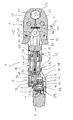
- the illustrated pressing apparatus 1 has an elongated drive unit 2, at one end of which a pressing tool 3 is coupled, which is suitable for the compression of press fittings, which serve to connect pipe ends.
- the drive unit 2 has, at the end opposite the pressing tool 3, a drive motor 4 whose output shaft 5 is coupled to a pump shaft 6 of a hydraulic pump designated as a whole by 7.
- the pump shaft 6 is guided in the hydraulic pump 7 in two bearings 8, 9 and has between the two bearings an eccentric 10 which acts via a needle bearing 11 on a radially displaceably guided pump piston 12.
- the pump piston 12 is moved radially back and forth.
- the housing of the hydraulic pump 7 is surrounded on the outside by an elastomeric hose 13 which encloses a hydraulic reservoir 14 between them and the outside of the hydraulic pump 7 in a liquid-tight manner.
- the ends of the tube 13 engage in grooves 15, 16 and are held there from the outside by pushed-over fixing rings 17, 18 in position.
- the hydraulic pump 7 is flanged in the axial direction on the side facing away from the electric motor 4 to a hydraulic motor in the form of a piston-cylinder unit 19.
- the piston-cylinder unit 19 has a hydraulic cylinder 20 which is closed on the hydraulic pump side with an end plate 21.
- a hydraulic piston 22 is guided displaceably. He divides the interior of the hydraulic cylinder 20 in an end plate-side pressure chamber 23 and a rear space 24 a.
- the hydraulic piston 22 is seated on a piston rod 25 which extends on the side facing away from the end plate 21 in the direction of the pressing tool 3.
- a hat-shaped sealing element 26 is inserted, which rests on the inside of the piston rod 25 and thus seals the rear space 24.
- the sealing element 26 also serves to support a piston spring 25 surrounding the coil spring 27, which is supported at the other end on the side remote from the pressure chamber 23 of the hydraulic piston 22.
- the coil spring 27 is formed as a compression spring and consequently endeavors to move the hydraulic piston 22 in the direction of the end plate 21.
- the hydraulic piston 22 remote from the end of the Kolbentsange 25 is rigidly connected outside of the rear space 24 with a spreader 28.
- the spreader 28 has a bearing body 29, are mounted on the two spreader rollers 30, 31 transversely to the axis of the pressing device 1 side by side and freely rotatable in mutual contact.
- Attached to the rear space-side end of the hydraulic cylinder 20 is a holder 32, the two Clutch plates 33, 34 forms, which extend in the axial direction of the pressing device 1.
- the coupling tabs 33, 34 have such a distance from each other that the spreader 28 can move between them.
- end coupling bores are provided which extend transversely to the longitudinal axis of the pressing device 1 and are aligned.
- two mutually parallel pressing tool tabs of which in FIG. 1 only the rear pressing tool tab 35 can be seen.
- Both press tool tabs 35 also have coupling holes that are aligned with each other and have the same diameter as the coupling holes in the coupling tabs 33, 34.
- connection between the coupling tabs 33, 34 and thus the drive unit 2 is made by a coupling pin 36 through passed through all four coupling holes and locked for the purpose of its positional fixation. In this way, the pressing tool 3 is pivotally connected to the drive unit 2.
- the press tool flaps 35 are of identical construction and are arranged congruently and at a distance. They are connected to each other via two hinge pins 37, 38. In the intermediate space between the press tool tabs 35, mirror-shaped press jaw levers 39, 40 are mounted pivotably on the hinge pins 37, 38.
- the pressing jaw levers 39, 40 form semicircular pressing jaws 41, 42 at their outer ends, which in the illustrated, closed state of the pressing tool 3 enclose a pressing space 43.
- a compression spring 44 ensures that the pressing jaw lever 39, 40 take the illustrated closed final pressing position in the idle state.
- the pressing jaw levers 39, 40 form drive surfaces 45, 46, which interact with the cylindrical surfaces of the spreading rollers 30, 31 during the pressing process.
- the hydraulic pump 7, i. their limited by the pump piston 12 pressure chamber has not shown here hydraulic channels on the one hand connection to the hydraulic reservoir 14 and the other to the pressure chamber 23 in the piston-cylinder unit 19.
- a check valve in the hydraulic line to the hydraulic reservoir 14 ensures that the pump piston 12th Upon movement in one direction, hydraulic oil sucks from the hydraulic reservoir 14 and, when moved in the other direction, conveys the sucked-in hydraulic oil into the pressure chamber 23.
- the hydraulic piston 22 and thus also the piston rod 25 and the spreader 28 connected thereto are moved in the direction of the pressing tool 3.
- a pressure relief valve 47 is formed in the form of a needle valve.
- the hydraulic piston 22 has a pressure opening 23 open valve opening 48, which serves as a valve seat for a valve body 49 on the inside. This is loaded in the direction of the valve opening 48 by means of a pressure acting on the rear side of the valve body 49 compression spring 50.
- the compression spring 50 is designed so that it allows a lifting of the valve body 49 only at a certain cut-off pressure in the Druchraum 23.
- the valve body 49 defines a valve chamber 51, which has a connection to the rear space 24 via a hydraulic channel, not shown here. This in turn is connected via a hydraulic channel, also not shown, with the hydraulic reservoir 14. All above-described hydraulic channels form a total of a hydraulic system.
- an emergency valve 52 which is also designed as a needle valve. It has a connecting channel 53 direct connection to the pressure chamber 23.
- the connecting channel 53 narrows into a valve seat insert 54, which forms a valve seat on the inside, on which a valve needle 55 sealingly abuts.
- the valve needle 55 with a Compressed spring 56 loaded.
- This compression spring 56 is designed so that the valve needle 55 only lifts off from the valve seat insert 54 and thus the emergency valve 52 opens when the pressure in the pressure chamber 23 has reached a value which is at least equal to the cut-off, at which the pressure relief valve 47 at normal function opens, but can also lie about it.
- the valve chamber of the emergency valve 52 has a channel, not shown here, connection to the hydraulic reservoir 14, so that the hydraulic fluid in the pressure chamber 23 can flow into the hydraulic reservoir 14 when opening the emergency valve 50.
- a manual override device 57 is provided, with the aid of which it is possible to effect an opening of the emergency valve 52 by external action.
- the manual actuation device 57 has an actuation tappet 58, which is displaceably guided transversely to the axial extension of the valve needle 55 and ends near the tube 13 within the hydraulic reservoir 14.
- actuation tappet 58 is displaceably guided transversely to the axial extension of the valve needle 55 and ends near the tube 13 within the hydraulic reservoir 14.
- a transverse pin 60 passing through the actuating tappet 58 prevents rotation of the actuating tappet 58 and forms a stop for the starting position.
- valve needle 55 At the valve needle end of the actuating plunger 58 is penetrated by the valve needle 55 and forms there an inclined surface 61, against which a contact surface 62 of the valve needle 55 is applied. Due to this coupling, the valve needle 55 is lifted from the valve seat insert 54 against the action of the compression spring 56 when the actuating plunger 58 is moved by applying pressure to the hose 13 in the direction of the valve needle 55. Independently of this, the coupling between actuation tappet 58 and valve needle 55 allows the valve needle 55 to move freely in the opening direction, so that the actuation tappet 58 has no influence on the automatic opening behavior of the emergency valve 52.
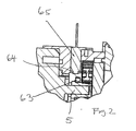
- the output shaft 5 carries a speed sensor 63, on the circumference of the same or unequal distances magnets 64 are distributed.
- the speed sensor 63 opposite is rotationally fixed Speed sensor 65 is arranged, which is capable of detecting the outgoing magnetic fields from the magnet 64 and emits corresponding signals to a control device not shown here. The signals are counted there, the speed of the drive motor 4 being determined from the number determined.
- the control device serves to control the course of the press via the drive motor, as is fundamentally understood from US Pat EP 0 860 220 is known.
- the control device additionally carries out a plausibility check at the end of a pressing operation in order to determine whether a pressing operation has been carried out successfully.
- a measured after opening the pressure relief valve 47 actual load speed of the drive motor 4 is in a predetermined target speed range.
- the upper limit of the target speed range determines the speed that must be fallen below to ensure that a predetermined pressing force has been reached.
- the lower limit for the allowable target load speed range is defined in order to detect overshoots of the permissible pressing force.
- the control device detects the idling speed before the beginning of a compression and predetermines the target load speed range as a function of the measured idling speed. If the determined idle speed is low, so will the load speed when opening the pressure relief valve will be lower, and in the reverse manner, the idle speed is high, so the load speed will be higher. Accordingly, depending on the before the pressing process measured idle speed of the target load speed range specified. This can be determined empirically, for example, and stored in the control device.
- the pressing device 1 is attached to the press fitting after previously compressed the two pressing jaw lever 39, 40 by hand to the spreader 28 adjacent ends against the action of the compression spring 44 and thus the pressing jaws 44 are removed from each other so that the end a mouth-like opening results.
- the pressing tool 3 can then be applied radially to the intended location of the press fitting, wherein the pressing jaws 41, 42 initially come to rest on the press fitting and accordingly the drive surfaces 45, 46 are approximated to each other.
- the electric motor 4 is set in motion via a switch not shown here.
- the idling speed is detected, and in dependence on it a target load speed range is defined, in which the speed of the electric motor 4 must be at the end of a successfully completed pressing operation.
- the hydraulic pump 7 sucks hydraulic fluid from the hydraulic reservoir 14 and conveys it into the pressure chamber 23.
- the lateral surfaces come the spreading rollers 30, 31 on the drive surfaces 45, 46 of the pressing jaw lever 39, 40 for conditioning and spread apart them gradually.
- the pressing jaws 41, 42 approach each other and thus ensure a compression of the press fitting radially inward. This continues until the pressing jaws 41, 42 come into mutual contact, so reach their final pressing position. This gradually increases the pressure in the Pressure chamber 23.
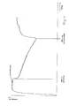
- the speed of the drive motor 4 decreases continuously, as in the FIG. 4 is recognizable.
- the pressure in the pressure chamber 23 still increases until the predetermined cut-off pressure is reached at which the pressure relief valve 47 opens by lifting the valve body 49 of the valve port 48.
- the control device detects the rotational speed of the electric motor 4 when opening the pressure relief valve. If the detected speed is within the predetermined target load speed range, the operator is notified via the signaling device that the pressing operation has been completed successfully.
- the operator turns off the electric motor 4, so that the hydraulic circulation is interrupted.
- an automatic shutdown of the electric motor 4 can take place.
- the rotational speed of the electric motor 4 increases steeply after the opening of the pressure relief valve 47. This speed increase can be used by the control device as a criterion to turn off the electric motor 4.
- the coil spring 27 then pushes the hydraulic piston 22 back towards the end plate 21. In this case, a pressure is generated in the pressure chamber 23, which is sufficient to keep the pressure relief valve 47 open during the entire return movement of the hydraulic piston 22 until the hydraulic piston 22 has reached the starting position shown in the figures again. Then the pressure relief valve 47 closes.
Abstract
Description
Die Erfindung betrifft eine handführbare Antriebseinrichtung für ein Pressgerät sowie ein Verfahren zum Steuern einer handführbaren Antriebseinrichtung für ein Pressgerät.The invention relates to a handleable drive device for a pressing device and a method for controlling a hand-held drive device for a pressing device.
Bekannte handführbare Antriebseinrichtungen für Pressgeräte weisen üblicherweise die folgenden Merkmale auf:
- die Antriebseinrichtung hat einen Antriebsmotor;
- der Antriebsmotor treibt eine Hydraulikpumpe an;
- die Hydraulikpumpe ist über ein Hydrauliksystem mit einem Hydraulikmotor verbunden;
- die Antriebseinrichtung weist vorzugsweise eine Kupplung für die Anbringung eines Presswerkzeugs zum Verpressen von Werkstücken auf;
- der Hydraulikmotor ist vorzugsweise mit einer Betätigungseinrichtung zur Betätigung des Presswerkzeugs gekoppelt;
- der Hydraulikmotor ist über das Hydrauliksystem mit einem Hydraulikreservoir verbunden;
- in dem Hydrauliksystem befindet sich zumindest ein Überdruckventil;
- das Überdruckventil ist derart ausgelegt, dass es bei Erreichen eines bestimmten Abschaltdruckes im Hydraulikmotor die Verbindung zu dem Hydraulikreservoir öffnet;
- der Hydraulikmotor weist vorzugsweise eine Rückstelleinrichtung auf, die den Hydraulikmotor nach Öffnen des Überdruckventils in seine Ausgangsstellung zurückbewegt und hierdurch Hydraulikflüssigkeit aus dem Hydraulikmotor in das Hydraulikreservoir befördert.
- the drive device has a drive motor;
- the drive motor drives a hydraulic pump;
- the hydraulic pump is connected to a hydraulic motor via a hydraulic system;
- the drive device preferably has a coupling for the attachment of a pressing tool for the pressing of workpieces;
- the hydraulic motor is preferably provided with an actuating device for Actuation of the pressing tool coupled;
- the hydraulic motor is connected via the hydraulic system to a hydraulic reservoir;
- in the hydraulic system is at least one pressure relief valve;
- the pressure relief valve is designed such that it opens the connection to the hydraulic reservoir upon reaching a certain cut-off pressure in the hydraulic motor;
- the hydraulic motor preferably has a return device, which moves the hydraulic motor back to its starting position after opening the pressure relief valve and thereby conveys hydraulic fluid from the hydraulic motor into the hydraulic reservoir.
Des weiteren betrifft die vorliegende Erfindung ein Pressgerät mit einer solchen Antriebseinrichtung.Furthermore, the present invention relates to a pressing device with such a drive device.
Zur Verbindung von Rohrleitungen mittels Pressfittings und für die Anbringung von Kabelschuhen an Elektroleitungen sind handführbare Pressgeräte bekannt, die aus einer Antriebseinrichtung und einem endseitig über eine Kupplung angebrachten, an den jeweiligen Verwendungszweck angepassten Presswerkzeug bestehen. Die Antriebseinrichtung ist bei der vorliegenden Gattung solcher Pressgeräte elektrohydraulisch ausgebildet. Dabei treibt ein netz- oder batteriegespeister, elektrischer Antriebsmotor einen Hydraulikpumpe an, die als Kolben- oder Zahnradpumpe ausgebildet sein kann. Die Hydraulikpumpe wirkt auf eine Betätigungseinrichtung in Form eines Hydraulikmotors. In der Regel ist ein solcher Hydraulikmotor als Kolben-Zylinder-Einheit mit einem in einem Hydraulikzylinder angeordneten Hydraulikkolben ausgebildet, dessen Kolbenstange auf das Presswerkzeug einwirkt. Bei Bewegung der Kolbenstange werden eine oder mehrere Pressbacken in dem Presswerkzeug in Pressrichtung bewegt. Bei dieser Art Antrieb wird also die Drehbewegung eines Antriebsmotors hydraulisch in eine Linearbewegung der Kolbenstange umgesetzt, um für eine Pressbewegung des Presswerkzeuges zu sorgen. Beispiele solcher Pressgeräte finden sich in
Zu der Hydraulikpumpe gehört ein Hydraulikreservoir, aus dem die Hydraulikpumpe Hydraulikflüssigkeit über ihre Saugseite ansaugt und über ihre Druckseite in den Druckraum der Kolben-Zylinder-Einheit fördert. Zu dem Hydrauliksystem gehört auch eine Verbindung zwischen der Druckseite des Hydraulikmotors und dem Hydraulikreservoir.To the hydraulic pump includes a hydraulic reservoir, from which the hydraulic pump sucks hydraulic fluid through its suction side and promotes via its pressure side in the pressure chamber of the piston-cylinder unit. The hydraulic system also includes a connection between the pressure side of the hydraulic motor and the hydraulic reservoir.
In dem Hydrauliksystem zwischen Hydraulikmotor und Hydraulikreservoir ist ein Überdruckventil angeordnet, das beim Pressvorgang zunächst geschlossen ist und erst bei Erreichen eines bestimmten Höchstdruckes, auch Abschaltdruck genannt, zum Hydraulikreservoir hin öffnet. Der Abschaltdruck ist so hoch ausgelegt, dass bei einem normalen Pressvorgang ein Öffnen erst stattfindet, wenn der Pressvorgang abgeschlossen ist, also das Presswerkzeug seine Endpressstellung erreicht hat.In the hydraulic system between hydraulic motor and hydraulic reservoir, a pressure relief valve is arranged, which is initially closed during the pressing process and only when reaching a certain maximum pressure, also called cut-off pressure, opens to the hydraulic reservoir. The cut-off pressure is designed so high that in a normal pressing operation opening only takes place when the pressing process is completed, so that the pressing tool has reached its final pressing position.
Mit dem Öffnen des Überdruckventils und ggf. dem Abschalten des Antriebsmotors und damit der Hydraulikpumpe wird der Hydraulikkolben mit einer auf ihn oder die Kolbenstange einwirkenden Rückstellfeder in seine Ausgangsstellung zurückbewegt. Hierdurch wird die in dem Druckraum befindliche Hydraulikflüssigkeit in das Hydraulikreservoir zurückgedrückt.With the opening of the pressure relief valve and possibly the switching off of the drive motor and thus of the hydraulic pump, the hydraulic piston is moved back to its starting position with a return spring acting on it or the piston rod. As a result, the hydraulic fluid in the pressure chamber is pushed back into the hydraulic reservoir.
Aus der
Ferner offenbart die
Die bekannten Überwachungssysteme haben sich in der Praxis durchaus bewährt. Die Bestrebungen gehen jedoch dahin, die Zuverlässigkeit zu erhöhen.The known monitoring systems have proven themselves in practice quite well. However, efforts are being made to increase reliability.
Aufgabe der Erfindung ist es eine handführbare Antriebseinrichtung für Pressgeräte zu schaffen, bei der die Zuverlässigkeit verbessert ist. Ferner ist es Aufgabe der Erfindung ein entsprechendes Verfahren zum Steuern einer handführbaren Antriebseinrichtung für Pressgeräte zu schaffen.The object of the invention is to provide a hand-held drive device for pressing devices, in which the reliability is improved. It is another object of the invention to provide a corresponding method for controlling a hand-held drive device for pressing devices.
Die Lösung der Aufgabe erfolgt erfindungsgemäß durch eine handführbare Antriebseinrichtung gemäß Anspruch 1 bzw. ein Verfahren zum Steuern einer handführbaren Antriebseinrichtung gemäß Anspruch 12.The object is achieved according to the invention by a handleable drive device according to
Erfindungsgemäß weist die handführbare Antriebseinrichtung für Pressgeräte einen Istwertaufnehmer zur Erfassung einer physikalischen Größe auf, welche mit dem Verpressungswiderstand korreliert und dem Antriebsmotor zugeordnet ist. Der Istwertaufnehmer ist einer Auswerteeinrichtung angeschlossen, in der ferner wenigstens ein Sollwertbereich gespeichert ist. Innerhalb des wenigstens einen gespeicherten Sollwertbereichs soll der Istwert der physikalischen Größe beim Erreichen des Abschaltdrucks liegen. Die Auswerteeinrichtung weist ferner eine Vergleichseinrichtung auf, die den erfassten Istwert mit dem Sollwertbereich vergleicht. Über eine Signaleinrichtung erfolgt eine Anzeige, ob der Istwertbereich in dem vorgegebenen Sollwertbereich liegt oder nicht.According to the invention, the hand-operable drive device for pressing devices has an actual value sensor for detecting a physical quantity, which correlates with the compression resistance and is assigned to the drive motor. The Istwertaufnehmer is connected to an evaluation, in which at least one setpoint range is stored. Within the at least one stored setpoint range, the actual value of the physical variable should lie when the cutoff pressure is reached. The evaluation device also has a comparison device which compares the detected actual value with the setpoint range. By means of a signal device, an indication is given as to whether the actual value range lies within the specified desired value range or not.
Eine bevorzugte Ausführungsform der Erfindung ist durch eines oder mehrere der folgenden Merkmale gekennzeichnet:
- es ist ein Istwertaufnehmer zur Erfassung einer pysikalischen Größe, welche mit dem Verpressungwiderstand korreliert und dem Antriebsmotor zugeordnet ist, vorgesehen;
- der Istwertaufnehmer ist an eine Auswerteeinrichtung angeschlossen;
- in der Auswerteeinrichtung ist wenigstens ein Sollwertbereich gespeichert, in dem der Istwert der pysikalischen Größe beim Erreichen des Abschaltdruckes liegen soll;
- die Auswerteeinrichtung weist eine Vergleichseinrichtung auf, die eine Überprüfung dahingehend vornimmt, ob der vom Istwertaufnehmer erfasste Istwert in dem vorgegebenen Sollwertbereich liegt;
- zu der Auswerteeinrichtung gehört eine Signaleinrichtung, welche anzeigt, ob der Istwert in dem vorgegebenen Sollwertbereich liegt;
- it is a Istwertaufnehmer for detecting a physical quantity, which correlates with the Verpressungwiderstand and the drive motor is assigned, provided;
- the Istwertaufnehmer is connected to an evaluation device;
- in the evaluation device, at least one setpoint range is stored, in which the actual value of the physical variable should lie when the cutoff pressure is reached;
- the evaluation device has a comparison device which carries out a check as to whether the actual value detected by the actual value pickup is within the predetermined desired value range;
- to the evaluation device includes a signaling device which indicates whether the actual value is within the predetermined setpoint range;
Der Erfindung liegt damit die Überlegung zugrunde, am Ende des Pressvorgangs einen Plausibilitätsprüfung vorzunehmen. Der Pressvorgang wird im Rahmen einer ersten Kontrolle beendet, wenn das Überdruckventil öffnet und damit ein vorgegebener Druck, der zu dem Pressdruck korreliert, aufgebaut ist. Im Rahmen der Plausibilitätsprüfung wird zusätzlich überprüft, ob die erfassten Daten bestätigen, dass auch der Antriebsmotor sich in einem Betriebszustand befindet, der einem erfolgreichen Pressvorgang entspricht. Einer Bedienungsperson wird dann angezeigt, ob der Pressvorgang ordnungsgemäß abgelaufen ist oder nicht.The invention is therefore based on the consideration to make a plausibility check at the end of the pressing process. The pressing process is terminated in a first control, when the pressure relief valve opens and thus a predetermined pressure, which correlates to the pressing pressure, is constructed. As part of the plausibility check, it is also checked whether the recorded data confirms that the drive motor is also in an operating condition that corresponds to a successful pressing process. An operator is then informed whether or not the pressing operation has been completed properly.
Als pysikalische Größe kann beispielsweise der dem Antrieb zugeführte elektrische Strom verwendet werden. In bevorzugter Weise ist jedoch vorgesehen, dass der Istwertaufnehmer zur Erfassung der Drehzahl des Antriebsmotors ausgebildet ist und in der Auswerteeinrichtung wenigstens ein Soll-Lastdreh-zahlbereich gespeichert ist, in dem die Lastdrehzahl des Antriebsmotors bei Erreichen des Abschaltdruckes liegen soll. Mit anderen Worten wird als Kennwert die Drehzahl des Antriebsmotors zum Zeitpunkt des Öffnens des Überdruckventils überwacht.As a physical quantity, for example, the electric current supplied to the drive can be used. Preferably, however, it is provided that the Istwertaufnehmer is designed to detect the rotational speed of the drive motor and in the evaluation at least one target load speed range is stored, in which the load speed of the drive motor should be on reaching the cut-off. In other words, the speed of the drive motor at the time of opening the pressure relief valve is monitored as the characteristic value.
Die Drehzahl korreliert zu der Presskraft in direkter Weise, wobei eine hohe Drehzahl gleich bedeutend zu einer niedrigen Last, und eine niedrige Drehzahl indikativ für eine hohe Last ist. Somit lässt sich eine Soll-Lastdrehzahl definieren, die für das Erreichen einer vorgeschriebenen Presskraft unterschritten werden muss. Das Unterschreiten dieser vordefinierten Soll-Lastdrehzahl bedeutet, dass die erforderlichen Presskraft erreicht wurde.The rotational speed correlates directly with the pressing force, with a high speed equal to a low load and a low speed indicative of a high load. Thus, a target load speed can be defined, which must be undercut for reaching a prescribed pressing force. Falling below this predefined target load speed means that the required pressing force has been achieved.
Grundsätzlich kann es ausreichend sein, nur eine Soll- Lastdrehzahl zu definieren, die unterschritten werden muss, um hieraus auf einen positiven Verlauf des Pressvorgangs zu schließen, In diesem Fall bildet die Soll-Lastdrehzahl die obere Grenze eines nach unten offenen SollLastdrehzahlbereiches, der in der Auswerteeinrichtung gespeichert ist. Zusätzlich kann auch eine untere Grenze für den zulässigen Soll-Lastdrehzahlbereich definiert werden, um auf diese Weise Überschreitungen der zulässigen Presskraft zu erkennen. Wenn die Motordrehzahl nach dem Öffnen des Überdruckventils in dem vorgegebenen Soll-Lastdrehzahlbereich liegt, erhält die Bedienungsperson eine Rückmeldung, dass der Pressvorgang erfolgreich abgeschlossen wurde. Hierzu kann eine beispielsweise eine akustische und/oder optische Signaleinrichtung vorgesehen sein.In principle, it may be sufficient to define only one target load speed which must be undershot in order to conclude from this a positive course of the pressing operation. In this case, the setpoint load speed forms the upper limit of a downwardly open setpoint load speed range, which in the Evaluation device is stored. In addition, a lower limit for the permissible target load speed range can also be defined in order to detect overshoots of the permissible pressing force in this way. When the engine speed is within the predetermined target load speed range after opening the relief valve, the operator receives feedback that the pressing operation has been completed successfully. For this purpose, for example, be provided an acoustic and / or optical signaling device.
Abhängig vom Ladezustand der Akkus oder von der Span- nungslage des Stromnetzes sowie dem Motorzustand und der Umgebungstemperatur kann es zu stark unterschiedlichen Motordrehzahlen im Leerlauf und entsprechend auch unter Last kommen. Um diese Schwankungen auszugleichen, ist gemäß einer bevorzugten Ausführungsform der Erfindung vorgesehen, dass die Auswerteeinrichtung vor dem Beginn einer Verpressung die Leerlaufdrehzahl erfasst und in Abhängigkeit der gemessenen Leerlaufdrehzahl den Soll-Lastdrehzahlbereich vorgibt. Bei dieser Ausgestaltung wird also zunächst die Leerlaufdrehzahl gemessen. Dies ist die Drehzahl, mit der das Pressgerät unbelastet an einen Fitting heranfährt. Ist die Leerlaufdrehzahl gering, so wird auch die Lastdrehzahl beim Öffnen des Überdruckventils geringer sein, und ist in umgekehrter Weise die Leerlaufdrehzahl hoch, so wird auch die Lastdrehzahl höher liegen. Entsprechend wird in Abhängigkeit von der vor dem Pressvorgang gemessenen Leerlaufdrehzahl der Soll-Lastdrehzahlbereich vorgegeben. Dieser kann empirisch ermittelt sein.Depending on the state of charge of the batteries or the voltage level of the power supply as well as the engine condition and the ambient temperature, there may be very different idling engine speeds and correspondingly also come under load. In order to compensate for these fluctuations, it is provided according to a preferred embodiment of the invention that the evaluation device detects the idling speed before the beginning of a compression and predetermines the target load speed range as a function of the measured idling speed. In this embodiment, therefore, first the idle speed is measured. This is the speed with which the press unit moves without load to a fitting. If the idle speed is low, so will the load speed when opening the pressure relief valve will be lower, and in reverse, the idle speed is high, so the load speed will be higher. Accordingly, the target load speed range is predetermined as a function of the idle speed measured before the pressing process. This can be determined empirically.
In an sich bekannter Weise kann die Antriebseinrichtung gemäß der vorliegenden Erfindung eine Steuereinrichtung zur Beeinflussung des Antriebsmotors aufweisen, wobei die Auswerteeinrichtung an die Steuereinrichtung angeschlossen ist oder einen Teil von dieser bildet. Die Steuereinrichtung ist dabei in bevorzugter Weise so ausgebildet, dass sie den Antriebsmotor in Abhängigkeit von dem Ist- wert, welcher durch den Istwerteaufnehmer erfasst wird, steuert. Insbesondere kann die Steuereinrichtung den Antriebsmotor abschalten, wenn die Auswerteeinrichtung nach dem Öffnen des Überdruckventils einen Anstieg der durch den Istwerteaufnehmer erfassten Ist-Drehzahl feststellt.In a manner known per se, the drive device according to the present invention can have a control device for influencing the drive motor, wherein the evaluation device is connected to the control device or forms part of it. The control device is preferably designed so that it controls the drive motor in dependence on the actual value, which is detected by the Istwerteaufnehmer. In particular, the control device can switch off the drive motor if the evaluation device detects an increase in the actual rotational speed detected by the actual value pickup after opening the pressure relief valve.
In weiterer Ausgestaltung kann vorgesehen sein, dass der Istwertaufnehmer einen an der Ausgangswelle des Antriebsmotors oder an anderer Stelle des Antriebsstranges gehaltenen Signalgeber, über dessen Umfang insbesondere in gleichen oder ungleichen Abständen verteilt Kontaktgeber angeordnet sind, und einen gerätefesten Sensor, der die von den Kontaktgebern ausgehende Kontakte erfasst und entsprechende Signale an die Steuereinrichtung abgibt, aufweist, wobei die Steuereinrichtung aus den erfassten Signalen die Ist-Drehzahl ermittelt. Zweckmäßigerweise kann in diesem Fall der Drehzahlgeber an seinem Umfang einen Magnet oder mehrere Magneten als Kontaktgeber tragen und der Sensor die von den Magneten ausgehenden Magnetfelder erfasst und entsprechende Signale an die Steuereinrichtung abgeben. Optische Kontaktgeber sind auch möglich.In a further embodiment it can be provided that the Istwertaufnehmer a held on the output shaft of the drive motor or elsewhere in the drive train signal generator, distributed over the circumference, in particular at equal or unequal intervals contactors, and a device-fixed sensor, which emanates from the contactors Detects contacts and outputs corresponding signals to the control device has, wherein the control device determines the actual speed from the detected signals. Appropriately, in this case, the speed sensor carry at its periphery a magnet or more magnets as a contactor and the sensor detects the emanating from the magnet magnetic fields and emit appropriate signals to the controller. Optical contactors are also possible.
Bei dieser Ausgestaltung der Erfindung erhält der Drehzahlsensor von den an der Ausgangswelle des Antriebsmotors oder an anderer Stelle des Antriebsstranges angebrachten Magneten pro Motorraumdrehung jeweils einen oder mehrere Impulse, die gezählt werden. Aufgrund der bauartbedingten pulsierenden Belastung einer hydraulischen Kolbenpumpe kann eine Glättung des Drehzahlverlaufs notwendig sein. Diese geschieht rechnerisch und ist abhängig von dem Aufbau der Pumpe und der Getriebeübersetzung. Ein Vorteil dieses Verfahrens liegt darin, dass nur die Impulse gezählt und aus der Anzahl der Impulse die Drehzahl errechnet wird. Ein AD-Wandler wie bei Strom- oder Spannungsmessungen ist hier nicht erforderlich, was die Auswertung einfach macht.In this embodiment of the invention, the speed sensor receives one or more pulses from the magnets attached to the output shaft of the drive motor or elsewhere in the drive train per engine compartment rotation, which are counted. Due to the design-related pulsating load of a hydraulic piston pump, a smoothing of the speed curve may be necessary. This is done by calculation and is dependent on the structure of the pump and the gear ratio. An advantage of this method is that only counts the pulses and the speed is calculated from the number of pulses. An AD converter as in current or voltage measurements is not required here, which makes the evaluation easy.
Der Hydraulikmotor kann in an sich bekannter Weise als Kolben-Zylinder-Einheit mit einem Hydraulikzylinder und einem Hydraulikkolben ausgebildet sein. In diesem Fall hat es sich als vorteilhaft erwiesen, dass das Überdruckventil in dem Hydraulikkolben und/oder in einer Kolbenstange des Hydraulikkolbens angeordnet ist (vgl.
Ferner betrifft die Erfindung ein Verfahren zum Steuern einer handführbaren Antriebseinrichtung für ein Pressgerät, wobei das Verfahren vorzugsweise mit der vorstehend beschriebenen Antriebseinrichtung durchgeführt wird.Furthermore, the invention relates to a method for controlling a hand-held drive device for a pressing device, wherein the method is preferably carried out with the drive device described above.
Gemäß des erfindungsgemäßen Verfahrens wird zur Durchführung eines Pressvorgangs eine Hydraulikpumpe über ein Hydrauliksystem mit Hydraulikmotor von einem Antriebsmotor, bei dem es sich insbesondere um einen Elektromotor handelt, angetrieben. Bei Erreichen eines bestimmten Abschaltdrucks im Hydraulikmotor wird ein Überdruckventil geöffnet, so dass das Hydraulikmedium insbesondere in ein Hydraulikreservoir zurückgeführt wird.According to the method according to the invention, a hydraulic pump via a hydraulic system with to carry out a pressing operation Hydraulic motor of a drive motor, which is in particular an electric motor driven. Upon reaching a certain cut-off pressure in the hydraulic motor, a pressure relief valve is opened, so that the hydraulic medium is in particular returned to a hydraulic reservoir.
Ferner wird mit Hilfe eines Istwertaufnehmers erfindungsgemäß eine physikalische Größe erfasst, welche mit dem Verpressungswiderstand korreliert und dem Antriebsmotor zugeordnet ist. Die erste physikalische Größe wird mit wenigstens einem vorgegebenen Sollwertbereich verglichen. Hierbei definiert der Sollwertbereich den Istwert der physikalischen Größe, in dem dieser bei Erreichen des Abschaltdrucks liegen soll. Ferner wird angezeigt, ob der Istwert in dem vorgegebenen Sollwertbereich liegt.Furthermore, with the aid of an actual value sensor, a physical quantity is detected according to the invention, which is correlated with the compression resistance and assigned to the drive motor. The first physical quantity is compared with at least one predetermined setpoint range. In this case, the setpoint range defines the actual value of the physical variable in which it should lie when the cutoff pressure is reached. It also indicates whether the actual value lies within the specified setpoint range.
Vorzugsweise erfasst der Istwertaufnehmer eine Ist-Drehzahl des Antriebsmotors, wobei der Antriebsmotor vorzugsweise mittels einer Steuereinrichtung in Abhängigkeit des erfassten Istwerts insbesondere der erfassten Ist-Drehzahl beim Erreichen des Abschaltdrucks gesteuert wird.Preferably, the Istwertaufnehmer detects an actual speed of the drive motor, wherein the drive motor is preferably controlled by means of a control device in response to the detected actual value in particular the detected actual speed when reaching the cut-off.
In bevorzugter Ausführungsform wird in einer Auswerteeinrichtung die nach dem Öffnen des Überdruckventils erfasste Ist-Drehzahl mit einem gespeicherten Soll-Drehzahlbereich verglichen. Durch einen derartigen Vergleich kann im Rahmen der Plausibilitätsprüfung sichergestellt werden, dass eine ordnungsgemäße Verpressung durchgeführt wurde, wenn die erfasste Ist-Drehzahl sich in dem Soll-Drehzahlbereich befindet. Vorzugsweise kann mittels einer Signaleinrichtung angezeigt werden, ob die Ist-Drehzahl innerhalb des gespeicherten Soll-Drehzahlbereichs liegt und somit eine ordnungsgemäße Verpressung durchgeführt wurde.In a preferred embodiment, the detected after opening the pressure relief valve actual speed is compared with a stored target speed range in an evaluation. By means of such a comparison, it can be ensured in the context of the plausibility check that a correct compression has been carried out when the detected actual rotational speed is within the desired rotational speed range. Preferably, it can be displayed by means of a signaling device, whether the actual speed is within the stored target speed range and thus a proper compression was performed.
Wie vorstehend anhand der Antriebseinrichtung in bevorzugter Ausführungsform erläutert, wird vorzugsweise vor Beginn der Verpressung die Leerlaufdrehzahl des Antriebsmotors erfasst und sodann in Abhängigkeit der gemessenen Leerlaufdrehzahl der Soll-Drehzahlbereich vorgegeben.As explained above with reference to the drive device in a preferred embodiment, is preferably before the beginning of the compression Idle speed of the drive motor detected and then specified depending on the measured idle speed of the target speed range.
In der Zeichnung ist die Erfindung anhand eines Ausführungsbeispiels näher veranschaulicht. Es zeigen:
Figur 1- einen Längsschnitt durch das erfindungsgemäße Pressgerät zum Verpressen von Pressfittings,
Figur 2- den Ausschnitt
X aus Figur 1 in vergrößerter Ansicht, - Figur 3
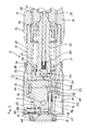
- einen vergrößerten Ausschnitt des Mittelbereichs des Pressgerätes aus
Figur 1 in einer Ebene, die um die Achse des Pressgerätes um 90° versetzt ist, und Figur 4- ein Diagramm, das einen möglichen Drehzahlverlauf während eines Pressvorgangs darstellt.
- FIG. 1
- a longitudinal section through the pressing device according to the invention for pressing press fittings,
- FIG. 2
- the cutout X out
FIG. 1 in an enlarged view, - FIG. 3
- an enlarged section of the central region of the pressing device
FIG. 1 in a plane which is offset by 90 ° about the axis of the pressing device, and - FIG. 4
- a diagram showing a possible speed curve during a pressing process.
Das dargestellte Pressgerät 1 weist eine langgestreckte Antriebseinheit 2 auf, an deren einem Ende ein Presswerkzeug 3 angekuppelt ist, das für die Verpressung von Pressfittings geeignet ist, die der Verbindung von Rohrenden dienen.The illustrated
Die Antriebseinheit 2 hat an dem dem Presswerkzeug 3 gegenüberliegenden Ende einen Antriebsmotor 4, dessen Ausgangswelle 5 mit einer Pumpenwelle 6 einer insgesamt mit 7 bezeichneten Hydraulikpumpe gekoppelt ist. Die Pumpenwelle 6 ist in der Hydraulikpumpe 7 in zwei Lagern 8, 9 geführt und hat zwischen den beiden Lagern einen Exenter 10, der über ein Nadellager 11 auf einen radial verschieblich geführten Pumpenkolben 12 wirkt. Bei angetriebener Pumpenwelle 6 wird der Pumpenkolben 12 radial hin- und herbewegt.The
Das Gehäuse der Hydraulikpumpe 7 ist außenseitig von einem elastomeren Schlauch 13 umgeben, der zwischen sich und der Außenseite der Hydraulikpumpe 7 ein Hydraulikreservoir 14 flüssigkeitsdicht einschließt. Hierzu fassen die Enden des Schlauchs 13 in Nuten 15, 16 ein und werden dort von außen durch übergeschobene Fixierringe 17, 18 in Position gehalten.The housing of the
Die Hydraulikpumpe 7 ist in axialer Richtung auf der dem Elektromotor 4 abgewandten Seite an einen Hydraulikmotor in Form einer Kolben-Zylinder-Einheit 19 angeflanscht. Die Kolben-Zylinder-Einheit 19 weist einen Hydraulikzylinder 20 auf, der hydraulikpumpenseitig mit einer Endplatte 21 verschlossen ist. In dem Hydraulikzylinder 20 ist ein Hydraulikkolben 22 verschieblich geführt. Er teilt den Innenraum des Hydraulikzylinders 20 in einen endplattenseitigen Druckraum 23 und einen Rückraum 24 ein.The
Der Hydraulikkolben 22 sitzt auf einer Kolbenstange 25, die sich auf der der Endplatte 21 abgewandten Seite in Richtung auf das Presswerkzeug 3 erstreckt. Am dortigen Ende des Hydraulikkolbens 22 ist ein hutförmiges Dichtungselement 26 eingesetzt, das innenseitig an der Kolbenstange 25 anliegt und so den Rückraum 24 abdichtet. Das Dichtungselement 26 dient zudem der Abstützung einer die Kolbenstange 25 umgebenden Schraubenfeder 27, die sich anderenends an der dem Druckraum 23 abgewandten Seite des Hydraulikkolbens 22 abstützt. Die Schraubenfeder 27 ist als Druckfeder ausgebildet und folglich bestrebt, den Hydraulikkolben 22 in Richtung auf die Endplatte 21 zu bewegen.The
Das dem Hydraulikkolben 22 abgewandte Ende der Kolbentsange 25 ist außerhalb des Rückraums 24 mit einer Spreizeinrichtung 28 starr verbunden. Die Spreizeinrichtung 28 weist einen Lagerkörper 29 auf, an dem zwei Spreizrollen 30, 31 quer zur Achse des Pressgerätes 1 nebeneinander und in gegenseitigem Kontakt frei drehbar gelagert sind. An dem rückraumseitigen Ende des Hydraulikzylinders 20 angebracht ist eine Halterung 32, die zwei Kupplungslaschen 33, 34 ausbildet, welche sich in Achsrichtung des Pressgeräts 1 erstrecken. Die Kupplungslaschen 33, 34 haben einen solchen Abstand zueinander, dass sich die Spreizeinrichtung 28 zwischen ihnen bewegen kann. An den Enden der Kupplungslaschen 33, 34 sind endseitig Kupplungsbohrungen vorgesehen, die sich quer zur Längsachse des Pressgerätes 1 erstrecken und miteinander fluchten. In den Bereich dieser Kupplungsbohrungen und zwischen die Kupplungslaschen 33, 34 hinein fassen in an sich bekannter Weise (vgl. beispielsweise
Die Presswerkzeuglaschen 35 sind identisch ausgebildet sowie deckungsgleich und beabstandet angeordnet. Sie sind über zwei Gelenkbolzen 37, 38 miteinander verbunden. In dem Zwischenraum zwischen den Presswerkzeuglaschen 35 sind auf den Gelenkbolzen 37, 38 spiegelbildlich ausgebildete Pressbackenhebel 39, 40 schwenkbar gelagert. Die Pressbackenhebel 39, 40 bilden an ihren äußeren Enden halbkreisförmige Pressbacken 41, 42 aus, die in dem dargestellten, geschlossenen Zustand des Presswerkzeuges 3 einen Pressraum 43 einschließen. Eine Druckfeder 44 sorgt dafür, dass die Pressbackenhebel 39, 40 im Ruhezustand die dargestellte geschlossene Endpressstellung einnehmen. An den gegenüberliegenden Enden bilden die Pressbackenhebel 39, 40 Antriebsflächen 45, 46 aus, die beim Pressvorgang mit den Zylinderflächen der Spreizrollen 30, 31 zusammenwirken.The press tool flaps 35 are of identical construction and are arranged congruently and at a distance. They are connected to each other via two hinge pins 37, 38. In the intermediate space between the
Die Hydraulikpumpe 7, d.h. deren durch den Pumpenkolben 12 begrenzte Druckraum hat über hier nicht dargestellte Hydraulikkanäle einerseits Verbindung zu dem Hydraulikreservoir 14 und andererseits zu dem Druckraum 23 in der Kolben-Zylinder-Einheit 19. Ein Rückschlagventil in der Hydraulikleitung zu dem Hydraulikreservoir 14 sorgt dafür, dass der Pumpenkolben 12 bei Bewegung in einer Richtung Hydrauliköl aus dem Hydraulikreservoir 14 ansaugt und bei Bewegung in der anderen Richtung das angesaugte Hydrauliköl in den Druckraum 23 befördert. Hierdurch werden der Hydraulikkolben 22 und damit auch die Kolbenstange 25 und die damit verbundene Spreizeinrichtung 28 in Richtung auf das Presswerkzeug 3 bewegt.The
Im Bereich der Verbindung von Hydraulikkolben 22 und Kolbenstange 25 ist ein Überdruckventil 47 in Form eines Nadelventils ausgebildet. Hierzu weist der Hydraulikkolben 22 eine zum Druckraum 23 offene Ventilöffnung 48 auf, die innenseitig als Ventilsitz für einen Ventilkörper 49 dient. Dieser ist in Richtung auf die Ventilöffnung 48 mittels einer die Rückseite des Ventilkörpers 49 beaufschlagenden Druckfeder 50 belastet. Die Druckfeder 50 ist so ausgelegt, dass sie ein Abheben des Ventilkörpers 49 erst bei einem bestimmten Abschaltdruck im Druchraum 23 zulässt. Der Ventilkörper 49 begrenzt einen Ventilraum 51, der über einen hier nicht dargestellten Hydraulikkanal Verbindung zu dem Rückraum 24 hat. Dieser wiederum ist über einen ebenfalls nicht dargestellten Hydraulikkanal mit dem Hydraulikreservoir 14 verbunden. Sämtliche vorbeschriebenen Hydraulikkanäle bilden insgesamt ein Hydrauliksystem.In the region of the connection of
Wie nur aus
Im hinteren Bereich der Ventilnadel 55 ist eine Handbetätigungseinrichtung 57 vorgesehen, mit deren Hilfe es möglich ist, durch Einwirkung von außen eine Öffnung des Notfallventils 52 zu bewirken. Die Handbetätigungseinrichtung 57 hat hierzu einen Betätigungsstößel 58, der quer zur axialen Erstreckung der Ventilnadel 55 verschieblich geführt ist und innerhalb des Hydraulikreservoirs 14 nahe des Schlauchs 13 endet. Über eine Druckfeder 59 wird er in der gezeigten Ausgangsstellung gehalten. Ein den Betätigungsstößel 58 durchsetzender Querbolzen 60 verhindert eine Verdrehung des Betätigungsstößels 58 und bildet einen Anschlag für die Ausgangsstellung. Am ventilnadelseitigen Ende wird der Betätigungsstößel 58 von der Ventilnadel 55 durchsetzt und bildet dort eine Schrägfläche 61 aus, an der eine Anlagefläche 62 der Ventilnadel 55 anliegt. Aufgrund dieser Kopplung wird die Ventilnadel 55 von dem Ventilsitzeinsatz 54 gegen die Wirkung der Druckfeder 56 abgehoben, wenn der Betätigungsstößel 58 durch Druckausübung auf den Schlauch 13 in Richtung auf die Ventilnadel 55 verschoben wird. Unabhängig davon lässt die Kopplung zwischen Betätigungsstößel 58 und Ventilnadel 55 zu, dass die Ventilnadel 55 sich in Öffnungsrichtung frei bewegen kann, so das der Betätigungsstößel 58 keinen Einfluss auf das automatische Öffnungsverhalten des Notfallventils 52 hat.In the rear region of the
Wie in
In Abhängigkeit von dem Ladezustand der Akkus oder von der Spannungslage des Stromnetzes sowie dem Motorzustand und der Umgebungstemperatur kann es zu stark unterschiedlichen Motordrehzahlen im Leerlauf und entsprechend auch unter Last kommen. Um diese Schwankungen auszugleichen, ist vorgesehen, dass die Steuereinrichtung vor Beginn einer Verpressung die Leerlaufdrehzahl erfasst und in Abhängigkeit der gemessenen Leerlaufdrehzahl den SollLastdrehzahlbereich vorgibt. Ist die ermittelte Leerlaufdrehzahl gering, so wird auch die Lastdrehzahl beim Öffnen des Überdruckventils geringer sein, und ist in umgekehrter Weise die Leerlaufdrehzahl hoch, so wird auch die Lastdrehzahl höher liegen. Entsprechend wird in Abhängigkeit von der vor dem Pressvorgang gemessenen Leerlaufdrehzahl der Soll-Lastdrehzahlbereich vorgegeben. Dieser kann beispielsweise empirisch ermittelt, und in der Steuereinrichtung abgespeichert sein.Depending on the state of charge of the batteries or the voltage level of the power network and the engine condition and the ambient temperature can lead to very different engine speeds at idle and correspondingly under load. To compensate for these fluctuations, it is provided that the control device detects the idling speed before the beginning of a compression and predetermines the target load speed range as a function of the measured idling speed. If the determined idle speed is low, so will the load speed when opening the pressure relief valve will be lower, and in the reverse manner, the idle speed is high, so the load speed will be higher. Accordingly, depending on the before the pressing process measured idle speed of the target load speed range specified. This can be determined empirically, for example, and stored in the control device.
Für einen Pressvorgang wird das Pressgerät 1 an das Pressfitting angesetzt, nachdem zuvor die beiden Pressbackenhebel 39, 40 von Hand an den der Spreizeinrichtung 28 benachbarten Enden gegen die Wirkung der Druckfeder 44 zusammengedrückt und damit die Pressbacken 44 voneinander so entfernt werden, dass sich endseitig eine maulartige Öffnung ergibt. Das Presswerkzeug 3 kann dann radial an die vorgesehene Stelle des Pressfittings angesetzt werden, wobei die Pressbacken 41, 42 zunächst geöffnet zur Anlage am Pressfitting kommen und demgemäß die Antriebsflächen 45, 46 einander angenähert sind.For a pressing operation, the
Anschließend wird über einen hier nicht näher dargestellten Schalter der Elektromotor 4 in Gang gesetzt. In diesem Leerlaufbetrieb wird zunächst die Leerlaufdrehzahl erfasst, und in Abhängigkeit von ihr ein Soll-Lastdrehzahlbereich definiert, in welchem die Drehzahl des Elektromotors 4 am Ende eines erfolgreich abgeschlossenen Pressvorgangs liegen muss.Subsequently, the
Durch den Betrieb des Elektromotors 4 saugt die Hydraulikpumpe 7 Hydraulikflüssigkeit aus dem Hydraulikreservoir 14 und fördert sie in den Druckraum 23. Dies führt zu einer Translationsbewegung des Hydraulikkolbens 22 und über die Kolbenstange 25 der Spreizeinrichtung 28 in Richtung auf das Presswerkzeug 3. Dabei kommen die Mantelflächen der Spreizrollen 30, 31 an den Antriebsflächen 45, 46 der Pressbackenhebel 39, 40 zur Anlage und spreizen diese nach und nach auseinander. Dies wiederum hat zur Folge, dass sich die Pressbacken 41, 42 einander annähern und so für eine Verpressung des Pressfittings radial nach innen sorgen. Dies setzt sich solange fort, bis die Pressbacken 41, 42 in gegenseitige Anlage kommen, also ihre Endpressstellung erreichen. Dabei erhöht sich sukzessive der Druck im Druckraum 23. Gleichzeitig sinkt die Drehzahl des Antriebsmotors 4 kontinuierlich ab, wie in der
Auch nach Erreichen der Entpressstellung steigt der Druck im Druckraum 23 noch solange, bis der vorbestimmte Abschaltdruck erreicht ist, bei dem das Überdruckventil 47 durch Abheben des Ventilkörpers 49 von der Ventilöffnung 48 öffnet. Die zunächst auf den Querschnittventilöffnung 48 begrenzte Druckwirkung erfasst nun schlagartig die gesamte Fläche des wesentlich größeren Ventilkörpers 49, Die Hydraulikflüssigkeit kann jetzt in den Rückraum 24 und von dort in das Hydraulikreservoir 14 fließen.
Die Steuereinrichtung erfasst die Drehzahl des Elektromotors 4 beim Öffnen des Überdruckventils. Wenn die erfasste Drehzahl innerhalb des vorgegebenen SollLastdrehzahlbereiches liegt, wird der Bedienungsperson über die Signaleinrichtung angezeigt, dass der Pressvorgang erfolgreich abgeschlossen wurde.Even after reaching the Entpressstellung the pressure in the
The control device detects the rotational speed of the
Danach schaltet die Bedienungsperson den Elektromotor 4 ab, so dass der Hydraulikumlauf unterbrochen wird. Alternativ kann auch eine automatische Abschaltung des Elektromotors 4 erfolgen. Wie in der
Claims (17)
einem Antriebsmotor (4), der eine über ein Hydrauliksystem mit einem Hydraulikmotor (19) verbundene Hydraulikpumpe (7) aufweist,
wobei der Hydraulikmotor(19) über das Hydrauliksystem, in dem sich zumindest ein Überdrückventil (47) befindet, mit einem Hydraulikreservoir (14) verbunden ist,
wobei das Überdruckventil (47) derart ausgelegt ist, dass es bei Erreichen eines bestimmten Abschaltdruckes im Hydraulikmotor (19) die Verbindung zu dem Hydraulikreservoir (14) öffnet,
einem Istwertaufnehmer zur Erfassung einer physikalischen Größe, welche mit dem Verpressungswiderstand korreliert und dem Antriebsmotor (4) zugeordnet ist,
eine Auswerteeinrichtung, an die der Istwertaufnehmer angeschlossen ist und in der wenigstens ein Sollwertbereich gespeichert ist, in dem der Istwert der physikalischen Größe beim Erreichen des Abschaltdrucks liegen soll,
wobei die Auswerteeinrichtung eine Vergleichseinrichtung aufweist, die eine Überprüfung dahingehend vornimmt, ob der vom Istwertaufnehmer erfasste Istwert in dem vorgegebenen Sollwertbereich liegt und
eine Signaleinrichtung, die anzeigt, ob der Istwert in dem vorgegebenen Sollwertbereich liegt.Handleable drive device for a pressing device (1), with
a drive motor (4) having a hydraulic pump (7) connected via a hydraulic system to a hydraulic motor (19),
wherein the hydraulic motor (19) is connected to a hydraulic reservoir (14) via the hydraulic system in which at least one overpressure valve (47) is located,
wherein the pressure relief valve (47) is designed such that it opens the connection to the hydraulic reservoir (14) when a certain cut-off pressure in the hydraulic motor (19) is reached,
an actual value sensor for detecting a physical quantity which correlates with the compression resistance and is assigned to the drive motor (4),
an evaluation device to which the actual value sensor is connected and in which at least one setpoint range is stored, in which the actual value of the physical variable should lie when the cutoff pressure is reached,
wherein the evaluation device has a comparison device which carries out a check as to whether the actual value detected by the actual value pickup lies in the predetermined desired value range and
a signaling device which indicates whether the actual value is within the predetermined setpoint range.
zur Durchführung eines Pressvorgangs eine Hydraulikpumpe (7) über ein Hydrauliksystem mit Hydraulikmotor (19) von einem Antriebsmotor (4) angetrieben wird,
bei Erreichen eines bestimmten Abschaltdruckes im Hydraulikmotor (19) ein Überdruckventil (47) geöffnet wird,
von einem Istwertaufnehmer eine physikalische Größe erfasst wird, welche mit dem Verpressungswiderstand korreliert und dem Antriebsmotor (4) zugeordnet ist,
verglichen wird, ob der Istwert der physikalischen Größe in wenigstens einem vorgegebenen Sollwertbereich liegt und
angezeigt wird, ob der Istwert in dem vorgegebenen Soll-Bereich liegt.Method for controlling a hand-operable drive device for a pressing device (1), in which
for carrying out a pressing operation, a hydraulic pump (7) is driven by a drive motor (4) via a hydraulic system with a hydraulic motor (19),
upon reaching a certain cut-off pressure in the hydraulic motor (19) a pressure relief valve (47) is opened,
a physical value is detected by an actual value sensor, which correlates with the compression resistance and is assigned to the drive motor (4),
is compared, whether the actual value of the physical quantity is in at least one predetermined setpoint range and
is displayed, whether the actual value is within the predetermined target range.
Applications Claiming Priority (1)
| Application Number | Priority Date | Filing Date | Title |
|---|---|---|---|
| DE202009003197U DE202009003197U1 (en) | 2009-03-10 | 2009-03-10 | Handleable drive device for a pressing device |
Publications (3)
| Publication Number | Publication Date |
|---|---|
| EP2228178A2 true EP2228178A2 (en) | 2010-09-15 |
| EP2228178A3 EP2228178A3 (en) | 2011-09-28 |
| EP2228178B1 EP2228178B1 (en) | 2012-08-22 |
Family
ID=42145927
Family Applications (1)
| Application Number | Title | Priority Date | Filing Date |
|---|---|---|---|
| EP20100155961 Active EP2228178B1 (en) | 2009-03-10 | 2010-03-09 | Handheld drive device for a press device and method for controlling a handheld drive device for a press device |
Country Status (2)
| Country | Link |
|---|---|
| EP (1) | EP2228178B1 (en) |
| DE (1) | DE202009003197U1 (en) |
Cited By (2)
| Publication number | Priority date | Publication date | Assignee | Title |
|---|---|---|---|---|
| EP2501523B1 (en) | 2009-11-17 | 2015-04-29 | Novopress GmbH Pressen und Presswerkzeuge & Co. KG | Manually guided press device |
| EP3643422A1 (en) * | 2018-10-25 | 2020-04-29 | Von Arx AG | Pressing device for work pieces |
Families Citing this family (1)
| Publication number | Priority date | Publication date | Assignee | Title |
|---|---|---|---|---|
| DE202010015365U1 (en) * | 2010-11-11 | 2012-02-15 | Novopress Gmbh Pressen Und Presswerkzeuge & Co. Kg | tester |
Citations (2)
| Publication number | Priority date | Publication date | Assignee | Title |
|---|---|---|---|---|
| EP1230998A2 (en) | 2001-02-12 | 2002-08-14 | Rothenberger Werkzeuge Aktiengesellschaft | Method of automatically controling electro-hydraulic handtools and assembly therefor |
| US20070033984A1 (en) | 2000-04-28 | 2007-02-15 | Hans-Jorg Goop | Pressing tool and pressing process for extruding press fittings |
Family Cites Families (6)
| Publication number | Priority date | Publication date | Assignee | Title |
|---|---|---|---|---|
| US5125324A (en) | 1988-02-10 | 1992-06-30 | Daia Industry Co. Ltd. | Portable hydraulically operated device incorporating automatic drain valve |
| DE29703052U1 (en) | 1997-02-21 | 1997-04-03 | Novopress Gmbh | Press device for connecting workpieces |
| ES2277907T3 (en) | 2000-05-25 | 2007-08-01 | Von Arx Ag | COMPRESSION TOOL FOR COMPRESSION OF COUPLING ELEMENTS. |
| US6745611B2 (en) * | 2002-02-19 | 2004-06-08 | Fci Americas Technology, Inc. | Battery powered hydraulic tool |
| DE20303877U1 (en) | 2003-03-10 | 2003-05-08 | Novopress Gmbh | Hand-guided hydraulic press cylinder forms part of hydraulic reservoir |
| DE202004000215U1 (en) | 2004-01-08 | 2004-04-01 | Novopress Gmbh Pressen Und Presswerkzeuge & Co Kg | Hand-held press tool appliance for connection of pipes etc. has regulating valve which remains closed when hydraulic pump fails and system pressure is below switch-off pressure |
-
2009
- 2009-03-10 DE DE202009003197U patent/DE202009003197U1/en not_active Expired - Lifetime
-
2010
- 2010-03-09 EP EP20100155961 patent/EP2228178B1/en active Active
Patent Citations (2)
| Publication number | Priority date | Publication date | Assignee | Title |
|---|---|---|---|---|
| US20070033984A1 (en) | 2000-04-28 | 2007-02-15 | Hans-Jorg Goop | Pressing tool and pressing process for extruding press fittings |
| EP1230998A2 (en) | 2001-02-12 | 2002-08-14 | Rothenberger Werkzeuge Aktiengesellschaft | Method of automatically controling electro-hydraulic handtools and assembly therefor |
Cited By (3)
| Publication number | Priority date | Publication date | Assignee | Title |
|---|---|---|---|---|
| EP2501523B1 (en) | 2009-11-17 | 2015-04-29 | Novopress GmbH Pressen und Presswerkzeuge & Co. KG | Manually guided press device |
| EP3643422A1 (en) * | 2018-10-25 | 2020-04-29 | Von Arx AG | Pressing device for work pieces |
| US11772349B2 (en) | 2018-10-25 | 2023-10-03 | Emerson Professional Tools Ag | Pressing tool for pressing workpieces |
Also Published As
| Publication number | Publication date |
|---|---|
| EP2228178B1 (en) | 2012-08-22 |
| EP2228178A3 (en) | 2011-09-28 |
| DE202009003197U1 (en) | 2010-05-06 |
Similar Documents
| Publication | Publication Date | Title |
|---|---|---|
| DE102008024018B4 (en) | Method for operating a motor-operated hand pressing device and hand pressing device | |
| EP0860220B1 (en) | Pressing device | |
| EP2228177B1 (en) | Handheld drive device for a press device and method for controlling a handheld drive device for a press device | |
| EP1858740B1 (en) | Method and device for controlling a motor vehicle drive train | |
| DE102017106449A1 (en) | Multi-stage joining device and joining method for it | |
| WO2015185444A1 (en) | Method for operating a tongs system for use on a rig and corresponding tongs system, computer program for implementing the method and rig comprising a tongs system | |
| DE102016117313A1 (en) | Method for operating a working device and working device | |
| EP2228178B1 (en) | Handheld drive device for a press device and method for controlling a handheld drive device for a press device | |
| EP2511023B1 (en) | Hydraulically operated setting device with a hydraulic aggregate and a joining method for connecting at least two components | |
| WO2008009547A1 (en) | Kupplungssteller zur automatischen betätigung einer reibungskupplung | |
| EP3221619A1 (en) | Method for operating an automatic transmission apparatus and corresponding automatic transmission apparatus | |
| EP3643422B1 (en) | Pressing device for work pieces | |
| EP3513911B1 (en) | Pressing machine | |
| DE202004000215U1 (en) | Hand-held press tool appliance for connection of pipes etc. has regulating valve which remains closed when hydraulic pump fails and system pressure is below switch-off pressure | |
| DE4413190B4 (en) | Pressure relief valve and method for setting an opening pressure at the pressure relief valve | |
| DE10016752A1 (en) | Press tool has presence sensor for press jaws that provides signal with which start of press process is initiated or interrupted if missing or faulty press jaws detected. | |
| EP2189247B1 (en) | Drive device for a press device and press device with such a drive device | |
| EP1388404A1 (en) | Hydraulic assembly for an injection moulding machine | |
| DE102016219220B4 (en) | Hydraulic drive | |
| DE4241971C1 (en) | Contact carrier sleeve compression procedure using hydraulic press - requires independent sensors for limiting force exerted on contact carrier sleeve and displacement of hydraulic press tool | |
| EP2286936B1 (en) | Pressing tool | |
| DE3109684C2 (en) | Adjusting device for generating linear movements of various sizes | |
| DE102005042593A1 (en) | Combined hydraulic operating and hand brake operating method for motor vehicle, involves activating interlocking device by movement of transmission unit whose position is determined by electrical resistance test | |
| DE202008002200U1 (en) | Hand-held pressing device |
Legal Events
| Date | Code | Title | Description |
|---|---|---|---|
| PUAI | Public reference made under article 153(3) epc to a published international application that has entered the european phase |
Free format text: ORIGINAL CODE: 0009012 |
|
| AK | Designated contracting states |
Kind code of ref document: A2 Designated state(s): AT BE BG CH CY CZ DE DK EE ES FI FR GB GR HR HU IE IS IT LI LT LU LV MC MK MT NL NO PL PT RO SE SI SK SM TR |
|
| AX | Request for extension of the european patent |
Extension state: AL BA ME RS |
|
| PUAL | Search report despatched |
Free format text: ORIGINAL CODE: 0009013 |
|
| AK | Designated contracting states |
Kind code of ref document: A3 Designated state(s): AT BE BG CH CY CZ DE DK EE ES FI FR GB GR HR HU IE IS IT LI LT LU LV MC MK MT NL NO PL PT RO SE SI SK SM TR |
|
| AX | Request for extension of the european patent |
Extension state: AL BA ME RS |
|
| RIC1 | Information provided on ipc code assigned before grant |
Ipc: B25B 27/10 20060101AFI20110825BHEP Ipc: H01R 43/042 20060101ALI20110825BHEP Ipc: B25F 5/00 20060101ALI20110825BHEP Ipc: B21D 39/04 20060101ALI20110825BHEP |
|
| 17P | Request for examination filed |
Effective date: 20111119 |
|
| GRAP | Despatch of communication of intention to grant a patent |
Free format text: ORIGINAL CODE: EPIDOSNIGR1 |
|
| RIC1 | Information provided on ipc code assigned before grant |
Ipc: B21D 39/04 20060101ALI20120127BHEP Ipc: B25B 27/10 20060101AFI20120127BHEP Ipc: H01R 43/042 20060101ALI20120127BHEP Ipc: B25F 5/00 20060101ALI20120127BHEP |
|
| GRAS | Grant fee paid |
Free format text: ORIGINAL CODE: EPIDOSNIGR3 |
|
| GRAA | (expected) grant |
Free format text: ORIGINAL CODE: 0009210 |
|
| AK | Designated contracting states |
Kind code of ref document: B1 Designated state(s): AT BE BG CH CY CZ DE DK EE ES FI FR GB GR HR HU IE IS IT LI LT LU LV MC MK MT NL NO PL PT RO SE SI SK SM TR |
|
| REG | Reference to a national code |
Ref country code: GB Ref legal event code: FG4D Free format text: NOT ENGLISH |
|
| REG | Reference to a national code |
Ref country code: CH Ref legal event code: EP |
|
| REG | Reference to a national code |
Ref country code: IE Ref legal event code: FG4D Free format text: LANGUAGE OF EP DOCUMENT: GERMAN |
|
| REG | Reference to a national code |
Ref country code: AT Ref legal event code: REF Ref document number: 571697 Country of ref document: AT Kind code of ref document: T Effective date: 20120915 |
|
| REG | Reference to a national code |
Ref country code: DE Ref legal event code: R096 Ref document number: 502010001121 Country of ref document: DE Effective date: 20121018 |
|
| REG | Reference to a national code |
Ref country code: CH Ref legal event code: NV Representative=s name: ISLER AND PEDRAZZINI AG, CH |
|
| REG | Reference to a national code |
Ref country code: NL Ref legal event code: VDEP Effective date: 20120822 |
|
| REG | Reference to a national code |
Ref country code: LT Ref legal event code: MG4D Effective date: 20120822 |
|
| PG25 | Lapsed in a contracting state [announced via postgrant information from national office to epo] |
Ref country code: FI Free format text: LAPSE BECAUSE OF FAILURE TO SUBMIT A TRANSLATION OF THE DESCRIPTION OR TO PAY THE FEE WITHIN THE PRESCRIBED TIME-LIMIT Effective date: 20120822 Ref country code: IS Free format text: LAPSE BECAUSE OF FAILURE TO SUBMIT A TRANSLATION OF THE DESCRIPTION OR TO PAY THE FEE WITHIN THE PRESCRIBED TIME-LIMIT Effective date: 20121222 Ref country code: LT Free format text: LAPSE BECAUSE OF FAILURE TO SUBMIT A TRANSLATION OF THE DESCRIPTION OR TO PAY THE FEE WITHIN THE PRESCRIBED TIME-LIMIT Effective date: 20120822 Ref country code: HR Free format text: LAPSE BECAUSE OF FAILURE TO SUBMIT A TRANSLATION OF THE DESCRIPTION OR TO PAY THE FEE WITHIN THE PRESCRIBED TIME-LIMIT Effective date: 20120822 Ref country code: NO Free format text: LAPSE BECAUSE OF FAILURE TO SUBMIT A TRANSLATION OF THE DESCRIPTION OR TO PAY THE FEE WITHIN THE PRESCRIBED TIME-LIMIT Effective date: 20121122 |
|
| PG25 | Lapsed in a contracting state [announced via postgrant information from national office to epo] |
Ref country code: PT Free format text: LAPSE BECAUSE OF FAILURE TO SUBMIT A TRANSLATION OF THE DESCRIPTION OR TO PAY THE FEE WITHIN THE PRESCRIBED TIME-LIMIT Effective date: 20121224 Ref country code: SE Free format text: LAPSE BECAUSE OF FAILURE TO SUBMIT A TRANSLATION OF THE DESCRIPTION OR TO PAY THE FEE WITHIN THE PRESCRIBED TIME-LIMIT Effective date: 20120822 Ref country code: SI Free format text: LAPSE BECAUSE OF FAILURE TO SUBMIT A TRANSLATION OF THE DESCRIPTION OR TO PAY THE FEE WITHIN THE PRESCRIBED TIME-LIMIT Effective date: 20120822 Ref country code: LV Free format text: LAPSE BECAUSE OF FAILURE TO SUBMIT A TRANSLATION OF THE DESCRIPTION OR TO PAY THE FEE WITHIN THE PRESCRIBED TIME-LIMIT Effective date: 20120822 Ref country code: GR Free format text: LAPSE BECAUSE OF FAILURE TO SUBMIT A TRANSLATION OF THE DESCRIPTION OR TO PAY THE FEE WITHIN THE PRESCRIBED TIME-LIMIT Effective date: 20121123 |
|
| PG25 | Lapsed in a contracting state [announced via postgrant information from national office to epo] |
Ref country code: NL Free format text: LAPSE BECAUSE OF FAILURE TO SUBMIT A TRANSLATION OF THE DESCRIPTION OR TO PAY THE FEE WITHIN THE PRESCRIBED TIME-LIMIT Effective date: 20120822 |
|
| PG25 | Lapsed in a contracting state [announced via postgrant information from national office to epo] |
Ref country code: EE Free format text: LAPSE BECAUSE OF FAILURE TO SUBMIT A TRANSLATION OF THE DESCRIPTION OR TO PAY THE FEE WITHIN THE PRESCRIBED TIME-LIMIT Effective date: 20120822 Ref country code: RO Free format text: LAPSE BECAUSE OF FAILURE TO SUBMIT A TRANSLATION OF THE DESCRIPTION OR TO PAY THE FEE WITHIN THE PRESCRIBED TIME-LIMIT Effective date: 20120822 Ref country code: DK Free format text: LAPSE BECAUSE OF FAILURE TO SUBMIT A TRANSLATION OF THE DESCRIPTION OR TO PAY THE FEE WITHIN THE PRESCRIBED TIME-LIMIT Effective date: 20120822 Ref country code: ES Free format text: LAPSE BECAUSE OF FAILURE TO SUBMIT A TRANSLATION OF THE DESCRIPTION OR TO PAY THE FEE WITHIN THE PRESCRIBED TIME-LIMIT Effective date: 20121203 |
|
| PG25 | Lapsed in a contracting state [announced via postgrant information from national office to epo] |
Ref country code: SK Free format text: LAPSE BECAUSE OF FAILURE TO SUBMIT A TRANSLATION OF THE DESCRIPTION OR TO PAY THE FEE WITHIN THE PRESCRIBED TIME-LIMIT Effective date: 20120822 Ref country code: PL Free format text: LAPSE BECAUSE OF FAILURE TO SUBMIT A TRANSLATION OF THE DESCRIPTION OR TO PAY THE FEE WITHIN THE PRESCRIBED TIME-LIMIT Effective date: 20120822 |
|
| PLBE | No opposition filed within time limit |
Free format text: ORIGINAL CODE: 0009261 |
|
| STAA | Information on the status of an ep patent application or granted ep patent |
Free format text: STATUS: NO OPPOSITION FILED WITHIN TIME LIMIT |
|
| 26N | No opposition filed |
Effective date: 20130523 |
|
| PG25 | Lapsed in a contracting state [announced via postgrant information from national office to epo] |
Ref country code: BG Free format text: LAPSE BECAUSE OF FAILURE TO SUBMIT A TRANSLATION OF THE DESCRIPTION OR TO PAY THE FEE WITHIN THE PRESCRIBED TIME-LIMIT Effective date: 20121122 |
|
| REG | Reference to a national code |
Ref country code: DE Ref legal event code: R097 Ref document number: 502010001121 Country of ref document: DE Effective date: 20130523 |
|
| BERE | Be: lapsed |
Owner name: NOVOPRESS G.M.B.H. PRESSEN UND PRESSWERKZEUGE & C Effective date: 20130331 |
|
| PG25 | Lapsed in a contracting state [announced via postgrant information from national office to epo] |
Ref country code: MC Free format text: LAPSE BECAUSE OF NON-PAYMENT OF DUE FEES Effective date: 20130331 |
|
| PG25 | Lapsed in a contracting state [announced via postgrant information from national office to epo] |
Ref country code: CY Free format text: LAPSE BECAUSE OF FAILURE TO SUBMIT A TRANSLATION OF THE DESCRIPTION OR TO PAY THE FEE WITHIN THE PRESCRIBED TIME-LIMIT Effective date: 20120822 |
|
| REG | Reference to a national code |
Ref country code: FR Ref legal event code: ST Effective date: 20131129 |
|
| REG | Reference to a national code |
Ref country code: IE Ref legal event code: MM4A |
|
| PG25 | Lapsed in a contracting state [announced via postgrant information from national office to epo] |
Ref country code: IE Free format text: LAPSE BECAUSE OF NON-PAYMENT OF DUE FEES Effective date: 20130309 Ref country code: BE Free format text: LAPSE BECAUSE OF NON-PAYMENT OF DUE FEES Effective date: 20130331 Ref country code: FR Free format text: LAPSE BECAUSE OF NON-PAYMENT OF DUE FEES Effective date: 20130402 |
|
| PG25 | Lapsed in a contracting state [announced via postgrant information from national office to epo] |
Ref country code: MT Free format text: LAPSE BECAUSE OF FAILURE TO SUBMIT A TRANSLATION OF THE DESCRIPTION OR TO PAY THE FEE WITHIN THE PRESCRIBED TIME-LIMIT Effective date: 20120822 |
|
| GBPC | Gb: european patent ceased through non-payment of renewal fee |
Effective date: 20140309 |
|
| PG25 | Lapsed in a contracting state [announced via postgrant information from national office to epo] |
Ref country code: GB Free format text: LAPSE BECAUSE OF NON-PAYMENT OF DUE FEES Effective date: 20140309 |
|
| PG25 | Lapsed in a contracting state [announced via postgrant information from national office to epo] |
Ref country code: SM Free format text: LAPSE BECAUSE OF FAILURE TO SUBMIT A TRANSLATION OF THE DESCRIPTION OR TO PAY THE FEE WITHIN THE PRESCRIBED TIME-LIMIT Effective date: 20120822 |
|
| PG25 | Lapsed in a contracting state [announced via postgrant information from national office to epo] |
Ref country code: TR Free format text: LAPSE BECAUSE OF FAILURE TO SUBMIT A TRANSLATION OF THE DESCRIPTION OR TO PAY THE FEE WITHIN THE PRESCRIBED TIME-LIMIT Effective date: 20120822 |
|
| PG25 | Lapsed in a contracting state [announced via postgrant information from national office to epo] |
Ref country code: HU Free format text: LAPSE BECAUSE OF FAILURE TO SUBMIT A TRANSLATION OF THE DESCRIPTION OR TO PAY THE FEE WITHIN THE PRESCRIBED TIME-LIMIT; INVALID AB INITIO Effective date: 20100309 Ref country code: MK Free format text: LAPSE BECAUSE OF FAILURE TO SUBMIT A TRANSLATION OF THE DESCRIPTION OR TO PAY THE FEE WITHIN THE PRESCRIBED TIME-LIMIT Effective date: 20120822 Ref country code: LU Free format text: LAPSE BECAUSE OF NON-PAYMENT OF DUE FEES Effective date: 20130309 |
|
| PGFP | Annual fee paid to national office [announced via postgrant information from national office to epo] |
Ref country code: AT Payment date: 20160318 Year of fee payment: 7 |
|
| REG | Reference to a national code |
Ref country code: AT Ref legal event code: MM01 Ref document number: 571697 Country of ref document: AT Kind code of ref document: T Effective date: 20170309 |
|
| PG25 | Lapsed in a contracting state [announced via postgrant information from national office to epo] |
Ref country code: AT Free format text: LAPSE BECAUSE OF NON-PAYMENT OF DUE FEES Effective date: 20170309 |
|
| PGFP | Annual fee paid to national office [announced via postgrant information from national office to epo] |
Ref country code: CZ Payment date: 20230301 Year of fee payment: 14 |
|
| P01 | Opt-out of the competence of the unified patent court (upc) registered |
Effective date: 20230530 |
|
| PGFP | Annual fee paid to national office [announced via postgrant information from national office to epo] |
Ref country code: IT Payment date: 20230331 Year of fee payment: 14 Ref country code: CH Payment date: 20230402 Year of fee payment: 14 |
|
| PGFP | Annual fee paid to national office [announced via postgrant information from national office to epo] |
Ref country code: DE Payment date: 20240315 Year of fee payment: 15 Ref country code: CZ Payment date: 20240226 Year of fee payment: 15 |