EP2227065B1 - Verbesserungen an drahtlosen Netzen mit kurzer Reichweite - Google Patents
Verbesserungen an drahtlosen Netzen mit kurzer Reichweite Download PDFInfo
- Publication number
- EP2227065B1 EP2227065B1 EP09154363.7A EP09154363A EP2227065B1 EP 2227065 B1 EP2227065 B1 EP 2227065B1 EP 09154363 A EP09154363 A EP 09154363A EP 2227065 B1 EP2227065 B1 EP 2227065B1
- Authority
- EP
- European Patent Office
- Prior art keywords
- sensor
- coordinator
- sleep pattern
- network
- parameter
- Prior art date
- Legal status (The legal status is an assumption and is not a legal conclusion. Google has not performed a legal analysis and makes no representation as to the accuracy of the status listed.)
- Expired - Fee Related
Links
Images


Classifications
-
- H—ELECTRICITY
- H04—ELECTRIC COMMUNICATION TECHNIQUE
- H04W—WIRELESS COMMUNICATION NETWORKS
- H04W84/00—Network topologies
- H04W84/18—Self-organising networks, e.g. ad-hoc networks or sensor networks
-
- H—ELECTRICITY
- H04—ELECTRIC COMMUNICATION TECHNIQUE
- H04W—WIRELESS COMMUNICATION NETWORKS
- H04W52/00—Power management, e.g. TPC [Transmission Power Control], power saving or power classes
- H04W52/02—Power saving arrangements
-
- H—ELECTRICITY
- H04—ELECTRIC COMMUNICATION TECHNIQUE
- H04W—WIRELESS COMMUNICATION NETWORKS
- H04W52/00—Power management, e.g. TPC [Transmission Power Control], power saving or power classes
- H04W52/02—Power saving arrangements
- H04W52/0209—Power saving arrangements in terminal devices
- H04W52/0212—Power saving arrangements in terminal devices managed by the network, e.g. network or access point is master and terminal is slave
- H04W52/0216—Power saving arrangements in terminal devices managed by the network, e.g. network or access point is master and terminal is slave using a pre-established activity schedule, e.g. traffic indication frame
-
- H—ELECTRICITY
- H04—ELECTRIC COMMUNICATION TECHNIQUE
- H04W—WIRELESS COMMUNICATION NETWORKS
- H04W52/00—Power management, e.g. TPC [Transmission Power Control], power saving or power classes
- H04W52/02—Power saving arrangements
- H04W52/0209—Power saving arrangements in terminal devices
- H04W52/0212—Power saving arrangements in terminal devices managed by the network, e.g. network or access point is master and terminal is slave
- H04W52/0219—Power saving arrangements in terminal devices managed by the network, e.g. network or access point is master and terminal is slave where the power saving management affects multiple terminals
-
- Y—GENERAL TAGGING OF NEW TECHNOLOGICAL DEVELOPMENTS; GENERAL TAGGING OF CROSS-SECTIONAL TECHNOLOGIES SPANNING OVER SEVERAL SECTIONS OF THE IPC; TECHNICAL SUBJECTS COVERED BY FORMER USPC CROSS-REFERENCE ART COLLECTIONS [XRACs] AND DIGESTS
- Y02—TECHNOLOGIES OR APPLICATIONS FOR MITIGATION OR ADAPTATION AGAINST CLIMATE CHANGE
- Y02D—CLIMATE CHANGE MITIGATION TECHNOLOGIES IN INFORMATION AND COMMUNICATION TECHNOLOGIES [ICT], I.E. INFORMATION AND COMMUNICATION TECHNOLOGIES AIMING AT THE REDUCTION OF THEIR OWN ENERGY USE
- Y02D30/00—Reducing energy consumption in communication networks
- Y02D30/70—Reducing energy consumption in communication networks in wireless communication networks
Definitions
- the present invention relates to wireless personal area networks and particularly, but not necessarily exclusively, to wireless sensor networks and to body area networks including wirelessly-communicating sensors disposed on or around a human or animal body.
- the so-called Body Area Network or BAN is an example of wireless personal area networks (WPANs), used to convey information over relatively short distances. Unlike wireless local area networks (WLANs), connections effected via WPANs involve little or no infrastructure. This feature allows small, power-efficient, inexpensive solutions to be implemented for a wide range of devices.
- MBAN medical BAN
- a BAN employing mainly sensors for feeding sensed data to a data sink (which may also be a network co-ordinator) is an example of a wireless sensor network (WSN); however, more active devices, such as actuators, may be also be included in a WSN acting as an MBAN.
- wireless networks may be designed to include sensors and other devices.
- sensors arranged to measure a parameter such as temperature at various different positions on a turbine blade or other industrial part for monitoring.
- more active devices can be included in such a wireless network and little or no infrastructure is required.
- Standard IEEE 802.15.4 defines the physical layer (PHY) and medium access control (MAC) sublayer specifications for low data-rate WPANs, although the coverage of an IEEE 802.15.4 network may extend beyond a personal operating space (POS) which typically defines the WPAN and is thus also suitable for somewhat larger-scale industrial deployment. Such slightly larger-scale networks are included within the terms WSN, WPAN and BAN for the purposes of this application.
- IEEE 802.15.4 has some similarities with a standard for an ad-hoc piconet, IEEE 802.15.3. Such piconets around a person or object typically cover at least 10m in all directions and envelop the person or object, whether stationary or in motion. They include higher data-rate WPANs.
- the documents IEEE Std 802.15.4-2006 and IEEE Std 802.15.3-2003 are hereby incorporated by reference in their entirety.
- WPANs of the type envisaged in IEEE 802.15.4 are suitable for applications such as industrial monitoring, but do not offer the kind of data reliability required for MBANs.
- Sensors can provide the required intelligence, and already are widely employed in medical equipment. This includes hospital recuperative care, home care, intensive care units and advanced surgical procedures. There are many different types of sensors employed for medical applications, including external sensors for pulse, temperature etc., sensors which come in contact with body fluids, sensors used in catheters (through incision), sensors for external applications, disposable skin patches with wireless sensors, and implantable sensors.
- a WPAN of sensors around a patient in a hospital or medical ward could provide multiple clinical benefits including patient mobility, monitoring flexibility, extension of monitoring into care areas that are currently unmonitored, reduced clinical errors and reduced overall monitoring costs.
- Body worn sensors may include various sensor types on single patient body. They require a capability to be applied or removed quickly from the patient's body.
- Such sensors may have bit rates of as low as 1-2 kbps per patient and on an aggregate basis they may require a 10 kbps bit rate. A range of as little as 1 metre may be adequate.
- medical WSN applications are mission critical applications in the clinical environment. Robust wireless links for bounded data loss and bounded latency, capacity for patient and sensor density, coexistence with other radios, battery life for days of continuous operations and small form factors for body worn devices, are among the requirements for medical WSNs or MBANs.
- the Sleep/wake up pattern (referred to as sleep pattern in the following) is periodic and determines the length of time for which a device is awake during each period of time.
- the device for example a sensor, sends the measurements or other data it has already gathered. If the sensor finishes sending the measurement before the end of the wake up time, it goes back to sleep and follows the sleep pattern already set for it. If the sensor did not finish data transmission before the end of wake up time, it can continue the transmission of the measurement and then go back to sleep according to the sleep pattern.
- the sampling rate of measurement at the sensor and the transmission rate of measurement (duty cycle). For example there may be a scenario under which the measurement itself is very slow (e.g. large information gathered in a measurement attempt) and requires many transmission attempts to send the information on a piece-by-piece basis.
- sensor sleep patterns can be determined according to residual energy of the node.
- US 2006/0092907 discloses a sensor network in which each sensor node determines its own priority number and transmits the priority number to the base station in order to implement a sleep pattern.
- WO2006/038163 takes battery level and redundant transmission into consideration when determining sleep patterns of sensor nodes in a sensor network.
- the measurements arrive faster with a more aggressive transmission of the (faster) wake-up pattern.
- the primary reason to change the sleep pattern is to have more up-to-date and fresher information as to the life parameters (i.e. faster measurements).
- the nature of the medical or other critical application would decide how fast the sleep pattern is. For example, for cardiac applications it depends on the live entity we deal with. For humans the pattern is slower than for animals (say in extreme cases quarter of a second for human and tenth of second for a mouse).
- a wireless sensor network of devices including a sensor and a coordinator:
- the network of invention embodiments allows a coordinator to transmit suitable sleep patterns, so that centralised control of or at least influence on sleep patterns is provided.
- the sensor in the network detects values of a parameter and transmits information relating to these values directly or indirectly via other devices to the coordinator. This value information is used to determine an indication of a suitable sensor sleep pattern, which is then transmitted by the coordinator indirectly or directly to the sensor concerned.
- the term "operable" used herein thus includes the idea of the means defined being arranged to carry out the function specified in use.
- the indication may be provided and transmitted with other information. For example separate information as to an emergency status (perhaps in the form of an emergency bit) may be provided.
- the described sensor may be the only duty-cycling device in the wireless sensor network. More commonly, the sensor may be one of a plurality on duty-cycling devices in the network, the coordinator being operable to transmit suitable sleep patterns for each of the duty-cycling devices.
- the devices can be sensors, actuators or any other type of battery powered device used in the network.
- the coordinator influences the operation of each duty-cycling device by providing an indication of a suitable sleep pattern.
- Such central coordination allows flexible and enhanced network operation.
- the suitable sleep pattern transmitted to at least one of the duty-cycling devices takes into account an external factor, that is a factor not related to that device.
- at least one duty-cycling device in the network may receive a suitable sleep pattern which has been determined taking into account values detected by the sensor described previously.
- the parameter values can indicate an emergency state and centralised control of the suitable sleep pattern allocation can allow lower duty-cycle sleep patterns to be sent to other devices in the network, thus ensuring that sufficient network resources are available for the sensor in the emergency state.
- the emergency state could be defined in other ways, depending on the functionality of the device concerned. For example an actuator may be in an emergency state if it is instructed to operate at a high level, this emergency state then being used in the centralised control of suitable sleep patterns to influence other devices in the network.
- different devices may have different priorities. For example, there may be a differentiation between critical medical device (high priority), medical devices (middle priority) and non-medical devices (low priority). Such priorities can be used to allocate network resources.
- the allocation of the priority to each duty-cycling device can determine to what extent, if at all, the coordinator takes external factors (for example those relating to other devices in the network) into account to determine its suitable sleep pattern.
- the coordinator takes external factors (for example those relating to other devices in the network) into account to determine its suitable sleep pattern.
- a sensor may be categorised as a critical medical device and thus there may be no external influences on the suitable sleep patterns sent to this sensor.
- Low priority duty-cycling devices may have their sleep pattern reduced to lower duty-cycling as a result of an external factor based one or more higher priority duty-cycling devices in the network having an increased requirement for network resource, such as an emergency state.
- an emergency state there may be one or more than one emergency state predefined for duty-cycling devices, each higher emergency state having a more severe effect on the suitable sleep pattern transmitted to one or more other duty-cycling device in the network.
- the suitable sleep pattern may be determined in any suitable way, such as by an algorithm, by a simple calculation, use of a look-up table or by human intervention.
- the coordinator includes determining means which are used to determine the suitable sleep pattern.
- the coordinator can receive the suitable sleep pattern from a central monitoring unit, which is in wired or wireless connection with the coordinator.
- the central monitoring unit can be part of the wireless sensor network or not, depending on the WSN deployment.
- a central monitoring unit (also sometimes referred to as a central monitoring and medical care unit, in medical applications) can be a station with monitoring equipment capable of receiving continuous or occasional streams of emergency data from multiple stations (for example for multiple patients).
- the central monitoring unit may include operatives (such as nurses or medical specialists) whose role is to monitor the data received. These operatives can take action in response to changes in conditions, for example, in individual patients or industrial parts.
- a suitable sleep pattern is determined in the coordinator or in the central monitoring unit, it is transmitted wirelessly to the sensor where it is received using the sensor reception means.
- the transmission may be direct, or indirect via other network nodes.
- the skilled reader will appreciate that the transmission of the information as to the parameter values from the sensor to the coordinator can also be either direct or indirect.
- the information as to the parameter values can be transmitted in any suitable fashion, possibly within a data frame.
- the information may in fact comprise the actual parameter values, or the parameter values may be processed in some way by a sensor processing means to produce the information.
- the indication of a suitable sensor sleep pattern transmitted from the coordinator can also be provided in any suitable manner.
- the indication is transmitted in a control field of a transmission frame, for example using a value set in the MAC header, such as in the frame control field to a predetermined value.
- the value can be one or more bits acting in combination to designate a suitable predefined sleep pattern.
- the value could be in the frame control field of any transmission frame.
- the value could be a device state description (maybe a full octet, including the indication and potentially other information such as a warning/emergency status) in a MAC frame.
- the MAC frame control could include a device state bit to indicate whether the device state description should be read and interpreted.
- transmission of the indication takes priority over other transmissions from the coordinator. For example, transmissions including the indication can be scheduled before transmissions not including the indication. Alternatively, the indication can be sent in all transmission frames sent from the coordinator permanently, or over a particular time period.
- the network devices use acknowledgement functionality to allow for an acknowledgement of the indication and/or value information.
- the acknowledgement can be linked to a re-send if there is a failure.
- the detected values may be taken into account (for example in the coordinator or central monitoring unit) to determine a suitable sleep pattern by comparison against one or more thresholds, by detection of a change in the parameter or by detection of a rate of change or in any other suitable way for the parameter being measured. In many situations, a simple comparison against the thresholds is appropriate.
- the suitable sleep pattern can be defined in real time. For example one or more different thresholds, different values or different changes and rates of change can be used to calculate a suitable sleep pattern in terms of percentage wake-up time, time between transmissions or any other suitable definition.
- predefined sleep patterns can be stored, preferably in the network, for example in the sensor and/or coordinator and/or central monitoring unit.
- a lower wake-up sleep pattern may indicate a lower duty cycle or longer time between transmissions and a higher wake-up sleep pattern can indicate a higher duty cycle or shorter time between transmissions.
- control means can simply implement the sleep pattern which has been determined as suitable taking the detected values into account and transmitted to the sensor.
- a sensor as described above further comprises a battery, wherein the control means are operable to control the sleep pattern taking into account both the indication and a current battery charge of the sensor.
- the actual sleep pattern may be selected based on a combination of these factors and potentially other factors.
- control means may allow or reject suitable sleep patterns according to a predefined limit of acceptable battery charge.
- the control means can be designed to override any rejected suitable sleep pattern with a lower wake-up sleep pattern.
- the lower wake-up pattern is the predefined sleep pattern with the maximum wake-up pattern allowed by the battery.
- control means allowing fewer sleep patterns below each limit than above it, then preferably the number of limits is equal to the number of thresholds.
- the sensor transmitter is additionally operable to transmit information relating to the current battery charge, preferably in a control field of a transmission frame, as for the indication.
- Transmission frames used by the wireless sensor network can comprise both a control field for the indication and a control field for the current battery charge, each in the form of one or more bits.
- the same control field can be used for the battery charge information and the indication, transmission frames transmitted from the sensor towards the coordinator including the battery charge information in this control field and transmission frames transmitted from the coordinator towards the sensor including the indication in this control field.
- the coordinator reception means may be operable to receive the battery charge information and the coordinator can further comprise response means operable to respond to a predefined value of charging information by taking action with respect to the battery. For example, the coordinator may set a battery change alarm, in form the central monitoring unit of the situation or take any other appropriate action.
- the invention embodiments provide a coordinator in a wireless sensor network of devices including a sensor and the coordinator, wherein the coordinator comprises reception means operable to receive value information from the sensor as to the detected values of a parameter; determining means operable to determine a suitable sleep pattern for the sensor by comparing the transmitted value information with thresholds for the parameter; wherein a plurality of predefined sleep patterns is provided, the choice of a suitable sleep pattern being determined according to the parameter value thresholds, each threshold defining a boundary between a lower wake-up and a higher wake-up sleep pattern; and transmission means operable to transmit an indication of the suitable sleep pattern.
- invention embodiments provide a sensor in a wireless sensor network of devices including the sensor and a coordinator, the sensor comprising:
- invention embodiments provide a central monitoring unit, which in use is in wired or wireless communication with a wireless sensor network of devices including a sensor and a coordinator:
- embodiments of the invention relate to a method in a wireless sensor network of devices including a sensor and a coordinator, the method comprising detecting values of a parameter in the sensor, transmitting value information as to the parameter values from the sensor towards the coordinator, transmitting an indication of a suitable sensor sleep pattern determined centrally by comparing the transmitted value information with thresholds for the parameter from the coordinator towards the sensor and controlling a sleep pattern of the sensor taking into account the indication; wherein a plurality of predefined sleep patterns is provided, the choice of a suitable sleep pattern being determined according to parameter value thresholds, each threshold defining a boundary between a lower wake-up and a higher wake-up sleep pattern.
- FIG 1 shows the general architecture of a IEEE 802.15.4 WPAN, labelled 100, in terms of the layered OSI model, in which the physical medium is accessed via a PHY layer containing the radio transceiver and its low-level control.
- the lower frequency band 101 provides a single 20kb/s channel centred on 868.3MHz, and/or ten channels each of 40kb/s centred on 915MHz.
- the higher frequency band 102 provides 16 channels each of 250kb/s and centred on a frequency of 2.44 GHz. Which of these bands is used will depend on local regulatory requirements.
- MAC Medium Access Control
- LLC Link Layer Control
- the MAC sublayer One task of the MAC sublayer is to control the network topology.
- Star and peer-to-peer are two known topologies in communications networks, and both are provided for in IEEE 802.15.4. In both cases, the topology distinguishes between two basic kinds of network node: devices and coordinators. As shown in Fig.3 , in the Star topology a number of devices 11 communicate directly with a central co-ordinator 10; whilst in the peer-to-peer configuration, communications by a device 11A with the communicator are made along one or more hops with intermediate devices 11B and 11C acting as relays.
- the coordinator acts as the access point to the upper layers; in the case of a WSN, it acts as the sink for the data collected by the sensors. Given that the communication range of each device may be very limited (a few metres), the peer-to-peer topology allows a greater area to be covered.
- the topology may be dynamic, changing as devices are added or leave the network.
- a star network might be appropriate to monitor readings from sensor on a single stationary item of machinery with moving parts.
- a peer-to-peer topology could be used to monitor objects on a conveyer belt.
- a star network would be appropriate in the case where a coordinator is provided at each patient site (such as a hospital bed), exchanging signals with devices on a single patient.
- Peer-to-peer would be a more appropriate topology where one coordinator was provided to serve a number of patients (the coordinator might be located at a fixed point in a hospital ward).
- the coordinator may be either mobile or fixed.
- Peer-to-peer networks may also be more suited to fast-changing environments where it is required to set up or change the network quickly, or to allow self-organiz and self-healing of the network. Self-healing may include, for example, establishing a new coordinator in the event that an existing coordinator has failed or left the network.
- Multiple star and/or peer-to-peer networks may be set up in the same location such as a hospital or factory, each with their own coordinator. In this case it will be necessary for the respective coordinators to collaborate in order to avoid mutual interference and to allow sharing or collation of data.
- IEEE 802.15.4 such networks are called clusters, and provision is made for establishing an overall coordinator for the clusters as well as for dividing and merging clusters.
- Nodes in a WPAN may be constituted by units of varying capabilities.
- the role of coordinator will require a relatively capable apparatus with some processing power and transceiver capable of handling transmissions from multiple sources simultaneously. This in turn will necessitate a sufficient provision of electrical power (in some cases, it may be mains powered).
- other devices in the network may have more limited processing ability and access only to battery power, and may even be so simple as to be unable to act as a relay hop. Devices with very low power availability may be shut down most of the time and only "wake up" occasionally, for example to transmit sensor data to another node.
- the IEEE 802.15.4 standard distinguishes between "full-function" and "reduced function” devices.
- Availability of power is a particular issue for MBANs and other WPANs in which sensors may be implanted within a body or device and thus unable to have a large or rechargeable battery.
- each superframe 30 consists of two parts: active and inactive.
- the active part is divided into a contention access period CAP 36, followed by an optional contention free period CFP 37 for guaranteed access for applications with quality of service requirement.
- the superframe is divided into 16 equally-spaced time slots each capable of carrying a frame of data from the coordinator or from a device.
- a slot 31 for a beacon frame (see below) transmitted by the coordinator After this, several slots 32 are provided within the CAP, allowing data transmission to or from devices on a contended basis, following the known CSMA-CA algorithm.
- CSMA-CA each time a device wishes to transmit within the CAP, it waits for a random period. If the channel is found to be idle, following the random backoff, the device transmits its data. If the channel is found to be busy following the random backoff, the device waits for another random period before trying to access the channel again.
- each of these may extend over more than one basic time slot.
- the next superframe is marked by the coordinator sending another beacon frame 31.
- Devices can go to sleep during the inactive period 34 of the superframe.
- the length of the inactive period 34 battery power of devices can be conserved as much as possible.
- the coordinator In the non beacon enabled network, the coordinator is not required to transmit a beacon for synchronization unless it is requested to do so (e.g. for network discovery purposes).
- the channel access is not restricted by the superframe structure and devices are asynchronous, performing all data transfers by CSMA-CA. They can follow their own sleeping pattern (or duty cycle) according to a certain protocol such as sensor - MAC.
- the coordinator is external to the body or bodies being monitored. It may be a PDA, a mobile phone, a bedside monitor station or even a sufficiently-capable sensor which on a temporary basis acts as a coordinator. In an industrial WSN, the coordinator may be a PDA, a sensor, a laptop or other computer, or even a central or regional processor. As mentioned above, the coordinator in the beacon enabled network is in charge of providing synchronization and channel access to network devices. The start and end of a superframe is also defined by a coordinator. The coordinator has two main features of potential communications to other networks and access to a sufficient power supply, for example by easy replacement of the charged batteries.
- FIG. 5 to 8 illustrate data transfers between a device and a coordinator in a IEEE 802.15.4 network.
- Three basic types of transfer are defined in IEEE 802.15.4:
- Figures 5 and 6 depict a transfer from the device (Network Device 11) and coordinator (Coordinator 10) for both the beacon-enabled and non beacon-enabled case respectively.
- the device 1 in the beacon-enabled case the device 1 must wait to receive a beacon frame 41 from the coordinator prior to sending the data (data frame 42) using CSMA-CA in the CFP, or using a GTS in the CAP; whilst in the non beacon-enabled case there is normally no beacon frame and the device 11 sends a data frame 42 at will using CSMA-CA.
- the coordinator acknowledges the successful reception of the data by transmitting an optional acknowledgment frame 43.
- the message is not acknowledged. If the sender does not receive an acknowledgment after some period, it assumes that the transmission was unsuccessful and retries the frame transmission. If an acknowledgment is still not received after several retries, the sender can choose either to terminate the transaction or to try again. When the acknowledgment is not required, the sender assumes the transmission was successful.
- FIGs 7 and 8 illustrate data transfer from a coordinator 10 to a device 11.
- the coordinator wishes to transfer data to a device in a beacon-enabled WPAN ( Figure 7 )
- the device periodically listens to the beacon frame and, if a message is pending, transmits a data request (MAC command) 44 requesting the data by CSMA-CA.
- the coordinator 10 acknowledges the successful reception of the data request by transmitting an acknowledgment frame 43.
- the pending data frame 42 is then sent using slotted CSMA-CA or, if possible, immediately after the acknowledgment.
- the device 11 may acknowledge the successful reception of the data by transmitting an optional acknowledgment frame 43.
- the transaction is now complete. Upon successful completion of the data transaction, the message is removed from the list of pending messages in the beacon.
- the coordinator 10 which has data ready for a particular device 11 has to wait for a data request 44 from the device concerned, sent on a contention basis. Upon receiving such a request, the coordinator sends an acknowledgement frame 43 (this can also be used to signify that no data is ready, if that is the case), followed by the data frame 42, in response to which the device 11 may send another acknowledgement frame 43 in return.
- communications in a IEEE 802.15.4 network involve frames of four different types:
- each of the four frame types is quite similar, and is shown in Figure 9 for a data frame 42 by way of example.
- the two horizontal bars represent the MAC sublayer and the PHY layer respectively.
- Time progresses from left to right, and the time length of each successive field of the frame is shown (in octets) above the field concerned.
- Every frame consists of a sequence of fields in a specific order, these being depicted in the order in which they are transmitted by the PHY, from left to right, where the leftmost bit is transmitted first in time. Bits within each field are numbered from 0 (leftmost and least significant) to k - 1 (rightmost and most significant), where the length of the field is k bits.
- the data to be sent via the data frame 42 originates from the upper layers.
- the data payload is passed to the MAC sublayer and is referred to as the MAC service data unit (MSDU).
- the MAC payload is prefixed with an MAC Header MHR and appended with a MAC Footer MFR.
- the MHR contains the Frame Control field 50 (see below), data sequence number (DSN), addressing fields, and optional auxiliary security header.
- the MFR is composed of a 16-bit frame check sequence FCS.
- the MHR, MAC payload, and MFR together form the MAC data frame, (i.e., MPDU).
- the MPDU is passed to the PHY as the PHY service data unit PSDU, which becomes the PHY payload.
- the PHY payload is prefixed with a synchronisation header SHR, containing a Preamble Sequence and a start-of-frame delimiter SFD, and a PHY header PHR containing the length of the PHY payload in octets.
- the preamble sequence and the data SFD enable the receiver to achieve symbol synchronization.
- the SHR, PHR, and PHY payload together form the PHY packet (the PHY protocol data unit PPDU).
- the beacon frame 41, acknowledgement frame 43 and MAC command frame 44 have a similar structure, except that the MAC payload has a different function in each case, the acknowledgement frame having no MAC payload. Also, the beacon frame 41, the acknowledgement frame 43 and MAC command frame 44 originate in the MAC sublayer without involvement of the upper layers.
- the frame control field 50 used in each type of frame is shown in more detail in Figure 10 . It consists of 16 bits assigned to subfields for different purposes as illustrated.
- the first three bits of the field denote the Frame Type 51: beacon frame 41, data frame 42, acknowledgement frame 43, or MAC command frame 44.
- the way the frame type is signified is shown in Figure 11 .
- Following the frame type bits 51 is a single-bit Security Enabled subfield 52 denoting whether or not security is enabled by the MAC sublayer.
- a Frame Pending subfield 53 to indicate whether the sender has more data for the recipient.
- Next is an Ack.
- Request subfield 54 to indicate whether an acknowledgement is requested from the recipient. After this follow some further sub-fields 55, to 59 which are used for addressing purposes or reserved in the current IEEE 802.15.4 specification.
- Figure 11 is a table of the possible bit values for the Frame Type subfield 51, showing that values 100 and 101 are unused in the IEEE 802.15.4 specification.
- Figure 12 is a schematic diagram representing a sensor 60, co-ordinator and WSN comprising both these network devices, all according to invention embodiments.
- the sensor measures a parameter using sensor node 61.
- the sensor 60 shown in Figure 12 may measure a life parameter, such as the glucose level of a patient using sensor node 61.
- the glucose level (or other parameter) can be processed in the control means to provide value information for transmission over the WSN 65 to coordinator 64. Otherwise the parameter values themselves can form this information.
- a suitable sleep pattern is selected externally of the sensor and transmitted to the sensor by coordinator 64.
- the control means takes the received suitable sleep pattern into account when controlling the sleep pattern of the sensor. In some circumstances, the control means will simply implement the suitable sleep pattern. In other circumstances, the control means can take other factors such as a battery charge level into account so that the suitable sleep pattern is not implemented. Implementation of any sleep pattern is carried out by fine-tuning the radio circuitry 62.
- the messages sent indicating a change of sleep pattern are deemed themselves to have high priority and thus are given priority over other transmissions, for example routine and maintenance transmissions from the device or data transmissions which for some reason do not include the indication of the sleep pattern.
- the description of the embodiments does not refer to any acknowledgements from the coordinator to the sensor whether direct or indirect and signal flow diagrams shown in the present application do not include them.
- the sleep pattern messaging since the sleep pattern messaging has a higher priority than other data/information, the sleep pattern messages are preferably acknowledged, and ideally before any change of sleep pattern.
- Table 1 below gives an example of different suitable predefined sleep patterns based on different urgency levels of devices in a WSN.
- a low duty cycle sleep pattern can be used for non-medical devices (for example for a doctor's PDA, a watch or a mobile phone of the patient which are connected into the WSN).
- non-medical devices thus have the longest sleep time or percentage sleep time.
- An indication of this sleep pattern can be sent over the WSN, for example as urgency bits in a frame control field of a transmission frame.
- a non-medical device is shown to have urgency bits 00.
- Table 1 shows a medical device in a normal condition having a normal medical pattern sleep with a slightly higher duty cycle and denoted by urgency bits 01.
- the duty cycle is again increased slightly and the urgency bits are 10.
- Urgency bits 11 are used to denote this emergency condition.
- the transition between the normal and slightly abnormal situation and between the slightly abnormal and emergency situation can be triggered by the measured parameters crossing each threshold in each case.
- the increased urgency may be down to the parameter either falling or rising or both, if the parameter has an acceptable range of values, with increasingly unacceptable values to either side of the acceptable range defined by a number of thresholds.
- Table 1 sleep patterns and urgent bits with a mixed network of medical and non-medical devices. Urgency bits Urgency level Sleep pattern 00 Non-Medical Device Longest Sleep Time 01 Medical Device with normal Situation Normal Medical Pattern Sleep 10 Medical Device in Slightly Abnormal conditions Increase slightly duty 11 Medical Device in Emergency Situation Increase dramatically or continuous wake up
- the change in sleep pattern can be triggered by a change in parameter values over time or in a rate of change or parameter values over the time or any other suitable criteria.
- a very rapid change in pulse rate may be due to a pathological arrhythmia, rather than physiological conditions and therefore suitable for triggering a changed sleep pattern taking a rate of change into account.
- bit values in Table 1 are fixed for all devices and their interpretation is known to the sensor, the coordinator or controller and to any central monitoring unit, which may be provided as part of the WSN, or separately.
- Figure 13 is a flow diagram using the bit values of Table 1 as an example, which shows the signal flow between a sensor and device a coordinator given an increasingly abnormal situation defined by the life parameter or other parameter measured information about the parameter values.
- the sensor measures S100 a life parameter such as glucose level and sends information about the parameter values S101 to the coordinator.
- the coordinator assesses S102 the situation in the sensor, for example by comparing the level to predefined thresholds. In response to this comparison it determines a suitable sleep pattern and sends S103 an indication of the of the suitable sleep pattern to the coordinator as urgency bits 01, indicating a normal situation.
- the transmission is shown directly from the sensor to the coordinator in this and the following diagrams, the skilled reader will appreciate that in a peer-to-peer network, the transmission may be indirect, via other nodes.
- the sensor receives the indication of the sleep pattern from the coordinator, it can implement this S104.
- the sensor continues S105 sending information about parameter values to the coordinator.
- the patient goes into an emergency condition (for example as defined by the comparison of glucose level to the thresholds).
- the coordinator changes S106 the suitable sleep pattern to a higher frequency mode. It also sends S107 an indication of severe emergency conditions using bits 11 to the sensor and the sensor again reflects S108 the new sleep pattern.
- the coordinator transmits lower duty-cycle sleep patterns to lower priority devices.
- non medical devices may receive an indication that lower duty-cycling is required as shown in step S108.
- the urgency bits are shown as set to 00 (the longest sleep time) in this example, which is the scheme permanently allocated to these non-medical devices in Table 1, a slightly modified bit scheme will allow these devices to have at least two different bit patterns, with a lower duty cycle bit scheme sent at this stage to the non-medical device.
- non-critical medical network devices and sensors may be sent an indication of a suitable sleep pattern with lower duty cycling.
- the coordinator may transmit S110 urgency bits 00, defining a sleep pattern normally only implemented for non-medical devices, having the longest sleep time.
- Figure 13 shows the situation in which the coordinator determines the suitable sleep pattern for the network devices, such processing may be carried out partially or entirely by the central monitoring unit.
- Figure 14 shows an equivalent flow diagram to Figure 13 and therefore is not explained in full. The difference between the two diagrams is that Figure 14 shows processing taking place in a central monitoring, unit, with the coordinator merely acting as a relay between the network devices and the central monitoring unit. This scenario allows either automatic or staff-selected centralised control of sleep patterns.
- Table 1 and Figures 13 and 14 relate to a centralised sleep fine-tuning capability but do not consider the battery level of a device.
- the sensor implements a suitable sleep pattern based on the indication from the coordinator alone.
- the medical situation is a predominant factor and the scenario is particularly suitable for intensive care situation when the medical assistant is present.
- the sleep pattern can be modified by the sensor in dependence upon not only the indication set by the coordinator but also on a battery check.
- the battery level can be transmitted to the coordinator for action.
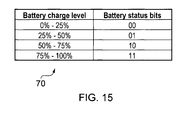
- Figure 15 is a table 70 demonstrating an example of battery bits that can be used in a control field of a transmission frame to denote battery charge level. The percentage charge is divided into four different levels each with a range of 25%. Alternatively fewer or more levels may be chosen and the scale need not be divided linearly. For example, the top charge level may be of 50 to 100% for example and other charge levels may cover a smaller range. As for the urgency bits, two bits are used, allowing division of the battery charge into four different levels.
- Figure 16 is a flow diagram showing signal flow between a device and a coordinator with a changing parameter value and changing battery charge status. Such embodiments can be useful in medical telemetry applications in which urgent medical assistance may not be available.
- the battery level can be included in the sleep pattern control to make sure that higher duty cycle sleep patterns do not lead to complete depletion of the battery charge.
- a higher duty cycle pattern which is suitable given the parameter values measured can only be implemented if the battery level is appropriate. Otherwise, the current sleep pattern is maintained. Equally, if the battery level falls, a lower duty-cycle than that suitable for the parameter values measured may need to be selected.
- urgency bits 01 as set out in Table 1 may be transmitted in one or more current transmission frames.
- the sensor measures a parameter such as glucose level.
- the sensor sends the parameter to the coordinator in step S301 and the coordinator assesses the patient situation in step S302. If there is a heightened level of emergency, urgency bits 10 are sent to the sensor.
- the sensor checks the battery level S304 to determine whether the sleep pattern indicated by these urgency bits is allowable. If it is not, the sensor sends a battery low message to the coordinator in step S305, for example using battery bits 01. The coordinator then takes action S306 on the battery.
- step S308 the sensor updates the parameter values being sent to the coordinator which leads a higher emergency state being detected by the coordinator in step S308.
- the coordinator sends urgency bits 11 to the sensor in step S309.
- step S31 0 the sensor checks to see if the battery level will allow more frequent wakeups. If so the sleep pattern is changed to correspond to the urgency bits 11 in step S311.
- the sensor transition to the emergency state leads to the number of devices in an emergency crossing in a threshold.
- a coordinator takes action in step S312 by sending urgency bits 00 to non-critical medical devices to slow their wake up pattern in step S313.
- step S314 the coordinator sends urgency bits indicating the slowest suitable wakeup pattern to non-medical devices (although these are shown as bits 00, and do not fit into the scheme of Table 1, the skilled reader will appreciate how to use more bits or other methodology to indicate a further sleep pattern).
- Figure 17 shows an equivalent scenario in which the central care unit is in control of the processing and decisions and the coordinator acts as a relay, with the exception of the battery action, which is handled by the coordinator without necessarily passing the battery low bits on to the central monitoring unit.
- Figure 18 is a table 70 demonstrating one way of associating sleep patterns to levels of battery charge.
- the sleep patterns shown may be for a single category of device so that the division into medical and non-medical devices shown in the previous Figures and Table 1 is no longer applicable.
- the lowest level ⁇ 1 (0 to 25%) only allows a low wake up sleep pattern whatever the outcome of the threshold comparison; the second level L2 additionally allows a medium wake up pattern; the third level L3 (50 to 75%) additionally allows a higher wake up pattern and the top level L4 (75 to 100%) additionally allows a continuous wake up pattern so that all the possible sleep patterns are permitted.
- the battery charge level overrides a sleep pattern selected according to parameter values if necessary.
- Figure 19 is a flow diagram showing another method in a device of selecting a sleep pattern without considering battery level.
- the coordinator sends frames with urgency bits which are set according to Table 2 shown below.
- Table 2 sleep patterns and urgency bits in a network of devices of the same type Urgent bits: u1u2 Urgency level Upper threshold Sleep/wake up pattern 00 Device in Normal Condition Th1 Normal sleep/wake up pattern; Longest Sleep Time, very low duty cycle 01 Device in Slightly Abnormal condition Th2 Slightly Abnormal Sleep/wake up Pattern; Slight increase of duty cycle 10 Device in Abnormal condition Th3 Abnormal Sleep/wake up Pattern; increase of duty cycle 11 Device in Emergency Emergency Sleep/wake up Pattern; dramatic increase of duty or cycle or continuous wake up
- the coordinator sends urgency bits 00 (with parameter values up to threshold Th1). With a slight abnormality, urgency bits 01 (from Th1 up to threshold Th2 of the measured parameter) are sent. In abnormal conditions up to threshold Th3 of the measured parameter the device sends urgency bits 10. From measured parameter values of Th3 upwards, the device is in emergency and sends urgency bits 11.
- parameter values are measured S400 and sent S401 to the coordinator.
- the coordinator assesses the urgency of the situation by comparing the values against thresholds Th1 to Th3. If the device is in a normal situation, there is no change S402 in the sleep pattern. In a slightly abnormal situation defined between thresholds Th1 and Th2, the coordinator selects a different suitable sleep pattern with an indication of the new sleep pattern sent S403 to the sensor as bits 01. The sensor undergoes an increase S404 in the duty cycle. If the parameter falls between the second and third thresholds Th2 and Th3, the device is in an abnormal situation, and the corresponding message is sent S405 from the coordinator with urgency bits 10.
- the sleep pattern is changed S406 again to reflect the abnormal situation. Finally, if the measured parameter is above parameter Th3, the device is in an emergency and a message with urgency bits 11 is sent S407 by the coordinator. The sensor changes S408 its duty cycle again to the highest level.
- a message is sent S412 to one or more non-medical devices, causing them to reduce S413 their sleep pattern, for example to the lowest level.
- equivalent message S410 is set to cause non-critical medical devices to lower their duty cycle.
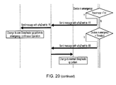
- FIG 20 is an equivalent diagram to Figure 19 , in which the central monitoring unit carries out the processing and control signalling handled by the coordinator in Figure 19 .
- the coordinator simply acts as a relay.
- FIG 21 is the corresponding flow diagram to Figure 19 with the battery level now being taken into consideration.
- battery bits are transmitted from the sensor and urgent bits are transmitted from the coordinator.
- the urgency bits sent by the coordinator indicate a suitable sleep pattern taking the parameter measurement only into account and the battery bits sent by the sensor show the actual sleep pattern in operation, which is the maximum allowed sleep pattern.
- the coordinator assesses the parameter to see if it falls below Th1, between Th1 and Th2, between Th2 and Th3, or above Th3. If the parameter is below Th1 no change S501 in the sleep wake up pattern is required.
- a message is sent to the sensor in step S502 with urgency bits set to 01.
- the battery level is checked S503. If the sleep pattern selected by this parameter measurement is allowed by the control means in accordance with the table in Figure 18 (that is, in this case, if the battery charge is at L2, L3 or L4) the sleep pattern is changed S504 to slightly abnormal. If the battery is at L1, there can be no change of sleep pattern but a message is sent S505 to the coordinator with the battery bits are set to 00 to reflect the battery level L1. The coordinator takes action S506 on the low battery.
- the sleep pattern is changed S507 to the maximum level allowed by the battery and a message is sent to the coordinator in step S508 with the battery bits set to xx, which is the battery level for the maximum allowed sleep-wake up pattern. If the battery level is ok for a device in a slightly abnormal situation, this would cover levels L2, L3 and L4. Thus the only other alternative is that the battery level is L1. However, for ease of implementation, this extra step may be included for this parameter level as for the other parameter levels. Otherwise it may be omitted.
- a message is sent to the sensor to indicate a suitable sleep pattern with urgency bits 10.
- the battery level is again checked to see if it is acceptable. If it is ok for the required sleep pattern change (that is at L3 or L4), the device changes to an abnormal sleep pattern. If on the other hand the battery level is at L1, no change to the sleep pattern is available and a message is sent to the coordinator with the battery bits are set to 00. Action on the battery is taken. Otherwise, (if the battery level is at L2) the sleep pattern is changed to the maximum allowed by the battery (01) and a message is sent with the battery bits set to xx which is the maximum allowed sleep pattern channel access is adjusted. Here xx is 01, to reflect level L2.
- a message with the urgency bits set to 11 is set to the sensor and the battery level is checked. It is only ok if it is at level L4. In this case the device changes its own sleep pattern to emergency. On the other hand if the battery level is at L1, a message is sent to the coordinator with the battery bits set to 00. For any other level (here levels L2 and L3) the sleep pattern is changed to the maximum pattern allowed and battery bits sent are set to xx, being the maximum allowed sleep pattern (that is, the implemented sleep pattern) as before.
- this information is used to check how many devices are in an emergency state. If the number of devices has exceeded a threshold, then action is taken to send a message with urgency bits set 200 to non-critical medical devices and non-medical devices. These devices then change to a normal (lowest) duty cycle sleep pattern.
- Figure 22 is an equivalent diagram to Figure 21 but shows the comparison functionality and setting of urgency bits carried out by the central monitoring and medical care unit.
- the coordinator functions only as a relay, apart from its role in taking action on the battery. Thus all the messages sent from the sensor with respect to battery levels are handled by the coordinator and not necessarily forwarded to the central unit.
- the battery bits can be used separately from the parameter measurement, purely as an indicator of battery level.
- the co-ordinator can then calculate the actual sleep pattern implemented from the combination of the battery bits, a look up table and the parameter values or the suitable sleep pattern it has transmitted to the sensor. This alternative gives more detailed information about battery levels but requires increased processing capability at the co-ordinator.
- Figure 23 illustrates a modification to the IEEE 802.15.4 frame format to indicate urgency of the message so that the urgent message is assigned high priority over others.
- Two urgency bits 81, 82 are shown and are employed by the sensor in transmission frames such as any or all of data frames, acknowledgement frames and MAC command frames to indicate the changing suitable sleep pattern by the coordinator to the sensor.
- urgency bits can also be used to differentiate between non-medical and medical devices as shown for example in Table 1 or for differentiation of priority between different device types in an industrial application.
- the frame control is extended by one octet in which two bits (urgency U1 and urgency U2) are used to indicate different levels of urgencies which correspond to different sleep patterns.
- Figure 24 additionally includes two bits 83, 84 related to the battery level.
- the bits are shown as battery level 1, L1 and level 2, L2.
- the urgency bits transmitted to the sensor may not be reflected in an actual sleep pattern implemented by the sensor, because the suitable sleep pattern is not allowed due to battery level considerations.
- the battery bits sent to the coordinator may then need to be viewed in conjunction with the parameter level/urgency bits as an indication of the actual sleep pattern implemented, taking the battery level into account.
- This sleep pattern enhancement may be one of a number of linked enhancements.
- Figure 25 shows the required modifications to IEEE 802.15.4 frame control fields to include the urgency bits and battery bits referred to herein, along with an emergency bit and two bits denoting an acknowledgement type.
- the reserved bits (7-9) of IEEE 802.15.4 are used for these emergency and acknowledgement types.
- the frame control has been extended by one octet of which two bits are used to distinguish various levels of urgency and an another two battery bits as used as explained hereinbefore. The remaining two bits of the octet are reserved.
- the corresponding IEEE 802.15.4 modified frame type is shown in Figure 26 .
- reserved bits 100-111 are used to indicate the different type of ACK frames and an emergency frame which is a new type of frame created for emergency situations.
- the enhancements would possibly include in the frame control the following:
- Figure 27 illustrates the enhancements as part of a new standard such as IEEE 802.15.6.
- the Figure illustrates the proposed part of the header frame at the MAC layer.
- the urgency levels and battery levels refer to the embodiments of the present application, which may be combined with any combination of the other enhancements to form further embodiments in a complete system.
- an emergency bit (or other emergency indication) used in conjunction with urgency bits and optionally battery level bits (suitable sleep pattern indication and optionally battery charge information) can supplement and/or confirm emergency status.
- Figure 28 shows a table corresponding to Figure 27 of possible frame type bits.
- Figure 29 illustrates the basic format of a MAC frame in the current IEEE 802.15.4 standard indicating the location of the MAC Command octets.
- Figure 30 illustrates the Command Frame Identifier list of the current version of IEEE 802.15.4 standard.
- the frame control embodiments of the present invention described above use at least four bits (u1 u2 b1 b2) in the MAC frame control of the MAC frame header to specify the states of a BAN device.
- These state information bits can all be set independently and combined in multiple ways for BAN, BAN traffic, and BAN device management, generally in, but not limited to, emergency situations. They may be sent in a MAC command frame as shown in Figure 29 , or any other type of transmission frame.
- a new MAC command frame can be added, with a new command frame identifier added to the list in Figure 30 .
- the payload could be used to differentiate between device states using the bits previously mentioned or in some other way.
- a further alternative and preferable approach suitable for any transmission frame type including MAC command frames is to introduce a single octet outside the frame control but still in the MAC Header with the bits previously mentioned, or preferably an enumerated list of device states as shown below.
- This octet will provide a total of 256 possible device states, for example, but not limited to:
- Embodiments of the invention disclose a novel coordinator-based centralized sleep/wake-up pattern scheduling that allows the coordinator in a medical BAN to harmonise the sleep patterns under emergency conditions considering the number of devices in emergency.
- the invention embodiments consider the cases in which a central monitoring capability is available and the sleep pattern can be changed by a nurse from central care station analysing the patient situation or on an automatic basis based on an analysis or diagnosis performed in a central monitoring station.
- a particularly advantageous feature is creating centralised command capability to change the sleep pattern using medical staff analysing the situation considering multiple input parameters. This may also be done in a gateway or elsewhere by some intelligent pattern recognition algorithms.
- They provide methods for centralized sleep pattern scheduling in a Medical Body Area Network or a Wireless Sensor Network in Response to an emergency situation and in harmony with the central medical care unit.
- Novel signalling bits i.e. emergency bits
- Novel signalling bits are provided to quantize the amount of slow-down in the wake-up pattern
- Embodiments of the present invention may have a vital role to play in facilitating emergency management by use of MBANs.
- the following scenarios may be noted:
- the present invention may take the form of a novel sensor, coordinator, central monitoring unit, or hardware modules for the same, and can be implemented by replacing or modifying software executed by processors of the sensor(s) and/or the coordinator and/or central monitoring unit.
- embodiments of the present invention may be implemented in hardware, or as software modules running on one or more processors, or on a combination thereof.
- the invention may also be embodied as one or more device or apparatus programs (e.g. computer programs and computer program products) for carrying out part or all of any of the techniques described herein.
- Such programs embodying the present invention may be stored on computer-readable media, or could, for example, be in the form of one or more signals.
- signals may be data signals downloadable from an Internet website, or provided on a carrier signal, or in any other form.
- IEEE 802.15.4 and IEEE 802.15.6 by way of example, the invention may be applied to any type of MBAN whether or not operating in accordance with IEEE 802.15.6, as well as to other types of BAN and other short-range WSNs which even if not medical body area networks nevertheless have a requirement for improved reliability of communication in emergency situations.
Landscapes
- Engineering & Computer Science (AREA)
- Computer Networks & Wireless Communication (AREA)
- Signal Processing (AREA)
- Mobile Radio Communication Systems (AREA)
- Telephonic Communication Services (AREA)
Claims (14)
- Drahtloses Sensornetzwerk von Einrichtungen, das einen Sensor (60) und einen Koordinator (64) aufweist, wobei der Sensor aufweist:Messwertaufnahmemittel (61), die in der Lage sind, Werte eines Parameters zu ermitteln; Übertragungs-und Empfangsmittel (62) für die drahtlose Kommunikation mit anderen Einrichtungen im Netzwerk; und Sensor-Steuerungsmittel (63), die in der Lage sind, ein Schlafmuster des Sensors zu steuern, undwobei der Koordinator Übertragungs- und Empfangsmittel für die drahtlose Kommunikation mit anderen Einrichtungen im Netzwerk aufweist, wobeimehrere vorher festgelegte Schlafmuster bereitgestellt werden, wobei die Auswahl eines geeigneten Schlafmusters in Übereinstimmung mit Parameterwert-Schwellenwerten getroffen wird, wobei jeder Schwellenwert eine Grenze zwischen Schlafmustern mit einem niedrigeren Wake-Up und einem höheren Wake-Up festlegt und wobeidie Sensor-Übertragungsmittel in der Lage sind, Werteinformationen in Bezug auf die Parameterwerte zu übertragen, und die Koordinator-Übertragungsmittel in der Lage sind, eine Anzeige eines geeigneten Sensor-Schlafmusters zu übermitteln, das durch Vergleich der übertragenen Werteinformationen mit den Schwellenwerten für die Parameter zentral bestimmt wurde.
- Netzwerk nach Anspruch 1, wobei der Sensor (60) eine von mehreren betriebszyklisch arbeitenden Einrichtungen im Netzwerk ist, wobei der Koordinator (64) in der Lage ist, für jede der betriebszyklisch arbeitenden Einrichtungen geeignete Schlafmuster zu übertragen und wobei vorzugsweise das geeignete Schlafmuster, das mindestens einer der betriebszyklisch arbeitenden Einrichtungen übermittelt wurde, zusätzlich mindestens einen äußeren Faktor berücksichtigt, der nicht auf diese Einrichtung bezogen ist.
- Netzwerk nach Anspruch 2, wobei ein derartiger äußerer Faktor auf den Werteinformationen basiert.
- Netzwerk nach Anspruch 2 oder 3, wobei das geeignete Schlafmuster, das der mindestens einen von den betriebszyklisch arbeitenden Einrichtungen übermittelt wurde, als einen äußeren Faktor die Anzahl der anderen Einrichtungen im Netzwerk in einem vorher festgelegten Gefahrenzustand berücksichtigt.
- Netzwerk nach Anspruch 2, 3 oder 4, wobei jede betriebszyklisch arbeitende Einrichtung eine Wertigkeit aufweist, die festlegt, in welchem Umfang, wenn überhaupt, der Koordinator irgendwelche äußeren Faktoren zur Bestimmung ihres geeigneten Schlafmusters berücksichtigt.
- Netzwerk nach einem der vorhergehenden Ansprüche, wobei der Koordinator (64) ferner Bestimmungsmittel aufweist, die in der Lage sind, das geeignete Schlafmuster zu bestimmen, oder wobei die Koordinator-Empfangsmittel in der Lage sind, das geeignete Schlafmuster aus einer zentralen Überwachungseinheit zu empfangen, die in einer drahtgebundenen oder drahtlosen Kommunikation mit dem Koordinator ist.
- Netzwerk nach einem der vorhergehenden Ansprüche, wobei die Koordinator-Übertragungsmittel in der Lage sind, die Anzeige in mindestens einem Steuerungsfeld eines Übertragungsrahmens zu übertragen, wobei vorzugsweise eine Wertemenge in dem MAC-Kopfteil, wie z.B. in dem Rahmen-Steuerfeld zu einem vorgegebenen Wert, verwendet wird.
- Netzwerk nach einem der vorhergehenden Ansprüche, wobei der Sensor (60) ferner eine Batterie aufweist und wobei die Sensor-Steuerungsmittel in der Lage sind, das Schlafmuster zu steuern, wobei sowohl die Anzeige als auch eine tatsächliche Batterieladung berücksichtigt wird.
- Netzwerk nach Anspruch 8, wobei die Sensor-Steuerungsmittel (63) die geeigneten Schlafmuster entsprechend mindestens einem vorher festgelegten Grenzwert einer zulässigen Batterieladung zulassen oder zurückweisen und vorzugsweise ein beliebiges zurückgewiesenes Schlafmuster mit einem Schlafmuster mit einem niedrigeren Wake-Up überschreiben.
- Netzwerk nach Anspruch 8 oder 9, wobei die Sensor-Übertragungsmittel in der Lage sind, Batterieladungsinformationen, welche die Batterieladung betreffen, vorzugsweise in einem Steuerungsfeld eines Übertragungsrahmens in der Form einer Wertemenge im MAC-Kopfteil, wie z.B. des Rahmen-Steuerfeldes zu einem vorgegebenen Wert, zu übertragen.
- Netzwerk nach Anspruch 10, wobei die Koordinator-Empfangsmittel in der Lage sind, die Batterieladungsinformationen zu empfangen und wobei der Koordinator Antwortmittel aufweist, die in der Lage sind, auf einen vorher festgelegten Wert der Ladungsinformationen zu reagieren, indem mit Bezug auf die Batterie eine Maßnahme ergriffen wird.
- Koordinator (64) in einem drahtlosen Sensornetzwerk von Einrichtungen, das einen Sensor (60) und den Koordinator aufweist, wobei der Koordinator umfasst:Empfangsmittel, die in der Lage sind, Werteinformationen vom Sensor in Bezug auf zu die ermittelten Werte eines Parameters zu empfangen,Bestimmungsmittel, die in der Lage sind, ein geeignetes Schlafmuster für den Sensor durch Vergleich der übertragenen Werteinformationen mit Schwellenwerten für den Parameter zu bestimmen, wobeimehrere vorher festgelegte Schlafmuster bereitgestellt werden, wobei die Auswahl eines geeigneten Schlafmusters in Übereinstimmung mit den Parameterwert-Schwellenwerten getroffen wird, wobei jeder Schwellenwert eine Grenze zwischen Schlafmustern mit einem niedrigeren Wake-Up und einem höheren Wake-Up festlegt unddie Übertragungsmittel in der Lage sind, eine Anzeige des geeigneten Schlafmusters zu übermitteln.
- Zentrale Überwachungseinheit, die in einer drahtgebundenen oder drahtlosen Kommunikation mit einem Koordinator in einem drahtlosen Sensornetzwerk von Einrichtungen ist, das einen Sensor und den Koordinator aufweist,
wobei die zentrale Überwachungseinheit umfasst:Bestimmungsmittel, die in der Lage sind, ein geeignetes Schlafmuster für den Sensor durch Vergleich von Werteinformationen in Bezug auf Parameterwerte, die durch den Sensor übermittelt wurden, mit Schwellenwerten für den Parameter zu bestimmen, nachdem der Sensor die Parameterwerte ermittelt hat, undKommunikationsmittel, die in der Lage sind, eine Anzeige des geeigneten Sensor-Schlafmusters an eine Einrichtung des Netzwerks zu senden, wobeimehrere vorher festgelegte Schlafmuster bereitgestellt werden, wobei die Auswahl eines geeigneten Schlafmusters in Übereinstimmung mit Parameterwert-Schwellenwerten getroffen wird, wobei jeder Schwellenwert eine Grenze zwischen Schlafmustern mit einem niedrigeren Wake-Up und einem höheren Wake-Up festlegt. - Verfahren in einem drahtlosen Sensornetzwerk von Einrichtungen, das einen Sensor und den Koordinator aufweist, wobei das Verfahren umfasst:Ermitteln eines Parameters im Sensor, Übermitteln von Werteinformationen in Bezug auf die Parameterwerte vom Sensor aus zum Koordinator hin, Übermitteln einer Anzeige eines geeigneten Sensor-Schlafmusters, das zentral durch Vergleich der übermittelten Werteinformationen mit Schwellenwerten für den Parameter bestimmt wurde, vom Koordinator aus zum Sensor hin und Steuern eines Schlafmusters des Sensors, indem die Anzeige berücksichtigt wird, wobeimehrere vorher festgelegte Schlafmuster bereitgestellt werden, wobei die Auswahl eines geeigneten Schlafmusters in Übereinstimmung mit Parameterwert-Schwellenwerten getroffen wird, wobei jeder Schwellenwert eine Grenze zwischen Schlafmustern mit einem niedrigeren Wake-Up und einem höheren Wake-Up festlegt.
Priority Applications (7)
| Application Number | Priority Date | Filing Date | Title |
|---|---|---|---|
| EP09154363.7A EP2227065B1 (de) | 2009-03-04 | 2009-03-04 | Verbesserungen an drahtlosen Netzen mit kurzer Reichweite |
| TW099102812A TWI437846B (zh) | 2009-03-04 | 2010-02-01 | 短距離無線網路之改進技術 |
| US13/254,088 US9736884B2 (en) | 2009-03-04 | 2010-02-09 | Improvements to short-range wireless networks |
| KR1020117023343A KR101350527B1 (ko) | 2009-03-04 | 2010-02-09 | 단거리 무선 네트워크들에 대한 향상들 |
| PCT/EP2010/051591 WO2010100012A1 (en) | 2009-03-04 | 2010-02-09 | Improvements to short-range wireless networks |
| CN201080011124.XA CN102342171B (zh) | 2009-03-04 | 2010-02-09 | 对短程无线网络的改进 |
| JP2011552376A JP5545302B2 (ja) | 2009-03-04 | 2010-02-09 | 近距離無線ネットワークの改善 |
Applications Claiming Priority (1)
| Application Number | Priority Date | Filing Date | Title |
|---|---|---|---|
| EP09154363.7A EP2227065B1 (de) | 2009-03-04 | 2009-03-04 | Verbesserungen an drahtlosen Netzen mit kurzer Reichweite |
Publications (2)
| Publication Number | Publication Date |
|---|---|
| EP2227065A1 EP2227065A1 (de) | 2010-09-08 |
| EP2227065B1 true EP2227065B1 (de) | 2015-02-18 |
Family
ID=41110376
Family Applications (1)
| Application Number | Title | Priority Date | Filing Date |
|---|---|---|---|
| EP09154363.7A Expired - Fee Related EP2227065B1 (de) | 2009-03-04 | 2009-03-04 | Verbesserungen an drahtlosen Netzen mit kurzer Reichweite |
Country Status (7)
| Country | Link |
|---|---|
| US (1) | US9736884B2 (de) |
| EP (1) | EP2227065B1 (de) |
| JP (1) | JP5545302B2 (de) |
| KR (1) | KR101350527B1 (de) |
| CN (1) | CN102342171B (de) |
| TW (1) | TWI437846B (de) |
| WO (1) | WO2010100012A1 (de) |
Families Citing this family (20)
| Publication number | Priority date | Publication date | Assignee | Title |
|---|---|---|---|---|
| KR101179126B1 (ko) * | 2010-03-31 | 2012-09-07 | 전자부품연구원 | 자기장 통신 방법 및 이에 의해 동작하는 노드 |
| CN101959295B (zh) * | 2010-09-21 | 2015-06-03 | 中兴通讯股份有限公司 | 无线传感器网络的节能管理方法、系统及远程管理服务器 |
| RU2596879C2 (ru) * | 2010-11-08 | 2016-09-10 | Конинклейке Филипс Электроникс Н.В. | Система и способ обмена информацией о рабочем цикле в беспроводных сетях |
| US20120147800A1 (en) * | 2010-12-10 | 2012-06-14 | Minyoung Park | Power management in a wireless network having stations with different power capabilities |
| US9301248B2 (en) * | 2010-12-20 | 2016-03-29 | Alcatel Lucent | Methods and apparatuses for communication in a personal area network |
| KR20130005193A (ko) * | 2011-07-05 | 2013-01-15 | 삼성전자주식회사 | Ban 환경에서의 프록시 통신 시스템 및 그 제어 방법 |
| CN102892206B (zh) * | 2011-07-20 | 2014-12-31 | 上海交通大学 | 认知无线传感器网络中基于网络特性的单天线mac传输方法 |
| US9300442B2 (en) * | 2011-07-21 | 2016-03-29 | Qualcomm Incorporated | Allowing a rejected wireless communication device access to a communication channel |
| US9510282B2 (en) * | 2011-09-09 | 2016-11-29 | Koninklijke Philips N.V. | MAC enhancement to support multi-periodic GTS allocation for personal area network (PAN) systems |
| EP2685744B1 (de) * | 2012-07-12 | 2018-05-23 | ABB Research Ltd. | Verfahren und Sensorknotennetzwerkschnittstellensystem zur drahtlosen Steuerung eines Industrieverfahrens |
| CN102984791B (zh) * | 2012-12-11 | 2016-01-13 | 清华大学 | 一种无线传感器节点的节能方法 |
| US10025905B2 (en) | 2013-09-03 | 2018-07-17 | Qualcomm Incorporated | Communication device resource allocation based on medical data criticality and resource status |
| US20150173116A1 (en) * | 2013-12-13 | 2015-06-18 | Mediatek Inc. | Communications method, device and system |
| JP6221879B2 (ja) * | 2014-03-25 | 2017-11-01 | 株式会社豊田自動織機 | 電池監視装置 |
| US10271283B2 (en) * | 2015-05-13 | 2019-04-23 | Apple Inc. | Apparatus, systems and methods for power management in mobile devices |
| CN106550437B (zh) * | 2015-09-21 | 2021-03-26 | 浙江吉利控股集团有限公司 | 降低ZigBee网络系统耗能的装置及方法 |
| KR20200087619A (ko) * | 2019-01-11 | 2020-07-21 | 삼성전자주식회사 | 무선 통신 시스템에서 단말 지원 정보 송수신 방법 및 장치 |
| CN109951894A (zh) * | 2019-05-14 | 2019-06-28 | 广东工业大学 | 一种休眠调度方法、装置、设备及介质 |
| DE102020116492A1 (de) * | 2020-06-23 | 2021-12-23 | Insta Gmbh | Verfahren zum Übertragen von Daten innerhalb eines zumindest teilweise funkbasierten Gebäudeinstallationssystems sowie Gebäudeinstallationssystem |
| CN113840388B (zh) * | 2021-10-22 | 2024-03-22 | 普联技术有限公司 | Zigbee与Wifi共存的通信方法及通信设备 |
Citations (1)
| Publication number | Priority date | Publication date | Assignee | Title |
|---|---|---|---|---|
| WO2006038163A1 (en) * | 2004-10-01 | 2006-04-13 | Nortel Networks Limited | Segmentation and clustering in a sensor network |
Family Cites Families (30)
| Publication number | Priority date | Publication date | Assignee | Title |
|---|---|---|---|---|
| JPH05316120A (ja) | 1991-11-29 | 1993-11-26 | Hitachi Inf & Control Syst Inc | ネットワーク送出データ量制御方法及びネットワーク システム |
| US20010030468A1 (en) * | 1999-12-16 | 2001-10-18 | Anderson George A. | Method and apparatus utilized for priority sequencing |
| JP2003272079A (ja) | 2002-03-13 | 2003-09-26 | Toyota Central Res & Dev Lab Inc | センサネットワーク |
| GB0211644D0 (en) * | 2002-05-21 | 2002-07-03 | Wesby Philip B | System and method for remote asset management |
| JP2004272506A (ja) | 2003-03-07 | 2004-09-30 | Japan Radio Co Ltd | センサデータ伝送システム及びその観測局装置 |
| US7356561B2 (en) | 2003-05-01 | 2008-04-08 | Lucent Technologies Inc. | Adaptive sleeping and awakening protocol for an energy-efficient adhoc network |
| US7743151B2 (en) * | 2004-08-05 | 2010-06-22 | Cardiac Pacemakers, Inc. | System and method for providing digital data communications over a wireless intra-body network |
| JP2006129102A (ja) | 2004-10-29 | 2006-05-18 | Hitachi Ltd | 通信方法 |
| JP2006186891A (ja) | 2004-12-28 | 2006-07-13 | Sanyo Electric Co Ltd | データ収集システム |
| JP2006297068A (ja) * | 2005-03-25 | 2006-11-02 | Semiconductor Energy Lab Co Ltd | 監視装置、被介護者監視装置、介護管理装置、介護者端末装置、および、それらを用いた介護支援システム、ならびに、介護支援方法 |
| US8979756B2 (en) * | 2005-05-06 | 2015-03-17 | Koninklijke Philips N.V. | Wireless medical monitoring device |
| US7242920B2 (en) * | 2005-05-31 | 2007-07-10 | Scenera Technologies, Llc | Methods, systems, and computer program products for controlling data transmission based on power cost |
| KR100717962B1 (ko) * | 2005-07-15 | 2007-05-14 | 전자부품연구원 | 다수의 노드를 포함하는 무선 네트워크 시스템에서의데이터 전송 제어 방법 및 이를 이용한 센서 네트워크시스템 및 기록 매체 |
| US20070027367A1 (en) * | 2005-08-01 | 2007-02-01 | Microsoft Corporation | Mobile, personal, and non-intrusive health monitoring and analysis system |
| JP4213151B2 (ja) * | 2005-09-07 | 2009-01-21 | 俊彦 水上 | Gps機能付き携帯通信端末 |
| JP2009086697A (ja) * | 2006-01-18 | 2009-04-23 | Osaka Univ | 無線センサネットワークおよびその情報伝達方法 |
| US8018884B2 (en) * | 2006-06-21 | 2011-09-13 | Qualcomm Incorporated | Low duty cycle network controller |
| US20080025341A1 (en) * | 2006-07-31 | 2008-01-31 | Motorola, Inc. | Method and system for granting of channel slots |
| US7746222B2 (en) * | 2006-10-23 | 2010-06-29 | Robert Bosch Gmbh | Method and apparatus for installing a wireless security system |
| US8149748B2 (en) * | 2006-11-14 | 2012-04-03 | Raytheon Company | Wireless data networking |
| US8073554B2 (en) * | 2006-12-20 | 2011-12-06 | Nortel Networks Limited | System and method for providing power management in a sensor network |
| CN101657148A (zh) * | 2007-04-24 | 2010-02-24 | 光纤技术株式会社 | 生体信息检测装置 |
| JP2008278308A (ja) * | 2007-05-01 | 2008-11-13 | Ntt Communications Kk | 無線通信システムおよび無線端末装置 |
| US8208391B2 (en) * | 2007-11-30 | 2012-06-26 | Motorola Solutions, Inc. | Method and apparatus for operating a node within a mobile ad hoc cognitive radio network |
| KR101456057B1 (ko) * | 2007-12-27 | 2014-11-03 | 삼성전자주식회사 | 무선 센서 네트워크 및 이의 관리 방법 |
| JP4722144B2 (ja) | 2008-01-10 | 2011-07-13 | 三菱電機株式会社 | レーダ装置 |
| US8259648B2 (en) * | 2008-01-18 | 2012-09-04 | General Electric Company | Enhanced communication of data in wireless control area networks |
| CN101282335B (zh) | 2008-05-20 | 2012-09-05 | 浙江大学宁波理工学院 | 低负载无线传感器网络mac层监听休眠方法 |
| WO2009144731A2 (en) * | 2008-05-28 | 2009-12-03 | Oridion Medical 1987 Ltd. | Methods, apparatus and systems for monitoring co2 |
| US8576760B2 (en) * | 2008-09-12 | 2013-11-05 | Qualcomm Incorporated | Apparatus and methods for controlling an idle mode in a wireless device |
-
2009
- 2009-03-04 EP EP09154363.7A patent/EP2227065B1/de not_active Expired - Fee Related
-
2010
- 2010-02-01 TW TW099102812A patent/TWI437846B/zh not_active IP Right Cessation
- 2010-02-09 US US13/254,088 patent/US9736884B2/en not_active Expired - Fee Related
- 2010-02-09 CN CN201080011124.XA patent/CN102342171B/zh not_active Expired - Fee Related
- 2010-02-09 WO PCT/EP2010/051591 patent/WO2010100012A1/en active Application Filing
- 2010-02-09 JP JP2011552376A patent/JP5545302B2/ja not_active Expired - Fee Related
- 2010-02-09 KR KR1020117023343A patent/KR101350527B1/ko not_active IP Right Cessation
Patent Citations (1)
| Publication number | Priority date | Publication date | Assignee | Title |
|---|---|---|---|---|
| WO2006038163A1 (en) * | 2004-10-01 | 2006-04-13 | Nortel Networks Limited | Segmentation and clustering in a sensor network |
Also Published As
| Publication number | Publication date |
|---|---|
| TW201129014A (en) | 2011-08-16 |
| US9736884B2 (en) | 2017-08-15 |
| JP5545302B2 (ja) | 2014-07-09 |
| CN102342171B (zh) | 2015-04-01 |
| US20120057486A1 (en) | 2012-03-08 |
| WO2010100012A1 (en) | 2010-09-10 |
| KR101350527B1 (ko) | 2014-01-10 |
| KR20110134450A (ko) | 2011-12-14 |
| EP2227065A1 (de) | 2010-09-08 |
| CN102342171A (zh) | 2012-02-01 |
| TWI437846B (zh) | 2014-05-11 |
| JP2012519438A (ja) | 2012-08-23 |
Similar Documents
| Publication | Publication Date | Title |
|---|---|---|
| EP2227065B1 (de) | Verbesserungen an drahtlosen Netzen mit kurzer Reichweite | |
| US8825120B2 (en) | Short range wireless networks | |
| EP2227062B1 (de) | Verbesserungen an drahtlosen Netzen mit kurzer Reichweite | |
| EP2226002B1 (de) | Verbesserungen an körpernahen Netzen | |
| KR101439592B1 (ko) | 신체 영역 네트워크에 대한 개선 | |
| US9072114B2 (en) | Improvements to body area networks | |
| KR101304780B1 (ko) | 단거리 무선 네트워크들에 대한 향상들 | |
| EP2226958A1 (de) | Drahtlose Sensornetzwerke mit Datenempfangsquittierung |
Legal Events
| Date | Code | Title | Description |
|---|---|---|---|
| PUAI | Public reference made under article 153(3) epc to a published international application that has entered the european phase |
Free format text: ORIGINAL CODE: 0009012 |
|
| AK | Designated contracting states |
Kind code of ref document: A1 Designated state(s): AT BE BG CH CY CZ DE DK EE ES FI FR GB GR HR HU IE IS IT LI LT LU LV MC MK MT NL NO PL PT RO SE SI SK TR |
|
| AX | Request for extension of the european patent |
Extension state: AL BA RS |
|
| 17P | Request for examination filed |
Effective date: 20100831 |
|
| AKX | Designation fees paid |
Designated state(s): DE FR GB |
|
| 17Q | First examination report despatched |
Effective date: 20130212 |
|
| REG | Reference to a national code |
Ref country code: DE Ref legal event code: R079 Ref document number: 602009029397 Country of ref document: DE Free format text: PREVIOUS MAIN CLASS: H04W0084180000 Ipc: H04W0052020000 |
|
| GRAP | Despatch of communication of intention to grant a patent |
Free format text: ORIGINAL CODE: EPIDOSNIGR1 |
|
| RIC1 | Information provided on ipc code assigned before grant |
Ipc: H04W 84/18 20090101ALI20140630BHEP Ipc: H04W 52/02 20090101AFI20140630BHEP |
|
| INTG | Intention to grant announced |
Effective date: 20140725 |
|
| GRAS | Grant fee paid |
Free format text: ORIGINAL CODE: EPIDOSNIGR3 |
|
| GRAP | Despatch of communication of intention to grant a patent |
Free format text: ORIGINAL CODE: EPIDOSNIGR1 |
|
| INTG | Intention to grant announced |
Effective date: 20141202 |
|
| GRAA | (expected) grant |
Free format text: ORIGINAL CODE: 0009210 |
|
| AK | Designated contracting states |
Kind code of ref document: B1 Designated state(s): DE FR GB |
|
| REG | Reference to a national code |
Ref country code: GB Ref legal event code: FG4D |
|
| REG | Reference to a national code |
Ref country code: DE Ref legal event code: R096 Ref document number: 602009029397 Country of ref document: DE Effective date: 20150402 |
|
| REG | Reference to a national code |
Ref country code: DE Ref legal event code: R097 Ref document number: 602009029397 Country of ref document: DE |
|
| PLBE | No opposition filed within time limit |
Free format text: ORIGINAL CODE: 0009261 |
|
| STAA | Information on the status of an ep patent application or granted ep patent |
Free format text: STATUS: NO OPPOSITION FILED WITHIN TIME LIMIT |
|
| 26N | No opposition filed |
Effective date: 20151119 |
|
| REG | Reference to a national code |
Ref country code: FR Ref legal event code: PLFP Year of fee payment: 8 |
|
| REG | Reference to a national code |
Ref country code: FR Ref legal event code: PLFP Year of fee payment: 9 |
|
| PGFP | Annual fee paid to national office [announced via postgrant information from national office to epo] |
Ref country code: FR Payment date: 20170213 Year of fee payment: 9 Ref country code: DE Payment date: 20170228 Year of fee payment: 9 |
|
| PGFP | Annual fee paid to national office [announced via postgrant information from national office to epo] |
Ref country code: GB Payment date: 20170301 Year of fee payment: 9 |
|
| REG | Reference to a national code |
Ref country code: DE Ref legal event code: R119 Ref document number: 602009029397 Country of ref document: DE |
|
| GBPC | Gb: european patent ceased through non-payment of renewal fee |
Effective date: 20180304 |
|
| PG25 | Lapsed in a contracting state [announced via postgrant information from national office to epo] |
Ref country code: DE Free format text: LAPSE BECAUSE OF NON-PAYMENT OF DUE FEES Effective date: 20181002 |
|
| PG25 | Lapsed in a contracting state [announced via postgrant information from national office to epo] |
Ref country code: GB Free format text: LAPSE BECAUSE OF NON-PAYMENT OF DUE FEES Effective date: 20180304 |
|
| PG25 | Lapsed in a contracting state [announced via postgrant information from national office to epo] |
Ref country code: FR Free format text: LAPSE BECAUSE OF NON-PAYMENT OF DUE FEES Effective date: 20180331 |