EP2227010A2 - Steuereinheitvorrichtung - Google Patents
Steuereinheitvorrichtung Download PDFInfo
- Publication number
- EP2227010A2 EP2227010A2 EP10155765A EP10155765A EP2227010A2 EP 2227010 A2 EP2227010 A2 EP 2227010A2 EP 10155765 A EP10155765 A EP 10155765A EP 10155765 A EP10155765 A EP 10155765A EP 2227010 A2 EP2227010 A2 EP 2227010A2
- Authority
- EP
- European Patent Office
- Prior art keywords
- tuner
- signals
- transmitted
- control signals
- main controller
- Prior art date
- Legal status (The legal status is an assumption and is not a legal conclusion. Google has not performed a legal analysis and makes no representation as to the accuracy of the status listed.)
- Withdrawn
Links
- 238000004891 communication Methods 0.000 claims abstract description 114
- 230000005669 field effect Effects 0.000 claims abstract description 5
- 238000000034 method Methods 0.000 claims description 6
- 238000002834 transmittance Methods 0.000 description 2
- 238000010586 diagram Methods 0.000 description 1
- 229910044991 metal oxide Inorganic materials 0.000 description 1
- 150000004706 metal oxides Chemical class 0.000 description 1
- 238000012986 modification Methods 0.000 description 1
- 230000004048 modification Effects 0.000 description 1
- 230000010363 phase shift Effects 0.000 description 1
- 239000004065 semiconductor Substances 0.000 description 1
Images
Classifications
-
- H—ELECTRICITY
- H04—ELECTRIC COMMUNICATION TECHNIQUE
- H04N—PICTORIAL COMMUNICATION, e.g. TELEVISION
- H04N5/00—Details of television systems
- H04N5/44—Receiver circuitry for the reception of television signals according to analogue transmission standards
- H04N5/46—Receiver circuitry for the reception of television signals according to analogue transmission standards for receiving on more than one standard at will
-
- H—ELECTRICITY
- H04—ELECTRIC COMMUNICATION TECHNIQUE
- H04N—PICTORIAL COMMUNICATION, e.g. TELEVISION
- H04N21/00—Selective content distribution, e.g. interactive television or video on demand [VOD]
- H04N21/40—Client devices specifically adapted for the reception of or interaction with content, e.g. set-top-box [STB]; Operations thereof
- H04N21/41—Structure of client; Structure of client peripherals
- H04N21/426—Internal components of the client ; Characteristics thereof
- H04N21/42607—Internal components of the client ; Characteristics thereof for processing the incoming bitstream
- H04N21/4263—Internal components of the client ; Characteristics thereof for processing the incoming bitstream involving specific tuning arrangements, e.g. two tuners
- H04N21/42638—Internal components of the client ; Characteristics thereof for processing the incoming bitstream involving specific tuning arrangements, e.g. two tuners involving a hybrid front-end, e.g. analog and digital tuners
-
- H—ELECTRICITY
- H04—ELECTRIC COMMUNICATION TECHNIQUE
- H04N—PICTORIAL COMMUNICATION, e.g. TELEVISION
- H04N21/00—Selective content distribution, e.g. interactive television or video on demand [VOD]
- H04N21/40—Client devices specifically adapted for the reception of or interaction with content, e.g. set-top-box [STB]; Operations thereof
- H04N21/43—Processing of content or additional data, e.g. demultiplexing additional data from a digital video stream; Elementary client operations, e.g. monitoring of home network or synchronising decoder's clock; Client middleware
- H04N21/438—Interfacing the downstream path of the transmission network originating from a server, e.g. retrieving encoded video stream packets from an IP network
- H04N21/4382—Demodulation or channel decoding, e.g. QPSK demodulation
-
- H—ELECTRICITY
- H04—ELECTRIC COMMUNICATION TECHNIQUE
- H04N—PICTORIAL COMMUNICATION, e.g. TELEVISION
- H04N5/00—Details of television systems
- H04N5/44—Receiver circuitry for the reception of television signals according to analogue transmission standards
- H04N5/455—Demodulation-circuits
Definitions
- the present invention relates to a tuner unit apparatus which receives digital TV (television) signals and analog TV signals.
- tuner unit apparatus for receiving TV signals provided with a tuner which has a function to receive both digital TV signals and analog TV signals.
- tuner unit apparatus which is further provided with a main controller and a sub controller so that the main controller and the sub controller control an operation of receiving TV signals in the tuner by I2C (inter-integrated circuit) communication.
- tuner unit apparatus provided with a tuner which has a function to receive both digital TV signals and analog TV signals.
- This tuner unit apparatus has a bus switch to switch between a digital reception control line and an analog reception control line, and the analog reception control line is connected to the bus switch via a MOSFET (metal-oxide semiconductor field-effect transistor) (refer to Japanese Laid-Open Patent Publication No. 2008- 271290 , for example).
- MOSFET metal-oxide semiconductor field-effect transistor
- tuner for satellite broadcasts which is provided with a first signal processing circuit for processing analog FM (frequency modulation) signals and a second signal processing circuit for processing digital QPSK (quadrature phase shift keying) signals.
- either the first signal processing circuit or the second signal processing circuit is switched ON, and other is switched OFF (refer to Japanese Patent Publication No. 3,504,847 , for example).
- a tuner unit apparatus which has a switching circuit which selectively switches between video signals and specific screen signals in a front end of a superposed circuit (refer to Japanese Utility Model Registration No. 3,052,682 , for example).
- NTSC National Television System Committee
- ATSC Advanced Television System Committee
- This tuner unit apparatus has plural switches for switching electrical power supplied to plural processing circuits ON and OFF separately and a switch for switching between destinations of received signals (refer to Japanese Laid-Open Patent Publication No. 2006- 140846 , for example). Moreover, there is also a known tuner unit apparatus which has a function to receive both digital TV signals and analog TV signals to stop forming an operation clock in a front end when receiving the analog TV signals so that the front end is switched to sleep mode (refer to Japanese Laid-Open Patent Publication No. 2008- 135973 , for example).
- the sub controller controls an operation in a control object other than the tuner (a DAC (digital analog converter) which converts digital signals to analog signals, a scaler IC (integrated circuit) to convert resolution, an input-output selector for input-output selection of signals to an external equipment, a slicer IC to process EPG (electronic program guide) data, and a sound multiprocessing circuit to multiplex a sound, for example) while the main controller controls an operation of receiving the TV signals in the tuner, a communication by the main controller and a communication by the sub controller interfere with each other.
- the operating control of receiving the TV signals in the tuner by the main controller and the operating control in the control object other than the tuner by the sub controller cannot be simultaneously carried out.
- the present invention is to solve the problem described above, and an object of the present invention is to provide a tuner unit apparatus in which a main controller and a sub controller control an operation of receiving TV signals in a tuner by I2C communication, and a communication by the main controller and a communication by the sub controller do not interfere with each other.
- a tuner unit apparatus comprising: a main controller which transmits control signals via a first communication line; a sub controller which transmits control signals via a second communication line; a common control object which is connected to both the first communication line and the second communication line and is controlled by the main controller and the sub controller; a main control object which is connected to the first communication line and is controlled by the main controller; and a sub control object which is connected to the second communication line and is controlled by the sub controller, wherein the common control object is a tuner which receives digital TV (television) signals and outputs the received digital TV signals, and also receives analog TV signals and outputs the received analog TV signals, the main controller controls an operation of receiving the digital TV signals in the tuner and an operation in the main control object by transmitting control signals by I2C (inter-integrated circuit) communication via the first communication line, and the sub controller controls an operation of receiving the analog TV signals in the tuner and an operation in the sub control object by transmitting control signals by I2C (inter-integrated circuit) communication via the first communication
- the tuner unit apparatus further comprises: a first switching circuit which is located in the first communication line leading from the main controller to the tuner and switches modes of the control signals which are transmitted from the main controller between a mode that the control signals are transmitted to the tuner via the first communication line and a mode that the control signals are not transmitted to the tuner; and a second switching circuit which is located in the second communication line leading from the sub controller to the tuner and switches modes of the control signals which are transmitted from the sub controller between a mode that the control signals are transmitted to the tuner via the second communication line and a mode that the control signals are not transmitted to the tuner.
- the first switching circuit switches the mode so that the control signals transmitted from the main controller are not transmitted to the tuner via the first communication line when the sub controller controls the operation of receiving the analog TV signals in the tuner.
- the second switching circuit switches the mode so that the control signals transmitted from the sub controller are not transmitted to the tuner via the second communication line when the main controller controls the operation of receiving the digital TV signals in the tuner.
- the control signals transmitted from the sub controller are not transmitted to the tuner by the operation of the second switching circuit.
- the sub controller controls the operation of receiving the analog TV signals in the tuner
- the control signals transmitted from the main controller are not transmitted to the tuner by the operation of the first switching circuit.
- the main controller controls the operation of receiving the digital TV signals in the tuner
- the communication by the main controller and the communication by the sub controller do not interfere with each other
- the sub controller controls the operation of receiving the analog TV signals in the tuner
- the communication by the sub controller and the communication by the main controller do not interfere with each other. Accordingly, the operating control of receiving the digital TV signals in the tuner by the main controller and the operating control in the sub control object by the sub controller can be simultaneously carried out, and moreover, the operating control of receiving the analog TV signals in the tuner by the sub controller and the operating control in the main control object by the main controller can be simultaneously carried out.
- the first switching circuit is a demodulator which processes the digital TV signals outputted from the tuner and has a repeater function to link and transmit the control signals which are transmitted from the main controller, therein when the repeater function is switched ON and OFF (active/ inactive) by the control signals transmitted from the main controller, the demodulator switches the modes of the control signals which are transmitted from the main controller between the mode that the control signals are transmitted to the tuner via the first communication line and the mode that the control signals are not transmitted to the tuner.
- the second switching circuit is a FET (field effect transistor) circuit having a FET, therein when the FET is switched ON and OFF (conductive/ nonconductive) by the control signals transmitted from the main controller through the demodulator, the FET circuit switches the modes of the control signals which are transmitted from the sub controller between the mode that the control signals are transmitted to the tuner via the second communication line and the mode that the control signals are not transmitted to the tuner.
- FET field effect transistor
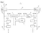
- FIG 1 shows a configuration of the tuner unit apparatus according to the present preferred embodiment.
- a tuner unit apparatus 1 receives digital TV signals and analog TV signals.
- the tuner unit apparatus 1 includes a main controller 2, a sub controller 3, a tuner 4 which is a common control object, a main control object 5 (5a, 5b, ⁇ ), a sub control object 6 (6a, 6b, ⁇ ), a demodulator 7, and a FET (field effect transistor) circuit 8.
- the main controller 2 and the sub controller 3 control the tuner unit apparatus 1.
- the main controller 2 receives operation signals (signals which indicate contents of operations of a user) inputted from an operation signal input line 29 and controls the tuner unit apparatus 1.
- the main controller 2 and the sub controller 3 communicate with each other via an inter-controller communication line 23, and the sub controller 3 receives an instruction from the main controller 2 and controls the tuner unit apparatus 1.
- the main controller 2 transmits various control signals to control the tuner unit apparatus 1 by I2C communication via a first communication line 20.
- the sub controller 3 transmits various control signals to control the tuner unit apparatus 1 by the I2C communication via a second communication line 30.
- the tuner 4 Upon receiving digital TV signals, the tuner 4 outputs the received digital TV signals, and upon receiving analog TV signals, the tuner 4 outputs the received analog TV signals.
- the tuner 4 is controlled by the main controller 2 and the sub controller 3 and is connected to both the first communication line 20 and the second communication line 30.
- the main control object 5 (5a, 5b, ⁇ ) is controlled by the main controller 2 and is connected to the first communication line 20.
- the sub control object 6 (6a, 6b, ⁇ ) is controlled by the sub controller 3 and is connected to the second communication line 30.
- the main control object 5 (5a, 5b, ⁇ ) and the sub control object 6 (6a, 6b, ⁇ ) are a DAC (digital analog converter) which converts digital signals to analog signals, a scaler IC to convert resolution, an input-output selector for input-output selection of signals to an external equipment, a slicer IC to process EPG data, and a sound multiprocessing circuit to multiplex a sound, for example.
- DAC digital analog converter
- the demodulator 7 processes the digital TV signals which are outputted from the tuner 4.
- the demodulator 7 makes up a first switching means.
- the FET circuit 8 which is located in the second communication line 30 (30a) leading from the sub controller 3 to the tuner 4, switches modes of the control signals which are transmitted from the sub controller 3 between the mode that the control signals are transmitted to the tuner 4 via the second communication line 30 and the mode that the control signals are not transmitted to the tuner 4.
- the FET circuit 8 makes up a second switching means.
- the main controller 2 transmits the control signals by the I2C communication via the first communication line 20 to control the operation of receiving the digital TV signals in the tuner 4, the operation in the main control object 5 (5a, 5b, ⁇ ), the operation in the demodulator 7, and the operation in the FET circuit 8.
- the sub controller 3 transmits the control signals by the I2C communication via the second communication line 30 to control the operation of receiving the analog TV signals in the tuner 4 and the operation in the sub control object 6 (6a, 6b, ⁇ ).
- the tuner unit apparatus 1 receives the digital TV signals and the analog TV signals.
- the digital TV signals outputted from the tuner 4 are signals which relate to images and audio and TS (Transport Stream) signals in which EPG data or the like are digitally compressed, decoded and multiplexed, for example.
- the digital TV signals outputted from the tuner 4 are expanded and demodulated in the demodulator 7 and subsequently outputted from the demodulator 7.
- Signal processing are performed on the digital TV signals which are outputted from the demodulator 7 (after being expanded and demodulated) and the analog TV signals which are outputted from the tuner 4 in various signal processor in the main control object 5 (5a, 5b, ⁇ ) and the sub control object 6 (6a, 6b, ⁇ ), and subsequently, the processed received signals are provided to a display and a speaker of an external equipment.
- the demodulator 7 has a repeater function to link and transmit the control signals which are transmitted from the main controller 2, so that when the repeater function is ON (the repeater function is active), the demodulator 7 links and transmits the control signals transmitted from the main controller 2, and when the repeater function is OFF (the repeater function is not active), the demodulator 7 does not link and transmit the control signals transmitted from the main controller 2.
- the demodulator 7 switches the mode so that the control signals transmitted from the main controller 2 are transmitted to the tuner 4 via the first communication line 20 and when the repeater function is OFF, the demodulator 7 switches the mode so that the control signals transmitted from the main controller 2 are not transmitted to the tuner 4 via the first communication line 20.
- the sub controller 3 controls the operation of receiving the analog TV signals in the tuner 4
- the demodulator 7 switches the repeater function OFF, so that the control signals transmitted from the main controller 2 are not transmitted to the tuner 4 via the first communication line 20.
- the demodulator 7 Upon receiving the control signals transmitted from the main controller 2 by the I2C communication via the first communication line 20, the demodulator 7 switches the repeater function ON and OFF. In other words, when the repeater function is switched ON and OFF by the control signals transmitted from the main controller 2, the demodulator 7 switches the modes of the control signals, which are transmitted from the main controller 2 afterward, between the mode that the control signals are transmitted to the tuner 4 via the first communication line 20 and the mode that the control signals are not transmitted to the tuner 4.
- the FET circuit 8 has a FET, so that when the FET is ON (the FET is conductive), the FET circuit 8 switches the mode so that the control signals transmitted from the sub controller 3 are transmitted to the tuner 4, and when the FET is OFF (the FET is not conductive), the FET circuit 8 switches the mode so that control signals transmitted from the sub controller 3 are not transmitted to the tuner 4.
- the main controller 2 controls the operation of receiving the digital TV signals in the tuner 4
- the FET circuit 8 switches the FET OFF, so that the control signals transmitted from the sub controller 3 are not transmitted to the tuner 4 via the second communication line 30.
- the FET circuit 8 Upon receiving the control signals which are transmitted from the main controller 2 and linked and transmitted from the demodulator 7, the FET circuit 8 switches the FET ON and OFF. In other words, when the FET is switched between ON and OFF by the control signals transmitted from the main controller 2 and linked and transmitted from the demodulator 7, the FET circuit 8 switches the modes of the control signals, which are transmitted from the sub controller 3 afterward, between the mode that the control signals are transmitted to the tuner 4 via the second communication line 30 and the mode that the control signals are not transmitted to the tuner 4.
- the tuner unit apparatus 1 operates under the control of the main controller 2 and the sub controller 3 in the manner described below in cases that (1) the operation signals which indicate that the digital TV signals are received are inputted from the operation signal input line 29 to the main controller 2 when the analog TV signals are not received, (2) the operation signals which indicate that the analog TV signals are received are inputted from the operation signal input line 29 to the main controller 2 when the digital TV signals are not received, (3) the operation signals which indicate that the digital TV signals are received are inputted from the operation signal input line 29 to the main controller 2 when the analog TV signals are received, and (4) the operation signals which indicate that the analog TV signals are received are inputted from the operation signal input line 29 to the main controller 2 when the digital TV signals are received.
- the main controller 2 firstly transmits the control signals to instruct the demodulator 7 to switch the repeater function ON via the first communication line 20. Upon receiving the control signals, the demodulator 7 switches the repeater function ON.
- the main controller 2 transmits the control signals to instruct the FET circuit 8 to switch the FET OFF via the first communication line 20.
- the demodulator 7, whose repeater function is ON links and transmits the control signals transmitted from the main controller 2 by the repeater function.
- the FET circuit 8 switches the FET OFF.
- the main controller 2 transmits the control signals to instruct the tuner 4 to receive the digital TV signals via the first communication line 20.
- the demodulator 7, whose repeater function is ON links and transmits the control signals transmitted from the main controller 2 by the repeater function.
- the tuner 4 receives the digital TV signals.
- the FET circuit 8, whose FET is OFF does not transmit the control signals transmitted from the sub controller 3.
- the main controller 2 transmits the control signals to instruct the tuner 4 to receive the digital TV signals via the first communication line 20 (that is to say, when the main controller 2 controls the operation of receiving the digital TV signals in the tuner 4), the control signals transmitted from the sub controller 3 are not transmitted to the tuner 4 even when the sub controller 3 transmits the control signals to instruct the operation in the sub control object 6 (6a, 6b, ⁇ ) via the second communication line 30.
- the main controller 2 firstly transmits the control signals to instruct the demodulator 7 to switch the repeater function ON via the first communication line 20. Upon receiving the control signals, the demodulator 7 switches the repeater function ON.
- the main controller 2 transmits the control signals to instruct the FET circuit 8 to switch the FET ON via the first communication line 20.
- the demodulator 7, whose repeater function is ON links and transmits the control signals transmitted from the main controller 2 by the repeater function.
- the FET circuit 8 switches the FET ON.
- the main controller 2 transmits the control signals to instruct the demodulator 7 to switch the repeater function OFF via the first communication line 20.
- the demodulator 7 switches the repeater function OFF.
- the main controller 2 instructs the sub controller 3 to receive the analog TV signals via the inter-controller communication line 23.
- the sub controller 3 transmits the control signals to instruct the tuner 4 to receive the analog TV signals via the second communication line 30.
- the FET circuit 8, whose FET is ON transmits to the tuner 4 the control signals transmitted from the sub controller 3.
- the tuner 4 receives the analog TV signals.
- the demodulator 7, whose repeater function is OFF does not link and transmit the control signals transmitted from the main controller 2.
- the sub controller 3 transmits the control signals to instruct the tuner 4 to receive the analog TV signals via the second communication line 30 (that is to say, when the sub controller 3 controls the operation of receiving the analog TV signals in the tuner 4)
- the control signals transmitted from the main controller 2 are not transmitted to the tuner 4 even when the main controller 2 transmits the control signals to instruct the operation in the main control object 5 (5a, 5b, ⁇ ) via the first communication line 20.
- the main controller 2 firstly instructs the sub controller 3 to finish receiving the analog TV signals via the inter-controller communication line 23.
- the sub controller 3 transmits the control signals to instruct the tuner 4 to finish receiving the analog TV signals via the second communication line 30.
- the FET circuit 8 whose FET is ON, transmits to the tuner 4 the control signals transmitted from the sub controller 3.
- the tuner 4 finishes receiving the analog TV signals.
- the main controller 2 transmits the control signals to instruct the demodulator 7 to switch the repeater function ON via the first communication line 20.
- the demodulator 7 switches the repeater function ON.
- the main controller 2 transmits the control signals to instruct the FET circuit 8 to switch the FET OFF via the first communication line 20.
- the demodulator 7, whose repeater function is ON links and transmits the control signals transmitted from the main controller 2 by the repeater function.
- the FET circuit 8 switches the FET OFF.
- the main controller 2 transmits the control signals to instruct the tuner 4 to receive the digital TV signals via the first communication line 20.
- the demodulator 7, whose repeater function is ON links and transmits the control signals transmitted from the main controller 2 by the repeater function.
- the tuner 4 receives the digital TV signals.
- the FET circuit 8, whose FET is OFF does not transmit the control signals transmitted from the sub controller 3.
- the main controller 2 transmits the control signals to instruct the tuner 4 to receive the digital TV signals via the first communication line 20 (that is to say, when the main controller 2 controls the operation of receiving the digital TV signals in the tuner 4), the control signals transmitted from the sub controller 3 are not transmitted to the tuner 4 even when the sub controller 3 transmits the control signals to instruct the operation in the sub control object 6 (6a, 6b, ⁇ ) via the second communication line 30.
- the main controller 2 firstly transmits the control signals to instruct the tuner 4 to finish receiving the digital TV signals via the first communication line 20.
- the demodulator 7, whose repeater function is ON links and transmits the control signals transmitted from the main controller 2 by the repeater function.
- the tuner 4 finishes receiving the digital TV signals.
- the main controller 2 transmits the control signals to instruct the FET circuit 8 to switch the FET ON via the first communication line 20.
- the demodulator 7, whose repeater function is ON links and transmits the control signals transmitted from the main controller 2 by the repeater function.
- the FET circuit 8 switches the FET ON.
- the main controller 2 transmits the control signals to instruct the demodulator 7 to switch the repeater function OFF via the first communication line 20.
- the demodulator 7 switches the repeater function OFF.
- the main controller 2 instructs the sub controller 3 to receive the analog TV signals via the inter-controller communication line 23.
- the sub controller 3 transmits the control signals to instruct the tuner 4 to receive the analog TV signals via the second communication line 30.
- the FET circuit 8, whose FET is ON transmits the control signals transmitted from the sub controller 3.
- the tuner 4 receives the analog TV signals.
- the demodulator 7, whose repeater function is OFF does not link and transmit the control signals transmitted from the main controller 2.
- the sub controller 3 transmits the control signals to instruct the tuner 4 to receive the analog TV signals via the second communication line 30 (that is to say, when the sub controller 3 controls the operation of receiving the analog TV signals in the tuner 4)
- the control signals transmitted from the main controller 2 are not transmitted to the tuner 4 even when the main controller 2 transmits the control signals to instruct the operation in the main control object 5 (5a, 5b, ⁇ ) via the first communication line 20.
- the tuner unit apparatus 1 having the above configuration, when the main controller 2 controls the operation of receiving the digital TV signals in the tuner 4, the control signals transmitted from the sub controller 3 are not transmitted to the tuner 4 by the operation of the FET circuit 8. Moreover, when the sub controller 3 controls the operation of receiving the analog TV signals in the tuner 4, the control signals transmitted from the main controller 2 are not transmitted to the tuner 4 by the operation of the demodulator 7.
- the operating control of receiving the digital TV signals in the tuner 4 by the main controller 2 and the operating control in the sub control object 6 (6a, 6b, ⁇ ) by the sub controller 3 can be simultaneously carried out, and moreover, the operating control of receiving the analog TV signals in the tuner 4 by the sub controller 3 and the operating control in the main control object 5 (5a, 5b, ⁇ ) by the main controller 2 can be simultaneously carried out.
- the demodulator 7 which processes the digital TV signals outputted from the tuner 4 is used to prevent the transmittance of the control signals which are transmitted from the main controller 2 to the tuner 4 when the sub controller 3 controls the operation of receiving the analog TV signals in the tuner 4, so that it is possible that the communication by the main controller 2 and the communication by the sub controller 3 do not interfere with each other by the simple configuration.
- the FET circuit 8 is used to prevent the transmittance of the control signals which are transmitted from the sub controller 3 to the tuner 4 when the main controller 2 controls the operation of receiving the digital TV signals in the tuner 4, so that it is possible that the communication by the main controller 2 and the communication by the sub controller 3 do not interfere with each other by the simple configuration.
- control signals transmitted from the main controller are not transmitted to the tuner when the sub controller controls the operation of receiving the analog TV signals in the tuner by using other means instead of the demodulator.
- control signals transmitted from the sub controller are not transmitted to the tuner when the main controller controls the operation of receiving the digital TV signals in the tuner by using other means instead of the FET circuit.
Landscapes
- Engineering & Computer Science (AREA)
- Multimedia (AREA)
- Signal Processing (AREA)
- Circuits Of Receivers In General (AREA)
- Selective Calling Equipment (AREA)
- Two-Way Televisions, Distribution Of Moving Picture Or The Like (AREA)
- Noise Elimination (AREA)
Applications Claiming Priority (1)
| Application Number | Priority Date | Filing Date | Title |
|---|---|---|---|
| JP2009054049A JP2010212798A (ja) | 2009-03-06 | 2009-03-06 | チューナユニット装置 |
Publications (2)
| Publication Number | Publication Date |
|---|---|
| EP2227010A2 true EP2227010A2 (de) | 2010-09-08 |
| EP2227010A3 EP2227010A3 (de) | 2010-10-06 |
Family
ID=42115491
Family Applications (1)
| Application Number | Title | Priority Date | Filing Date |
|---|---|---|---|
| EP10155765A Withdrawn EP2227010A3 (de) | 2009-03-06 | 2010-03-08 | Steuereinheitvorrichtung |
Country Status (3)
| Country | Link |
|---|---|
| US (1) | US8208077B2 (de) |
| EP (1) | EP2227010A3 (de) |
| JP (1) | JP2010212798A (de) |
Citations (7)
| Publication number | Priority date | Publication date | Assignee | Title |
|---|---|---|---|---|
| JPS6435973A (en) | 1987-07-31 | 1989-02-07 | Hitachi Ltd | Superconducting device |
| JPS6440846A (en) | 1987-08-07 | 1989-02-13 | Fuji Xerox Co Ltd | Carrier for electrophotographic developer |
| JPH028A (ja) | 1987-10-19 | 1990-01-05 | Casio Comput Co Ltd | 液晶表示素子 |
| JPH026A (ja) | 1987-11-23 | 1990-01-05 | Polaroid Corp | 写真カメラ |
| JPH0271290A (ja) | 1988-09-06 | 1990-03-09 | Nec Corp | ディスプレイ高精度表示方式 |
| JPH0352682A (ja) | 1989-07-19 | 1991-03-06 | Nissan Motor Co Ltd | 型の洗浄装置 |
| JP3504847B2 (ja) | 1998-01-30 | 2004-03-08 | シャープ株式会社 | 衛星放送受信用dbsチューナ |
Family Cites Families (11)
| Publication number | Priority date | Publication date | Assignee | Title |
|---|---|---|---|---|
| JP3052682B2 (ja) | 1993-08-06 | 2000-06-19 | ブラザー工業株式会社 | Cpuの応答信号生成装置 |
| KR0129953B1 (en) * | 1994-10-20 | 1998-04-11 | Samsung Electronics Co Ltd | Compact disk player on body television receiver |
| JP2006140846A (ja) | 2004-11-12 | 2006-06-01 | Funai Electric Co Ltd | テレビ放送受信装置 |
| KR100620964B1 (ko) | 2005-01-07 | 2006-09-14 | 삼성전자주식회사 | Dtv 튜너에 의해 아날로그/디지털 튜닝이 가능한영상표시장치 및 그 아날로그/디지털 튜닝방법 |
| KR101046588B1 (ko) * | 2005-11-16 | 2011-07-06 | 삼성전자주식회사 | 신호처리장치 및 그 제어방법 |
| JP2008054085A (ja) * | 2006-08-25 | 2008-03-06 | Hitachi Ltd | 放送受信装置及びその起動方法 |
| JP2008079128A (ja) * | 2006-09-22 | 2008-04-03 | Toshiba Corp | 映像表示システム、映像表示システムを構成するメイン装置およびサブ装置 |
| JP2008107937A (ja) * | 2006-10-24 | 2008-05-08 | Oki Electric Ind Co Ltd | バスリピータ |
| JP2008135973A (ja) | 2006-11-28 | 2008-06-12 | Orion Denki Kk | テレビ放送受信装置 |
| JP2008136026A (ja) * | 2006-11-29 | 2008-06-12 | Sanyo Electric Co Ltd | デジタル復調ic |
| JP2008271290A (ja) | 2007-04-23 | 2008-11-06 | Alps Electric Co Ltd | テレビジョンチューナモジュール |
-
2009
- 2009-03-06 JP JP2009054049A patent/JP2010212798A/ja not_active Withdrawn
-
2010
- 2010-03-08 EP EP10155765A patent/EP2227010A3/de not_active Withdrawn
- 2010-03-08 US US12/719,339 patent/US8208077B2/en not_active Expired - Fee Related
Patent Citations (7)
| Publication number | Priority date | Publication date | Assignee | Title |
|---|---|---|---|---|
| JPS6435973A (en) | 1987-07-31 | 1989-02-07 | Hitachi Ltd | Superconducting device |
| JPS6440846A (en) | 1987-08-07 | 1989-02-13 | Fuji Xerox Co Ltd | Carrier for electrophotographic developer |
| JPH028A (ja) | 1987-10-19 | 1990-01-05 | Casio Comput Co Ltd | 液晶表示素子 |
| JPH026A (ja) | 1987-11-23 | 1990-01-05 | Polaroid Corp | 写真カメラ |
| JPH0271290A (ja) | 1988-09-06 | 1990-03-09 | Nec Corp | ディスプレイ高精度表示方式 |
| JPH0352682A (ja) | 1989-07-19 | 1991-03-06 | Nissan Motor Co Ltd | 型の洗浄装置 |
| JP3504847B2 (ja) | 1998-01-30 | 2004-03-08 | シャープ株式会社 | 衛星放送受信用dbsチューナ |
Also Published As
| Publication number | Publication date |
|---|---|
| JP2010212798A (ja) | 2010-09-24 |
| US20100225829A1 (en) | 2010-09-09 |
| EP2227010A3 (de) | 2010-10-06 |
| US8208077B2 (en) | 2012-06-26 |
Similar Documents
| Publication | Publication Date | Title |
|---|---|---|
| US20110134341A1 (en) | Digital broadcast receiver unit | |
| KR101512379B1 (ko) | 신호처리를 위한 집적회로소자 및 이를 구비하는영상처리장치 | |
| JP2005006284A (ja) | Tv信号受信モジュール及びこれを装着したコンピュータ | |
| CN1795673B (zh) | 放送接收系统 | |
| US20030026364A1 (en) | Broadcast receiver having automatic gain control function | |
| KR20080080042A (ko) | 셋톱박스의 전원 관리 시스템 및 그 제어방법, 셋톱박스 | |
| US8208077B2 (en) | Tuner unit apparatus | |
| JP2011130229A (ja) | デジタル放送受信機 | |
| CN102256082B (zh) | 一种支持多种数字电视制式的电视机 | |
| JP2005229495A (ja) | 浴室テレビ等の制御装置 | |
| EP0746165A2 (de) | Einrichtung mit einer abstimmbaren Empfängerschaltung zum Empfang von analogen und/oder digitalen Fernsehsignalen | |
| KR101218981B1 (ko) | 멀티 기능 복합 튜너 장치 | |
| KR20050088097A (ko) | 텔레비전 방송 수신 장치 | |
| KR100221476B1 (ko) | 텔레비전의 아이아이씨버스 일체화전송방법 | |
| JP3119101U (ja) | テレビジョンおよび放送信号受信装置 | |
| KR101712558B1 (ko) | 굴삭장치 | |
| JP2010273211A (ja) | 補完データ伝送方法及びデータ伝送システム | |
| KR101253163B1 (ko) | 방송 수신기 | |
| JP4704929B2 (ja) | 受信システム、及び受信方法 | |
| KR100743284B1 (ko) | 외부 영상기기를 이용한 듀얼 튜너 영상 처리 장치 | |
| EP1986426A2 (de) | Fernsehtunermodul | |
| JP4175830B2 (ja) | データ伝送回路及び放送受信装置 | |
| JP2006135600A (ja) | デジタルテレビジョンチューナ装置 | |
| JP4224720B2 (ja) | テレビジョンおよび放送信号受信装置 | |
| CN1988647A (zh) | 接收装置和调谐器 |
Legal Events
| Date | Code | Title | Description |
|---|---|---|---|
| PUAI | Public reference made under article 153(3) epc to a published international application that has entered the european phase |
Free format text: ORIGINAL CODE: 0009012 |
|
| PUAL | Search report despatched |
Free format text: ORIGINAL CODE: 0009013 |
|
| AK | Designated contracting states |
Kind code of ref document: A2 Designated state(s): AT BE BG CH CY CZ DE DK EE ES FI FR GB GR HR HU IE IS IT LI LT LU LV MC MK MT NL NO PL PT RO SE SI SK SM TR |
|
| AX | Request for extension of the european patent |
Extension state: AL BA ME RS |
|
| AK | Designated contracting states |
Kind code of ref document: A3 Designated state(s): AT BE BG CH CY CZ DE DK EE ES FI FR GB GR HR HU IE IS IT LI LT LU LV MC MK MT NL NO PL PT RO SE SI SK SM TR |
|
| AX | Request for extension of the european patent |
Extension state: AL BA ME RS |
|
| 17P | Request for examination filed |
Effective date: 20110323 |
|
| 17Q | First examination report despatched |
Effective date: 20110822 |
|
| STAA | Information on the status of an ep patent application or granted ep patent |
Free format text: STATUS: THE APPLICATION IS DEEMED TO BE WITHDRAWN |
|
| 18D | Application deemed to be withdrawn |
Effective date: 20120302 |