EP2226589A2 - Warmwasserspeicher - Google Patents
Warmwasserspeicher Download PDFInfo
- Publication number
- EP2226589A2 EP2226589A2 EP10001816A EP10001816A EP2226589A2 EP 2226589 A2 EP2226589 A2 EP 2226589A2 EP 10001816 A EP10001816 A EP 10001816A EP 10001816 A EP10001816 A EP 10001816A EP 2226589 A2 EP2226589 A2 EP 2226589A2
- Authority
- EP
- European Patent Office
- Prior art keywords
- hot water
- hydraulic
- water tank
- connections
- hydraulic module
- Prior art date
- Legal status (The legal status is an assumption and is not a legal conclusion. Google has not performed a legal analysis and makes no representation as to the accuracy of the status listed.)
- Granted
Links
Images


Classifications
-
- F—MECHANICAL ENGINEERING; LIGHTING; HEATING; WEAPONS; BLASTING
- F24—HEATING; RANGES; VENTILATING
- F24H—FLUID HEATERS, e.g. WATER OR AIR HEATERS, HAVING HEAT-GENERATING MEANS, e.g. HEAT PUMPS, IN GENERAL
- F24H9/00—Details
- F24H9/06—Arrangement of mountings or supports
-
- F—MECHANICAL ENGINEERING; LIGHTING; HEATING; WEAPONS; BLASTING
- F24—HEATING; RANGES; VENTILATING
- F24H—FLUID HEATERS, e.g. WATER OR AIR HEATERS, HAVING HEAT-GENERATING MEANS, e.g. HEAT PUMPS, IN GENERAL
- F24H9/00—Details
- F24H9/12—Arrangements for connecting heaters to circulation pipes
- F24H9/13—Arrangements for connecting heaters to circulation pipes for water heaters
- F24H9/133—Storage heaters
-
- F—MECHANICAL ENGINEERING; LIGHTING; HEATING; WEAPONS; BLASTING
- F24—HEATING; RANGES; VENTILATING
- F24H—FLUID HEATERS, e.g. WATER OR AIR HEATERS, HAVING HEAT-GENERATING MEANS, e.g. HEAT PUMPS, IN GENERAL
- F24H9/00—Details
- F24H9/14—Arrangements for connecting different sections, e.g. in water heaters
-
- F—MECHANICAL ENGINEERING; LIGHTING; HEATING; WEAPONS; BLASTING
- F24—HEATING; RANGES; VENTILATING
- F24H—FLUID HEATERS, e.g. WATER OR AIR HEATERS, HAVING HEAT-GENERATING MEANS, e.g. HEAT PUMPS, IN GENERAL
- F24H9/00—Details
- F24H9/14—Arrangements for connecting different sections, e.g. in water heaters
- F24H9/142—Connecting hydraulic components
Definitions
- the invention relates to a hot water tank in conjunction with at least one mounted on it hydraulic module for thermal storage loading and unloading
- Hot water storage tanks are used to store thermal energy. In most cases, heating or service water is stored in them. In order to supply the storage thermal energy, is often located in the hot water tank, a helical heat exchanger, which is traversed by a heating medium. Another possibility is that the hot water tank from the lower area is withdrawn cool water, which is heated in an external heat exchanger and then returned to the memory. If the hot water storage tank contains heating water, the heat from the heating water for DHW heating must be transferred to the service water in a heat exchanger. For this purpose, on the one hand can be arranged within the hot water tank, a helical heat exchanger, which is flowed through by the hot water. Another possibility is to remove warm heating water from the hot water tank and transfer part of its thermal energy in an external plate heat exchanger to the hot water.
- hydraulic modules are used for loading and / or unloading a hot water storage tank.
- These hydraulic modules represent a structural unit and contain except one Housing at least one circulating pump and a secondary heat exchanger, which is usually designed as a plate heat exchanger.
- the secondary heat exchanger is connected to the hot water tank with two connections, so that water can be withdrawn or supplied and thus heat can be introduced into the hot water tank or withdrawn.
- hydraulic modules are fastened to the outside of a hot water tank by means of screws, then the hydraulic lines of the hydraulic modules are connected to the connections of the hot water tank.
- the invention has for its object to simplify the suspension and attachment of hydraulic modules to hot water tanks and to reduce the heat losses.
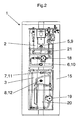
- the figures show a hot water tank 1 with four hydraulic connections 5, 6, 7, 8 at different height level, wherein the hydraulic connections 5, 6, 7, 8 penetrate a wall 4 of the hot water tank 1 on one side.
- the hot water tank 1 is enclosed by an insulation 15, wherein the insulation 15 at the location of the hydraulic connections 5, 6, 7, 8 has recesses.
- the hydraulic connections 5, 6, 7, 8 have on the outside of the hot water tank threaded. In this thread of the hydraulic connections 5, 6, 7, 8 engage four connecting pipes 9, 10, 11, 12 and thus penetrate the insulation 15th
- the rear walls 16, 17 of the hydraulic modules 2, 3 have openings, which surround the connection pipes 9, 10, 11, 12.
- On the side facing away from the hot water tank 1 side of the connecting pipes 9, 10, 11, 12 are external thread, which serve to fasten by means of appropriate nuts, the rear walls 16, 17 of the hydraulic modules 2, 3 on the hot water tank 1.
- the connecting pipes 9, 10, 11, 12 have on the memory-facing side within the thread via radially circumferential grooves 13, in each of which a radial seal 14 is arranged.
- the connecting pipes 9, 10, 11, 12 are first in the grooves 13 of the connecting pipes 9, 10, 11, 12 radial seals 14 inserted. Then the connecting pipes 9, 10, 11, 12 are inserted through the openings in the insulation 15 and screwed to the hydraulic connections 5, 6, 7, 8.
- the radial seals 14 seal off the transitions waterproof. Are the connecting pipes 9, 10, 11, 12 screwed, so they protrude beyond the insulation 15 of the hot water tank 1 addition.
- the connecting pipes 9, 10, 11, 12 have on the side facing away from the hot water tank 1 side over a larger diameter than on the hot water tank 1 associated side.
- the hydraulic modules 2, 3 are now placed such that the passages in the rear walls 16, 17 of the hydraulic modules 2, 3 are slipped over the connecting pipes 9, 10, 11, 12.
- connection pipes 9, 10, 11, 12 are connected to the pumps 18, 19 and the plate heat exchangers 20, 21 of the hydraulic modules 2, 3.
- the secondary side of the plate heat exchanger 20 of the hydraulic module 2 is connected to a solar collector, so that the hydraulic module 2 serves as a solar station.
- the secondary side of the plate heat exchanger 21 of the hydraulic module 3 is connected to service water pipes, so that the hydraulic module 3 serves as a fresh water station.
- the hydraulic threat can also be used as a fastener. This not only provides a simple way of mounting. Rather, a better insulation of the hot water tank 1 is achieved because, except the piping no further thermal bridges for fixing the hydraulic modules 2, 3 between hot water tank 1 and the environment penetrate the insulation 15.
Landscapes
- Engineering & Computer Science (AREA)
- Physics & Mathematics (AREA)
- Thermal Sciences (AREA)
- Chemical & Material Sciences (AREA)
- Combustion & Propulsion (AREA)
- Mechanical Engineering (AREA)
- General Engineering & Computer Science (AREA)
- Heat-Pump Type And Storage Water Heaters (AREA)
- Details Of Fluid Heaters (AREA)
- Domestic Hot-Water Supply Systems And Details Of Heating Systems (AREA)
- Housings, Intake/Discharge, And Installation Of Fluid Heaters (AREA)
Abstract
Description
- Die Erfindung bezieht sich auf einen Warmwasserspeicher in Verbindung mit mindestens einem an ihm montierten Hydraulikmodul zur thermischen Speicherbe- und -entladung
- Warmwasserspeicher dienen zur Bevorratung thermischer Energie. Zumeist wird in ihnen Heizungs- oder Brauchwasser bevorratet. Um dem Speicher thermische Energie zuzuführen, befindet sich häufig in dem Brauchwasserspeicher ein wendelförmiger Wärmetauscher, der von einem heizenden Medium durchströmt wird. Eine andere Möglichkeit besteht darin, dass dem Brauchwasserspeicher aus dem unteren Bereich kühles Wasser entzogen wird, welches in einem externen Wärmetauscher erwärmt und anschließend dem Speicher wieder zugeführt wird. Enthält der Warmwasserspeicher Heizungswasser, so muss die Wärme des Heizungswassers für die Brauchwasserbereitung in einem Wärmetauscher auf das Brauchwasser übertragen werden. Hierzu kann einerseits innerhalb des Warmwasserspeichers ein wendelförmiger Wärmetauscher angeordnet sein, welcher vom Brauchwasser durchströmt wird. Eine andere Möglichkeit besteht darin, warmes Heizungswasser aus dem Warmwasserspeicher abzuziehen und einen Teil dessen thermischer Energie in einem externen Plattenwärmetauscher auf das Brauchwasser zu übertragen.
- Häufig werden zum Be- und/oder Entladen eines Warmwasserspeichers Hydraulikmodule verwendet. Diese Hydraulikmodule stellen einen Baueinheit dar und enthalten außer einem Gehäuse zumindest eine Umwälzpumpe sowie einen Sekundärwärmetauscher, der zumeist als Plattenwärmetauscher ausgestaltet ist. Der Sekundärwärmetauscher ist mit zwei Anschlüssen mit dem Warmwasserspeicher verbunden, so dass Wasser abgezogen beziehungsweise zugeführt und somit Wärme in den Warmwasserspeicher eingebracht oder entzogen werden kann.
- Gemäß dem Stand der Technik werden Hydraulikmodule an der Außenseite eines Warmwasserspeichers mittels Schrauben befestigt, anschließend werden die hydraulischen Leitungen der Hydraulikmodule mit den Anschlüssen des Warmwasserspeichers verbunden.
- Der Erfindung liegt die Aufgabe zugrunde, die Aufhängung und Befestigung von Hydraulikmodulen an Warmwasserspeichern zu vereinfachen und die Wärmeverluste zu reduzieren.
- Erfindungsgemäß wird dies gemäß den Merkmalen des unabhängigen Anspruchs 1 dadurch gelöst, dass die hydraulischen Verbindungsleitungen zugleich als Befestigungselemente dienen.
- Vorteilhafte Ausgestaltungen der Erfindung ergeben sich durch die Merkmale der abhängigen Ansprüche.
- Die Erfindung wird nun anhand der Figuren detailliert erläutert. Hierbei zeigen:
-
Figur 1 einen Warmwasserspeicher mit zwei Hydraulikmodulen in der Seitenansicht (der Hydraulikmodule), -
Figur 2 denselben Warmwasserspeicher mit zwei Hydraulikmodulen in der Frontalansicht (der Hydraulikmodule) sowie -
Figur 3 die Verbindung des Warmwasserspeichers mit den einem Hydraulikmodul in einer Detailansicht. - Die Figuren zeigen einen Warmwasserspeicher 1 mit vier hydraulischen Anschlüssen 5, 6, 7, 8 auf unterschiedlichem Höhenniveau, wobei die hydraulischen Anschlüsse 5, 6, 7, 8 eine Wand 4 des Warmwasserspeichers 1 auf einer Seite durchdringen. Der Warmwasserspeicher 1 ist von einer Dämmung 15 umschlossen, wobei die Dämmung 15 an der Stelle der hydraulischen Anschlüsse 5, 6, 7, 8 Ausnehmungen aufweist. Die hydraulischen Anschlüsse 5, 6, 7, 8 verfügen auf der Außenseite des Warmwasserspeichers über Gewinde. In diese Gewinde der hydraulischen Anschlüsse 5, 6, 7, 8 greifen vier Anschlussrohre 9, 10, 11, 12 ein und durchdringen somit die Dämmung 15.
- Auf die Dämmung 15 des Warmwasserspeichers 1 sind zwei Hydraulikmodule 2, 3 aufgesetzt. Die Rückwände 16, 17 der Hydraulikmodule 2, 3 verfügen über Durchbrüche, welche die Anschlussrohre 9, 10, 11, 12 umschließen. Auf der dem Warmwasserspeichers 1 abgewandten Seite der Anschlussrohre 9, 10, 11, 12 befinden sich Außengewinde, welche dazu dienen, mittels entsprechender Muttern die Rückwände 16, 17 der Hydraulikmodule 2, 3 am Warmwasserspeicher 1 zu befestigen.
- Die Anschlussrohre 9, 10, 11, 12 verfügen auf der dem Speicher zugewandten Seite innerhalb der Gewinde über radial umlaufende Nuten 13, in welche jeweils eine Radialdichtung 14 angeordnet ist.
- Zur Montage der Hydraulikmodule 2, 3 werden zunächst in die Nuten 13 der Anschlussrohre 9, 10, 11, 12 Radialdichtungen 14 eingelegt. Dann werden die Anschlussrohre 9, 10, 11,12 durch die Öffnungen in der Dämmung 15 hindurch gesteckt und mit den hydraulischen Anschlüssen 5, 6, 7, 8 verschraubt. Die Radialdichtungen 14 dichten hierbei die Übergänge wasserdicht ab. Sind die Anschlussrohre 9, 10, 11, 12 verschraubt, so ragen diese über die Dämmung 15 des Warmwasserspeichers 1 hinaus. Die Anschlussrohre 9, 10, 11, 12 verfügen auf der dem Warmwasserspeicher 1 abgewandten Seite über einen größeren Durchmesser als auf der dem Warmwasserspeicher 1 zugeordneten Seite. Die Hydraulikmodule 2, 3 werden nun derart aufgesetzt, dass die Durchgänge in den Rückwänden 16, 17 der Hydraulikmodule 2, 3 über die Anschlussrohre 9, 10, 11, 12 gestülpt werden. Dadurch, dass die Rückwände 16, 17 auf dem größeren Durchmesser der Anschlussrohre 9, 10, 11, 12 aufliegen, wird die Flächenbelastung verringert. Anschließend werden Muttern 22 über die Außengewinde der Anschlussrohre 9, 10, 11, 12 geschraubt, so dass die Rückwände 16, 17 der Hydraulikmodule 2, 3 an den Warmwasserspeicher 1 gedrückt und mit ihm fest verbunden werden. Abschließend werden die Anschlussrohre 9, 10, 11, 12 mit den Pumpen 18, 19 und den Plattenwärmetauschern 20, 21 der Hydraulikmodule 2, 3 verbunden.
- Die Sekundärseite des Plattenwärmetauschers 20 des Hydraulikmoduls 2 wird mit einem Solarkollektor verbunden, so dass das Hydraulikmodul 2 als Solarstation dient. Die Sekundärseite des Plattenwärmetauschers 21 des Hydraulikmoduls 3 wird mit Brauchwasserleitungen verbunden, so dass das Hydraulikmodul 3 als Frischwasserstation dient.
- Somit kann die hydraulische Verrohung zugleich als Befestigungselement genutzt werden. Hierdurch besteht nicht nur eine einfache Möglichkeit der Montage. Vielmehr wird auch eine bessere Dämmung des Warmwasserspeichers 1 erreicht, da außer der Verrohrung keine weiteren Wärmebrücken zur Befestigung der Hydraulikmodule 2, 3 zwischen Warmwasserspeichers 1 und der Umgebung die Dämmung 15 durchdringen.
- Auf die verlängernden Anschlussrohre 9, 10, 11, 12 kann verzichtet werden, wenn die hydraulischen Anschlüsse 5, 6, 7, 8 über entsprechende Längen verfügen. Zur Abdichtung zwischen den hydraulischen Anschlüssen 5, 6, 7, 8 und den Anschlussrohren 9, 10, 11, 12 können auch andere Dichtmittel (z.B. Hanf oder Teflonband) verwendet werden.
- Anstelle von Gewinden können zur hydraulischen Verbindung auch Schnellkupplungen eingesetzt werden.
Claims (3)
- Warmwasserspeicher (1) mit mehreren die Wand (4) des Warmwasserspeicher (1) durchdringenden hydraulischen Anschlüssen (5, 6, 7, 8), welche auf der Außenseite des Warmwasserspeichers über Gewinde oder Schnellkupplungen verfügen,
zum Anschluss des oder der Hydraulikmodule (2, 3),
mindestens einem daran montiertem Hydraulikmodul (2, 3) zur thermischen Speicherbeladung und / oder Speicherentladung,
dadurch gekennzeichnet, dass vorzugsweise Anschlussrohre (9, 10, 11, 12) mit den hydraulischen Anschlüssen (5, 6, 7, 8) über Gewinde oder Schnellkupplungen verbindbar sind, wobei diese Anschlussrohre (9, 10, 11, 12) auf der den hydraulischen Anschlüssen (5, 6, 7, 8) gegenüberliegenden Seite ebenfalls über Gewinde oder Schnellkupplungen verfügen, jedes Hydraulikmodul (2, 3) über mindestens zwei Durchgänge in seiner Rückwand verfügt, die derartig angeordnet sind, dass die Rückwand des Hydraulikmoduls (2, 3) über mindestens zwei hydraulischen Anschlüssen (5, 6, 7, 8) oder Anschlussrohre (9, 10, 11, 12) gestülpt werden kann und mittels Muttern oder Schnellkupplungen an den hydraulischen Anschlüssen (5, 6, 7, 8) oder Anschlussrohre (9, 10, 11, 12) festgeschraubt werden kann. - Warmwasserspeicher (1) mit mindestens einem daran montiertem Hydraulikmodul (2, 3) zur thermischen Speicherbeladung und / oder Speicherentladung nach Anspruch 1,
dadurch gekennzeichnet, dass beim Vorhandensein von Anschlussrohren (9, 10, 11, 12) die Gewinde der Anschlussrohre (9, 10, 11, 12) oder der hydraulischen Anschlüsse (5, 6, 7, 8) jeweils von einer radialen Nut (13) unterbrochen sind und in dieser radialen Nut (13) eine Radialdichtung (14) angeordnet ist. - Warmwasserspeicher (1) mit mindestens einem daran montiertem Hydraulikmodul (2, 3) zur thermischen Speicherbeladung und / oder Speicherentladung nach Anspruch 1 oder 2, dadurch gekennzeichnet, dass beim Vorhandensein von Anschlussrohren (9, 10, 11, 12) diese auf der dem Warmwasserspeicher (1) zugeordneten Seite über einen kleineren Durchmesser verfügen als an der Stelle, an der sie die Rückwand des Hydraulikmoduls (2, 3) durchdringen.
Applications Claiming Priority (1)
| Application Number | Priority Date | Filing Date | Title |
|---|---|---|---|
| AT0035109A AT507979A3 (de) | 2009-03-04 | 2009-03-04 | Warmwasserspeicher |
Publications (3)
| Publication Number | Publication Date |
|---|---|
| EP2226589A2 true EP2226589A2 (de) | 2010-09-08 |
| EP2226589A3 EP2226589A3 (de) | 2015-09-16 |
| EP2226589B1 EP2226589B1 (de) | 2017-05-24 |
Family
ID=42154229
Family Applications (1)
| Application Number | Title | Priority Date | Filing Date |
|---|---|---|---|
| EP10001816.7A Not-in-force EP2226589B1 (de) | 2009-03-04 | 2010-02-23 | Warmwasserspeicher |
Country Status (5)
| Country | Link |
|---|---|
| EP (1) | EP2226589B1 (de) |
| AT (1) | AT507979A3 (de) |
| DK (1) | DK2226589T3 (de) |
| ES (1) | ES2631510T3 (de) |
| PL (1) | PL2226589T3 (de) |
Cited By (3)
| Publication number | Priority date | Publication date | Assignee | Title |
|---|---|---|---|---|
| NL2009663C2 (nl) * | 2012-10-18 | 2014-04-22 | Dijkstra | Verwarmingsinrichting en werkwijze voor het uitvoeren van onderhoud aan deze verwarmingsinrichting. |
| DE202014002655U1 (de) | 2014-03-27 | 2015-06-30 | Stiebel Eltron Gmbh & Co. Kg | Wärmeenergiesystem mit einem Wärmeerzeuger und einem Behälter |
| DE202015001751U1 (de) * | 2015-03-09 | 2016-06-10 | Stiebel Eltron Gmbh & Co. Kg | Umschaltbaugruppe und Warmwasserspeicher |
Families Citing this family (1)
| Publication number | Priority date | Publication date | Assignee | Title |
|---|---|---|---|---|
| WO2025228818A1 (en) * | 2024-04-30 | 2025-11-06 | Qvantum Industries Ab | A branching conduit module for a heat pump arrangement, a buffer tank assembly, and a heat pump arrangement |
Family Cites Families (7)
| Publication number | Priority date | Publication date | Assignee | Title |
|---|---|---|---|---|
| GB2241564B (en) * | 1990-03-01 | 1994-08-10 | Worcester Heat Systems Ltd | Improvements in or relating to water heating boilers |
| NL1002098C2 (nl) * | 1996-01-15 | 1997-07-16 | Radson Alutherm Nv | Verwarmingstoestel. |
| DE10057943B4 (de) * | 2000-11-22 | 2007-10-11 | Wolf Gmbh | Gastherme oder Gasbrennwerttherme |
| DE20217242U1 (de) * | 2002-11-08 | 2003-03-27 | Moser, Peter, 07749 Jena | Universeller Armaturenbaukasten für Wasserspeicher mit anpassbarem Gehäuse |
| DE10304679A1 (de) * | 2003-02-05 | 2004-08-26 | Wolf Gmbh | Heiz-und Brauchwasseranlage |
| DE10326262B4 (de) * | 2003-06-11 | 2005-10-20 | Bosch Gmbh Robert | Wärmeerzeuger für Heizzwecke und Warmwasserbereitung |
| DE102004019720A1 (de) * | 2004-04-20 | 2005-11-10 | Spaun, Heinrich, von | Warmwasserheizungsanlage für Gebäude |
-
2009
- 2009-03-04 AT AT0035109A patent/AT507979A3/de not_active Application Discontinuation
-
2010
- 2010-02-23 PL PL10001816T patent/PL2226589T3/pl unknown
- 2010-02-23 ES ES10001816.7T patent/ES2631510T3/es active Active
- 2010-02-23 DK DK10001816.7T patent/DK2226589T3/en active
- 2010-02-23 EP EP10001816.7A patent/EP2226589B1/de not_active Not-in-force
Non-Patent Citations (1)
| Title |
|---|
| None |
Cited By (3)
| Publication number | Priority date | Publication date | Assignee | Title |
|---|---|---|---|---|
| NL2009663C2 (nl) * | 2012-10-18 | 2014-04-22 | Dijkstra | Verwarmingsinrichting en werkwijze voor het uitvoeren van onderhoud aan deze verwarmingsinrichting. |
| DE202014002655U1 (de) | 2014-03-27 | 2015-06-30 | Stiebel Eltron Gmbh & Co. Kg | Wärmeenergiesystem mit einem Wärmeerzeuger und einem Behälter |
| DE202015001751U1 (de) * | 2015-03-09 | 2016-06-10 | Stiebel Eltron Gmbh & Co. Kg | Umschaltbaugruppe und Warmwasserspeicher |
Also Published As
| Publication number | Publication date |
|---|---|
| PL2226589T3 (pl) | 2017-09-29 |
| ES2631510T3 (es) | 2017-08-31 |
| EP2226589B1 (de) | 2017-05-24 |
| AT507979A3 (de) | 2011-11-15 |
| DK2226589T3 (en) | 2017-07-24 |
| EP2226589A3 (de) | 2015-09-16 |
| AT507979A2 (de) | 2010-09-15 |
Similar Documents
| Publication | Publication Date | Title |
|---|---|---|
| DE102006058629B3 (de) | Kühlanordnung für einen Kondensator | |
| EP2226589B1 (de) | Warmwasserspeicher | |
| CH711262A1 (de) | Kühlelement zum Aufrüsten eines Photovoltaikmoduls und Verfahren zum Aufrüsten eines solchen. | |
| EP0099875A2 (de) | Vorrichtung zur Erwärmung von Heizungswasser und von Brauchwasser | |
| DE2933088C2 (de) | Temperaturstabilisierung für ein wärmeabgebendes Bauteil eines Satelliten | |
| DE202022103006U1 (de) | Wärmesenke für elektrische Ausrüstung in Kraftwerken | |
| WO2008043389A1 (de) | Transformator für meeresströmungskraftwerk | |
| DE102008011960A1 (de) | Latentwärmespeicherzelle und Wärmespeichervorrichtung | |
| EP2128532A2 (de) | Solarthermische Anlage mit einem Kreislauf für ein Wärmeträgermedium | |
| EP2295889A2 (de) | Kondensationsspeicher in einem Wärmepumpenkreislauf | |
| DE2920577A1 (de) | Verfahren zum einbau von waermerohren, waermerohr dafuer und aus solchen waermerohren aufgebauter waermetauscher | |
| DE102012018577A1 (de) | Temperiereinrichtung | |
| DE202007015474U1 (de) | Erdgedeckter externer Wärmespeicher | |
| DE10306148B3 (de) | Wärmetauscher-Vorrichtung für den Kältekreislauf einer Wärmepumpe | |
| DE3934084A1 (de) | Fluessigkeitskuehleinrichtung fuer eine hochtemperaturspeicherbatterie | |
| DE102007062342B4 (de) | Verfahren und Anordnung zur Erhöhung des Temperaturniveaus im Kreislauf solarthermischer Anlagen oder Blockheizkraftwerke | |
| DE102022206472A1 (de) | Kühlmittelsammeleinrichtung | |
| DE102010031226A1 (de) | Transporteinrichtung und Substratbehandlungsanlage | |
| AT518437B1 (de) | Verfahren und Vorrichtung zur Speicherung von Wärme | |
| DE102022004521A1 (de) | Technik zum Wärmetauschen | |
| EP0611923B1 (de) | Verfahren zur Bekämpfung von Legionellen in einer Warmwasserspeicheranlage | |
| EP4573617B1 (de) | Kühlmittelsammeleinrichtung mit starren rohrverbindungen | |
| DE19934412C1 (de) | Speisewasser-Pumpanordnung für ein Kraftwerk, insbesondere für eine GUD-Anlage | |
| DE102010015851A1 (de) | Solarheizung | |
| EP3645698B1 (de) | System zur kühlung eines brauverfahrens |
Legal Events
| Date | Code | Title | Description |
|---|---|---|---|
| PUAI | Public reference made under article 153(3) epc to a published international application that has entered the european phase |
Free format text: ORIGINAL CODE: 0009012 |
|
| AK | Designated contracting states |
Kind code of ref document: A2 Designated state(s): AT BE BG CH CY CZ DE DK EE ES FI FR GB GR HR HU IE IS IT LI LT LU LV MC MK MT NL NO PL PT RO SE SI SK SM TR |
|
| AX | Request for extension of the european patent |
Extension state: AL BA RS |
|
| PUAL | Search report despatched |
Free format text: ORIGINAL CODE: 0009013 |
|
| AK | Designated contracting states |
Kind code of ref document: A3 Designated state(s): AT BE BG CH CY CZ DE DK EE ES FI FR GB GR HR HU IE IS IT LI LT LU LV MC MK MT NL NO PL PT RO SE SI SK SM TR |
|
| AX | Request for extension of the european patent |
Extension state: AL BA RS |
|
| RIC1 | Information provided on ipc code assigned before grant |
Ipc: F24H 9/06 20060101AFI20150813BHEP Ipc: F24H 9/12 20060101ALI20150813BHEP Ipc: F24H 9/14 20060101ALI20150813BHEP |
|
| 17P | Request for examination filed |
Effective date: 20160310 |
|
| RBV | Designated contracting states (corrected) |
Designated state(s): AT BE BG CH CY CZ DE DK EE ES FI FR GB GR HR HU IE IS IT LI LT LU LV MC MK MT NL NO PL PT RO SE SI SK SM TR |
|
| GRAP | Despatch of communication of intention to grant a patent |
Free format text: ORIGINAL CODE: EPIDOSNIGR1 |
|
| INTG | Intention to grant announced |
Effective date: 20170102 |
|
| GRAS | Grant fee paid |
Free format text: ORIGINAL CODE: EPIDOSNIGR3 |
|
| GRAA | (expected) grant |
Free format text: ORIGINAL CODE: 0009210 |
|
| AK | Designated contracting states |
Kind code of ref document: B1 Designated state(s): AT BE BG CH CY CZ DE DK EE ES FI FR GB GR HR HU IE IS IT LI LT LU LV MC MK MT NL NO PL PT RO SE SI SK SM TR |
|
| REG | Reference to a national code |
Ref country code: GB Ref legal event code: FG4D Free format text: NOT ENGLISH |
|
| REG | Reference to a national code |
Ref country code: CH Ref legal event code: EP |
|
| REG | Reference to a national code |
Ref country code: IE Ref legal event code: FG4D Free format text: LANGUAGE OF EP DOCUMENT: GERMAN |
|
| REG | Reference to a national code |
Ref country code: AT Ref legal event code: REF Ref document number: 896214 Country of ref document: AT Kind code of ref document: T Effective date: 20170615 |
|
| REG | Reference to a national code |
Ref country code: DE Ref legal event code: R096 Ref document number: 502010013637 Country of ref document: DE |
|
| REG | Reference to a national code |
Ref country code: NL Ref legal event code: FP |
|
| REG | Reference to a national code |
Ref country code: DK Ref legal event code: T3 Effective date: 20170714 |
|
| REG | Reference to a national code |
Ref country code: ES Ref legal event code: FG2A Ref document number: 2631510 Country of ref document: ES Kind code of ref document: T3 Effective date: 20170831 |
|
| REG | Reference to a national code |
Ref country code: LT Ref legal event code: MG4D |
|
| PG25 | Lapsed in a contracting state [announced via postgrant information from national office to epo] |
Ref country code: LT Free format text: LAPSE BECAUSE OF FAILURE TO SUBMIT A TRANSLATION OF THE DESCRIPTION OR TO PAY THE FEE WITHIN THE PRESCRIBED TIME-LIMIT Effective date: 20170524 Ref country code: NO Free format text: LAPSE BECAUSE OF FAILURE TO SUBMIT A TRANSLATION OF THE DESCRIPTION OR TO PAY THE FEE WITHIN THE PRESCRIBED TIME-LIMIT Effective date: 20170824 Ref country code: FI Free format text: LAPSE BECAUSE OF FAILURE TO SUBMIT A TRANSLATION OF THE DESCRIPTION OR TO PAY THE FEE WITHIN THE PRESCRIBED TIME-LIMIT Effective date: 20170524 Ref country code: GR Free format text: LAPSE BECAUSE OF FAILURE TO SUBMIT A TRANSLATION OF THE DESCRIPTION OR TO PAY THE FEE WITHIN THE PRESCRIBED TIME-LIMIT Effective date: 20170825 Ref country code: HR Free format text: LAPSE BECAUSE OF FAILURE TO SUBMIT A TRANSLATION OF THE DESCRIPTION OR TO PAY THE FEE WITHIN THE PRESCRIBED TIME-LIMIT Effective date: 20170524 |
|
| PG25 | Lapsed in a contracting state [announced via postgrant information from national office to epo] |
Ref country code: LV Free format text: LAPSE BECAUSE OF FAILURE TO SUBMIT A TRANSLATION OF THE DESCRIPTION OR TO PAY THE FEE WITHIN THE PRESCRIBED TIME-LIMIT Effective date: 20170524 Ref country code: IS Free format text: LAPSE BECAUSE OF FAILURE TO SUBMIT A TRANSLATION OF THE DESCRIPTION OR TO PAY THE FEE WITHIN THE PRESCRIBED TIME-LIMIT Effective date: 20170924 Ref country code: BG Free format text: LAPSE BECAUSE OF FAILURE TO SUBMIT A TRANSLATION OF THE DESCRIPTION OR TO PAY THE FEE WITHIN THE PRESCRIBED TIME-LIMIT Effective date: 20170824 Ref country code: SE Free format text: LAPSE BECAUSE OF FAILURE TO SUBMIT A TRANSLATION OF THE DESCRIPTION OR TO PAY THE FEE WITHIN THE PRESCRIBED TIME-LIMIT Effective date: 20170524 |
|
| PG25 | Lapsed in a contracting state [announced via postgrant information from national office to epo] |
Ref country code: EE Free format text: LAPSE BECAUSE OF FAILURE TO SUBMIT A TRANSLATION OF THE DESCRIPTION OR TO PAY THE FEE WITHIN THE PRESCRIBED TIME-LIMIT Effective date: 20170524 Ref country code: RO Free format text: LAPSE BECAUSE OF FAILURE TO SUBMIT A TRANSLATION OF THE DESCRIPTION OR TO PAY THE FEE WITHIN THE PRESCRIBED TIME-LIMIT Effective date: 20170524 Ref country code: CZ Free format text: LAPSE BECAUSE OF FAILURE TO SUBMIT A TRANSLATION OF THE DESCRIPTION OR TO PAY THE FEE WITHIN THE PRESCRIBED TIME-LIMIT Effective date: 20170524 Ref country code: SK Free format text: LAPSE BECAUSE OF FAILURE TO SUBMIT A TRANSLATION OF THE DESCRIPTION OR TO PAY THE FEE WITHIN THE PRESCRIBED TIME-LIMIT Effective date: 20170524 |
|
| REG | Reference to a national code |
Ref country code: DE Ref legal event code: R097 Ref document number: 502010013637 Country of ref document: DE |
|
| PG25 | Lapsed in a contracting state [announced via postgrant information from national office to epo] |
Ref country code: SM Free format text: LAPSE BECAUSE OF FAILURE TO SUBMIT A TRANSLATION OF THE DESCRIPTION OR TO PAY THE FEE WITHIN THE PRESCRIBED TIME-LIMIT Effective date: 20170524 |
|
| PLBE | No opposition filed within time limit |
Free format text: ORIGINAL CODE: 0009261 |
|
| STAA | Information on the status of an ep patent application or granted ep patent |
Free format text: STATUS: NO OPPOSITION FILED WITHIN TIME LIMIT |
|
| 26N | No opposition filed |
Effective date: 20180227 |
|
| PG25 | Lapsed in a contracting state [announced via postgrant information from national office to epo] |
Ref country code: SI Free format text: LAPSE BECAUSE OF FAILURE TO SUBMIT A TRANSLATION OF THE DESCRIPTION OR TO PAY THE FEE WITHIN THE PRESCRIBED TIME-LIMIT Effective date: 20170524 |
|
| REG | Reference to a national code |
Ref country code: CH Ref legal event code: PL |
|
| PG25 | Lapsed in a contracting state [announced via postgrant information from national office to epo] |
Ref country code: MT Free format text: LAPSE BECAUSE OF FAILURE TO SUBMIT A TRANSLATION OF THE DESCRIPTION OR TO PAY THE FEE WITHIN THE PRESCRIBED TIME-LIMIT Effective date: 20170524 Ref country code: MC Free format text: LAPSE BECAUSE OF FAILURE TO SUBMIT A TRANSLATION OF THE DESCRIPTION OR TO PAY THE FEE WITHIN THE PRESCRIBED TIME-LIMIT Effective date: 20170524 |
|
| REG | Reference to a national code |
Ref country code: IE Ref legal event code: MM4A |
|
| PG25 | Lapsed in a contracting state [announced via postgrant information from national office to epo] |
Ref country code: LU Free format text: LAPSE BECAUSE OF NON-PAYMENT OF DUE FEES Effective date: 20180223 Ref country code: LI Free format text: LAPSE BECAUSE OF NON-PAYMENT OF DUE FEES Effective date: 20180228 Ref country code: CH Free format text: LAPSE BECAUSE OF NON-PAYMENT OF DUE FEES Effective date: 20180228 |
|
| REG | Reference to a national code |
Ref country code: FR Ref legal event code: ST Effective date: 20181031 |
|
| PG25 | Lapsed in a contracting state [announced via postgrant information from national office to epo] |
Ref country code: IE Free format text: LAPSE BECAUSE OF NON-PAYMENT OF DUE FEES Effective date: 20180223 |
|
| PG25 | Lapsed in a contracting state [announced via postgrant information from national office to epo] |
Ref country code: FR Free format text: LAPSE BECAUSE OF NON-PAYMENT OF DUE FEES Effective date: 20180228 |
|
| PG25 | Lapsed in a contracting state [announced via postgrant information from national office to epo] |
Ref country code: TR Free format text: LAPSE BECAUSE OF FAILURE TO SUBMIT A TRANSLATION OF THE DESCRIPTION OR TO PAY THE FEE WITHIN THE PRESCRIBED TIME-LIMIT Effective date: 20170524 |
|
| PG25 | Lapsed in a contracting state [announced via postgrant information from national office to epo] |
Ref country code: PT Free format text: LAPSE BECAUSE OF FAILURE TO SUBMIT A TRANSLATION OF THE DESCRIPTION OR TO PAY THE FEE WITHIN THE PRESCRIBED TIME-LIMIT Effective date: 20170524 Ref country code: HU Free format text: LAPSE BECAUSE OF FAILURE TO SUBMIT A TRANSLATION OF THE DESCRIPTION OR TO PAY THE FEE WITHIN THE PRESCRIBED TIME-LIMIT; INVALID AB INITIO Effective date: 20100223 |
|
| PG25 | Lapsed in a contracting state [announced via postgrant information from national office to epo] |
Ref country code: CY Free format text: LAPSE BECAUSE OF FAILURE TO SUBMIT A TRANSLATION OF THE DESCRIPTION OR TO PAY THE FEE WITHIN THE PRESCRIBED TIME-LIMIT Effective date: 20170524 Ref country code: MK Free format text: LAPSE BECAUSE OF NON-PAYMENT OF DUE FEES Effective date: 20170524 |
|
| PGFP | Annual fee paid to national office [announced via postgrant information from national office to epo] |
Ref country code: GB Payment date: 20220121 Year of fee payment: 13 Ref country code: DK Payment date: 20220202 Year of fee payment: 13 Ref country code: DE Payment date: 20220126 Year of fee payment: 13 Ref country code: AT Payment date: 20220131 Year of fee payment: 13 |
|
| PGFP | Annual fee paid to national office [announced via postgrant information from national office to epo] |
Ref country code: PL Payment date: 20220201 Year of fee payment: 13 Ref country code: NL Payment date: 20220126 Year of fee payment: 13 Ref country code: IT Payment date: 20220228 Year of fee payment: 13 Ref country code: ES Payment date: 20220301 Year of fee payment: 13 Ref country code: BE Payment date: 20220126 Year of fee payment: 13 |
|
| REG | Reference to a national code |
Ref country code: DE Ref legal event code: R119 Ref document number: 502010013637 Country of ref document: DE |
|
| REG | Reference to a national code |
Ref country code: DK Ref legal event code: EBP Effective date: 20230228 |
|
| REG | Reference to a national code |
Ref country code: NL Ref legal event code: MM Effective date: 20230301 |
|
| REG | Reference to a national code |
Ref country code: AT Ref legal event code: MM01 Ref document number: 896214 Country of ref document: AT Kind code of ref document: T Effective date: 20230223 |
|
| REG | Reference to a national code |
Ref country code: BE Ref legal event code: MM Effective date: 20230228 |
|
| GBPC | Gb: european patent ceased through non-payment of renewal fee |
Effective date: 20230223 |
|
| PG25 | Lapsed in a contracting state [announced via postgrant information from national office to epo] |
Ref country code: AT Free format text: LAPSE BECAUSE OF NON-PAYMENT OF DUE FEES Effective date: 20230223 |
|
| PG25 | Lapsed in a contracting state [announced via postgrant information from national office to epo] |
Ref country code: NL Free format text: LAPSE BECAUSE OF NON-PAYMENT OF DUE FEES Effective date: 20230301 |
|
| PG25 | Lapsed in a contracting state [announced via postgrant information from national office to epo] |
Ref country code: GB Free format text: LAPSE BECAUSE OF NON-PAYMENT OF DUE FEES Effective date: 20230223 |
|
| PG25 | Lapsed in a contracting state [announced via postgrant information from national office to epo] |
Ref country code: IT Free format text: LAPSE BECAUSE OF NON-PAYMENT OF DUE FEES Effective date: 20230223 Ref country code: GB Free format text: LAPSE BECAUSE OF NON-PAYMENT OF DUE FEES Effective date: 20230223 Ref country code: DK Free format text: LAPSE BECAUSE OF NON-PAYMENT OF DUE FEES Effective date: 20230228 Ref country code: DE Free format text: LAPSE BECAUSE OF NON-PAYMENT OF DUE FEES Effective date: 20230901 |
|
| PG25 | Lapsed in a contracting state [announced via postgrant information from national office to epo] |
Ref country code: BE Free format text: LAPSE BECAUSE OF NON-PAYMENT OF DUE FEES Effective date: 20230228 |
|
| REG | Reference to a national code |
Ref country code: ES Ref legal event code: FD2A Effective date: 20240405 |
|
| PG25 | Lapsed in a contracting state [announced via postgrant information from national office to epo] |
Ref country code: ES Free format text: LAPSE BECAUSE OF NON-PAYMENT OF DUE FEES Effective date: 20230224 |
|
| PG25 | Lapsed in a contracting state [announced via postgrant information from national office to epo] |
Ref country code: ES Free format text: LAPSE BECAUSE OF NON-PAYMENT OF DUE FEES Effective date: 20230224 |
|
| PG25 | Lapsed in a contracting state [announced via postgrant information from national office to epo] |
Ref country code: PL Free format text: LAPSE BECAUSE OF NON-PAYMENT OF DUE FEES Effective date: 20230223 |
|
| PG25 | Lapsed in a contracting state [announced via postgrant information from national office to epo] |
Ref country code: PL Free format text: LAPSE BECAUSE OF NON-PAYMENT OF DUE FEES Effective date: 20230223 |