EP2225501B2 - Kryogenes kühlverfahren und entsprechende vorrichtung - Google Patents
Kryogenes kühlverfahren und entsprechende vorrichtung Download PDFInfo
- Publication number
- EP2225501B2 EP2225501B2 EP08852903.7A EP08852903A EP2225501B2 EP 2225501 B2 EP2225501 B2 EP 2225501B2 EP 08852903 A EP08852903 A EP 08852903A EP 2225501 B2 EP2225501 B2 EP 2225501B2
- Authority
- EP
- European Patent Office
- Prior art keywords
- fluid
- expansion
- compressors
- working
- section
- Prior art date
- Legal status (The legal status is an assumption and is not a legal conclusion. Google has not performed a legal analysis and makes no representation as to the accuracy of the status listed.)
- Active
Links
Images
Classifications
-
- F—MECHANICAL ENGINEERING; LIGHTING; HEATING; WEAPONS; BLASTING
- F25—REFRIGERATION OR COOLING; COMBINED HEATING AND REFRIGERATION SYSTEMS; HEAT PUMP SYSTEMS; MANUFACTURE OR STORAGE OF ICE; LIQUEFACTION SOLIDIFICATION OF GASES
- F25B—REFRIGERATION MACHINES, PLANTS OR SYSTEMS; COMBINED HEATING AND REFRIGERATION SYSTEMS; HEAT PUMP SYSTEMS
- F25B9/00—Compression machines, plants or systems, in which the refrigerant is air or other gas of low boiling point
- F25B9/14—Compression machines, plants or systems, in which the refrigerant is air or other gas of low boiling point characterised by the cycle used, e.g. Stirling cycle
-
- F—MECHANICAL ENGINEERING; LIGHTING; HEATING; WEAPONS; BLASTING
- F25—REFRIGERATION OR COOLING; COMBINED HEATING AND REFRIGERATION SYSTEMS; HEAT PUMP SYSTEMS; MANUFACTURE OR STORAGE OF ICE; LIQUEFACTION SOLIDIFICATION OF GASES
- F25B—REFRIGERATION MACHINES, PLANTS OR SYSTEMS; COMBINED HEATING AND REFRIGERATION SYSTEMS; HEAT PUMP SYSTEMS
- F25B1/00—Compression machines, plants or systems with non-reversible cycle
- F25B1/10—Compression machines, plants or systems with non-reversible cycle with multi-stage compression
-
- F—MECHANICAL ENGINEERING; LIGHTING; HEATING; WEAPONS; BLASTING
- F25—REFRIGERATION OR COOLING; COMBINED HEATING AND REFRIGERATION SYSTEMS; HEAT PUMP SYSTEMS; MANUFACTURE OR STORAGE OF ICE; LIQUEFACTION SOLIDIFICATION OF GASES
- F25B—REFRIGERATION MACHINES, PLANTS OR SYSTEMS; COMBINED HEATING AND REFRIGERATION SYSTEMS; HEAT PUMP SYSTEMS
- F25B9/00—Compression machines, plants or systems, in which the refrigerant is air or other gas of low boiling point
- F25B9/06—Compression machines, plants or systems, in which the refrigerant is air or other gas of low boiling point using expanders
-
- F—MECHANICAL ENGINEERING; LIGHTING; HEATING; WEAPONS; BLASTING
- F25—REFRIGERATION OR COOLING; COMBINED HEATING AND REFRIGERATION SYSTEMS; HEAT PUMP SYSTEMS; MANUFACTURE OR STORAGE OF ICE; LIQUEFACTION SOLIDIFICATION OF GASES
- F25B—REFRIGERATION MACHINES, PLANTS OR SYSTEMS; COMBINED HEATING AND REFRIGERATION SYSTEMS; HEAT PUMP SYSTEMS
- F25B9/00—Compression machines, plants or systems, in which the refrigerant is air or other gas of low boiling point
- F25B9/10—Compression machines, plants or systems, in which the refrigerant is air or other gas of low boiling point with several cooling stages
-
- F—MECHANICAL ENGINEERING; LIGHTING; HEATING; WEAPONS; BLASTING
- F25—REFRIGERATION OR COOLING; COMBINED HEATING AND REFRIGERATION SYSTEMS; HEAT PUMP SYSTEMS; MANUFACTURE OR STORAGE OF ICE; LIQUEFACTION SOLIDIFICATION OF GASES
- F25J—LIQUEFACTION, SOLIDIFICATION OR SEPARATION OF GASES OR GASEOUS OR LIQUEFIED GASEOUS MIXTURES BY PRESSURE AND COLD TREATMENT OR BY BRINGING THEM INTO THE SUPERCRITICAL STATE
- F25J1/00—Processes or apparatus for liquefying or solidifying gases or gaseous mixtures
- F25J1/003—Processes or apparatus for liquefying or solidifying gases or gaseous mixtures characterised by the kind of cold generation within the liquefaction unit for compensating heat leaks and liquid production
- F25J1/0047—Processes or apparatus for liquefying or solidifying gases or gaseous mixtures characterised by the kind of cold generation within the liquefaction unit for compensating heat leaks and liquid production using an "external" refrigerant stream in a closed vapor compression cycle
- F25J1/005—Processes or apparatus for liquefying or solidifying gases or gaseous mixtures characterised by the kind of cold generation within the liquefaction unit for compensating heat leaks and liquid production using an "external" refrigerant stream in a closed vapor compression cycle by expansion of a gaseous refrigerant stream with extraction of work
-
- F—MECHANICAL ENGINEERING; LIGHTING; HEATING; WEAPONS; BLASTING
- F25—REFRIGERATION OR COOLING; COMBINED HEATING AND REFRIGERATION SYSTEMS; HEAT PUMP SYSTEMS; MANUFACTURE OR STORAGE OF ICE; LIQUEFACTION SOLIDIFICATION OF GASES
- F25J—LIQUEFACTION, SOLIDIFICATION OR SEPARATION OF GASES OR GASEOUS OR LIQUEFIED GASEOUS MIXTURES BY PRESSURE AND COLD TREATMENT OR BY BRINGING THEM INTO THE SUPERCRITICAL STATE
- F25J1/00—Processes or apparatus for liquefying or solidifying gases or gaseous mixtures
- F25J1/006—Processes or apparatus for liquefying or solidifying gases or gaseous mixtures characterised by the refrigerant fluid used
- F25J1/0062—Light or noble gases, mixtures thereof
- F25J1/0065—Helium
-
- F—MECHANICAL ENGINEERING; LIGHTING; HEATING; WEAPONS; BLASTING
- F25—REFRIGERATION OR COOLING; COMBINED HEATING AND REFRIGERATION SYSTEMS; HEAT PUMP SYSTEMS; MANUFACTURE OR STORAGE OF ICE; LIQUEFACTION SOLIDIFICATION OF GASES
- F25J—LIQUEFACTION, SOLIDIFICATION OR SEPARATION OF GASES OR GASEOUS OR LIQUEFIED GASEOUS MIXTURES BY PRESSURE AND COLD TREATMENT OR BY BRINGING THEM INTO THE SUPERCRITICAL STATE
- F25J1/00—Processes or apparatus for liquefying or solidifying gases or gaseous mixtures
- F25J1/006—Processes or apparatus for liquefying or solidifying gases or gaseous mixtures characterised by the refrigerant fluid used
- F25J1/007—Primary atmospheric gases, mixtures thereof
- F25J1/0072—Nitrogen
-
- F—MECHANICAL ENGINEERING; LIGHTING; HEATING; WEAPONS; BLASTING
- F25—REFRIGERATION OR COOLING; COMBINED HEATING AND REFRIGERATION SYSTEMS; HEAT PUMP SYSTEMS; MANUFACTURE OR STORAGE OF ICE; LIQUEFACTION SOLIDIFICATION OF GASES
- F25J—LIQUEFACTION, SOLIDIFICATION OR SEPARATION OF GASES OR GASEOUS OR LIQUEFIED GASEOUS MIXTURES BY PRESSURE AND COLD TREATMENT OR BY BRINGING THEM INTO THE SUPERCRITICAL STATE
- F25J1/00—Processes or apparatus for liquefying or solidifying gases or gaseous mixtures
- F25J1/006—Processes or apparatus for liquefying or solidifying gases or gaseous mixtures characterised by the refrigerant fluid used
- F25J1/007—Primary atmospheric gases, mixtures thereof
- F25J1/0075—Oxygen
-
- F—MECHANICAL ENGINEERING; LIGHTING; HEATING; WEAPONS; BLASTING
- F25—REFRIGERATION OR COOLING; COMBINED HEATING AND REFRIGERATION SYSTEMS; HEAT PUMP SYSTEMS; MANUFACTURE OR STORAGE OF ICE; LIQUEFACTION SOLIDIFICATION OF GASES
- F25J—LIQUEFACTION, SOLIDIFICATION OR SEPARATION OF GASES OR GASEOUS OR LIQUEFIED GASEOUS MIXTURES BY PRESSURE AND COLD TREATMENT OR BY BRINGING THEM INTO THE SUPERCRITICAL STATE
- F25J1/00—Processes or apparatus for liquefying or solidifying gases or gaseous mixtures
- F25J1/006—Processes or apparatus for liquefying or solidifying gases or gaseous mixtures characterised by the refrigerant fluid used
- F25J1/007—Primary atmospheric gases, mixtures thereof
- F25J1/0077—Argon
-
- F—MECHANICAL ENGINEERING; LIGHTING; HEATING; WEAPONS; BLASTING
- F25—REFRIGERATION OR COOLING; COMBINED HEATING AND REFRIGERATION SYSTEMS; HEAT PUMP SYSTEMS; MANUFACTURE OR STORAGE OF ICE; LIQUEFACTION SOLIDIFICATION OF GASES
- F25J—LIQUEFACTION, SOLIDIFICATION OR SEPARATION OF GASES OR GASEOUS OR LIQUEFIED GASEOUS MIXTURES BY PRESSURE AND COLD TREATMENT OR BY BRINGING THEM INTO THE SUPERCRITICAL STATE
- F25J1/00—Processes or apparatus for liquefying or solidifying gases or gaseous mixtures
- F25J1/006—Processes or apparatus for liquefying or solidifying gases or gaseous mixtures characterised by the refrigerant fluid used
- F25J1/008—Hydrocarbons
- F25J1/0082—Methane
-
- F—MECHANICAL ENGINEERING; LIGHTING; HEATING; WEAPONS; BLASTING
- F25—REFRIGERATION OR COOLING; COMBINED HEATING AND REFRIGERATION SYSTEMS; HEAT PUMP SYSTEMS; MANUFACTURE OR STORAGE OF ICE; LIQUEFACTION SOLIDIFICATION OF GASES
- F25J—LIQUEFACTION, SOLIDIFICATION OR SEPARATION OF GASES OR GASEOUS OR LIQUEFIED GASEOUS MIXTURES BY PRESSURE AND COLD TREATMENT OR BY BRINGING THEM INTO THE SUPERCRITICAL STATE
- F25J1/00—Processes or apparatus for liquefying or solidifying gases or gaseous mixtures
- F25J1/006—Processes or apparatus for liquefying or solidifying gases or gaseous mixtures characterised by the refrigerant fluid used
- F25J1/0095—Oxides of carbon, e.g. CO2
-
- F—MECHANICAL ENGINEERING; LIGHTING; HEATING; WEAPONS; BLASTING
- F25—REFRIGERATION OR COOLING; COMBINED HEATING AND REFRIGERATION SYSTEMS; HEAT PUMP SYSTEMS; MANUFACTURE OR STORAGE OF ICE; LIQUEFACTION SOLIDIFICATION OF GASES
- F25J—LIQUEFACTION, SOLIDIFICATION OR SEPARATION OF GASES OR GASEOUS OR LIQUEFIED GASEOUS MIXTURES BY PRESSURE AND COLD TREATMENT OR BY BRINGING THEM INTO THE SUPERCRITICAL STATE
- F25J1/00—Processes or apparatus for liquefying or solidifying gases or gaseous mixtures
- F25J1/006—Processes or apparatus for liquefying or solidifying gases or gaseous mixtures characterised by the refrigerant fluid used
- F25J1/0097—Others, e.g. F-, Cl-, HF-, HClF-, HCl-hydrocarbons etc. or mixtures thereof
-
- F—MECHANICAL ENGINEERING; LIGHTING; HEATING; WEAPONS; BLASTING
- F25—REFRIGERATION OR COOLING; COMBINED HEATING AND REFRIGERATION SYSTEMS; HEAT PUMP SYSTEMS; MANUFACTURE OR STORAGE OF ICE; LIQUEFACTION SOLIDIFICATION OF GASES
- F25J—LIQUEFACTION, SOLIDIFICATION OR SEPARATION OF GASES OR GASEOUS OR LIQUEFIED GASEOUS MIXTURES BY PRESSURE AND COLD TREATMENT OR BY BRINGING THEM INTO THE SUPERCRITICAL STATE
- F25J1/00—Processes or apparatus for liquefying or solidifying gases or gaseous mixtures
- F25J1/02—Processes or apparatus for liquefying or solidifying gases or gaseous mixtures requiring the use of refrigeration, e.g. of helium or hydrogen ; Details and kind of the refrigeration system used; Integration with other units or processes; Controlling aspects of the process
- F25J1/0243—Start-up or control of the process; Details of the apparatus used; Details of the refrigerant compression system used
- F25J1/0257—Construction and layout of liquefaction equipments, e.g. valves, machines
- F25J1/0275—Construction and layout of liquefaction equipments, e.g. valves, machines adapted for special use of the liquefaction unit, e.g. portable or transportable devices
- F25J1/0276—Laboratory or other miniature devices
-
- F—MECHANICAL ENGINEERING; LIGHTING; HEATING; WEAPONS; BLASTING
- F25—REFRIGERATION OR COOLING; COMBINED HEATING AND REFRIGERATION SYSTEMS; HEAT PUMP SYSTEMS; MANUFACTURE OR STORAGE OF ICE; LIQUEFACTION SOLIDIFICATION OF GASES
- F25J—LIQUEFACTION, SOLIDIFICATION OR SEPARATION OF GASES OR GASEOUS OR LIQUEFIED GASEOUS MIXTURES BY PRESSURE AND COLD TREATMENT OR BY BRINGING THEM INTO THE SUPERCRITICAL STATE
- F25J1/00—Processes or apparatus for liquefying or solidifying gases or gaseous mixtures
- F25J1/02—Processes or apparatus for liquefying or solidifying gases or gaseous mixtures requiring the use of refrigeration, e.g. of helium or hydrogen ; Details and kind of the refrigeration system used; Integration with other units or processes; Controlling aspects of the process
- F25J1/0243—Start-up or control of the process; Details of the apparatus used; Details of the refrigerant compression system used
- F25J1/0279—Compression of refrigerant or internal recycle fluid, e.g. kind of compressor, accumulator, suction drum etc.
- F25J1/0281—Compression of refrigerant or internal recycle fluid, e.g. kind of compressor, accumulator, suction drum etc. characterised by the type of prime driver, e.g. hot gas expander
- F25J1/0284—Electrical motor as the prime mechanical driver
-
- F—MECHANICAL ENGINEERING; LIGHTING; HEATING; WEAPONS; BLASTING
- F25—REFRIGERATION OR COOLING; COMBINED HEATING AND REFRIGERATION SYSTEMS; HEAT PUMP SYSTEMS; MANUFACTURE OR STORAGE OF ICE; LIQUEFACTION SOLIDIFICATION OF GASES
- F25J—LIQUEFACTION, SOLIDIFICATION OR SEPARATION OF GASES OR GASEOUS OR LIQUEFIED GASEOUS MIXTURES BY PRESSURE AND COLD TREATMENT OR BY BRINGING THEM INTO THE SUPERCRITICAL STATE
- F25J1/00—Processes or apparatus for liquefying or solidifying gases or gaseous mixtures
- F25J1/02—Processes or apparatus for liquefying or solidifying gases or gaseous mixtures requiring the use of refrigeration, e.g. of helium or hydrogen ; Details and kind of the refrigeration system used; Integration with other units or processes; Controlling aspects of the process
- F25J1/0243—Start-up or control of the process; Details of the apparatus used; Details of the refrigerant compression system used
- F25J1/0279—Compression of refrigerant or internal recycle fluid, e.g. kind of compressor, accumulator, suction drum etc.
- F25J1/0285—Combination of different types of drivers mechanically coupled to the same refrigerant compressor, possibly split on multiple compressor casings
- F25J1/0287—Combination of different types of drivers mechanically coupled to the same refrigerant compressor, possibly split on multiple compressor casings including an electrical motor
-
- F—MECHANICAL ENGINEERING; LIGHTING; HEATING; WEAPONS; BLASTING
- F25—REFRIGERATION OR COOLING; COMBINED HEATING AND REFRIGERATION SYSTEMS; HEAT PUMP SYSTEMS; MANUFACTURE OR STORAGE OF ICE; LIQUEFACTION SOLIDIFICATION OF GASES
- F25J—LIQUEFACTION, SOLIDIFICATION OR SEPARATION OF GASES OR GASEOUS OR LIQUEFIED GASEOUS MIXTURES BY PRESSURE AND COLD TREATMENT OR BY BRINGING THEM INTO THE SUPERCRITICAL STATE
- F25J1/00—Processes or apparatus for liquefying or solidifying gases or gaseous mixtures
- F25J1/02—Processes or apparatus for liquefying or solidifying gases or gaseous mixtures requiring the use of refrigeration, e.g. of helium or hydrogen ; Details and kind of the refrigeration system used; Integration with other units or processes; Controlling aspects of the process
- F25J1/0243—Start-up or control of the process; Details of the apparatus used; Details of the refrigerant compression system used
- F25J1/0279—Compression of refrigerant or internal recycle fluid, e.g. kind of compressor, accumulator, suction drum etc.
- F25J1/0285—Combination of different types of drivers mechanically coupled to the same refrigerant compressor, possibly split on multiple compressor casings
- F25J1/0288—Combination of different types of drivers mechanically coupled to the same refrigerant compressor, possibly split on multiple compressor casings using work extraction by mechanical coupling of compression and expansion of the refrigerant, so-called companders
-
- F—MECHANICAL ENGINEERING; LIGHTING; HEATING; WEAPONS; BLASTING
- F25—REFRIGERATION OR COOLING; COMBINED HEATING AND REFRIGERATION SYSTEMS; HEAT PUMP SYSTEMS; MANUFACTURE OR STORAGE OF ICE; LIQUEFACTION SOLIDIFICATION OF GASES
- F25B—REFRIGERATION MACHINES, PLANTS OR SYSTEMS; COMBINED HEATING AND REFRIGERATION SYSTEMS; HEAT PUMP SYSTEMS
- F25B2309/00—Gas cycle refrigeration machines
- F25B2309/14—Compression machines, plants or systems characterised by the cycle used
- F25B2309/1401—Ericsson or Ericcson cycles
-
- F—MECHANICAL ENGINEERING; LIGHTING; HEATING; WEAPONS; BLASTING
- F25—REFRIGERATION OR COOLING; COMBINED HEATING AND REFRIGERATION SYSTEMS; HEAT PUMP SYSTEMS; MANUFACTURE OR STORAGE OF ICE; LIQUEFACTION SOLIDIFICATION OF GASES
- F25J—LIQUEFACTION, SOLIDIFICATION OR SEPARATION OF GASES OR GASEOUS OR LIQUEFIED GASEOUS MIXTURES BY PRESSURE AND COLD TREATMENT OR BY BRINGING THEM INTO THE SUPERCRITICAL STATE
- F25J2230/00—Processes or apparatus involving steps for increasing the pressure of gaseous process streams
- F25J2230/20—Integrated compressor and process expander; Gear box arrangement; Multiple compressors on a common shaft
-
- F—MECHANICAL ENGINEERING; LIGHTING; HEATING; WEAPONS; BLASTING
- F25—REFRIGERATION OR COOLING; COMBINED HEATING AND REFRIGERATION SYSTEMS; HEAT PUMP SYSTEMS; MANUFACTURE OR STORAGE OF ICE; LIQUEFACTION SOLIDIFICATION OF GASES
- F25J—LIQUEFACTION, SOLIDIFICATION OR SEPARATION OF GASES OR GASEOUS OR LIQUEFIED GASEOUS MIXTURES BY PRESSURE AND COLD TREATMENT OR BY BRINGING THEM INTO THE SUPERCRITICAL STATE
- F25J2230/00—Processes or apparatus involving steps for increasing the pressure of gaseous process streams
- F25J2230/22—Compressor driver arrangement, e.g. power supply by motor, gas or steam turbine
-
- F—MECHANICAL ENGINEERING; LIGHTING; HEATING; WEAPONS; BLASTING
- F25—REFRIGERATION OR COOLING; COMBINED HEATING AND REFRIGERATION SYSTEMS; HEAT PUMP SYSTEMS; MANUFACTURE OR STORAGE OF ICE; LIQUEFACTION SOLIDIFICATION OF GASES
- F25J—LIQUEFACTION, SOLIDIFICATION OR SEPARATION OF GASES OR GASEOUS OR LIQUEFIED GASEOUS MIXTURES BY PRESSURE AND COLD TREATMENT OR BY BRINGING THEM INTO THE SUPERCRITICAL STATE
- F25J2240/00—Processes or apparatus involving steps for expanding of process streams
- F25J2240/02—Expansion of a process fluid in a work-extracting turbine (i.e. isentropic expansion), e.g. of the feed stream
-
- F—MECHANICAL ENGINEERING; LIGHTING; HEATING; WEAPONS; BLASTING
- F25—REFRIGERATION OR COOLING; COMBINED HEATING AND REFRIGERATION SYSTEMS; HEAT PUMP SYSTEMS; MANUFACTURE OR STORAGE OF ICE; LIQUEFACTION SOLIDIFICATION OF GASES
- F25J—LIQUEFACTION, SOLIDIFICATION OR SEPARATION OF GASES OR GASEOUS OR LIQUEFIED GASEOUS MIXTURES BY PRESSURE AND COLD TREATMENT OR BY BRINGING THEM INTO THE SUPERCRITICAL STATE
- F25J2270/00—Refrigeration techniques used
- F25J2270/14—External refrigeration with work-producing gas expansion loop
- F25J2270/16—External refrigeration with work-producing gas expansion loop with mutliple gas expansion loops of the same refrigerant
-
- F—MECHANICAL ENGINEERING; LIGHTING; HEATING; WEAPONS; BLASTING
- F25—REFRIGERATION OR COOLING; COMBINED HEATING AND REFRIGERATION SYSTEMS; HEAT PUMP SYSTEMS; MANUFACTURE OR STORAGE OF ICE; LIQUEFACTION SOLIDIFICATION OF GASES
- F25J—LIQUEFACTION, SOLIDIFICATION OR SEPARATION OF GASES OR GASEOUS OR LIQUEFIED GASEOUS MIXTURES BY PRESSURE AND COLD TREATMENT OR BY BRINGING THEM INTO THE SUPERCRITICAL STATE
- F25J2270/00—Refrigeration techniques used
- F25J2270/90—External refrigeration, e.g. conventional closed-loop mechanical refrigeration unit using Freon or NH3, unspecified external refrigeration
- F25J2270/912—Liquefaction cycle of a low-boiling (feed) gas in a cryocooler, i.e. in a closed-loop refrigerator
Definitions
- the present invention relates to a cryogenic refrigeration device and method.
- the invention more particularly relates to a cryogenic refrigeration device intended to transfer heat from a cold source to a hot source via a working fluid circulating in a closed working circuit, the working circuit comprising in series: a compression portion, a cooling portion, an expansion portion and a heating portion.
- the cold source can be, for example, liquid nitrogen to be cooled and the hot source water or air.
- Known refrigerators for cooling superconducting elements generally use a reverse Brayton cycle. These known refrigerators use a lubricated screw compressor, a plate counterflow exchanger and an expansion turbine.
- the embodiments make it possible to obtain a system without oil pollution and without contact. Indeed, the combination of centrifugal compressors, centripetal turbines and bearings according to the invention reduces or eliminates any contact with the fixed parts and the rotating parts. This makes it possible to avoid any risk of leakage.
- the entire system is in fact hermetic and does not include any rotating seal with respect to the atmosphere (such as mechanical seals or "dry face seals").
- the refrigerator according to the invention is designed to transfer heat from a cold source 15 at a cryogenic temperature to a hot source at a temperature ambient 1 for example.
- the cold source 15 can be, for example, liquid nitrogen to be cooled and the hot source 1 can be water or air.
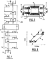
- the refrigerator illustrated in figure 1 uses a working circuit 200 of a working gas comprising the components listed below.
- Circuit 200 comprises several centrifugal compressors 3, 5, 7 arranged in series and operating at room temperature.
- the circuit 200 comprises several heat exchangers 2, 4, 6 operating at ambient temperature arranged respectively at the outlet of the compressors 3, 5, 7.
- the temperatures of the working gas at the inlet and outlet of each compression stage i.e. at the inlet and outlet of each compressor 3, 5, 7) are maintained by the heat exchanges at a substantially identical level (see zone A on the figure 3 which represents a gas work cycle: temperature in K as a function of the entropy S in J/kg).
- zone A on the figure 3 which represents a gas work cycle: temperature in K as a function of the entropy S in J/kg.
- the exchangers 2, 4, 6 may be separate or consist of separate portions of the same exchanger in heat exchange with the hot source 1.
- the refrigerator includes several motors (70 cf. figure 2 ) so-called high-speed motors.
- High-speed motors are usually motors whose rotation speed allows direct coupling with a centrifugal compression stage or a centripetal expansion stage.
- High-speed motors 70 preferably use magnetic or dynamic gas bearings 171 ( figure 2 ).
- a high-speed motor typically runs at a rotational speed of 10,000 revolutions per minute or several tens of thousands of revolutions per minute.
- a low-speed motor typically runs at a speed of a few thousand revolutions per minute.
- the refrigerator Downstream of the compression portion comprising the compressors in series, the refrigerator comprises a heat exchanger 8 preferably of the counter-current plate type separating the elements at room temperature (in the upper part of the circuit 200 shown in FIG. figure 1 ) cryogenic temperature elements (in the lower part of the circuit 200).
- the fluid is cooled (corresponding to zone D of the figure 3 ).
- the cooling of the gas from ambient temperature to cryogenic temperature is carried out by countercurrent exchange with the same working gas at cryogenic temperature which returns from the expansion portion after heat exchange with the cold source 15.
- the circuit Downstream of this cooling portion constituted by the plate exchanger 8, the circuit comprises one or more expansion turbines 9, 11, 13, preferably of the centripetal type, arranged in series.
- the turbines 9, 11, 13 operate at cryogenic temperatures, the inlet and outlet temperatures of each expansion stage (turbine inlet and outlet) are maintained substantially identical by one or more cryogenic heat exchangers 10, 12, 14 arranged at the outlet of the turbine(s).
- the descending portions of zone C each corresponding to an expansion stage while the rising portions of this zone correspond to the heating in the exchangers 10, 12, 14.
- This arrangement makes it possible to approach an isothermal expansion.
- the inlet and outlet temperatures of each expansion stage are substantially the same.
- the increase in the temperature of the working gas in the exchanger(s) (10, 12, 14) may be substantially identical (in absolute value) to the drop in the temperature of the fluid to be cooled (15) (cold source).
- heating exchangers 10, 12, 14 may be separate or consist of separate portions of the same exchanger in heat exchange with the cold source 15.
- the working fluid exchanges heat again with the plate heat exchanger 8 (zone B of the figure 3 ).
- the fluid exchanges heat in the exchanger 8 in counter-current with respect to its passage after the compression portion. After reheating, the fluid returns to the compression portion and can start a cycle again.
- the circuit may further include a capacity for working gas at ambient temperature (not shown for the sake of simplification) to limit the pressure in the circuits, when the refrigerator is switched off for example.
- the refrigerator preferably uses a gaseous phase fluid circulating in a closed circuit as the working fluid.
- a gaseous phase fluid circulating in a closed circuit as the working fluid.
- This consists, for example, of a pure gas or a mixture of pure gases.
- gases best suited to this technology include: helium, neon, nitrogen, oxygen and argon. Carbon monoxide and methane can also be used.
- the refrigerator is designed and controlled in such a way as to obtain a fluid work cycle approaching the reverse Ericsson cycle. That is to say: isothermal compression, isobaric cooling, isothermal expansion and isobaric heating.
- the refrigerator uses several so-called high-speed motors 70 for driving at least the compressors 3, 5, 7 (i.e. for driving the compressor wheels).
- each high-speed 70 engine receives on one end of its output shaft a compressor wheel 31 and, on the other end of its shaft another compressor wheel or a turbine wheel 9.
- This arrangement provides many advantages.
- This configuration allows in the refrigerator a direct coupling between the motor 70 and the compressor wheels 3, 5, 7 or between the motor 70 and the wheels of the turbines 9, 11, 13. This makes it possible to dispense with a speed multiplier or reducer (which limits the number of moving parts required).
- This configuration also allows an enhancement of the mechanical work of the turbine(s) 9, 11, 13 and consequently an increase in the overall energy efficiency of the refrigerator.
- the refrigerator has an oil-free operation, which makes it possible to guarantee the purity of the working gas and eliminates the need for a de-oiling operation.
- the number of high-speed motors is mainly a function of the desired energy efficiency of the refrigerator. The higher the efficiency, the higher the number of high-speed motors should be.
- the ratio between the number of compression stages (compressors) and the number of expansion stages (turbines) is a function of the target cold temperature. For example, for an unclaimed refrigerator with a cold source at 273 K, the number of compression stages will be substantially equal to the number of expansion stages. For a refrigerator with a cold source at 65 K, the number of compression stages is approximately 3 times greater than the number of expansion stages.
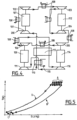
- FIG. 4 illustrates another embodiment which can for example be used to cool or maintain the temperature of superconducting cables at a cryogenic temperature of about 65 K.
- the number of compression stages compressors
- turbines the number of expansion stages (turbines). This can be achieved in several possible configurations. For example three compressors and one turbine or six compressors and two turbines,...
- the refrigerator comprises six compressors 101, 102, 103, 104, 105, 106 and two turbines 116, 111 and four high-speed motors 107, 112, 114, 109.
- the first two compressors 101, 102 i.e., the compressor wheels
- the next two compressors 103, 104 are respectively mounted at both ends of a second high-speed motor 112.
- the next compressor 105 and the turbine 116 i.e., the turbine wheel
- the last turbine 111 and the sixth compressor 106 are respectively mounted at both ends of a fourth motor 109.
- the path of the working gas during a cycle in the closed loop circuit can be described as follows.
- the gas is compressed progressively by passing successively through the four compressors in series 101, 102, 103, 104, 105, 106.
- each compression stage at the outlet of each compressor the working gas is cooled in a respective heat exchanger 108 (by heat exchange with air or water for example) to approach an isothermal compression.
- the gas is cooled isobarically through a counter-current plate exchanger 103.
- the cooling gas is gradually expanded in the two centripetal turbines in series 116, 111.
- the working gas is reheated by heat exchange in an exchanger 110 (for example by heat exchange with the cold source), so as to achieve a substantially isothermal expansion.
- the working gas is reheated in the exchanger 113 and can then start a new cycle by compression.
- FIG 5 represents the cycle (temperature T and entropy S) of the working fluid of the refrigerator of the figure 5 .
- compression zone A we can see six saw teeth corresponding to the six successive compressions and coolings.
- relaxation zone C we can see two saw teeth corresponding to the two successive relaxations and heatings.
- the invention improves cryogenic refrigerators in terms of energy efficiency, reliability and size.
- the invention makes it possible to reduce maintenance operations and eliminate the use of oils.
- one or both ends of the output shafts of the engine(s) can directly drive more than one route (i.e. multiple compressors or multiple turbines).
Landscapes
- Engineering & Computer Science (AREA)
- Physics & Mathematics (AREA)
- Mechanical Engineering (AREA)
- Thermal Sciences (AREA)
- General Engineering & Computer Science (AREA)
- Health & Medical Sciences (AREA)
- Chemical & Material Sciences (AREA)
- Chemical Kinetics & Catalysis (AREA)
- Emergency Medicine (AREA)
- Clinical Laboratory Science (AREA)
- Structures Of Non-Positive Displacement Pumps (AREA)
- Separation By Low-Temperature Treatments (AREA)
Claims (7)
- Kryogene Kühlvorrichtung, die dazu bestimmt ist, über ein Arbeitsfluid, das in einem geschlossenen Arbeitskreislauf (200) zirkuliert, Wärme von einer kalten Quelle (15) zu einer heißen Quelle (1) zu übertragen,
wobei der Arbeitskreislauf (200) seriell Folgendes umfasst:einen im Wesentlichen isothermen Kompressionsabschnitt des Fluids, einen im Wesentlichen isobaren Kühlabschnitt des Fluids,einen im Wesentlichen isothermen Expansionsabschnitt des Fluids und einen im Wesentlichen isobaren Erwärmungsabschnitt des Fluids,wobei der Kompressionsabschnitt des Arbeitskreislaufs (200) mindestens zwei seriell angeordnete Kompressoren (7, 5, 3, 101, 102, 103, 104, 105, 106) und mindestens einen am Ausgang jedes Kompressors (7, 5, 3, 101, 102, 103, 104, 105, 106) angeordneten Tauscher (6, 4, 2, 108) zum Kühlen des komprimierten Fluids umfasst,wobei der Expansionsabschnitt des Arbeitskreislaufs (200) mindestens eine Expansionsturbine (9, 11, 13, 116, 111) und mindestens einen Tauscher (10, 12, 14, 110) zum Erwärmen des expandierten Fluids umfasst,wobei die Kompressoren (7, 5, 3, 101, 102, 103, 104, 105, 106) und die Entspannungsturbine(n) (9, 11, 13) von mehreren sogenannten Hochgeschwindigkeitsmotoren (70, 107, 112, 114, 109) angetrieben werden, die mit einer Drehzahl von 10.000 Umdrehungen pro Minute oder mehreren Zehntausend Umdrehungen pro Minute rotieren,wobei jeder Motor eine Abtriebswelle umfasst, deren eines Ende einen ersten Kompressor (7, 5, 3, 101, 102, 103, 104, 105, 106) trägt und durch direkte Kopplung in Rotation versetzt und deren anderes Ende einen zweiten Kompressor oder eine Expansionsturbine (9, 11, 13, 116, 111) trägt und durch direkte Kopplung in Rotation versetzt,wobei die Kompressoren (7, 5, 3, 101, 102, 103, 104, 105, 106) vom Typ der Zentrifugalkompression sind,wobei die Expansionsturbine(n) (9, 11, 13, 116, 111) vom Typ der Zentripetalexpansion sind,wobei die Abtriebswellen (71) der Motoren (70, 107, 112, 114, 109) auf Lagern (171) vom magnetischen oder gasdynamischen Typ montiert sind,wobei die Lager (171) zur Abstützung der Kompressoren (7, 5, 3, 101, 102, 103, 104, 105, 106) und der Turbine(n) (9, 11, 13, 116, 111) verwendet werden,wobei der Kühlabschnitt und der Erwärmungsabschnitt einen gemeinsamen Wärmetauscher (8, 113) umfassen, in dem das Arbeitsfluid in Abhängigkeit davon, ob es gekühlt oder erwärmt wird, im Gegenstrom fließt,dadurch gekennzeichnet, dass die Anzahl der Kompressionsstufen, d. h. der Kompressoren, größer ist als die Anzahl der Expansionsstufen, d. h. der seriell angeordneten Kompressoren. - Vorrichtung nach Anspruch 1, dadurch gekennzeichnet, dass der Arbeitskreislauf ein Volumen umfasst, das eine Pufferkapazität zur Speicherung des Arbeitsfluids bildet.
- Vorrichtung nach Anspruch 1 oder 2, dadurch gekennzeichnet, dass sich das Arbeitsfluid in der Gasphase befindet und aus einem reinen Gas oder einem Gemisch aus reinen Gasen aus: Helium, Neon, Stickstoff, Sauerstoff, Argon, Kohlenmonoxid, Methan, oder einem anderen Fluid, das bei der Temperatur der kalten Quelle eine Gasphase aufweist, gebildet ist.
- Kryogenes Kühlverfahren, das dazu bestimmt ist, über ein Arbeitsfluid, das in einem geschlossenen Arbeitskreislauf (200) zirkuliert, Wärme von einer kalten Quelle (15) zu einer heißen Quelle (1) zu übertragen,
wobei der Arbeitskreislauf (200) seriell Folgendes umfasst:einen Kompressionsabschnitt, der mindestens zwei seriell angeordnete Kompressoren (7, 5, 3, 101, 102, 103, 104, 105, 106) umfasst,einen Kühlabschnitt des Fluids, einen Expansionsabschnitt, der mindestens eine Expansionsturbine (9, 11, 13, 116, 111) umfasst, und einen Erwärmungsabschnitt,wobei das Verfahren einen Arbeitszyklus umfasst, der folgende Schritte beinhaltet:einen ersten Schritt der im Wesentlichen isothermen Kompression des Fluids im Kompressionsabschnitt durch Kühlen des komprimieren Fluids am Ausgang der Kompressoren (7, 5, 3, 101, 102, 103, 104, 105, 106), einen zweiten Schritt der im Wesentlichen isobaren Kühlung des Fluids im Kühlabschnitt,einen dritten Schritt der im Wesentlichen isothermen Expansion des Fluids im Expansionsabschnitt durch Erwärmen des expandierten Fluids am Ausgang der Turbine(n) undeinen vierten Schritt der im Wesentlichen isobaren Erwärmung des Fluids, das mit der kalten Quelle (15) Wärme ausgetauscht hat,wobei der Arbeitszyklus des Fluids (Temperatur T, Entropie S) während des ersten Schritts der im Wesentlichen isothermen Kompression vom inversen Ericsson-Typ ist,wobei das komprimierte Fluid am Ausgang jedes Kompressors (7, 5, 3, 101, 102, 103, 104, 105, 106) gekühlt wird, um die Temperaturen des Fluids am Eingang und am Ausgang jedes Kompressors im Wesentlichen gleich und vorzugsweise in einem Bereich von etwa 10 K zu halten,wobei während des dritten Schritts der im Wesentlichen isothermen Expansion das expandierte Fluid am Ausgang jeder Turbine (9, 11, 13, 116, 111) erwärmt wird, um die Temperaturen des Fluids am Eingang und am Ausgang jeder Turbine (9, 11, 13, 116, 111) im Wesentlichen in einem Bereich von etwa 5 K gleich zu halten,wobei die Kompressoren (7, 5, 3, 101, 102, 103, 104, 105, 106) und die Expansionsturbine(n) (9, 11, 13, 116, 111) von mehreren sogenannten Hochgeschwindigkeitsmotoren (70, 107, 112, 114, 109) angetrieben werden, die mit einer Drehzahl von 10.000 Umdrehungen pro Minute oder mehreren Zehntausend Umdrehungen pro Minute rotieren,wobei jeder Motor eine Abtriebswelle umfasst, deren eines Ende einen ersten Kompressor (7, 5, 3, 101, 102, 103, 104, 105, 106) trägt und durch direkte Kopplung in Rotation versetzt und deren anderes Ende einen Kompressor oder eine Expansionsturbine (9, 11, 13, 116, 111) trägt und durch direkte Kopplung in Rotation versetzt,wobei das Verfahren einen Schritt umfasst, bei dem ein Teil der mechanischen Arbeit der Turbine(n) (9, 11, 13, 116, 111) über die Abtriebswelle(n) (71) auf den Kompressor bzw. die Kompressoren (7, 5, 3, 101, 102, 103, 104, 105, 106) übertragen wird,wobei die Abtriebswellen (71) der Motoren (70, 107, 112, 114, 109) auf Lagern (171) vom magnetischen oder gasdynamischen Typ montiert sind,wobei die Lager (171) zur Abstützung der Kompressoren und Turbinen verwendet werden,wobei der Kühlabschnitt und der Erwärmungsabschnitt einen gemeinsamen Wärmetauscher (8, 113) umfassen, in dem das Arbeitsfluid in Abhängigkeit davon, ob es gekühlt oder erwärmt wird, im Gegenstrom fließt, wobei die Anzahl der Kompressionsstufen, d. h. der Kompressoren, größer ist als die Anzahl der Expansionsstufen, d. h. der Turbinen. - Verfahren nach Anspruch 4, dadurch gekennzeichnet, dass am Ende des zweiten Schritts des Kühlens das Arbeitsfluid auf eine niedrige Temperatur im Bereich von etwa 60 K gebracht wird, und dadurch, dass der Arbeitskreislauf (200) eine Anzahl von Kompressoren (7, 5, 3, 101, 102, 103, 104, 105, 106) umfasst, die dreimal so groß wie die Anzahl der Expansionsturbinen (9, 11, 13, 116, 111) ist.
- Verfahren nach einem der Ansprüche 4 oder 5, dadurch gekennzeichnet, dass das Arbeitsfluid zum Kühlen oder Kühlhalten von supraleitenden Elementen auf eine(r) Temperatur im Bereich von 65 K verwendet wird.
- Verfahren nach einem der Ansprüche 4 bis 6, dadurch gekennzeichnet, dass der Temperaturabfall des Fluids, das die kalte Quelle (15) bildet, im Wesentlichen gleich dem Temperaturanstieg des Arbeitsgases in den Wärmetauschern (110, 10, 12, 14) des Arbeitskreislaufs (200) ist.
Priority Applications (3)
| Application Number | Priority Date | Filing Date | Title |
|---|---|---|---|
| EP18178529.6A EP3410035A1 (de) | 2007-11-23 | 2008-10-23 | Vorrichtung und verfahren zur kryogenen kühlung |
| EP19174805.2A EP3561411A1 (de) | 2007-11-23 | 2008-10-23 | Vorrichtung und verfahren zur kryogenen kühlung |
| PL08852903.7T PL2225501T5 (pl) | 2007-11-23 | 2008-10-23 | Urządzenie i sposób chłodzenia kriogenicznego |
Applications Claiming Priority (2)
| Application Number | Priority Date | Filing Date | Title |
|---|---|---|---|
| FR0759243A FR2924205B1 (fr) | 2007-11-23 | 2007-11-23 | Dispositif et procede de refrigeration cryogenique |
| PCT/FR2008/051919 WO2009066044A2 (fr) | 2007-11-23 | 2008-10-23 | Dispositif et procede de refrigeration cryogenique |
Related Child Applications (4)
| Application Number | Title | Priority Date | Filing Date |
|---|---|---|---|
| EP18178529.6A Division EP3410035A1 (de) | 2007-11-23 | 2008-10-23 | Vorrichtung und verfahren zur kryogenen kühlung |
| EP18178529.6A Division-Into EP3410035A1 (de) | 2007-11-23 | 2008-10-23 | Vorrichtung und verfahren zur kryogenen kühlung |
| EP19174805.2A Division EP3561411A1 (de) | 2007-11-23 | 2008-10-23 | Vorrichtung und verfahren zur kryogenen kühlung |
| EP19174805.2A Division-Into EP3561411A1 (de) | 2007-11-23 | 2008-10-23 | Vorrichtung und verfahren zur kryogenen kühlung |
Publications (3)
| Publication Number | Publication Date |
|---|---|
| EP2225501A2 EP2225501A2 (de) | 2010-09-08 |
| EP2225501B1 EP2225501B1 (de) | 2018-09-05 |
| EP2225501B2 true EP2225501B2 (de) | 2025-01-15 |
Family
ID=39691274
Family Applications (3)
| Application Number | Title | Priority Date | Filing Date |
|---|---|---|---|
| EP19174805.2A Withdrawn EP3561411A1 (de) | 2007-11-23 | 2008-10-23 | Vorrichtung und verfahren zur kryogenen kühlung |
| EP18178529.6A Ceased EP3410035A1 (de) | 2007-11-23 | 2008-10-23 | Vorrichtung und verfahren zur kryogenen kühlung |
| EP08852903.7A Active EP2225501B2 (de) | 2007-11-23 | 2008-10-23 | Kryogenes kühlverfahren und entsprechende vorrichtung |
Family Applications Before (2)
| Application Number | Title | Priority Date | Filing Date |
|---|---|---|---|
| EP19174805.2A Withdrawn EP3561411A1 (de) | 2007-11-23 | 2008-10-23 | Vorrichtung und verfahren zur kryogenen kühlung |
| EP18178529.6A Ceased EP3410035A1 (de) | 2007-11-23 | 2008-10-23 | Vorrichtung und verfahren zur kryogenen kühlung |
Country Status (12)
| Country | Link |
|---|---|
| US (1) | US20100263405A1 (de) |
| EP (3) | EP3561411A1 (de) |
| JP (1) | JP2011504574A (de) |
| KR (1) | KR20100099129A (de) |
| CN (1) | CN101868677B (de) |
| DK (1) | DK2225501T4 (de) |
| ES (1) | ES2693066T5 (de) |
| FI (1) | FI2225501T4 (de) |
| FR (1) | FR2924205B1 (de) |
| HU (1) | HUE040042T2 (de) |
| PL (1) | PL2225501T5 (de) |
| WO (1) | WO2009066044A2 (de) |
Families Citing this family (28)
| Publication number | Priority date | Publication date | Assignee | Title |
|---|---|---|---|---|
| FR2951815B1 (fr) * | 2009-10-27 | 2012-09-07 | Technip France | Procede de fractionnement d'un courant de gaz craque pour obtenir une coupe riche en ethylene et un courant de combustible, et installation associee. |
| CN102638983B (zh) | 2009-11-06 | 2014-11-26 | 阿尔皮奥治疗学股份有限公司 | 用于治疗结肠炎的组合物和方法 |
| DE102011013345A1 (de) * | 2011-03-08 | 2012-09-13 | Linde Aktiengesellschaft | Kälteanlage |
| FR2977014B1 (fr) * | 2011-06-24 | 2016-04-15 | Saipem Sa | Procede de liquefaction de gaz naturel avec un melange de gaz refrigerant. |
| FR2977015B1 (fr) * | 2011-06-24 | 2015-07-03 | Saipem Sa | Procede de liquefaction de gaz naturel a triple circuit ferme de gaz refrigerant |
| FR2980564A1 (fr) * | 2011-09-23 | 2013-03-29 | Air Liquide | Procede et installation de refrigeration |
| FR2981982B1 (fr) * | 2011-10-28 | 2013-11-01 | IFP Energies Nouvelles | Procede de controle d'un circuit ferme fonctionnant selon un cycle rankine et circuit utilisant un tel procede |
| US9234480B2 (en) | 2012-07-04 | 2016-01-12 | Kairama Inc. | Isothermal machines, systems and methods |
| US20140186170A1 (en) * | 2012-12-27 | 2014-07-03 | Ronald E. Graf | Centrifugal Expanders And Compressors Each Using Rotors In Both Flow Going From Periphery To Center And Flow Going From Center To Periphery Their Use In Engines Both External Heat And Internal Combustion. Means to convert radial inward flow to radial outward flow with less eddy currents |
| US10072665B1 (en) | 2012-12-27 | 2018-09-11 | Ronald E. Graf | Multistage compressors and reverse compressors comprising a series of centrifugal pumps alternating flow toward and away from axle with better flow transitions between stages |
| FR3014543B1 (fr) * | 2013-12-06 | 2018-11-09 | L'air Liquide, Societe Anonyme Pour L'etude Et L'exploitation Des Procedes Georges Claude | Dispositif et procede de refroidissement et/ou de liquefaction a basse temperature |
| FR3047551B1 (fr) | 2016-02-08 | 2018-01-26 | L'air Liquide, Societe Anonyme Pour L'etude Et L'exploitation Des Procedes Georges Claude | Dispositif de refrigeration cryogenique |
| CN106121743B (zh) * | 2016-08-18 | 2017-07-14 | 开封空分集团有限公司 | 一种液体向心透平能量回收装置 |
| FR3055692B1 (fr) | 2016-09-06 | 2018-08-24 | L'air Liquide, Societe Anonyme Pour L'etude Et L'exploitation Des Procedes Georges Claude | Installation, procede pour stocker et reliquefier un gaz liquefie et vehicule de transport associe |
| IT201600109378A1 (it) * | 2016-10-28 | 2018-04-28 | Nuovo Pignone Tecnologie Srl | Sistema di liquefazione di gas naturale comprendente un turbocompressore con moltiplicatore integrato |
| SG11201908182VA (en) * | 2017-03-14 | 2019-10-30 | Woodside Energy Technologies Pty Ltd | A containerised lng liquefaction unit and associated method of producing lng |
| CN107477898A (zh) * | 2017-08-11 | 2017-12-15 | 北京理工大学 | 一种多级串联式大型低温制冷系统 |
| FR3072160B1 (fr) * | 2017-10-09 | 2019-10-04 | L'air Liquide Societe Anonyme Pour L'etude Et L'exploitation Des Procedes Georges Claude | Dispositif et procede de refrigeration |
| CN108775723A (zh) * | 2018-06-27 | 2018-11-09 | 芜湖盘云石磨新能源科技有限公司 | 一种二氧化碳制冷装置 |
| JP7141342B2 (ja) * | 2019-01-31 | 2022-09-22 | 大陽日酸株式会社 | 極低温流体循環式冷却システム及び極低温流体循環式冷却方法 |
| JP6926153B2 (ja) * | 2019-07-03 | 2021-08-25 | 大陽日酸株式会社 | 超電導体の冷却装置及び超電導体の冷却方法 |
| FR3098574B1 (fr) * | 2019-07-10 | 2021-06-25 | Air Liquide | Dispositif de réfrigération et/ou de liquéfaction |
| FR3099820B1 (fr) * | 2019-08-05 | 2022-11-04 | Air Liquide | Dispositif et installation de réfrigération |
| FR3099818B1 (fr) * | 2019-08-05 | 2022-11-04 | Air Liquide | Dispositif de réfrigération et installation et procédé de refroidissement et/ou de liquéfaction |
| WO2022033714A1 (en) * | 2020-08-12 | 2022-02-17 | Cryostar Sas | Simplified cryogenic refrigeration system |
| KR102458455B1 (ko) | 2020-11-03 | 2022-10-26 | 한국기계연구원 | 터보기계용 진공 중공축 제작장치, 상기 제작장치를 이용하여 터보기계용 진공 중공축을 제작하는 방법, 상기 방법에 의해 제작된 진공 중공축을 구비한 터보기계 |
| FR3119668B1 (fr) | 2021-02-10 | 2023-11-10 | Air Liquide | Dispositif et procédé de réfrigération ou de liquéfaction d’un fluide. |
| FR3119667B1 (fr) * | 2021-02-10 | 2023-03-24 | Air Liquide | Dispositif et procédé de liquéfaction d’un fluide tel que l’hydrogène et/ou de l’hélium |
Family Cites Families (36)
| Publication number | Priority date | Publication date | Assignee | Title |
|---|---|---|---|---|
| NL287922A (de) * | 1962-02-12 | |||
| US3494145A (en) * | 1968-06-10 | 1970-02-10 | Worthington Corp | Integral turbo compressor-expander system for refrigeration |
| FR2165729B1 (de) * | 1971-12-27 | 1976-02-13 | Technigaz Fr | |
| GB1510629A (en) * | 1974-08-08 | 1978-05-10 | Penny Turbines Ltd N | Centrifugal compressor or centripetal turbine |
| DE2440215A1 (de) * | 1974-08-22 | 1976-03-04 | Linde Ag | Verfahren zum verfluessigen und unterkuehlen eines tiefsiedenden gases |
| US3992167A (en) * | 1975-04-02 | 1976-11-16 | Union Carbide Corporation | Low temperature refrigeration process for helium or hydrogen mixtures using mixed refrigerant |
| JPS6079125A (ja) * | 1983-10-05 | 1985-05-04 | Kiichi Taga | 等温圧縮機を利用するクロ−ズドサイクル動力伝達方式 |
| JPS6251723A (ja) * | 1985-08-29 | 1987-03-06 | Isuzu Motors Ltd | 超高速電動−発電機 |
| GB8625391D0 (en) * | 1986-10-23 | 1986-11-26 | Crane Packing Ltd | Mechanical face seals |
| US4984432A (en) * | 1989-10-20 | 1991-01-15 | Corey John A | Ericsson cycle machine |
| JPH03286968A (ja) * | 1990-03-31 | 1991-12-17 | Aisin Seiki Co Ltd | 極低温冷凍装置 |
| JPH0781754B2 (ja) * | 1990-06-28 | 1995-09-06 | 新技術事業団 | 冷凍機 |
| NO910827D0 (no) * | 1991-03-01 | 1991-03-01 | Sinvent As Sintef Gruppen | Flertrinns-tannhjulsmaskin for kompresjon eller ekspansjon av gass. |
| FR2679635B1 (fr) * | 1991-07-26 | 1993-10-15 | Air Liquide | Circuit de compression d'un fluide gazeux a basse pression et a basse temperature. |
| US5248239A (en) * | 1992-03-19 | 1993-09-28 | Acd, Inc. | Thrust control system for fluid handling rotary apparatus |
| US5310311A (en) * | 1992-10-14 | 1994-05-10 | Barber-Colman Company | Air cycle machine with magnetic bearings |
| US5473899A (en) * | 1993-06-10 | 1995-12-12 | Viteri; Fermin | Turbomachinery for Modified Ericsson engines and other power/refrigeration applications |
| US5590528A (en) * | 1993-10-19 | 1997-01-07 | Viteri; Fermin | Turbocharged reciprocation engine for power and refrigeration using the modified Ericsson cycle |
| US5495718A (en) * | 1994-01-14 | 1996-03-05 | Pierce; James G. | Refrigeration of superconducting magnet systems |
| JPH09329034A (ja) * | 1996-06-11 | 1997-12-22 | Ishikawajima Harima Heavy Ind Co Ltd | 閉サイクルガスタービン |
| JP3928230B2 (ja) * | 1997-12-01 | 2007-06-13 | 石川島播磨重工業株式会社 | 冷凍機用の回転機械 |
| US6354087B1 (en) * | 1998-05-22 | 2002-03-12 | Sumitomo Electric Industries, Ltd | Method and apparatus for cooling superconductor |
| JP2001041598A (ja) * | 1999-07-30 | 2001-02-16 | Mitsubishi Heavy Ind Ltd | 多段圧縮冷凍機 |
| GB0001801D0 (en) * | 2000-01-26 | 2000-03-22 | Cryostar France Sa | Apparatus for reliquiefying compressed vapour |
| JP2003148824A (ja) * | 2001-11-13 | 2003-05-21 | Daikin Ind Ltd | 空気調和装置 |
| CA2373905A1 (en) * | 2002-02-28 | 2003-08-28 | Ronald David Conry | Twin centrifugal compressor |
| US6948314B2 (en) * | 2003-09-12 | 2005-09-27 | Honeywell International, Inc. | High response, compact turbocharger |
| WO2006011248A1 (ja) * | 2004-07-30 | 2006-02-02 | Mitsubishi Heavy Industries, Ltd. | 空気冷媒式冷却装置および空気冷媒式冷却装置を用いた空気冷媒冷熱システム |
| JP4335115B2 (ja) * | 2004-10-20 | 2009-09-30 | 鹿島建設株式会社 | 空気冷媒式冷凍装置 |
| CN2795751Y (zh) * | 2005-04-21 | 2006-07-12 | 北京航空航天大学 | 高速电机驱动的高效空气制冷机 |
| CN1952529A (zh) * | 2005-10-19 | 2007-04-25 | 周凌云 | 制冷装置及其制冷方法 |
| JP2007162724A (ja) * | 2005-12-09 | 2007-06-28 | Ntn Corp | モータ一体型磁気軸受装置 |
| US7723883B2 (en) * | 2005-12-09 | 2010-05-25 | Ntn Corporation | Motor built-in magnetic bearing device |
| JP4779741B2 (ja) * | 2006-03-22 | 2011-09-28 | 株式会社日立製作所 | ヒートポンプシステム,ヒートポンプシステムの軸封方法,ヒートポンプシステムの改造方法 |
| JP4779761B2 (ja) * | 2006-03-30 | 2011-09-28 | 株式会社ジェイテクト | 燃料電池用圧縮機 |
| JP2007303792A (ja) * | 2006-05-15 | 2007-11-22 | Sanyo Electric Co Ltd | 冷凍装置 |
-
2007
- 2007-11-23 FR FR0759243A patent/FR2924205B1/fr active Active
-
2008
- 2008-10-23 DK DK08852903.7T patent/DK2225501T4/da active
- 2008-10-23 EP EP19174805.2A patent/EP3561411A1/de not_active Withdrawn
- 2008-10-23 EP EP18178529.6A patent/EP3410035A1/de not_active Ceased
- 2008-10-23 PL PL08852903.7T patent/PL2225501T5/pl unknown
- 2008-10-23 ES ES08852903T patent/ES2693066T5/es active Active
- 2008-10-23 FI FIEP08852903.7T patent/FI2225501T4/fi active
- 2008-10-23 JP JP2010534519A patent/JP2011504574A/ja active Pending
- 2008-10-23 HU HUE08852903A patent/HUE040042T2/hu unknown
- 2008-10-23 US US12/742,751 patent/US20100263405A1/en not_active Abandoned
- 2008-10-23 WO PCT/FR2008/051919 patent/WO2009066044A2/fr not_active Ceased
- 2008-10-23 CN CN2008801166825A patent/CN101868677B/zh active Active
- 2008-10-23 EP EP08852903.7A patent/EP2225501B2/de active Active
- 2008-10-23 KR KR1020107011068A patent/KR20100099129A/ko not_active Ceased
Also Published As
| Publication number | Publication date |
|---|---|
| EP3561411A1 (de) | 2019-10-30 |
| HUE040042T2 (hu) | 2019-02-28 |
| WO2009066044A4 (fr) | 2009-09-11 |
| FI2225501T4 (fi) | 2025-03-17 |
| FR2924205B1 (fr) | 2013-08-16 |
| ES2693066T5 (en) | 2025-04-21 |
| CN101868677A (zh) | 2010-10-20 |
| ES2693066T3 (es) | 2018-12-07 |
| WO2009066044A3 (fr) | 2009-07-16 |
| WO2009066044A2 (fr) | 2009-05-28 |
| EP2225501A2 (de) | 2010-09-08 |
| PL2225501T5 (pl) | 2025-04-28 |
| PL2225501T3 (pl) | 2019-02-28 |
| EP3410035A1 (de) | 2018-12-05 |
| DK2225501T3 (en) | 2018-11-19 |
| US20100263405A1 (en) | 2010-10-21 |
| FR2924205A1 (fr) | 2009-05-29 |
| EP2225501B1 (de) | 2018-09-05 |
| DK2225501T4 (da) | 2025-03-10 |
| KR20100099129A (ko) | 2010-09-10 |
| JP2011504574A (ja) | 2011-02-10 |
| CN101868677B (zh) | 2012-10-03 |
Similar Documents
| Publication | Publication Date | Title |
|---|---|---|
| EP2225501B2 (de) | Kryogenes kühlverfahren und entsprechende vorrichtung | |
| EP3414498B1 (de) | Kryogene kühlvorrichtung | |
| WO2021023458A1 (fr) | Installation et procede de refroidissement et/ou de liquefaction | |
| EP4291838B1 (de) | Vorrichtung und verfahren zur verflüssigung eines fluids wie wasserstoff und/oder helium | |
| WO2021023459A1 (fr) | Dispositif et installation de réfrigération | |
| EP4010640A1 (de) | Kühlvorrichtung und system | |
| EP3698048B1 (de) | Kompressionsvorrichtung und -verfahren und kältemaschine | |
| FR3098574A1 (fr) | Dispositif de réfrigération et/ou de liquéfaction | |
| WO2022171485A1 (fr) | Dispositif et procédé de liquéfaction d'un fluide tel que l'hydrogène et/ou de l'hélium | |
| EP4490453B1 (de) | Fluidzirkulationsvorrichtung, anlage und verfahren mit solch einer vorrichtung | |
| EP4551876A1 (de) | Verfahren und vorrichtung zur verflüssigung von flüssigkeiten | |
| FR3106943A1 (fr) | Dispositif de refroidissement de rotor et machine tournante le comportant | |
| WO2025002660A1 (fr) | Installation et procédé de liquéfaction d'un fluide | |
| WO2022171394A1 (fr) | Dispositif et procédé de réfrigération ou de liquéfaction d'un fluide |
Legal Events
| Date | Code | Title | Description |
|---|---|---|---|
| PUAI | Public reference made under article 153(3) epc to a published international application that has entered the european phase |
Free format text: ORIGINAL CODE: 0009012 |
|
| 17P | Request for examination filed |
Effective date: 20100623 |
|
| AK | Designated contracting states |
Kind code of ref document: A2 Designated state(s): AT BE BG CH CY CZ DE DK EE ES FI FR GB GR HR HU IE IS IT LI LT LU LV MC MT NL NO PL PT RO SE SI SK TR |
|
| AX | Request for extension of the european patent |
Extension state: AL BA MK RS |
|
| DAX | Request for extension of the european patent (deleted) | ||
| STAA | Information on the status of an ep patent application or granted ep patent |
Free format text: STATUS: EXAMINATION IS IN PROGRESS |
|
| 17Q | First examination report despatched |
Effective date: 20170523 |
|
| REG | Reference to a national code |
Ref country code: DE Ref legal event code: R079 Ref document number: 602008056871 Country of ref document: DE Free format text: PREVIOUS MAIN CLASS: F25B0001100000 Ipc: F25J0001020000 |
|
| GRAP | Despatch of communication of intention to grant a patent |
Free format text: ORIGINAL CODE: EPIDOSNIGR1 |
|
| RIC1 | Information provided on ipc code assigned before grant |
Ipc: F25B 9/10 20060101ALI20171010BHEP Ipc: F25B 1/10 20060101ALI20171010BHEP Ipc: F25B 9/06 20060101ALI20171010BHEP Ipc: F25J 1/00 20060101ALI20171010BHEP Ipc: F25J 1/02 20060101AFI20171010BHEP Ipc: F25B 9/14 20060101ALI20171010BHEP |
|
| STAA | Information on the status of an ep patent application or granted ep patent |
Free format text: STATUS: GRANT OF PATENT IS INTENDED |
|
| INTG | Intention to grant announced |
Effective date: 20171116 |
|
| TPAC | Observations filed by third parties |
Free format text: ORIGINAL CODE: EPIDOSNTIPA |
|
| GRAJ | Information related to disapproval of communication of intention to grant by the applicant or resumption of examination proceedings by the epo deleted |
Free format text: ORIGINAL CODE: EPIDOSDIGR1 |
|
| STAA | Information on the status of an ep patent application or granted ep patent |
Free format text: STATUS: EXAMINATION IS IN PROGRESS |
|
| INTC | Intention to grant announced (deleted) | ||
| GRAP | Despatch of communication of intention to grant a patent |
Free format text: ORIGINAL CODE: EPIDOSNIGR1 |
|
| STAA | Information on the status of an ep patent application or granted ep patent |
Free format text: STATUS: GRANT OF PATENT IS INTENDED |
|
| GRAS | Grant fee paid |
Free format text: ORIGINAL CODE: EPIDOSNIGR3 |
|
| GRAA | (expected) grant |
Free format text: ORIGINAL CODE: 0009210 |
|
| STAA | Information on the status of an ep patent application or granted ep patent |
Free format text: STATUS: THE PATENT HAS BEEN GRANTED |
|
| INTG | Intention to grant announced |
Effective date: 20180712 |
|
| AK | Designated contracting states |
Kind code of ref document: B1 Designated state(s): AT BE BG CH CY CZ DE DK EE ES FI FR GB GR HR HU IE IS IT LI LT LU LV MC MT NL NO PL PT RO SE SI SK TR |
|
| REG | Reference to a national code |
Ref country code: GB Ref legal event code: FG4D Free format text: NOT ENGLISH |
|
| REG | Reference to a national code |
Ref country code: CH Ref legal event code: EP |
|
| REG | Reference to a national code |
Ref country code: AT Ref legal event code: REF Ref document number: 1038310 Country of ref document: AT Kind code of ref document: T Effective date: 20180915 |
|
| REG | Reference to a national code |
Ref country code: IE Ref legal event code: FG4D Free format text: LANGUAGE OF EP DOCUMENT: FRENCH |
|
| REG | Reference to a national code |
Ref country code: DE Ref legal event code: R096 Ref document number: 602008056871 Country of ref document: DE |
|
| REG | Reference to a national code |
Ref country code: FR Ref legal event code: PLFP Year of fee payment: 11 |
|
| REG | Reference to a national code |
Ref country code: RO Ref legal event code: EPE |
|
| REG | Reference to a national code |
Ref country code: NL Ref legal event code: FP |
|
| REG | Reference to a national code |
Ref country code: DK Ref legal event code: T3 Effective date: 20181112 |
|
| REG | Reference to a national code |
Ref country code: SE Ref legal event code: TRGR |
|
| REG | Reference to a national code |
Ref country code: NO Ref legal event code: T2 Effective date: 20180905 |
|
| REG | Reference to a national code |
Ref country code: ES Ref legal event code: FG2A Ref document number: 2693066 Country of ref document: ES Kind code of ref document: T3 Effective date: 20181207 |
|
| REG | Reference to a national code |
Ref country code: LT Ref legal event code: MG4D |
|
| PG25 | Lapsed in a contracting state [announced via postgrant information from national office to epo] |
Ref country code: LT Free format text: LAPSE BECAUSE OF FAILURE TO SUBMIT A TRANSLATION OF THE DESCRIPTION OR TO PAY THE FEE WITHIN THE PRESCRIBED TIME-LIMIT Effective date: 20180905 Ref country code: BG Free format text: LAPSE BECAUSE OF FAILURE TO SUBMIT A TRANSLATION OF THE DESCRIPTION OR TO PAY THE FEE WITHIN THE PRESCRIBED TIME-LIMIT Effective date: 20181205 |
|
| REG | Reference to a national code |
Ref country code: AT Ref legal event code: MK05 Ref document number: 1038310 Country of ref document: AT Kind code of ref document: T Effective date: 20180905 |
|
| PG25 | Lapsed in a contracting state [announced via postgrant information from national office to epo] |
Ref country code: LV Free format text: LAPSE BECAUSE OF FAILURE TO SUBMIT A TRANSLATION OF THE DESCRIPTION OR TO PAY THE FEE WITHIN THE PRESCRIBED TIME-LIMIT Effective date: 20180905 Ref country code: HR Free format text: LAPSE BECAUSE OF FAILURE TO SUBMIT A TRANSLATION OF THE DESCRIPTION OR TO PAY THE FEE WITHIN THE PRESCRIBED TIME-LIMIT Effective date: 20180905 |
|
| REG | Reference to a national code |
Ref country code: HU Ref legal event code: AG4A Ref document number: E040042 Country of ref document: HU |
|
| REG | Reference to a national code |
Ref country code: GR Ref legal event code: EP Ref document number: 20180403071 Country of ref document: GR Effective date: 20190225 |
|
| PG25 | Lapsed in a contracting state [announced via postgrant information from national office to epo] |
Ref country code: AT Free format text: LAPSE BECAUSE OF FAILURE TO SUBMIT A TRANSLATION OF THE DESCRIPTION OR TO PAY THE FEE WITHIN THE PRESCRIBED TIME-LIMIT Effective date: 20180905 Ref country code: EE Free format text: LAPSE BECAUSE OF FAILURE TO SUBMIT A TRANSLATION OF THE DESCRIPTION OR TO PAY THE FEE WITHIN THE PRESCRIBED TIME-LIMIT Effective date: 20180905 Ref country code: IS Free format text: LAPSE BECAUSE OF FAILURE TO SUBMIT A TRANSLATION OF THE DESCRIPTION OR TO PAY THE FEE WITHIN THE PRESCRIBED TIME-LIMIT Effective date: 20190105 |
|
| REG | Reference to a national code |
Ref country code: DE Ref legal event code: R026 Ref document number: 602008056871 Country of ref document: DE |
|
| PG25 | Lapsed in a contracting state [announced via postgrant information from national office to epo] |
Ref country code: PT Free format text: LAPSE BECAUSE OF FAILURE TO SUBMIT A TRANSLATION OF THE DESCRIPTION OR TO PAY THE FEE WITHIN THE PRESCRIBED TIME-LIMIT Effective date: 20190105 Ref country code: SK Free format text: LAPSE BECAUSE OF FAILURE TO SUBMIT A TRANSLATION OF THE DESCRIPTION OR TO PAY THE FEE WITHIN THE PRESCRIBED TIME-LIMIT Effective date: 20180905 |
|
| PLBI | Opposition filed |
Free format text: ORIGINAL CODE: 0009260 |
|
| PLAX | Notice of opposition and request to file observation + time limit sent |
Free format text: ORIGINAL CODE: EPIDOSNOBS2 |
|
| PG25 | Lapsed in a contracting state [announced via postgrant information from national office to epo] |
Ref country code: LU Free format text: LAPSE BECAUSE OF NON-PAYMENT OF DUE FEES Effective date: 20181023 |
|
| 26 | Opposition filed |
Opponent name: CRYOSTAR SAS Effective date: 20190527 |
|
| REG | Reference to a national code |
Ref country code: IE Ref legal event code: MM4A |
|
| PG25 | Lapsed in a contracting state [announced via postgrant information from national office to epo] |
Ref country code: MC Free format text: LAPSE BECAUSE OF FAILURE TO SUBMIT A TRANSLATION OF THE DESCRIPTION OR TO PAY THE FEE WITHIN THE PRESCRIBED TIME-LIMIT Effective date: 20180905 |
|
| PG25 | Lapsed in a contracting state [announced via postgrant information from national office to epo] |
Ref country code: SI Free format text: LAPSE BECAUSE OF FAILURE TO SUBMIT A TRANSLATION OF THE DESCRIPTION OR TO PAY THE FEE WITHIN THE PRESCRIBED TIME-LIMIT Effective date: 20180905 |
|
| PLBB | Reply of patent proprietor to notice(s) of opposition received |
Free format text: ORIGINAL CODE: EPIDOSNOBS3 |
|
| PG25 | Lapsed in a contracting state [announced via postgrant information from national office to epo] |
Ref country code: IE Free format text: LAPSE BECAUSE OF NON-PAYMENT OF DUE FEES Effective date: 20181023 |
|
| PG25 | Lapsed in a contracting state [announced via postgrant information from national office to epo] |
Ref country code: MT Free format text: LAPSE BECAUSE OF FAILURE TO SUBMIT A TRANSLATION OF THE DESCRIPTION OR TO PAY THE FEE WITHIN THE PRESCRIBED TIME-LIMIT Effective date: 20180905 |
|
| PG25 | Lapsed in a contracting state [announced via postgrant information from national office to epo] |
Ref country code: TR Free format text: LAPSE BECAUSE OF FAILURE TO SUBMIT A TRANSLATION OF THE DESCRIPTION OR TO PAY THE FEE WITHIN THE PRESCRIBED TIME-LIMIT Effective date: 20180905 |
|
| PG25 | Lapsed in a contracting state [announced via postgrant information from national office to epo] |
Ref country code: CY Free format text: LAPSE BECAUSE OF FAILURE TO SUBMIT A TRANSLATION OF THE DESCRIPTION OR TO PAY THE FEE WITHIN THE PRESCRIBED TIME-LIMIT Effective date: 20180905 |
|
| APAH | Appeal reference modified |
Free format text: ORIGINAL CODE: EPIDOSCREFNO |
|
| APBM | Appeal reference recorded |
Free format text: ORIGINAL CODE: EPIDOSNREFNO |
|
| APBP | Date of receipt of notice of appeal recorded |
Free format text: ORIGINAL CODE: EPIDOSNNOA2O |
|
| APBM | Appeal reference recorded |
Free format text: ORIGINAL CODE: EPIDOSNREFNO |
|
| APBP | Date of receipt of notice of appeal recorded |
Free format text: ORIGINAL CODE: EPIDOSNNOA2O |
|
| PLAB | Opposition data, opponent's data or that of the opponent's representative modified |
Free format text: ORIGINAL CODE: 0009299OPPO |
|
| R26 | Opposition filed (corrected) |
Opponent name: CRYOSTAR SAS Effective date: 20190527 |
|
| APBQ | Date of receipt of statement of grounds of appeal recorded |
Free format text: ORIGINAL CODE: EPIDOSNNOA3O |
|
| PLAB | Opposition data, opponent's data or that of the opponent's representative modified |
Free format text: ORIGINAL CODE: 0009299OPPO |
|
| R26 | Opposition filed (corrected) |
Opponent name: CRYOSTAR SAS Effective date: 20190527 |
|
| PLAB | Opposition data, opponent's data or that of the opponent's representative modified |
Free format text: ORIGINAL CODE: 0009299OPPO |
|
| R26 | Opposition filed (corrected) |
Opponent name: CRYOSTAR SAS Effective date: 20190527 |
|
| RAP4 | Party data changed (patent owner data changed or rights of a patent transferred) |
Owner name: L'AIR LIQUIDE, SOCIETE ANONYME POUR L'ETUDE ET L'EXPLOITATION DES PROCEDES GEORGES CLAUDE |
|
| P01 | Opt-out of the competence of the unified patent court (upc) registered |
Effective date: 20230518 |
|
| PLAB | Opposition data, opponent's data or that of the opponent's representative modified |
Free format text: ORIGINAL CODE: 0009299OPPO |
|
| R26 | Opposition filed (corrected) |
Opponent name: CRYOSTAR SAS Effective date: 20190527 |
|
| APBU | Appeal procedure closed |
Free format text: ORIGINAL CODE: EPIDOSNNOA9O |
|
| PUAH | Patent maintained in amended form |
Free format text: ORIGINAL CODE: 0009272 |
|
| STAA | Information on the status of an ep patent application or granted ep patent |
Free format text: STATUS: PATENT MAINTAINED AS AMENDED |
|
| PGFP | Annual fee paid to national office [announced via postgrant information from national office to epo] |
Ref country code: DE Payment date: 20241021 Year of fee payment: 17 |
|
| PGFP | Annual fee paid to national office [announced via postgrant information from national office to epo] |
Ref country code: NO Payment date: 20241023 Year of fee payment: 17 |
|
| 27A | Patent maintained in amended form |
Effective date: 20250115 |
|
| AK | Designated contracting states |
Kind code of ref document: B2 Designated state(s): AT BE BG CH CY CZ DE DK EE ES FI FR GB GR HR HU IE IS IT LI LT LU LV MC MT NL NO PL PT RO SE SI SK TR |
|
| PGFP | Annual fee paid to national office [announced via postgrant information from national office to epo] |
Ref country code: DK Payment date: 20241025 Year of fee payment: 17 |
|
| REG | Reference to a national code |
Ref country code: DE Ref legal event code: R102 Ref document number: 602008056871 Country of ref document: DE |
|
| PGFP | Annual fee paid to national office [announced via postgrant information from national office to epo] |
Ref country code: BE Payment date: 20241021 Year of fee payment: 17 Ref country code: PL Payment date: 20241015 Year of fee payment: 17 Ref country code: FI Payment date: 20241025 Year of fee payment: 17 Ref country code: GR Payment date: 20241021 Year of fee payment: 17 |
|
| PGFP | Annual fee paid to national office [announced via postgrant information from national office to epo] |
Ref country code: GB Payment date: 20241022 Year of fee payment: 17 |
|
| PGFP | Annual fee paid to national office [announced via postgrant information from national office to epo] |
Ref country code: FR Payment date: 20241021 Year of fee payment: 17 |
|
| PGFP | Annual fee paid to national office [announced via postgrant information from national office to epo] |
Ref country code: CZ Payment date: 20241015 Year of fee payment: 17 |
|
| PGFP | Annual fee paid to national office [announced via postgrant information from national office to epo] |
Ref country code: RO Payment date: 20241015 Year of fee payment: 17 |
|
| PGFP | Annual fee paid to national office [announced via postgrant information from national office to epo] |
Ref country code: IT Payment date: 20241022 Year of fee payment: 17 Ref country code: ES Payment date: 20241127 Year of fee payment: 17 |
|
| PGFP | Annual fee paid to national office [announced via postgrant information from national office to epo] |
Ref country code: SE Payment date: 20241021 Year of fee payment: 17 |
|
| PGFP | Annual fee paid to national office [announced via postgrant information from national office to epo] |
Ref country code: CH Payment date: 20241101 Year of fee payment: 17 |
|
| REG | Reference to a national code |
Ref country code: DK Ref legal event code: T4 Effective date: 20250305 |
|
| REG | Reference to a national code |
Ref country code: NL Ref legal event code: FP |
|
| REG | Reference to a national code |
Ref country code: SE Ref legal event code: RPEO |
|
| REG | Reference to a national code |
Ref country code: ES Ref legal event code: DC2A Ref document number: 2693066 Country of ref document: ES Kind code of ref document: T5 Effective date: 20250421 |
|
| REG | Reference to a national code |
Ref country code: GR Ref legal event code: EP Ref document number: 20250400418 Country of ref document: GR Effective date: 20250409 |
|
| REG | Reference to a national code |
Ref country code: CH Ref legal event code: U11 Free format text: ST27 STATUS EVENT CODE: U-0-0-U10-U11 (AS PROVIDED BY THE NATIONAL OFFICE) Effective date: 20251101 |
|
| PGFP | Annual fee paid to national office [announced via postgrant information from national office to epo] |
Ref country code: HU Payment date: 20251027 Year of fee payment: 18 |
|
| PGFP | Annual fee paid to national office [announced via postgrant information from national office to epo] |
Ref country code: NL Payment date: 20251021 Year of fee payment: 18 |