EP2225092B1 - Vorrichtung und verfahren zur herstellung eines faserverbundwerkstoff-bauteils - Google Patents
Vorrichtung und verfahren zur herstellung eines faserverbundwerkstoff-bauteils Download PDFInfo
- Publication number
- EP2225092B1 EP2225092B1 EP08850878A EP08850878A EP2225092B1 EP 2225092 B1 EP2225092 B1 EP 2225092B1 EP 08850878 A EP08850878 A EP 08850878A EP 08850878 A EP08850878 A EP 08850878A EP 2225092 B1 EP2225092 B1 EP 2225092B1
- Authority
- EP
- European Patent Office
- Prior art keywords
- semi
- mold
- tool mold
- finished product
- tool
- Prior art date
- Legal status (The legal status is an assumption and is not a legal conclusion. Google has not performed a legal analysis and makes no representation as to the accuracy of the status listed.)
- Not-in-force
Links
Images


Classifications
-
- B—PERFORMING OPERATIONS; TRANSPORTING
- B29—WORKING OF PLASTICS; WORKING OF SUBSTANCES IN A PLASTIC STATE IN GENERAL
- B29C—SHAPING OR JOINING OF PLASTICS; SHAPING OF MATERIAL IN A PLASTIC STATE, NOT OTHERWISE PROVIDED FOR; AFTER-TREATMENT OF THE SHAPED PRODUCTS, e.g. REPAIRING
- B29C70/00—Shaping composites, i.e. plastics material comprising reinforcements, fillers or preformed parts, e.g. inserts
- B29C70/04—Shaping composites, i.e. plastics material comprising reinforcements, fillers or preformed parts, e.g. inserts comprising reinforcements only, e.g. self-reinforcing plastics
- B29C70/28—Shaping operations therefor
- B29C70/30—Shaping by lay-up, i.e. applying fibres, tape or broadsheet on a mould, former or core; Shaping by spray-up, i.e. spraying of fibres on a mould, former or core
- B29C70/32—Shaping by lay-up, i.e. applying fibres, tape or broadsheet on a mould, former or core; Shaping by spray-up, i.e. spraying of fibres on a mould, former or core on a rotating mould, former or core
-
- B—PERFORMING OPERATIONS; TRANSPORTING
- B29—WORKING OF PLASTICS; WORKING OF SUBSTANCES IN A PLASTIC STATE IN GENERAL
- B29C—SHAPING OR JOINING OF PLASTICS; SHAPING OF MATERIAL IN A PLASTIC STATE, NOT OTHERWISE PROVIDED FOR; AFTER-TREATMENT OF THE SHAPED PRODUCTS, e.g. REPAIRING
- B29C53/00—Shaping by bending, folding, twisting, straightening or flattening; Apparatus therefor
- B29C53/56—Winding and joining, e.g. winding spirally
- B29C53/58—Winding and joining, e.g. winding spirally helically
- B29C53/583—Winding and joining, e.g. winding spirally helically for making tubular articles with particular features
- B29C53/588—Winding and joining, e.g. winding spirally helically for making tubular articles with particular features having a non-linear axis, e.g. elbows, toroids
-
- B—PERFORMING OPERATIONS; TRANSPORTING
- B29—WORKING OF PLASTICS; WORKING OF SUBSTANCES IN A PLASTIC STATE IN GENERAL
- B29C—SHAPING OR JOINING OF PLASTICS; SHAPING OF MATERIAL IN A PLASTIC STATE, NOT OTHERWISE PROVIDED FOR; AFTER-TREATMENT OF THE SHAPED PRODUCTS, e.g. REPAIRING
- B29C53/00—Shaping by bending, folding, twisting, straightening or flattening; Apparatus therefor
- B29C53/80—Component parts, details or accessories; Auxiliary operations
- B29C53/8008—Component parts, details or accessories; Auxiliary operations specially adapted for winding and joining
- B29C53/8016—Storing, feeding or applying winding materials, e.g. reels, thread guides, tensioners
-
- B—PERFORMING OPERATIONS; TRANSPORTING
- B29—WORKING OF PLASTICS; WORKING OF SUBSTANCES IN A PLASTIC STATE IN GENERAL
- B29C—SHAPING OR JOINING OF PLASTICS; SHAPING OF MATERIAL IN A PLASTIC STATE, NOT OTHERWISE PROVIDED FOR; AFTER-TREATMENT OF THE SHAPED PRODUCTS, e.g. REPAIRING
- B29C70/00—Shaping composites, i.e. plastics material comprising reinforcements, fillers or preformed parts, e.g. inserts
- B29C70/04—Shaping composites, i.e. plastics material comprising reinforcements, fillers or preformed parts, e.g. inserts comprising reinforcements only, e.g. self-reinforcing plastics
- B29C70/28—Shaping operations therefor
- B29C70/30—Shaping by lay-up, i.e. applying fibres, tape or broadsheet on a mould, former or core; Shaping by spray-up, i.e. spraying of fibres on a mould, former or core
- B29C70/38—Automated lay-up, e.g. using robots, laying filaments according to predetermined patterns
-
- B—PERFORMING OPERATIONS; TRANSPORTING
- B29—WORKING OF PLASTICS; WORKING OF SUBSTANCES IN A PLASTIC STATE IN GENERAL
- B29C—SHAPING OR JOINING OF PLASTICS; SHAPING OF MATERIAL IN A PLASTIC STATE, NOT OTHERWISE PROVIDED FOR; AFTER-TREATMENT OF THE SHAPED PRODUCTS, e.g. REPAIRING
- B29C53/00—Shaping by bending, folding, twisting, straightening or flattening; Apparatus therefor
- B29C53/56—Winding and joining, e.g. winding spirally
- B29C53/58—Winding and joining, e.g. winding spirally helically
- B29C53/581—Winding and joining, e.g. winding spirally helically using sheets or strips consisting principally of plastics material
- B29C53/582—Winding and joining, e.g. winding spirally helically using sheets or strips consisting principally of plastics material comprising reinforcements, e.g. wires, threads
-
- B—PERFORMING OPERATIONS; TRANSPORTING
- B29—WORKING OF PLASTICS; WORKING OF SUBSTANCES IN A PLASTIC STATE IN GENERAL
- B29C—SHAPING OR JOINING OF PLASTICS; SHAPING OF MATERIAL IN A PLASTIC STATE, NOT OTHERWISE PROVIDED FOR; AFTER-TREATMENT OF THE SHAPED PRODUCTS, e.g. REPAIRING
- B29C53/00—Shaping by bending, folding, twisting, straightening or flattening; Apparatus therefor
- B29C53/56—Winding and joining, e.g. winding spirally
- B29C53/58—Winding and joining, e.g. winding spirally helically
- B29C53/60—Winding and joining, e.g. winding spirally helically using internal forming surfaces, e.g. mandrels
- B29C53/68—Winding and joining, e.g. winding spirally helically using internal forming surfaces, e.g. mandrels with rotatable winding feed member
-
- B—PERFORMING OPERATIONS; TRANSPORTING
- B29—WORKING OF PLASTICS; WORKING OF SUBSTANCES IN A PLASTIC STATE IN GENERAL
- B29K—INDEXING SCHEME ASSOCIATED WITH SUBCLASSES B29B, B29C OR B29D, RELATING TO MOULDING MATERIALS OR TO MATERIALS FOR MOULDS, REINFORCEMENTS, FILLERS OR PREFORMED PARTS, e.g. INSERTS
- B29K2105/00—Condition, form or state of moulded material or of the material to be shaped
- B29K2105/24—Condition, form or state of moulded material or of the material to be shaped crosslinked or vulcanised
- B29K2105/246—Uncured, e.g. green
-
- B—PERFORMING OPERATIONS; TRANSPORTING
- B29—WORKING OF PLASTICS; WORKING OF SUBSTANCES IN A PLASTIC STATE IN GENERAL
- B29K—INDEXING SCHEME ASSOCIATED WITH SUBCLASSES B29B, B29C OR B29D, RELATING TO MOULDING MATERIALS OR TO MATERIALS FOR MOULDS, REINFORCEMENTS, FILLERS OR PREFORMED PARTS, e.g. INSERTS
- B29K2707/00—Use of elements other than metals for preformed parts, e.g. for inserts
- B29K2707/04—Carbon
-
- Y—GENERAL TAGGING OF NEW TECHNOLOGICAL DEVELOPMENTS; GENERAL TAGGING OF CROSS-SECTIONAL TECHNOLOGIES SPANNING OVER SEVERAL SECTIONS OF THE IPC; TECHNICAL SUBJECTS COVERED BY FORMER USPC CROSS-REFERENCE ART COLLECTIONS [XRACs] AND DIGESTS
- Y02—TECHNOLOGIES OR APPLICATIONS FOR MITIGATION OR ADAPTATION AGAINST CLIMATE CHANGE
- Y02T—CLIMATE CHANGE MITIGATION TECHNOLOGIES RELATED TO TRANSPORTATION
- Y02T50/00—Aeronautics or air transport
- Y02T50/40—Weight reduction
Definitions
- the invention relates to a device for producing a fiber composite material (FVW) component, and to a method for producing a fiber composite component.
- FVW fiber composite material
- the DE 41 22 785 A1 describes a winding system for the production of components made of fiber-reinforced plastics with a winding head for the storage of longitudinal reinforcements with small Fasserwickeln based on the winding axis.
- the winding installation has a carriage that can be moved parallel to a winding head on an additional slide guide of the winding installation and a thread guide arranged on a rotor with a take-off unit with a coil support.
- the WO 2005/018917 A2 describes a device for applying laminating or laminating on a rotatably mounted drum for producing a composite component.
- the application of the laminating threads by means of dispensing devices which are movable on a ring and rotatably mounted on a bearing axis.
- AFP systems Automated Fiber Placement Systems
- a pre-impregnated fiber composite material strip for example a unidirectional CFRP prepreg tape (UD-CFRP prepreg tape)
- UD-CFRP prepreg tape unidirectional CFRP prepreg tape
- Such a device for producing fiber composite components for example, from WO 2005/105641 A2 known.
- This conventional fiber lay apparatus utilizes a plurality of independently operable applicator heads by means of which composite tapes can be applied to a work surface of a tool mold.
- the application heads are each arranged on a carrier system which can be moved on guide rails parallel to a longitudinal axis of the tool mold to be coated.
- a rotationally symmetrical tool shape may be rotatably supported along its longitudinal axis between the applicator heads so that its peripheral surface is coated with the composite strip during one revolution of the tool mold and axial displacement of the applicator heads along the guide rails.
- Faserlegevorraumen is that these are technically complex and due to the parallel to the longitudinal axis of the mold arranged guide rails are not suitable for coating molds with a curved longitudinal axis.
- the invention has the object, an apparatus and a method for producing fiber composite material components, which are designed curved in particular in their longitudinal direction, and a according to such To provide a method manufactured fiber composite component in which over conventional solutions largely automated production with reduced device complexity is possible.
- a device for producing an FVW component with at least one delivery device for applying at least one material and in particular at least one strip-like material to a surface of a tool mold or a semifinished product for producing the FVW component comprises at least one carriage, on which the dispensing device is arranged, and a guideway which circumscribes the surface, at least partially in its circumferential direction, on which the carriage is movable relative to the surface for moving the dispensing device.
- the dispensing device can be pivotable or rotatable about an angle to the guideway extending pivot axis.
- the device may in particular be designed such that the tool shape or the semi-finished product and the movement path are movable relative to each other.
- the device may have a guide device for moving the tool mold or the semifinished product and the movement path relative to each other.
- a delivery device and / or the guide device may be designed such that the tool shape or the semi-finished product can be moved not only along its longitudinal direction, but also perpendicular thereto.
- the tool shape or the semi-finished product can be guided by the guide device in three-dimensional manner to be described or delivered with respect to the guideway.
- the feed device and / or the guide device can be configured such that the tool shape or the semi-finished product is guided in such a way that it only axially, i. is displaced along its longitudinal direction and / or is rotated about an axis perpendicular to the longitudinal axis, but is not rotated about an axis which extends in the longitudinal direction.
- the feed device and / or the guide device may be designed such that, with a predetermined curvature of the tool mold or the semi-finished product in the longitudinal direction with a longitudinal or variable radius of curvature, the direction of the radius of curvature to the current center of the area the band-shaped material is applied from the dispensing device to the surface of the tool mold or semifinished product deviating by at most 30 degrees from the radial plane in the relevant section from the trajectory or from the vertical to the tangent plane of the guideway at the current location of the car is stretched.
- the guide means for moving the tool mold or the semifinished product and the movement path relative to each other may also be designed such that, at a predetermined curvature of the tool mold or the semi-finished product in the longitudinal direction with a variable or non-variable radius of curvature along the longitudinal direction, the direction of the radius of curvature the center of the area on which the band-shaped material is placed from the dispensing device on the surface of the mold or the semi-finished, deviates by a maximum of 30 degrees from the radial plane, which is spanned by the trajectory.
- the delivery device and / or the guide device may in particular be designed such that, at a predetermined curvature of the tool mold or the semi-finished product in the longitudinal direction with a variable or non-variable along the longitudinal direction Radius of curvature, the direction of the radius of curvature on the instantaneous center of the area on which the band-shaped material from the dispensing device is placed on the surface of the mold or the semi-finished deviates by a maximum of 30 degrees from the radial plane in the relevant section of the Trajectory is spanned, or from the vertical to the tangent plane of the guideway at the current location of the car.
- the guide means for moving the tool mold or the semifinished product and the movement path relative to each other can also be designed such that, at a predetermined curvature of the tool mold or the semi-finished product in the longitudinal direction with a variable or non-variable radius of curvature along the longitudinal direction, the direction of the radius of curvature the center of the region on which the band-shaped material from the dispensing device is placed on the surface of the mold or the semi-finished, deviates by a maximum of 30 degrees from the radial plane, which is spanned by the trajectory.
- the guideway may form an at least partially circular curved path.
- the guideway may further be formed on an at least partially annular support member which at least partially surrounds or revolves the tool shape or the semi-finished product.
- the guide track can extend in sections transversely to the longitudinal direction of the tool mold or the semifinished product.
- the guideway may comprise at least one track for receiving a roller assembly of the carriage, wherein a roller or a plurality of rollers may be driven by a motor. Additionally or alternatively, the guide track can have at least one toothed section which can be brought into engagement with at least one drive wheel of the carriage.
- the production device may have a control device for controlling the guide device, by means of which a relative movement between the tool shape or the semifinished product and the guide path can take place on the basis of manual specifications or automatically.
- the control device and the guide device can be designed such that the guideway can be moved relative to the mold or the semifinished product.
- the control device and the guide device can be designed such that the tool shape or the semi-finished product can be moved relative to the guide track or vice versa.
- the angle between the longitudinal extent of the strip-shaped material between the dispensing device and the location of the surface of the mold or the semi-finished on the during application of the ribbon-like material is applied the same, and the radial plane seen in the radial plane, is less than 30 degrees.
- the control device and the guide device can be designed such that the control device and the guide device control the movement of the carriage along the guide track for placing the material on the surface of the tool mold or on the surface of the semifinished product and / or the rotational movement of the delivery device can.
- the control device and the guide means may be configured such that the delivery of the material from the application head to the surface of the tool mold or the surface of the semifinished product can be controlled with the control device and the guide device.
- the radius of curvature of the curved path can at least partially correspond to the radius of curvature of the tool shape or of the semifinished product.
- a tangent applied to the radius of curvature of the tool mold or semifinished product in the region of a section of the tool mold or semifinished product may have an angle of approximately 90 ° (i.e., ⁇ 15 degrees) to a radial plane subtended by the trajectory.
- the guide device for moving the tool mold or the semifinished product may have at least one robot arm.
- the robot arm can be arranged outside the path of movement of the carriage and hold for coupling with the mold or the semi-finished an end portion of the mold or the semi-finished or at least partially engage around.
- the device or the guide device for moving the tool mold or the semifinished product can have a feed track or a carrier or a carrier part and a movable on this delivery carriage, on which the mold or the semi-finished product can be maintained.
- the carrier part may have at least one running rail for receiving a roller arrangement of the delivery carriage.
- the support member may have at least one toothed portion which is engageable with at least one drive wheel of the delivery carriage.
- the control device may comprise a CNC control having a function with which the movement control of the carriage along the movement path, the delivery device along the pivot axis and / or the tool shape or the semifinished product and the movement path relative to each other.
- the movement of the carriage along the guide track and the feed movement of the tool mold or of the semifinished product and / or the guide track can be coupled to each other by a coupling device.
- the control device may have a function for controlling the guide device, with which the band-like material can be applied flat, partially on the surface.
- control device may have a function for controlling the guide device, with which a pattern can be stored, with which the band-like material can be applied flat or partially on the surface.
- a plurality of application heads can be provided on a carriage or a plurality of carriages which can be moved on the guideway, which each have at least one delivery device.
- the device may comprise a plurality of guideways each having a carriage or a plurality of carriages.
- control device and the guide device can be designed in such a way that a plurality of application heads for the parallel placement of the strip-like material can be controlled with these.
- the control device can be provided in such a way that two application heads, viewed in the circumferential direction of the tool mold or of the semifinished product, can be moved offset relative to one another by an angle of 180 degrees ⁇ 30 degrees.
- the guideway and the rotational position of the dispensing device may be adjustable with respect to the surface of the tool mold or semifinished product to be coated with the material so that the composite material at an angle ⁇ of 0 degrees ⁇ 15 degrees with respect to the longitudinal axis of the mold or the semi-finished on the Tool mold or semi-finished is applied.
- the control device may be provided so that the guideway and the rotational position of the dispensing device are adjustable with respect to the surface of the tool mold or semifinished product with the material such that the composite material is at an angle ⁇ in the range of more than 0 ° to about 90 °, preferably of ⁇ 45 degrees, ⁇ 60 degrees and / or 90 degrees, each ⁇ 5 degrees, with respect to the longitudinal axis of the mold or the semi-finished product can be applied to the mold or the semifinished product.
- a method for producing an FVW component with at least one delivery device for applying at least one strip-like material to a surface of a tool mold or a semifinished product for producing the FVW component, wherein the delivery device is arranged on a carriage along a the surface is at least partially driven in the circumferential direction circumferential guideway and thereby emits the band-shaped material and hangs on the surface.
- the dispensing device is controlled manually or with a control device with appropriate functions and a guide device for adjusting the composite angle along a pivot axis employed to the movement path is pivoted. It can be provided that the Tool mold or the component and the movement path are moved relative to each other.
- the guideway and the rotational position of the dispensing device are adjusted with respect to the surface of the tool mold or semifinished product to be coated with the material so that the composite material with an angle ⁇ of 0 degrees ⁇ 15 degrees with respect to Longitudinal axis of the mold or the semi-finished product is placed on the mold or the semi-finished product.
- the guideway and the rotational position of the dispensing device are set with respect to the surface of the tool mold or semifinished product to be coated with the material, the composite material with an angle ⁇ in the range of more than 0 ° to about 90 ° , preferably of ⁇ 45 degrees, ⁇ 60 degrees and / or 90 degrees, each ⁇ 5 degrees, with respect to the longitudinal axis of the mold or the semi-finished product is placed on the mold or the semi-finished product.
- a bulkhead in particular a CFRP hull bulkhead or a fuselage segment of an aircraft, is produced as the FVW component.
- a mold having at least one pair of diametrically opposed groove-shaped recesses, each extending parallel to the longitudinal axis of the mold.
- a material may be used which is formed from a preimpregnated fiber composite material strip, in particular a unidirectional CFRP prepreg strip (UD CFRP prepreg strip).
- a material may be used which is formed from a preimpregnated fiber bundle or a preimpregnated fiber strand (roving), in particular a CFRP roving.
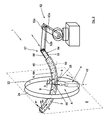
- the FIG. 1 is a front view of the device 1 according to the invention for producing a component which is at least partially formed from fiber composites, from a semifinished product 2, which may be the resulting component in an intermediate stage or a prefabricated part for this purpose.
- the component to be produced can in particular be an aircraft component.
- the semifinished product can be a prefabricated intermediate product or the component that is being formed be.
- the material can be placed on a tool molding or short a molding or a tool shape, such as a positive shape (Mandril), or on an already coated with material tool shape.
- a production of ribs in particular of CFK fuselage frames, an aircraft.
- prepreg fiber composites which are formed from a resin mixture, while maintaining a defined fiber volume content
- a soaked reinforcing fibers are used.
- the strength of the fiber composite material is determined essentially by the reinforcing fibers. In this way, the fiber volume fraction for a weight-optimized component can be selected to be relatively high.
- a preimpregnated fiber bundle or a fiber strand (roving), in particular a CFRP roving, can be used for coating the tool mold or the component.
- the apparatus 1 comprises one or more generally a dispenser 4 or applicator head 4 suitable for receiving and dispensing a predetermined maximum amount of material for the manufacture of the component.
- the dispenser 4 may comprise or consist of a spool for receiving and dispensing the material.
- the dispensing device may in particular comprise a housing in which the material is received, for example by means of the coil, and an opening provided therein for the passage of the material from the interior of the housing to the outside.
- the dispensing device may have a delivery device with which the delivery of the material can be influenced or controlled.
- the feeding device may include a motor with which the material can be dispensed or unwound from a spool.
- the motor When using a coil, the motor may drive the coil to receive material on the coil and / or to dispense from the coil.
- the engine may be in communication with a control device of the manufacturing device.
- the delivery device may include spring means for releasing the material against a biasing force.
- the dispensing device 4 may comprise at least one application device 44, for example a job roll for pressing or winding the composite strip 6 on or on the working surface 8 of the tool mold 10.
- the composite strip 6 is arranged on a within a housing 46 of the dispensing device 4 Roll, not shown, and is provided via this the applicator 44.
- the material for the use of the manufacturing apparatus according to the invention or the manufacturing method according to the invention is basically any layer material and in particular any band-shaped material into consideration.
- the material is a composite tape 6 (slit tape), i. a band made of a composite material.
- a unidirectional CFRP prepreg tape (UD-CFRP prepreg tape) suitable for producing high-strength structures can be used as composite strip 6.
- the material is placed in a defined manner on a working surface 8 of a tool mold 10 or a semifinished product 2.
- the material may be e.g. be placed on this or on this with a predetermined band path or a predetermined angle to the longitudinal direction of the mold or the semi-finished product.
- the material 6 can be placed on a mold, which is formed as a positive mold 10 (Mandril; winding mandrel).
- the tool mold 10 may have a substantially rectangular cross-section with four side surfaces 12, 14, 16, 18 forming a common working surface 8 which may be completely or partially coated with the material 6.
- several layers of the material 6 can be placed on the tool mold 10.
- the manufacturing device 1 has a guide track 22 for guiding a carriage 20. Since on the carriage 20, the dispensing device or the applicator head 4 is arranged, can with the Movement of the carriage 20 on the track 22, the dispensing device relative to the respective working surface 8 are moved.
- the dispenser 4 is rotatably mounted on the carriage 20.
- the axis of rotation of the dispensing device 4 can be fixed, that is rigid, or variable. In the latter case, the axis of rotation can thus be pivoted.
- the change in the axis of rotation can be done manually or with a controlled by a control device actuating device.
- the angle at which the material or the material strip is placed on the tool mold influenced and fixed, pivotable along a to the movement path, preferably in the direction of the working surface, employed pivot axis.
- the applicator head can be moved in a defined working position along the movement path or optionally rotated during a revolution along the movement path about the pivot axis, for example to form a spiral coating.
- the movement path is designed as a circular curved path, so that the section of the tool mold or component to be machined is located in the region of a center, preferably a center, of the movement path.
- the composite material For application of the composite material at an angle of 0 ° with respect to the longitudinal axis of the tool shape or the component of the carriage, for example, along the movement path in a region of the working surface of the mold or the component to be coated movable and the applicator head about the pivot axis in a working position, in which the composite material has an angle of 0 ° with respect to the longitudinal axis of the tool mold or the component.
- the applicator head is pivotable about the pivot axis into a working position in which the composite material at an angle in the range of more than 0 ° to about 90 °, preferably ⁇ 45 °, ⁇ 60 ° and / or 90 ° with respect to a longitudinal axis of the mold or the component can be applied to this.
- At least one application head for parallel application of at least one composite material, in particular a composite material band, can be provided for each work surface.
- applicator heads can be used by means of which multiple composite strip or strands are simultaneously applied to the mold or component.
- the angles of the individual composite strip bands or strands can be adjusted independently of one another, so that a spread in the direction of the larger radius of curvature is avoided in the case of curved tool shapes or components.
- the width of the composite tapes may be different when using applicator heads with multiple composite tapes, multiple applicator heads and / or carrier rings to further improve process efficiency.
- the guideway 22 may be formed as a closed path or as an open path or as a guideway section.
- the guideway 22 may in particular, as in the in the FIG. 1 illustrated embodiment, be designed as a circular path. To support the guideway 22, this may be arranged on a support member 24 or formed integrally therewith.
- the support member may be partially annular or formed as a closed ring and thereby each formed a total of annular.
- the guideway is curved to form a variable or constant curvature radius KR over the longitudinal extent thereof.
- the guideway is designed such that the carriage 20 can be moved on the inside of the guideway.
- the guideway may be formed curvilinear.
- the radius of curvature of the curved path at least partially corresponds to the curvature of the tool shape or the component.
- Tool molds or components which have a curvature profile with a plurality of radii of curvature can also be produced according to the invention.
- the guideway 22 and / or the carrier part are preferably located relative to the workpiece mold in such a way that the longitudinal extent of the guideway extends transversely to the longitudinal extent of an elongated workpiece shape, so that the guideway at least distances the tool mold 10 partially surrounds or surrounds.
- the support member 24 may be supported by a frame 30.
- a plurality of carrier rings along the longitudinal axis of the mold or the component can be arranged one behind the other, characterized in that in particular different angles of Verbundtechnikstoffb selected- or strands can be applied in one operation.
- the tool mold 10 may be positioned so as to be stationary or controlled relative to the support ring 24 in a relative movement between the guide track and the tool mold or the semi-finished, that the side surfaces 12, 16 of the mold or semi-finished parallel to the vertical axis 26 of the support ring 24 extend , Furthermore, the relative movement between the guide track and the tool mold or the semi-finished product can be mechanically adjusted or controlled such that the area of the surface on which the material 6 is placed at a given time in the region of a center M of the carrier ring 24, ie with a deviation of 10% of the radius of curvature KR, is arranged.
- the support ring has at least one running rail for receiving a roller assembly 32 of the carriage.
- the carriage 20 can be driven by the rollers.
- the support ring may have at least one toothed section, which can be brought into engagement with at least one drive wheel of the carriage.
- the drive wheel is, for example, as engaging in a rack of the support member gear educated.
- other drive systems can be used to move the carriage along the path of travel.
- the guideway includes a track rail, not shown, for receiving a roller assembly 32 of the carriage 20 and a schematically indicated gear portion 34 which engages with a drive wheel of the carriage 20, not shown.
- the toothing section 34 extends along the entire movement path 22.
- the drive wheel can be designed, for example, as a toothed wheel, which engages in a toothed rack of the carrier ring 24.
- the roller assembly 32 has two roller pairs 36, 38 spaced apart along the path of movement 22.
- the dispensing device 4 With a rotatability of the dispensing device 4 for adjusting the course of the longitudinal direction of the laid-up material 6, this is for the application of the material 6 rotatable about an employee employed to the movement path 22 in the direction of the mold 10 pivot axis 40.
- the tool shape or the component can be arranged such that the pivot axis 40 extends in the illustrated embodiment of the device at an angle of about 90 ° to an applied to the radius of curvature R of the trajectory 22 tangent 42 and through the center M of the circular path extends.
- the inventive device 1 is due to the along the working surface 8 encompassing trajectory 22 movable carriage 20, the pivotable dispensing device 4 and the feed movement between the mold 10 and trajectory 22 in the position, the curved mold 10 for the production of CFRP fuselage frames Device technology easy to coat.
- the application of the composite strip 6 on the work surface 8 can be flat, partial or according to other programmable patterns.
- the layer sequence and number of applied composite bands can be adjusted depending on the application.
- the composite material band 6 can be applied with different band angles with respect to the longitudinal axis of the tool mold 10.
- any intermediate angle and angle curves are adjustable. This will be explained in more detail below with reference to exemplary working positions A, B, C of the delivery device 4.
- the device according to the invention is thus able, in particular, to simply coat a curved tool shape or a curved component as well as other complex component geometries, characterized in that the term component in the context of the invention also means, in particular, a part of a component or a semifinished product. Due to the flexible angular orientation and the ability to apply local reinforcements, a weight reduction of the components is achieved with high strength.
- the sequence of layers and the number of layers applied can be varied depending on the application.
- the fiber flow can be adapted to the load path of the component, so that the production of lightweight, high-strength structures is possible.
- the composite may be applied to the work surface at an angle of about 0 °, ⁇ 45 °, ⁇ 60 °, and / or 90 ° with respect to the longitudinal axis of the tool mold or the longitudinal axis of the component.
- any intermediate angle and angle curves are adjustable by means of the device according to the invention.
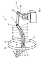
- FIG. 2 the a spatial representation of the device 1 from FIG. 1 shows, the composite strip 6 in the illustrated operating position A of the dispensing device 4 with a band angle ⁇ of 90 ° with respect to a longitudinal axis 48 of the mold 10 on the working surface 8 can be applied.
- the dispensing device 4 is pivoted about the pivot axis 40 in the working position A, in which the composite strip 6 is applied with the desired band angle ⁇ of 90 ° with respect to the longitudinal axis 48 on the tool mold 10 or on already applied strip material.
- An end portion 50 of the composite tape 6 is placed on the work surface 8 of the tool mold 10 and the dispenser 4 spaced from the work surface 8 by means of the in FIG. 2 not shown carriage 20 (see FIG.
- the band 6 is separated and the tool mold 10 relative to the movement path 22 corresponding to the amount of Bandwidth b procedure. This process is repeated until the desired region of the mold 10 is provided with a defined layer structure. Subsequently, interposed or preceded by this process, the composite strip 6 can be applied with other strip angles. For more efficient coating, the 90 ° band angle is reduced by an angular deviation that depends on the circumference of the tool mold 10 and the bandwidth b. This allows a continuous, spiral-shaped coating of the mold 10 in one operation. Depending on the rotational speed of the carriage 20 (see FIG. 1 ) along the movement path 22 and the feed speed of the tool mold 10, the band angle ⁇ can be set differently.
- the feed device is provided for carrying out a feed movement of the tool mold 10 or of the semifinished product 2 relative to the guide track 22 and has a coupling device for holding or fastening a section or an end section 54 of the tool mold 10 or the semifinished product 2.
- the feed device may comprise an actuator arm or robot arm 52 with the coupling device or a carriage 60 movable on a feed track 62 with the coupling device.
- the actuating arm or the robot arm 52 or the carriage 62 is moved by an adjusting mechanism or a guide device which is part of the feed device or is assigned to the feed device and is functionally connected thereto.
- the adjusting mechanism may in particular have the drive device for actuating the feed device.
- the guide device may have the functions for controlling, regulating the operation of the feed device or the adjusting mechanism.
- the adjusting mechanism or the guide device may in particular be part of a movement control.
- the motion control may control functions for the three-dimensional movement of the actuator arm or the robot arm 52 and the movement of the carriage 20 along the movement path 22 and / or the dispensing device 4 along the pivot axis 40 and / or the mold 10 or the semifinished product 2 and / or the Trajectory 22 each relative to each other.
- the coupling device of the delivery device with a combination of a feed track 62 with a movable on this carriage 60 or an actuator arm or robot arm 52 have a coupling device with which on the carriage 60 and the actuator arm or robot arm 52 and in particular An end portion 54 of the tool mold 10 or the semifinished product 2 can be fastened to one end section of the carriage 60 or arm 52.
- the tool mold 10 or the semifinished product 2 can be moved relative to the movement path 22 and / or the delivery device 4.
- the coupling device of the carriage 60 or of the positioning arm or robot arm 52 can be designed for fastening the tool mold 10 or the semifinished product 2 so that it can surround the tool mold 10 or the semi-finished product 2 and in particular an end section thereof at least in sections.
- other fastening means may be provided.
- the coupling device may be designed in such a way that it receives in particular a form-fitting manner an end section of the tool mold 10 or the semifinished product 2.
- the feed device can in particular have an actuating arm or robot arm 52 ( Figures 2 and 3 ), which is arranged outside the guide track 22 or the carrier ring 24 and which is connected to the tool mold, for example, such that it engages around an end portion 54 of the tool mold 10 in sections with a gripper 56.
- the adjusting arm 52 may in particular be formed from a first arm 52a and a second arm 52b, which is coupled to the first arm 52a by means of a joint 52c and on which the coupling device 57 is arranged.
- the tool shape or the semifinished product 10 is curved in the region of the frame in accordance with the cross section of the fuselage, so that it has an arcuate longitudinal axis 48.
- the semifinished product When using a semi-finished product without one Mold or when attaching the semifinished product to the coupling device, the semifinished product has been brought to this example by sewing or pre-curing in a dimensionally stable state.
- this or this can be moved relative to the movement path 22 along a curved path (feed path) by means of the arm 52 or the carriage 60.
- This curved path can be provided in such a way that it can be described in three dimensions. In particular, this can be located in a plane.
- the center line of the semifinished product or the mold is located in a plane, it can be provided that the curved path is also located in a plane.
- the connecting line of the centroids of the respective smallest cross sections along the longitudinal direction of the semifinished product or the tool mold can be used as center line.
- the curvature with the generally location-dependent radius of curvature RK which comprises the completed by the arm 52 or the end portion or the carriage 60 by the motion control or movement cam track
- the curvature or the radius of curvature R of the mold 10 in Reference to the longitudinal axis 48 or center line corresponds or retraces.
- a deviation of 10% with respect to the length of the semifinished product or the mold can be allowed.
- the tool mold 10 may further be positioned to the support ring 24 such that a tangent 58 at an angle of 90 degrees ⁇ 15 degrees, and more preferably ⁇ 5 degrees, to one of the machined portion 28 of the tool mold 10 is applied to the arc of curvature thereof relevant section of the guideway 22 spanned plane E runs.
- the device 1 is a control device, not shown, in particular with a CNC control assigned to the movement control of the carriage 20 along the movement path 22 and / or the delivery of the material from the dispensing device 4 and / or the rotation of the dispensing device 4 and / or If appropriate, the change of the pivot axis and / or the feed movement of the tool mold 10 or the semifinished product 2 relative to the movement path 22 is particularly advantageous if the movement of the carriage 20 along the movement path 22 and the Delivery movement of the mold 10 and the semifinished product 2 in dependence on each other.
- the feed movement of the tool mold 10 or of the semifinished product 2 can be effected, for example, synchronously with the movement of the carriage 20 and / or with a defined over or under reduction ratio to the band angle ⁇ (the angle between the longitudinal direction of the material when placing it on the surface 8 and the tangent to the central longitudinal axis of the tool mold 10 or the semi-finished product at the point where the material is currently placed on the surface 8, and seen in the tangential plane of the surface 8).
- the carrier ring 24 is moved relative to the tool mold 10.
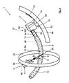
- FIG. 3 shows a spatial representation of the device 1 from FIG. 1 in which the dispensing device 4 is in a working position B according to which the composite strip 6 is applied to the working surface 8 at a band angle ⁇ of approximately 0 ° with respect to the longitudinal axis 48 of the tool mold 10.
- the dispensing device 4 is moved along the movement path 22 formed on the carrier ring 24 into a region of the working surface 8 of the tool mold 10 to be coated and around the pivot axis 40 in FIG pivoted the 0 ° working position B, in which the composite strip 6 with a band angle ⁇ of 0 ° with respect to the longitudinal axis 48 of the mold 10 can be applied to this.
- the end portion 50 of the composite tape 6 is placed on the work surface 8 by the applicator 44.
- the tool mold 10 is moved by means of the robot arm 52 along the curvature radius R of the tool mold 10 corresponding cam track relative to the movement path 22, characterized in that the composite strip 6 is placed on the working surface 8 by means of the dispensing device 4 (fiber laying).
- the dispenser 4 maintains its position on the carrier ring 24 while the tool mold 10 is moved relative to the carrier ring 24.
- the delivery device 4 is moved from the illustrated 9 o'clock position along the movement path 22 into a 6 o'clock or 12 o'clock position and subsequently into a 3 o'clock position.
- at least one dispensing device 4 can be provided for each side face, characterized in that the coating of the side faces can take place at the same time.
- the bandwidth b of at least one dispensing device 4 can also be selected such that the side surfaces 12, 14, 16, 18 are completely covered with the composite strip 6 in one operation at a time.
- the carrier ring 24 is moved relative to the tool mold 10.
- a composite material designed as a composite strip can be applied according to the solution according to the invention with different strip angles with respect to a longitudinal axis of the tool shape or of the component.
- FIG. 4 a spatial representation of a device 1 with a working position C of the dispensing device 4 is shown, in which the composite strip 6 with a Band angle ⁇ of 45 ° with respect to the longitudinal axis 48 of the tool mold 10 is applied to the working surface 8.
- the dispensing device 4 is rotated about the pivot axis 40 in a 45 ° position.
- the tool mold 10 is moved according to the radius of curvature R of the tool mold 10 relative to the movement path 22 and the dispensing device 4 along the movement path 22, characterized in that the composite strip 6 is wound around the tool mold 10 by means of the dispenser 4.
- the tool mold 10 is guided by a feed carriage 60 which is movable along a feed track 62, the mold or the semi-finished or the same end of the same by means of the coupling device can be attached to the delivery carriage 60.
- the coupling device can have a gripper 64, with which a section or an end section 54 of the tool mold 10 can be encompassed at least in sections.
- the feed path 62 is formed in this variant as a curved path on a support member 66.
- the radius of curvature RZ of the feed track 62 may in particular correspond to the radius of curvature R of the tool mold 10.
- the tool mold 10 is positioned such that the portion 28 of the tool mold 10 to be machined is located in the region of the center of the carrier ring 24.
- the support member 66 has a running rail, not shown, for receiving a roller assembly 68 of the Zustellwagens 60 and has a schematically indicated toothing portion 70 which is in engagement with a not illustrated drive wheel of the Zustellwagens 60.
- the toothing section The roller arrangement 68 has two roller pairs 72, 74 spaced apart from one another along the feed track 62.
- the drive wheel may be designed, for example, as a toothed wheel which engages in a toothed rack of the carrier part 66.
- the carrier ring it is possible to arrange more than one application head along the movement path of the carrier ring.
- at least one pair of applicator heads displaceable by an angle of approximately 180 ° relative to one another on the movement path can be provided.
- An advantage of a 180 ° offset from each other arrangement of the application heads is the compensation of the pressure forces on the mold or the component.
- a complete coverage of the tool mold or the component can be achieved with a single operation with reduced weight of the device.
- the application heads can also be moved independently of each other, characterized in that it is advantageous if the control of the application heads is based on a common time base.
- the device for producing ribs, in particular CFRP fuselage ribs, or fuselage segments of an aircraft has proved to be particularly advantageous.
- the web and flange height and the thickness of the layer structure may be variable or constant along the longitudinal extent of the component.
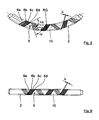
- FIGS. 5 and 6 showing an individual representation of the partially coated tool mold 10 FIG. 4 show in a side view and a plan view
- a plurality of application heads 4 can be used to improve the process efficiency, by means of which at the same time a plurality of composite bands 6 are applied to the work surface 8.
- four composite bands 6a, 6b, 6c, 6d were applied simultaneously.
- the band angles of the individual composite bands 6a, 6b, 6c, 6d can be adjusted independently of each other, so that the occurring in curved molds 10, in FIG. 5 shown band spread in the direction of the larger radius of curvature RG of the tool mold 10 is avoided.
- the widths b of the composite tapes 6a, 6b, 6c, 6d may be different when using applicator heads 4 with multiple composite tapes to further improve process efficiency.
- the bulkhead may have a C-shaped cross-section and be formed in one piece.
- the frame can have several sub-profiles, such as an L and a C-profile.
- a frame with E-shaped cross section can be produced.
- two cores are preferably used, which are coated separately and then together in a first step.
- two cores are preferably used, which are likewise coated separately and then together in a first working step.
- a leg of the profile is bent by means of a thermoforming process at an angle of for example 90 ° to the profile web.
- the angle between the web and the flange may be greater or less than 90 ° for all cross-sectional variants in order to ensure a flush connection of the flange to a curved surface of the aircraft fuselage.
- Stepped recesses of the flanges for the attachment limbs of the aircraft longitudinal stiffeners can already be provided during the production of the frames or, for example after the penetration of the penetrations for the aircraft longitudinal stiffeners, are formed by means of a thermoforming method.
- the tool mold has at least one pair of groove-shaped recesses arranged diametrically opposite one another, each extending parallel to a longitudinal axis of the tool mold.
- the groove-shaped recesses serve as an outlet for the separating blade of a separating device which is used to separate the fiber composite structure into two or four profiles.
- the created fiber composite structure may be separated into two approximately C-shaped or four L-shaped profiles which may be used as frames or parts of a frame. The separation of the composite structure can be done before or after curing.
- the component is preferably after the separation process in a negative mold, optionally additionally with a core, for example, a part of the then multi-part mold, inserted and cured.
- a separation after curing the unseparated component, possibly inserted in a negative mold, is evacuated together with the mold and cured in an autoclave. Subsequently, the cured component is separated and removed from the mold.
- a composite material with a defined angle is applied to at least one working surface of a tool mold or a component by means of at least one application head, characterized in that the application head via at least one carriage along a work surface at least partially encompassing movement path is moved relative to the work surface.
- the application head is pivoted, in particular rotated, along a pivot axis which is set towards the movement path.
- the tool mold or the component and the movement path are preferably moved relative to each other for applying the composite material to the work surface.
- the composite strip is preferably applied to the work surface in accordance with the component contour to be produced.
- the tool mold 10 has two diametrically arranged approximately U-shaped recesses 76, 78, which are introduced into the side surfaces 14, 18 of the mold 10 and each parallel to the longitudinal axis 48 (see FIG. 2 ) of the tool mold 10.
- the groove-shaped recesses 76, 78 serve as an outlet for the separating blade of a separating device, not shown, which is used to separate the fiber composite material structure 2.
- the created fiber composite structure 2 can be separated in the mold 10 with approximately rectangular cross section, for example, in two C-shaped profiles 80, which are used for CFRP frames of an aircraft.
- the C-frames 80 each have two flanges 82, 84, which are connected by a web 86, characterized in that the angle between the upper and lower flange and the web is in each case about 90 °.
- the web and flange height and the thickness of the layer structure can be variable or constant along the longitudinal extension of the frames 80.
- the separation of the composite component 2 can take place before or after curing. If the separation takes place before curing, the component 2 is preferably inserted into a negative mold, optionally additionally with a core, after the separation process and cured. In a separation after curing, the unseparated component, possibly inserted in an additional negative mold, evacuated together with the mold and cured in an autoclave. Subsequently, the cured component is separated and removed from the mold.
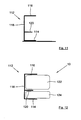
- FIG. 8 shows an individual view of a CFK hull rib 88 with an approximately C-shaped cross-section according to another embodiment.
- the bulkhead 88 has two flanges 90, 92 which are connected by a web 94, characterized in that the angle between the upper flange 90 and the web 94 about 90 ° and the angle between the lower flange 92 and the web 94 approximately 110 °, to ensure a flat connection of the flange 92, for example, to the curved surface 96 of an aircraft fuselage.
- the rib 98 can have a plurality of partial profiles, such as, for example, an L and a C Profile 106, 108 have.
- the C-profiles 106 are, for example, according to the description of FIG. 7 produced.
- a preferred tooling for producing the L-shaped profiles 108 will be described below FIG. 10 explained in more detail.
- the mold 10 has according to FIG. 10 two pairs of diametrically arranged, approximately U-shaped recesses 110, which are parallel to the longitudinal axis 48 (see FIG. 2 ) of the tool mold 10 in the region of the side surfaces 12, 14, 16, 18 extend.
- the groove-shaped recesses 110 are used, as already explained, as an outlet for the separating blade of a separating device, not shown, which is used to separate the fiber composite component 2.
- the four curved L-profiles 106 can be removed from the tool mold 10.
- FIG. 11 shows an embodiment of a CFK hull rib 112 with an approximately E-shaped cross-section.
- the integrally formed bulkhead 112 has two flanges 114, 116, which are connected by means of a web 118, characterized in that between the flanges 114, 116, a stiffening rib 120 is arranged.
- the stiffening rib 120 extends parallel to the flanges 114, 116, characterized in that the angle between the lower and upper flange 114, 116 and the web 118 and the angle between the stiffening rib 120 and the web in the illustrated embodiment about 90 ° is.
- the CFK hull frame 112 out FIG. 11 with tool mold 10 shows, characterized in that only one component half is shown, find its manufacture two cores 122, 124 use, which are coated individually and then together in a first step.
- the upper core 122 has a opposite the lower core 124 enlarged cross-sectional area, so that the distance between the flange 116 and the reinforcing rib 120 is increased relative to the distance of the flange 114 to the reinforcing rib 120.
- one-piece frames 126 with LCF cross section are according to FIG. 14 showing the CFK-hull bulkhead 126 with tool mold 10, characterized in that only one half of the component is shown, also two cores 128, 130 are used, which are coated separately and then together in a first step.
- the leg portion 100 of the profile 126 is bent by means of a thermoforming method - as indicated by an arrow - at an angle of for example 90 ° to the flange 100.
- Stepped recesses (not shown) of the flanges 92, 100, 114, for fastening limbs of aircraft longitudinal stiffeners, so-called stingers, can already be provided during the production of the frames 80, 88, 98, 112, 126 or, for example after the introduction of the not shown Breakthroughs for the stringers are formed by a thermoforming process.
- the device according to the invention is not limited to the described embodiment with only one dispensing device 4, but a plurality of applicator heads 4 can be movably arranged along the movement path 22 of the carrier ring 24 in order to further optimize the process speed.
- the application heads 4 can be moved independently of each other, characterized in that it is advantageous if their control is based on a common time base. For example, two offset by an angle of about 180 ° to each other on the movement path 22 movable applicator heads 4 are provided.
- the compensation of the pressure forces on the tool mold 10 or the component 2 is advantageous in the case of an arrangement of the application heads 4 that is staggered by 180.degree ..
- the invention is not limited to the embodiment shown with only one carrier ring 24, for example several carrier rings 24 can be serially connected be arranged one behind the other, wherein it can be provided that in particular composite bands 6 with different band angles in one Operation can be applied.
- the invention is also not limited to curved tool molds 10 or components 2.
- a tool mold having a substantially rectangular cross section preferably all four side surfaces of the tool mold are occupied, characterized in that the application head is moved in each case by 90 ° along the movement path.
- the applicator head is pivoted along the trajectory to a 3, 6, 9, and 12 o'clock position.
- at least one application head can be provided for each work surface, characterized in that the coating of the side surfaces takes place at the same time.
- a layer structure with an angle of more than 0 ° to about 90 °, preferably ⁇ 45 °, ⁇ 60 ° and / or 90 ° with respect to the longitudinal axis of the mold or the component of the applicator head is pivoted about the pivot axis in a working position, in which is applied to the composite with the desired angle to the working surface, characterized in that the tool shape or the component is moved relative to the movement path and the carriage along the movement path (fiber winding).
- the angle can be set differently.
- the applicator head is rotated to a 90 ° position, an end portion of the composite tape is pressed onto the work surface and the applicator head is rotated 360 ° along the path of travel by the carriage, characterized in that a composite strip is applied to the composite web Tool mold is applied. Subsequently, the tape is separated and the tool shape or the component along the feed path according to the amount of a bandwidth proceed.
- the 90 ° angle is reduced or increased by a deviation that depends on the circumference of the mold or component and the bandwidth.
- the angle of the following layer of the composite material can be correspondingly increased or decreased by a deviation, so that the material properties are balanced. This allows a continuous, spiral-shaped coating of the mold or the component.
- a carrier ring having the movement path is moved relative to the tool shape or the component.
Landscapes
- Engineering & Computer Science (AREA)
- Mechanical Engineering (AREA)
- Chemical & Material Sciences (AREA)
- Composite Materials (AREA)
- Physics & Mathematics (AREA)
- Nonlinear Science (AREA)
- Robotics (AREA)
- Moulding By Coating Moulds (AREA)
- Reinforced Plastic Materials (AREA)
- Laminated Bodies (AREA)
- Nonwoven Fabrics (AREA)
Applications Claiming Priority (3)
| Application Number | Priority Date | Filing Date | Title |
|---|---|---|---|
| US98826707P | 2007-11-15 | 2007-11-15 | |
| DE102007054645A DE102007054645A1 (de) | 2007-11-15 | 2007-11-15 | Vorrichtung und Verfahren zur Herstellung eines Faserverbundwerkstoff-Bauteils |
| PCT/EP2008/009713 WO2009062749A1 (de) | 2007-11-15 | 2008-11-17 | Vorrichtung und verfahren zur herstellung eines faserverbundwerkstoff-bauteils |
Publications (2)
| Publication Number | Publication Date |
|---|---|
| EP2225092A1 EP2225092A1 (de) | 2010-09-08 |
| EP2225092B1 true EP2225092B1 (de) | 2012-03-28 |
Family
ID=40576774
Family Applications (1)
| Application Number | Title | Priority Date | Filing Date |
|---|---|---|---|
| EP08850878A Not-in-force EP2225092B1 (de) | 2007-11-15 | 2008-11-17 | Vorrichtung und verfahren zur herstellung eines faserverbundwerkstoff-bauteils |
Country Status (10)
| Country | Link |
|---|---|
| US (1) | US8394222B2 (ru) |
| EP (1) | EP2225092B1 (ru) |
| JP (1) | JP2011502831A (ru) |
| CN (1) | CN101861242B (ru) |
| AT (1) | ATE551175T1 (ru) |
| BR (1) | BRPI0819329A2 (ru) |
| CA (1) | CA2705816A1 (ru) |
| DE (1) | DE102007054645A1 (ru) |
| RU (1) | RU2505404C2 (ru) |
| WO (1) | WO2009062749A1 (ru) |
Families Citing this family (57)
| Publication number | Priority date | Publication date | Assignee | Title |
|---|---|---|---|---|
| JP4263752B2 (ja) * | 2007-08-10 | 2009-05-13 | トヨタ自動車株式会社 | 繊維強化樹脂部材とその製造方法、および繊維織物の製造装置 |
| NL2004191C2 (en) | 2010-02-04 | 2011-08-08 | Protension Composites | Device and method for producing a fiber composite product. |
| US8758538B2 (en) * | 2010-05-12 | 2014-06-24 | Fives Machining Systems, Inc. | Robotic based fiber placement cell with stationary dispensing head and creel |
| JP5510179B2 (ja) * | 2010-08-18 | 2014-06-04 | 豊田合成株式会社 | フィラメントワインディング装置 |
| DE102010039955A1 (de) * | 2010-08-30 | 2012-03-01 | Deutsches Zentrum für Luft- und Raumfahrt e.V. | Fertigungsanlage zur Herstellung von Faserverbundmaterial-Bauteilen |
| DE102010053635B4 (de) * | 2010-12-07 | 2017-05-11 | Hero Gmbh | Verfahren zur Herstellung eines Faserverbundprodukts |
| US20120152432A1 (en) * | 2010-12-15 | 2012-06-21 | Samuel Francis Pedigo | Methods and systems for fiber placement using a stationary dispenser |
| FR2969666B1 (fr) * | 2010-12-24 | 2013-02-01 | Messier Dowty Sa | Procede de tressage de fibres renforcantes a variation d'inclinaison des fibres tressees |
| JP5697506B2 (ja) * | 2011-03-25 | 2015-04-08 | シキボウ株式会社 | ドライプリフォーム、複合材料からなる環状構造体、及びその製造方法 |
| DE102011007235A1 (de) | 2011-04-12 | 2012-10-18 | Airbus Operations Gmbh | Verfahren und Vorrichtung zur Herstellung eines Faserverbundbauteils und Faserverbundbauteil |
| CN103085165A (zh) * | 2011-11-04 | 2013-05-08 | 余赞阳 | 一种石膏装饰线条自动生产线 |
| CN102941676A (zh) * | 2012-10-19 | 2013-02-27 | 湖北三江航天红阳机电有限公司 | 一种旋转体双层复合材料缠绕成型方法 |
| CN105121138B (zh) * | 2013-02-08 | 2018-04-24 | Lm Wp 专利控股有限公司 | 用于制造物品的系统和方法 |
| CN105579221B (zh) * | 2013-03-12 | 2018-06-08 | 迪芬巴赫机械工程有限公司 | 用于制造先进复合部件的方法和系统 |
| US10863794B2 (en) | 2013-06-25 | 2020-12-15 | Nike, Inc. | Article of footwear having multiple braided structures |
| EP2978332B1 (en) | 2013-06-25 | 2018-12-05 | NIKE Innovate C.V. | Article of footwear with braided upper |
| EP3060693B1 (en) * | 2013-10-25 | 2018-06-27 | United Technologies Corporation | Plasma spraying system with adjustable coating medium nozzle |
| US10006156B2 (en) | 2014-03-21 | 2018-06-26 | Goodrich Corporation | Systems and methods for calculated tow fiber angle |
| US9623611B2 (en) | 2014-03-21 | 2017-04-18 | Ingersoll Machine Tools, Inc. | Flexible fiber placement system for small composite parts manufacturing and methods |
| CN104570955B (zh) * | 2014-11-24 | 2018-06-22 | 中国科学院自动化研究所 | 一种复合材料自动铺丝机控制系统及控制方法 |
| US9839253B2 (en) | 2014-12-10 | 2017-12-12 | Nike, Inc. | Last system for braiding footwear |
| US9668544B2 (en) | 2014-12-10 | 2017-06-06 | Nike, Inc. | Last system for articles with braided components |
| US10674791B2 (en) | 2014-12-10 | 2020-06-09 | Nike, Inc. | Braided article with internal midsole structure |
| CZ2015275A3 (cs) * | 2015-04-24 | 2016-06-22 | Magna Exteriors & Interiors (Bohemia) S.R.O. | Zařízení pro ovíjení rámů vlákennými rovingy |
| US20160345675A1 (en) | 2015-05-26 | 2016-12-01 | Nike, Inc. | Hybrid Braided Article |
| US10238176B2 (en) | 2015-05-26 | 2019-03-26 | Nike, Inc. | Braiding machine and method of forming a braided article using such braiding machine |
| US10060057B2 (en) | 2015-05-26 | 2018-08-28 | Nike, Inc. | Braiding machine with non-circular geometry |
| US10555581B2 (en) | 2015-05-26 | 2020-02-11 | Nike, Inc. | Braided upper with multiple materials |
| US10280538B2 (en) | 2015-05-26 | 2019-05-07 | Nike, Inc. | Braiding machine and method of forming an article incorporating a moving object |
| US11103028B2 (en) | 2015-08-07 | 2021-08-31 | Nike, Inc. | Multi-layered braided article and method of making |
| US9920462B2 (en) | 2015-08-07 | 2018-03-20 | Nike, Inc. | Braiding machine with multiple rings of spools |
| DE102015117434B3 (de) * | 2015-10-13 | 2017-02-02 | Oke Group Gmbh | Inlineverfahren zur Herstellung eines Federleistenprofils für einen Lattenrost |
| DE102015119682A1 (de) * | 2015-11-13 | 2017-05-18 | Airbus Operations Gmbh | Flechtklöppel sowie Flechtvorrichtung |
| EP3173217B1 (de) | 2015-11-24 | 2022-08-24 | Airbus Defence and Space GmbH | Vorrichtung und verfahren zum herstellen eines faserverbundbauteils |
| EP3173218B1 (de) * | 2015-11-24 | 2020-11-11 | Airbus Defence and Space GmbH | Vorrichtung und verfahren zum herstellen eines faserverbundbauteils |
| US10155367B2 (en) * | 2015-12-29 | 2018-12-18 | The Boeing Company | Coordinated composite tape laying |
| DE102016203073A1 (de) * | 2016-02-26 | 2017-08-31 | Airbus Defence and Space GmbH | Werkzeugsystem und Verfahren zur Herstellung eines Faserverbundhalbzeugs sowie Verfahren zur Herstellung eines Faserverbundbauteils |
| FR3055575B1 (fr) | 2016-09-07 | 2019-10-18 | Safran Aircraft Engines | Installation et procede pour la formation d'une preforme fibreuse de revolution presentant en section radiale un profil evolutif |
| FR3062336B1 (fr) * | 2017-02-02 | 2019-04-12 | Safran Ceramics | Procede de fabrication d'une piece en materiau composite |
| CN108790214A (zh) * | 2017-04-27 | 2018-11-13 | 谢雄军 | 一种使用纤维缠绕一次成型头盔盔体的工艺方法 |
| US11202483B2 (en) | 2017-05-31 | 2021-12-21 | Nike, Inc. | Braided articles and methods for their manufacture |
| US11051573B2 (en) | 2017-05-31 | 2021-07-06 | Nike, Inc. | Braided articles and methods for their manufacture |
| US10806210B2 (en) | 2017-05-31 | 2020-10-20 | Nike, Inc. | Braided articles and methods for their manufacture |
| DE102017222579A1 (de) * | 2017-12-13 | 2019-06-13 | Schäfer MWN GmbH | Verfahren zum Herstellen eines Bauelements und Bauelement |
| CN108328436B (zh) * | 2018-04-04 | 2023-07-14 | 洛阳理工学院 | 一种弯管防腐复合带的自动缠绕包覆机 |
| CN108190075A (zh) * | 2018-04-04 | 2018-06-22 | 洛阳理工学院 | 一种弯管缠绕机弯管用滚动支撑车 |
| JP7097003B2 (ja) * | 2018-11-15 | 2022-07-07 | 村田機械株式会社 | フィラメントワインディング装置 |
| DE102019206436A1 (de) * | 2019-05-06 | 2020-11-12 | Schäfer MWN GmbH | Mehrpunktlenker für ein Fahrwerk eines Fahrzeugs |
| DE102019206435A1 (de) * | 2019-05-06 | 2020-11-12 | Schäfer MWN GmbH | Mehrpunktlenker für ein Fahrwerk eines Fahrzeugs |
| CN111037950B (zh) * | 2019-12-11 | 2022-01-21 | 湖北吉利太力飞车有限公司 | 一种曲面成型的连续等厚度铺层方法及成型件和应用 |
| CN111620209B (zh) * | 2020-05-18 | 2022-06-10 | 江苏长实基业电气科技有限公司 | 一种预埋等电位泡沫模具胶带缠绕设备 |
| CN112061867B (zh) * | 2020-08-28 | 2022-05-24 | 绍兴市柯桥区东纺纺织产业创新研究院 | 一种纺织品缠绕设备 |
| CN113086760B (zh) * | 2021-03-24 | 2022-11-01 | 哈尔滨复合材料设备开发有限公司 | 一种纤维复合材料环链缠绕设备及其使用方法 |
| FR3125740B1 (fr) * | 2021-08-02 | 2023-08-11 | Mf Tech | Machine d’enroulement filamentaire avec systeme de deplacement a deux robots |
| DE102021214478A1 (de) | 2021-12-16 | 2023-06-22 | Zf Friedrichshafen Ag | Herstellungsvorrichtung und Verfahren zum Herstellen einer Rotorbandage für einen Rotor |
| CN114536725A (zh) * | 2022-03-14 | 2022-05-27 | 四川慧科合创机械技术有限公司 | 连续纤维增强热塑性复合管管件的制作装置及制作方法 |
| CN117885372B (zh) * | 2024-03-15 | 2024-05-28 | 北京卫星制造厂有限公司 | 一种网格构件缠绕成型的定位调控装置和定位调控方法 |
Family Cites Families (15)
| Publication number | Priority date | Publication date | Assignee | Title |
|---|---|---|---|---|
| US3708131A (en) * | 1966-04-01 | 1973-01-02 | Union Carbide Corp | Method of and apparatus for wrapping layered composite thermal insulation |
| US3727851A (en) * | 1966-06-30 | 1973-04-17 | Airco Inc | Apparatus for winding insulation onto vessels |
| US3397847A (en) * | 1966-08-31 | 1968-08-20 | Herbert V. Thaden | Elbow winding apparatus |
| DE1779172A1 (de) * | 1968-07-15 | 1971-09-16 | Bolenz & Schaefer Maschf | Vorrichtung zum Herstellen von Rohrbogen aus faserverstaerktem Kunstharz |
| FR2082343A5 (en) * | 1970-03-11 | 1971-12-10 | Plastrex Manurhin Sarl | Filament wound pipe elbows prodn - esp of glass reinforced thermoplastics |
| US4323408A (en) * | 1979-09-25 | 1982-04-06 | Ameron, Inc. | Filament winding of plastic articles |
| DE3843488A1 (de) * | 1988-12-23 | 1990-07-05 | Ver Foerderung Inst Kunststoff | Wickelanlage sowie wickelverfahren |
| US5031846A (en) * | 1989-06-29 | 1991-07-16 | Lea Richard H | Filament winding machine |
| IL98381A0 (en) * | 1990-06-25 | 1992-07-15 | Du Pont | Apparatus and method for winding fiber reinforced thermoplastic resin tow and the product thereof |
| DE4122785C2 (de) * | 1991-07-10 | 1994-09-22 | Deutsche Forsch Luft Raumfahrt | Drehbank-Wickelanlage zur Herstellung von Bauelementen aus faserverstärkten Kunststoffen |
| US7282107B2 (en) | 2003-08-22 | 2007-10-16 | The Boeing Company | Multiple head automated composite laminating machine for the fabrication of large barrel section components |
| US7407556B2 (en) | 2004-04-21 | 2008-08-05 | Ingersoll Machine Tools, Inc. | Automated fiber placement using multiple placement heads, replaceable creels, and replaceable placement heads |
| US20060118244A1 (en) | 2004-12-02 | 2006-06-08 | The Boeing Company | Device for laying tape materials for aerospace applications |
| US7300014B2 (en) * | 2005-01-11 | 2007-11-27 | Lotus Designs, Llc | Centerless and openable tool carrier for processing of complex shapes |
| RU2287430C1 (ru) * | 2005-05-16 | 2006-11-20 | Государственное образовательное учреждение высшего профессионального образования Восточно-Сибирский государственный технологический университет | Способ адаптивного управления процессом намотки и устройство для его осуществления |
-
2007
- 2007-11-15 DE DE102007054645A patent/DE102007054645A1/de not_active Ceased
-
2008
- 2008-11-17 BR BRPI0819329A patent/BRPI0819329A2/pt not_active IP Right Cessation
- 2008-11-17 US US12/742,443 patent/US8394222B2/en not_active Expired - Fee Related
- 2008-11-17 CA CA2705816A patent/CA2705816A1/en not_active Abandoned
- 2008-11-17 JP JP2010533508A patent/JP2011502831A/ja not_active Withdrawn
- 2008-11-17 WO PCT/EP2008/009713 patent/WO2009062749A1/de active Application Filing
- 2008-11-17 AT AT08850878T patent/ATE551175T1/de active
- 2008-11-17 EP EP08850878A patent/EP2225092B1/de not_active Not-in-force
- 2008-11-17 RU RU2010123986/05A patent/RU2505404C2/ru not_active IP Right Cessation
- 2008-11-17 CN CN2008801169024A patent/CN101861242B/zh not_active Expired - Fee Related
Also Published As
| Publication number | Publication date |
|---|---|
| EP2225092A1 (de) | 2010-09-08 |
| WO2009062749A1 (de) | 2009-05-22 |
| DE102007054645A1 (de) | 2009-05-28 |
| US8394222B2 (en) | 2013-03-12 |
| CN101861242B (zh) | 2013-07-17 |
| JP2011502831A (ja) | 2011-01-27 |
| BRPI0819329A2 (pt) | 2017-07-25 |
| ATE551175T1 (de) | 2012-04-15 |
| US20100252182A1 (en) | 2010-10-07 |
| RU2505404C2 (ru) | 2014-01-27 |
| CN101861242A (zh) | 2010-10-13 |
| CA2705816A1 (en) | 2009-05-22 |
| RU2010123986A (ru) | 2011-12-20 |
Similar Documents
| Publication | Publication Date | Title |
|---|---|---|
| EP2225092B1 (de) | Vorrichtung und verfahren zur herstellung eines faserverbundwerkstoff-bauteils | |
| EP2755862B1 (de) | Fahrzeug-rad mit einer felge aus faserverstärktem kunststoffmaterial | |
| DE102008028441B4 (de) | Verfahren und Vorrichtung zur Herstellung eines ringförmigen Vorformlings aus Fasermaterialhalbzeug, sowie Verwendung derartiger Verfahren und Vorrichtungen | |
| DE3002685C2 (de) | Hohler, entfernbarer Dorn und Verfahren zu seiner Herstellung | |
| EP2684680B1 (de) | Verfahren und Vorrichtung zur Herstellung von Vorformlingen aus faserverstärktem Kunststoff | |
| DE69209727T2 (de) | Verfahren zur Herstellung eines Reifens und Maschine zur Durchführung des Verfahrens | |
| EP2254788A2 (de) | Verfahren zur herstellung eines fvw-bauteils, fvw-bauteil sowie ein fvw-rumpfteil eines flugzeugs | |
| EP2411205B1 (de) | Andruckvorrichtung und andruck- und ablegesystem zum ablegen von einem faserband auf eine doppelt gekrümmte fläche, sowie verwendung und verfahren | |
| DE102015215936A1 (de) | Ablagevorrichtung und Ablageverfahren zur Herstellung eines Faserverbundgeleges für die Bildung eines Faserverbundbauteils | |
| DE202009015838U1 (de) | Vorrichtung zum Auftrag von flüssigen Reaktionsgemischen auf eine Deckschicht | |
| DE60111798T2 (de) | Hochgeschwindigkeits-Schneidevorrichtung zum Schneiden von Verstärkungselementen für Luftreifen. | |
| EP3793793B1 (de) | Verfahren zur herstellung eines hohlprofils mit veraenderlichen kruemmungen und querschnitten | |
| DE602004012628T2 (de) | Verfahren und anlage zur herstellung von reifen für fahrzeugräder | |
| DE102018114008A1 (de) | Vorrichtung und Verfahren zur Erzeugung dreidimensionaler Gegenstände | |
| DE102012101726B4 (de) | Verfahren zur Herstellung eines Faserwerkstoffrohlings | |
| EP2783839B1 (de) | Verfahren zur Herstellung eines endlosen Halbzeugs mit wengistens einer schräg verstärkten Schicht | |
| DE2515344A1 (de) | Vorrichtung zum herstellen von wulstdraht | |
| EP3113921B1 (de) | Vorrichtung und verfahren zur herstellung von vorformlingen | |
| DE102015109864A1 (de) | Anlage und Verfahren zur Herstellung einer gekrümmten, mehrlagigen Preform aus Fasern eines Faserverbundwerkstoffes | |
| DE102006045980A1 (de) | Verfahren zur Herstellung einer Gürtellage eines Fahrzeugreifens | |
| DE102015009250A1 (de) | Verfahren und Anlage zum kontinuierlichen Herstellen endlosfaserverstärkter rotationssymmetrischerund/oder nicht rotationssymmetrischer Bauteile mit unterschiedlichen Querschnittsverläufen mittelsOrbitalwickeltechnik | |
| EP1832412A1 (de) | Vorrichtung zur Herstellung eines Wulstverstärkungsverbundes eines Fahrzeugluftreifens | |
| DE102017210815B4 (de) | Verfahren zur Herstellung einer mehrlagigen Faserverbundpreform für ein Faserverbundbauteil | |
| EP3883758A1 (de) | Strangziehvorrichtung sowie strangziehverfahren | |
| DE102012020624A1 (de) | Führungsvorrichtung zum Führen einer Mehrzahl von Fäden zur Herstellung eines Faserverbundbauteils |
Legal Events
| Date | Code | Title | Description |
|---|---|---|---|
| PUAI | Public reference made under article 153(3) epc to a published international application that has entered the european phase |
Free format text: ORIGINAL CODE: 0009012 |
|
| 17P | Request for examination filed |
Effective date: 20100615 |
|
| AK | Designated contracting states |
Kind code of ref document: A1 Designated state(s): AT BE BG CH CY CZ DE DK EE ES FI FR GB GR HR HU IE IS IT LI LT LU LV MC MT NL NO PL PT RO SE SI SK TR |
|
| AX | Request for extension of the european patent |
Extension state: AL BA MK RS |
|
| DAX | Request for extension of the european patent (deleted) | ||
| GRAP | Despatch of communication of intention to grant a patent |
Free format text: ORIGINAL CODE: EPIDOSNIGR1 |
|
| GRAS | Grant fee paid |
Free format text: ORIGINAL CODE: EPIDOSNIGR3 |
|
| GRAA | (expected) grant |
Free format text: ORIGINAL CODE: 0009210 |
|
| AK | Designated contracting states |
Kind code of ref document: B1 Designated state(s): AT BE BG CH CY CZ DE DK EE ES FI FR GB GR HR HU IE IS IT LI LT LU LV MC MT NL NO PL PT RO SE SI SK TR |
|
| REG | Reference to a national code |
Ref country code: GB Ref legal event code: FG4D Free format text: NOT ENGLISH |
|
| REG | Reference to a national code |
Ref country code: CH Ref legal event code: EP |
|
| REG | Reference to a national code |
Ref country code: AT Ref legal event code: REF Ref document number: 551175 Country of ref document: AT Kind code of ref document: T Effective date: 20120415 |
|
| REG | Reference to a national code |
Ref country code: IE Ref legal event code: FG4D Free format text: LANGUAGE OF EP DOCUMENT: GERMAN |
|
| REG | Reference to a national code |
Ref country code: DE Ref legal event code: R096 Ref document number: 502008006826 Country of ref document: DE Effective date: 20120516 |
|
| REG | Reference to a national code |
Ref country code: NL Ref legal event code: VDEP Effective date: 20120328 |
|
| PG25 | Lapsed in a contracting state [announced via postgrant information from national office to epo] |
Ref country code: NO Free format text: LAPSE BECAUSE OF FAILURE TO SUBMIT A TRANSLATION OF THE DESCRIPTION OR TO PAY THE FEE WITHIN THE PRESCRIBED TIME-LIMIT Effective date: 20120628 Ref country code: LT Free format text: LAPSE BECAUSE OF FAILURE TO SUBMIT A TRANSLATION OF THE DESCRIPTION OR TO PAY THE FEE WITHIN THE PRESCRIBED TIME-LIMIT Effective date: 20120328 Ref country code: HR Free format text: LAPSE BECAUSE OF FAILURE TO SUBMIT A TRANSLATION OF THE DESCRIPTION OR TO PAY THE FEE WITHIN THE PRESCRIBED TIME-LIMIT Effective date: 20120328 |
|
| LTIE | Lt: invalidation of european patent or patent extension |
Effective date: 20120328 |
|
| PG25 | Lapsed in a contracting state [announced via postgrant information from national office to epo] |
Ref country code: LV Free format text: LAPSE BECAUSE OF FAILURE TO SUBMIT A TRANSLATION OF THE DESCRIPTION OR TO PAY THE FEE WITHIN THE PRESCRIBED TIME-LIMIT Effective date: 20120328 Ref country code: FI Free format text: LAPSE BECAUSE OF FAILURE TO SUBMIT A TRANSLATION OF THE DESCRIPTION OR TO PAY THE FEE WITHIN THE PRESCRIBED TIME-LIMIT Effective date: 20120328 Ref country code: GR Free format text: LAPSE BECAUSE OF FAILURE TO SUBMIT A TRANSLATION OF THE DESCRIPTION OR TO PAY THE FEE WITHIN THE PRESCRIBED TIME-LIMIT Effective date: 20120629 |
|
| PG25 | Lapsed in a contracting state [announced via postgrant information from national office to epo] |
Ref country code: CY Free format text: LAPSE BECAUSE OF FAILURE TO SUBMIT A TRANSLATION OF THE DESCRIPTION OR TO PAY THE FEE WITHIN THE PRESCRIBED TIME-LIMIT Effective date: 20120328 |
|
| PG25 | Lapsed in a contracting state [announced via postgrant information from national office to epo] |
Ref country code: SE Free format text: LAPSE BECAUSE OF FAILURE TO SUBMIT A TRANSLATION OF THE DESCRIPTION OR TO PAY THE FEE WITHIN THE PRESCRIBED TIME-LIMIT Effective date: 20120328 Ref country code: CZ Free format text: LAPSE BECAUSE OF FAILURE TO SUBMIT A TRANSLATION OF THE DESCRIPTION OR TO PAY THE FEE WITHIN THE PRESCRIBED TIME-LIMIT Effective date: 20120328 Ref country code: RO Free format text: LAPSE BECAUSE OF FAILURE TO SUBMIT A TRANSLATION OF THE DESCRIPTION OR TO PAY THE FEE WITHIN THE PRESCRIBED TIME-LIMIT Effective date: 20120328 Ref country code: SI Free format text: LAPSE BECAUSE OF FAILURE TO SUBMIT A TRANSLATION OF THE DESCRIPTION OR TO PAY THE FEE WITHIN THE PRESCRIBED TIME-LIMIT Effective date: 20120328 Ref country code: PL Free format text: LAPSE BECAUSE OF FAILURE TO SUBMIT A TRANSLATION OF THE DESCRIPTION OR TO PAY THE FEE WITHIN THE PRESCRIBED TIME-LIMIT Effective date: 20120328 Ref country code: IS Free format text: LAPSE BECAUSE OF FAILURE TO SUBMIT A TRANSLATION OF THE DESCRIPTION OR TO PAY THE FEE WITHIN THE PRESCRIBED TIME-LIMIT Effective date: 20120728 Ref country code: EE Free format text: LAPSE BECAUSE OF FAILURE TO SUBMIT A TRANSLATION OF THE DESCRIPTION OR TO PAY THE FEE WITHIN THE PRESCRIBED TIME-LIMIT Effective date: 20120328 |
|
| PG25 | Lapsed in a contracting state [announced via postgrant information from national office to epo] |
Ref country code: PT Free format text: LAPSE BECAUSE OF FAILURE TO SUBMIT A TRANSLATION OF THE DESCRIPTION OR TO PAY THE FEE WITHIN THE PRESCRIBED TIME-LIMIT Effective date: 20120730 Ref country code: SK Free format text: LAPSE BECAUSE OF FAILURE TO SUBMIT A TRANSLATION OF THE DESCRIPTION OR TO PAY THE FEE WITHIN THE PRESCRIBED TIME-LIMIT Effective date: 20120328 |
|
| PG25 | Lapsed in a contracting state [announced via postgrant information from national office to epo] |
Ref country code: DK Free format text: LAPSE BECAUSE OF FAILURE TO SUBMIT A TRANSLATION OF THE DESCRIPTION OR TO PAY THE FEE WITHIN THE PRESCRIBED TIME-LIMIT Effective date: 20120328 Ref country code: NL Free format text: LAPSE BECAUSE OF FAILURE TO SUBMIT A TRANSLATION OF THE DESCRIPTION OR TO PAY THE FEE WITHIN THE PRESCRIBED TIME-LIMIT Effective date: 20120328 |
|
| PLBE | No opposition filed within time limit |
Free format text: ORIGINAL CODE: 0009261 |
|
| STAA | Information on the status of an ep patent application or granted ep patent |
Free format text: STATUS: NO OPPOSITION FILED WITHIN TIME LIMIT |
|
| PG25 | Lapsed in a contracting state [announced via postgrant information from national office to epo] |
Ref country code: IT Free format text: LAPSE BECAUSE OF FAILURE TO SUBMIT A TRANSLATION OF THE DESCRIPTION OR TO PAY THE FEE WITHIN THE PRESCRIBED TIME-LIMIT Effective date: 20120328 |
|
| 26N | No opposition filed |
Effective date: 20130103 |
|
| REG | Reference to a national code |
Ref country code: DE Ref legal event code: R097 Ref document number: 502008006826 Country of ref document: DE Effective date: 20130103 |
|
| PG25 | Lapsed in a contracting state [announced via postgrant information from national office to epo] |
Ref country code: ES Free format text: LAPSE BECAUSE OF FAILURE TO SUBMIT A TRANSLATION OF THE DESCRIPTION OR TO PAY THE FEE WITHIN THE PRESCRIBED TIME-LIMIT Effective date: 20120709 |
|
| BERE | Be: lapsed |
Owner name: AIRBUS OPERATIONS G.M.B.H. Effective date: 20121130 |
|
| REG | Reference to a national code |
Ref country code: CH Ref legal event code: PL |
|
| PG25 | Lapsed in a contracting state [announced via postgrant information from national office to epo] |
Ref country code: LI Free format text: LAPSE BECAUSE OF NON-PAYMENT OF DUE FEES Effective date: 20121130 Ref country code: CH Free format text: LAPSE BECAUSE OF NON-PAYMENT OF DUE FEES Effective date: 20121130 Ref country code: BG Free format text: LAPSE BECAUSE OF FAILURE TO SUBMIT A TRANSLATION OF THE DESCRIPTION OR TO PAY THE FEE WITHIN THE PRESCRIBED TIME-LIMIT Effective date: 20120628 |
|
| REG | Reference to a national code |
Ref country code: DE Ref legal event code: R082 Ref document number: 502008006826 Country of ref document: DE Representative=s name: UEXKUELL & STOLBERG, DE Ref country code: DE Ref legal event code: R082 Ref document number: 502008006826 Country of ref document: DE Representative=s name: BIRD & BIRD LLP, DE |
|
| REG | Reference to a national code |
Ref country code: IE Ref legal event code: MM4A |
|
| PG25 | Lapsed in a contracting state [announced via postgrant information from national office to epo] |
Ref country code: BE Free format text: LAPSE BECAUSE OF NON-PAYMENT OF DUE FEES Effective date: 20121130 |
|
| PG25 | Lapsed in a contracting state [announced via postgrant information from national office to epo] |
Ref country code: IE Free format text: LAPSE BECAUSE OF NON-PAYMENT OF DUE FEES Effective date: 20121117 |
|
| PG25 | Lapsed in a contracting state [announced via postgrant information from national office to epo] |
Ref country code: MT Free format text: LAPSE BECAUSE OF FAILURE TO SUBMIT A TRANSLATION OF THE DESCRIPTION OR TO PAY THE FEE WITHIN THE PRESCRIBED TIME-LIMIT Effective date: 20120328 |
|
| PG25 | Lapsed in a contracting state [announced via postgrant information from national office to epo] |
Ref country code: MC Free format text: LAPSE BECAUSE OF NON-PAYMENT OF DUE FEES Effective date: 20121130 Ref country code: TR Free format text: LAPSE BECAUSE OF FAILURE TO SUBMIT A TRANSLATION OF THE DESCRIPTION OR TO PAY THE FEE WITHIN THE PRESCRIBED TIME-LIMIT Effective date: 20120328 |
|
| PG25 | Lapsed in a contracting state [announced via postgrant information from national office to epo] |
Ref country code: LU Free format text: LAPSE BECAUSE OF NON-PAYMENT OF DUE FEES Effective date: 20121117 |
|
| PG25 | Lapsed in a contracting state [announced via postgrant information from national office to epo] |
Ref country code: HU Free format text: LAPSE BECAUSE OF FAILURE TO SUBMIT A TRANSLATION OF THE DESCRIPTION OR TO PAY THE FEE WITHIN THE PRESCRIBED TIME-LIMIT Effective date: 20081117 |
|
| REG | Reference to a national code |
Ref country code: AT Ref legal event code: MM01 Ref document number: 551175 Country of ref document: AT Kind code of ref document: T Effective date: 20131117 |
|
| PG25 | Lapsed in a contracting state [announced via postgrant information from national office to epo] |
Ref country code: AT Free format text: LAPSE BECAUSE OF NON-PAYMENT OF DUE FEES Effective date: 20131117 |
|
| REG | Reference to a national code |
Ref country code: FR Ref legal event code: PLFP Year of fee payment: 8 |
|
| REG | Reference to a national code |
Ref country code: DE Ref legal event code: R082 Ref document number: 502008006826 Country of ref document: DE Representative=s name: BIRD & BIRD LLP, DE |
|
| REG | Reference to a national code |
Ref country code: FR Ref legal event code: PLFP Year of fee payment: 9 |
|
| PGFP | Annual fee paid to national office [announced via postgrant information from national office to epo] |
Ref country code: GB Payment date: 20161122 Year of fee payment: 9 |
|
| REG | Reference to a national code |
Ref country code: FR Ref legal event code: PLFP Year of fee payment: 10 |
|
| GBPC | Gb: european patent ceased through non-payment of renewal fee |
Effective date: 20171117 |
|
| PG25 | Lapsed in a contracting state [announced via postgrant information from national office to epo] |
Ref country code: GB Free format text: LAPSE BECAUSE OF NON-PAYMENT OF DUE FEES Effective date: 20171117 |
|
| PGFP | Annual fee paid to national office [announced via postgrant information from national office to epo] |
Ref country code: DE Payment date: 20191121 Year of fee payment: 12 |
|
| PGFP | Annual fee paid to national office [announced via postgrant information from national office to epo] |
Ref country code: FR Payment date: 20191120 Year of fee payment: 12 |
|
| REG | Reference to a national code |
Ref country code: DE Ref legal event code: R119 Ref document number: 502008006826 Country of ref document: DE |
|
| PG25 | Lapsed in a contracting state [announced via postgrant information from national office to epo] |
Ref country code: FR Free format text: LAPSE BECAUSE OF NON-PAYMENT OF DUE FEES Effective date: 20201130 |
|
| PG25 | Lapsed in a contracting state [announced via postgrant information from national office to epo] |
Ref country code: DE Free format text: LAPSE BECAUSE OF NON-PAYMENT OF DUE FEES Effective date: 20210601 |