EP2225092B1 - Vorrichtung und verfahren zur herstellung eines faserverbundwerkstoff-bauteils - Google Patents
Vorrichtung und verfahren zur herstellung eines faserverbundwerkstoff-bauteils Download PDFInfo
- Publication number
- EP2225092B1 EP2225092B1 EP08850878A EP08850878A EP2225092B1 EP 2225092 B1 EP2225092 B1 EP 2225092B1 EP 08850878 A EP08850878 A EP 08850878A EP 08850878 A EP08850878 A EP 08850878A EP 2225092 B1 EP2225092 B1 EP 2225092B1
- Authority
- EP
- European Patent Office
- Prior art keywords
- semi
- mold
- tool mold
- finished product
- tool
- Prior art date
- Legal status (The legal status is an assumption and is not a legal conclusion. Google has not performed a legal analysis and makes no representation as to the accuracy of the status listed.)
- Not-in-force
Links
- 238000000034 method Methods 0.000 title claims abstract description 24
- 239000002131 composite material Substances 0.000 title abstract description 90
- 239000000835 fiber Substances 0.000 title abstract description 36
- 239000011265 semifinished product Substances 0.000 claims abstract description 93
- 239000000463 material Substances 0.000 claims abstract description 66
- 238000004519 manufacturing process Methods 0.000 claims abstract description 33
- 230000008878 coupling Effects 0.000 claims description 19
- 238000010168 coupling process Methods 0.000 claims description 19
- 238000005859 coupling reaction Methods 0.000 claims description 19
- 230000008569 process Effects 0.000 claims description 9
- 239000004918 carbon fiber reinforced polymer Substances 0.000 description 17
- 239000011248 coating agent Substances 0.000 description 10
- 238000000576 coating method Methods 0.000 description 10
- 238000000926 separation method Methods 0.000 description 9
- 238000004804 winding Methods 0.000 description 9
- 230000007246 mechanism Effects 0.000 description 5
- 230000001276 controlling effect Effects 0.000 description 4
- 238000010030 laminating Methods 0.000 description 4
- 238000003856 thermoforming Methods 0.000 description 4
- 238000000465 moulding Methods 0.000 description 3
- 239000003351 stiffener Substances 0.000 description 3
- 230000008859 change Effects 0.000 description 2
- 238000009434 installation Methods 0.000 description 2
- 230000035515 penetration Effects 0.000 description 2
- 230000002787 reinforcement Effects 0.000 description 2
- 230000003014 reinforcing effect Effects 0.000 description 2
- 239000012783 reinforcing fiber Substances 0.000 description 2
- 229920002430 Fibre-reinforced plastic Polymers 0.000 description 1
- 238000009727 automated fiber placement Methods 0.000 description 1
- 230000008901 benefit Effects 0.000 description 1
- 230000015572 biosynthetic process Effects 0.000 description 1
- 238000004891 communication Methods 0.000 description 1
- 238000010276 construction Methods 0.000 description 1
- 230000003247 decreasing effect Effects 0.000 description 1
- 230000001419 dependent effect Effects 0.000 description 1
- 238000011982 device technology Methods 0.000 description 1
- 238000006073 displacement reaction Methods 0.000 description 1
- 238000005516 engineering process Methods 0.000 description 1
- 239000011151 fibre-reinforced plastic Substances 0.000 description 1
- 239000013067 intermediate product Substances 0.000 description 1
- 239000000203 mixture Substances 0.000 description 1
- 230000002093 peripheral effect Effects 0.000 description 1
- 238000003825 pressing Methods 0.000 description 1
- 239000000047 product Substances 0.000 description 1
- 230000009467 reduction Effects 0.000 description 1
- 230000001105 regulatory effect Effects 0.000 description 1
- 239000011347 resin Substances 0.000 description 1
- 229920005989 resin Polymers 0.000 description 1
- 238000009958 sewing Methods 0.000 description 1
- 238000003860 storage Methods 0.000 description 1
- 229920002994 synthetic fiber Polymers 0.000 description 1
- 239000013585 weight reducing agent Substances 0.000 description 1
Images




Classifications
-
- B—PERFORMING OPERATIONS; TRANSPORTING
- B29—WORKING OF PLASTICS; WORKING OF SUBSTANCES IN A PLASTIC STATE IN GENERAL
- B29C—SHAPING OR JOINING OF PLASTICS; SHAPING OF MATERIAL IN A PLASTIC STATE, NOT OTHERWISE PROVIDED FOR; AFTER-TREATMENT OF THE SHAPED PRODUCTS, e.g. REPAIRING
- B29C70/00—Shaping composites, i.e. plastics material comprising reinforcements, fillers or preformed parts, e.g. inserts
- B29C70/04—Shaping composites, i.e. plastics material comprising reinforcements, fillers or preformed parts, e.g. inserts comprising reinforcements only, e.g. self-reinforcing plastics
- B29C70/28—Shaping operations therefor
- B29C70/30—Shaping by lay-up, i.e. applying fibres, tape or broadsheet on a mould, former or core; Shaping by spray-up, i.e. spraying of fibres on a mould, former or core
- B29C70/32—Shaping by lay-up, i.e. applying fibres, tape or broadsheet on a mould, former or core; Shaping by spray-up, i.e. spraying of fibres on a mould, former or core on a rotating mould, former or core
-
- B—PERFORMING OPERATIONS; TRANSPORTING
- B29—WORKING OF PLASTICS; WORKING OF SUBSTANCES IN A PLASTIC STATE IN GENERAL
- B29C—SHAPING OR JOINING OF PLASTICS; SHAPING OF MATERIAL IN A PLASTIC STATE, NOT OTHERWISE PROVIDED FOR; AFTER-TREATMENT OF THE SHAPED PRODUCTS, e.g. REPAIRING
- B29C53/00—Shaping by bending, folding, twisting, straightening or flattening; Apparatus therefor
- B29C53/56—Winding and joining, e.g. winding spirally
- B29C53/58—Winding and joining, e.g. winding spirally helically
- B29C53/583—Winding and joining, e.g. winding spirally helically for making tubular articles with particular features
- B29C53/588—Winding and joining, e.g. winding spirally helically for making tubular articles with particular features having a non-linear axis, e.g. elbows, toroids
-
- B—PERFORMING OPERATIONS; TRANSPORTING
- B29—WORKING OF PLASTICS; WORKING OF SUBSTANCES IN A PLASTIC STATE IN GENERAL
- B29C—SHAPING OR JOINING OF PLASTICS; SHAPING OF MATERIAL IN A PLASTIC STATE, NOT OTHERWISE PROVIDED FOR; AFTER-TREATMENT OF THE SHAPED PRODUCTS, e.g. REPAIRING
- B29C53/00—Shaping by bending, folding, twisting, straightening or flattening; Apparatus therefor
- B29C53/80—Component parts, details or accessories; Auxiliary operations
- B29C53/8008—Component parts, details or accessories; Auxiliary operations specially adapted for winding and joining
- B29C53/8016—Storing, feeding or applying winding materials, e.g. reels, thread guides, tensioners
-
- B—PERFORMING OPERATIONS; TRANSPORTING
- B29—WORKING OF PLASTICS; WORKING OF SUBSTANCES IN A PLASTIC STATE IN GENERAL
- B29C—SHAPING OR JOINING OF PLASTICS; SHAPING OF MATERIAL IN A PLASTIC STATE, NOT OTHERWISE PROVIDED FOR; AFTER-TREATMENT OF THE SHAPED PRODUCTS, e.g. REPAIRING
- B29C70/00—Shaping composites, i.e. plastics material comprising reinforcements, fillers or preformed parts, e.g. inserts
- B29C70/04—Shaping composites, i.e. plastics material comprising reinforcements, fillers or preformed parts, e.g. inserts comprising reinforcements only, e.g. self-reinforcing plastics
- B29C70/28—Shaping operations therefor
- B29C70/30—Shaping by lay-up, i.e. applying fibres, tape or broadsheet on a mould, former or core; Shaping by spray-up, i.e. spraying of fibres on a mould, former or core
- B29C70/38—Automated lay-up, e.g. using robots, laying filaments according to predetermined patterns
-
- B—PERFORMING OPERATIONS; TRANSPORTING
- B29—WORKING OF PLASTICS; WORKING OF SUBSTANCES IN A PLASTIC STATE IN GENERAL
- B29C—SHAPING OR JOINING OF PLASTICS; SHAPING OF MATERIAL IN A PLASTIC STATE, NOT OTHERWISE PROVIDED FOR; AFTER-TREATMENT OF THE SHAPED PRODUCTS, e.g. REPAIRING
- B29C53/00—Shaping by bending, folding, twisting, straightening or flattening; Apparatus therefor
- B29C53/56—Winding and joining, e.g. winding spirally
- B29C53/58—Winding and joining, e.g. winding spirally helically
- B29C53/581—Winding and joining, e.g. winding spirally helically using sheets or strips consisting principally of plastics material
- B29C53/582—Winding and joining, e.g. winding spirally helically using sheets or strips consisting principally of plastics material comprising reinforcements, e.g. wires, threads
-
- B—PERFORMING OPERATIONS; TRANSPORTING
- B29—WORKING OF PLASTICS; WORKING OF SUBSTANCES IN A PLASTIC STATE IN GENERAL
- B29C—SHAPING OR JOINING OF PLASTICS; SHAPING OF MATERIAL IN A PLASTIC STATE, NOT OTHERWISE PROVIDED FOR; AFTER-TREATMENT OF THE SHAPED PRODUCTS, e.g. REPAIRING
- B29C53/00—Shaping by bending, folding, twisting, straightening or flattening; Apparatus therefor
- B29C53/56—Winding and joining, e.g. winding spirally
- B29C53/58—Winding and joining, e.g. winding spirally helically
- B29C53/60—Winding and joining, e.g. winding spirally helically using internal forming surfaces, e.g. mandrels
- B29C53/68—Winding and joining, e.g. winding spirally helically using internal forming surfaces, e.g. mandrels with rotatable winding feed member
-
- B—PERFORMING OPERATIONS; TRANSPORTING
- B29—WORKING OF PLASTICS; WORKING OF SUBSTANCES IN A PLASTIC STATE IN GENERAL
- B29K—INDEXING SCHEME ASSOCIATED WITH SUBCLASSES B29B, B29C OR B29D, RELATING TO MOULDING MATERIALS OR TO MATERIALS FOR MOULDS, REINFORCEMENTS, FILLERS OR PREFORMED PARTS, e.g. INSERTS
- B29K2105/00—Condition, form or state of moulded material or of the material to be shaped
- B29K2105/24—Condition, form or state of moulded material or of the material to be shaped crosslinked or vulcanised
- B29K2105/246—Uncured, e.g. green
-
- B—PERFORMING OPERATIONS; TRANSPORTING
- B29—WORKING OF PLASTICS; WORKING OF SUBSTANCES IN A PLASTIC STATE IN GENERAL
- B29K—INDEXING SCHEME ASSOCIATED WITH SUBCLASSES B29B, B29C OR B29D, RELATING TO MOULDING MATERIALS OR TO MATERIALS FOR MOULDS, REINFORCEMENTS, FILLERS OR PREFORMED PARTS, e.g. INSERTS
- B29K2707/00—Use of elements other than metals for preformed parts, e.g. for inserts
- B29K2707/04—Carbon
-
- Y—GENERAL TAGGING OF NEW TECHNOLOGICAL DEVELOPMENTS; GENERAL TAGGING OF CROSS-SECTIONAL TECHNOLOGIES SPANNING OVER SEVERAL SECTIONS OF THE IPC; TECHNICAL SUBJECTS COVERED BY FORMER USPC CROSS-REFERENCE ART COLLECTIONS [XRACs] AND DIGESTS
- Y02—TECHNOLOGIES OR APPLICATIONS FOR MITIGATION OR ADAPTATION AGAINST CLIMATE CHANGE
- Y02T—CLIMATE CHANGE MITIGATION TECHNOLOGIES RELATED TO TRANSPORTATION
- Y02T50/00—Aeronautics or air transport
- Y02T50/40—Weight reduction
Definitions
- the invention relates to a device for producing a fiber composite material (FVW) component, and to a method for producing a fiber composite component.
- FVW fiber composite material
- the DE 41 22 785 A1 describes a winding system for the production of components made of fiber-reinforced plastics with a winding head for the storage of longitudinal reinforcements with small Fasserwickeln based on the winding axis.
- the winding installation has a carriage that can be moved parallel to a winding head on an additional slide guide of the winding installation and a thread guide arranged on a rotor with a take-off unit with a coil support.
- the WO 2005/018917 A2 describes a device for applying laminating or laminating on a rotatably mounted drum for producing a composite component.
- the application of the laminating threads by means of dispensing devices which are movable on a ring and rotatably mounted on a bearing axis.
- AFP systems Automated Fiber Placement Systems
- a pre-impregnated fiber composite material strip for example a unidirectional CFRP prepreg tape (UD-CFRP prepreg tape)
- UD-CFRP prepreg tape unidirectional CFRP prepreg tape
- Such a device for producing fiber composite components for example, from WO 2005/105641 A2 known.
- This conventional fiber lay apparatus utilizes a plurality of independently operable applicator heads by means of which composite tapes can be applied to a work surface of a tool mold.
- the application heads are each arranged on a carrier system which can be moved on guide rails parallel to a longitudinal axis of the tool mold to be coated.
- a rotationally symmetrical tool shape may be rotatably supported along its longitudinal axis between the applicator heads so that its peripheral surface is coated with the composite strip during one revolution of the tool mold and axial displacement of the applicator heads along the guide rails.
- Faserlegevorraumen is that these are technically complex and due to the parallel to the longitudinal axis of the mold arranged guide rails are not suitable for coating molds with a curved longitudinal axis.
- the invention has the object, an apparatus and a method for producing fiber composite material components, which are designed curved in particular in their longitudinal direction, and a according to such To provide a method manufactured fiber composite component in which over conventional solutions largely automated production with reduced device complexity is possible.
- a device for producing an FVW component with at least one delivery device for applying at least one material and in particular at least one strip-like material to a surface of a tool mold or a semifinished product for producing the FVW component comprises at least one carriage, on which the dispensing device is arranged, and a guideway which circumscribes the surface, at least partially in its circumferential direction, on which the carriage is movable relative to the surface for moving the dispensing device.
- the dispensing device can be pivotable or rotatable about an angle to the guideway extending pivot axis.
- the device may in particular be designed such that the tool shape or the semi-finished product and the movement path are movable relative to each other.
- the device may have a guide device for moving the tool mold or the semifinished product and the movement path relative to each other.
- a delivery device and / or the guide device may be designed such that the tool shape or the semi-finished product can be moved not only along its longitudinal direction, but also perpendicular thereto.
- the tool shape or the semi-finished product can be guided by the guide device in three-dimensional manner to be described or delivered with respect to the guideway.
- the feed device and / or the guide device can be configured such that the tool shape or the semi-finished product is guided in such a way that it only axially, i. is displaced along its longitudinal direction and / or is rotated about an axis perpendicular to the longitudinal axis, but is not rotated about an axis which extends in the longitudinal direction.
- the feed device and / or the guide device may be designed such that, with a predetermined curvature of the tool mold or the semi-finished product in the longitudinal direction with a longitudinal or variable radius of curvature, the direction of the radius of curvature to the current center of the area the band-shaped material is applied from the dispensing device to the surface of the tool mold or semifinished product deviating by at most 30 degrees from the radial plane in the relevant section from the trajectory or from the vertical to the tangent plane of the guideway at the current location of the car is stretched.
- the guide means for moving the tool mold or the semifinished product and the movement path relative to each other may also be designed such that, at a predetermined curvature of the tool mold or the semi-finished product in the longitudinal direction with a variable or non-variable radius of curvature along the longitudinal direction, the direction of the radius of curvature the center of the area on which the band-shaped material is placed from the dispensing device on the surface of the mold or the semi-finished, deviates by a maximum of 30 degrees from the radial plane, which is spanned by the trajectory.
- the delivery device and / or the guide device may in particular be designed such that, at a predetermined curvature of the tool mold or the semi-finished product in the longitudinal direction with a variable or non-variable along the longitudinal direction Radius of curvature, the direction of the radius of curvature on the instantaneous center of the area on which the band-shaped material from the dispensing device is placed on the surface of the mold or the semi-finished deviates by a maximum of 30 degrees from the radial plane in the relevant section of the Trajectory is spanned, or from the vertical to the tangent plane of the guideway at the current location of the car.
- the guide means for moving the tool mold or the semifinished product and the movement path relative to each other can also be designed such that, at a predetermined curvature of the tool mold or the semi-finished product in the longitudinal direction with a variable or non-variable radius of curvature along the longitudinal direction, the direction of the radius of curvature the center of the region on which the band-shaped material from the dispensing device is placed on the surface of the mold or the semi-finished, deviates by a maximum of 30 degrees from the radial plane, which is spanned by the trajectory.
- the guideway may form an at least partially circular curved path.
- the guideway may further be formed on an at least partially annular support member which at least partially surrounds or revolves the tool shape or the semi-finished product.
- the guide track can extend in sections transversely to the longitudinal direction of the tool mold or the semifinished product.
- the guideway may comprise at least one track for receiving a roller assembly of the carriage, wherein a roller or a plurality of rollers may be driven by a motor. Additionally or alternatively, the guide track can have at least one toothed section which can be brought into engagement with at least one drive wheel of the carriage.
- the production device may have a control device for controlling the guide device, by means of which a relative movement between the tool shape or the semifinished product and the guide path can take place on the basis of manual specifications or automatically.
- the control device and the guide device can be designed such that the guideway can be moved relative to the mold or the semifinished product.
- the control device and the guide device can be designed such that the tool shape or the semi-finished product can be moved relative to the guide track or vice versa.
- the angle between the longitudinal extent of the strip-shaped material between the dispensing device and the location of the surface of the mold or the semi-finished on the during application of the ribbon-like material is applied the same, and the radial plane seen in the radial plane, is less than 30 degrees.
- the control device and the guide device can be designed such that the control device and the guide device control the movement of the carriage along the guide track for placing the material on the surface of the tool mold or on the surface of the semifinished product and / or the rotational movement of the delivery device can.
- the control device and the guide means may be configured such that the delivery of the material from the application head to the surface of the tool mold or the surface of the semifinished product can be controlled with the control device and the guide device.
- the radius of curvature of the curved path can at least partially correspond to the radius of curvature of the tool shape or of the semifinished product.
- a tangent applied to the radius of curvature of the tool mold or semifinished product in the region of a section of the tool mold or semifinished product may have an angle of approximately 90 ° (i.e., ⁇ 15 degrees) to a radial plane subtended by the trajectory.
- the guide device for moving the tool mold or the semifinished product may have at least one robot arm.
- the robot arm can be arranged outside the path of movement of the carriage and hold for coupling with the mold or the semi-finished an end portion of the mold or the semi-finished or at least partially engage around.
- the device or the guide device for moving the tool mold or the semifinished product can have a feed track or a carrier or a carrier part and a movable on this delivery carriage, on which the mold or the semi-finished product can be maintained.
- the carrier part may have at least one running rail for receiving a roller arrangement of the delivery carriage.
- the support member may have at least one toothed portion which is engageable with at least one drive wheel of the delivery carriage.
- the control device may comprise a CNC control having a function with which the movement control of the carriage along the movement path, the delivery device along the pivot axis and / or the tool shape or the semifinished product and the movement path relative to each other.
- the movement of the carriage along the guide track and the feed movement of the tool mold or of the semifinished product and / or the guide track can be coupled to each other by a coupling device.
- the control device may have a function for controlling the guide device, with which the band-like material can be applied flat, partially on the surface.
- control device may have a function for controlling the guide device, with which a pattern can be stored, with which the band-like material can be applied flat or partially on the surface.
- a plurality of application heads can be provided on a carriage or a plurality of carriages which can be moved on the guideway, which each have at least one delivery device.
- the device may comprise a plurality of guideways each having a carriage or a plurality of carriages.
- control device and the guide device can be designed in such a way that a plurality of application heads for the parallel placement of the strip-like material can be controlled with these.
- the control device can be provided in such a way that two application heads, viewed in the circumferential direction of the tool mold or of the semifinished product, can be moved offset relative to one another by an angle of 180 degrees ⁇ 30 degrees.
- the guideway and the rotational position of the dispensing device may be adjustable with respect to the surface of the tool mold or semifinished product to be coated with the material so that the composite material at an angle ⁇ of 0 degrees ⁇ 15 degrees with respect to the longitudinal axis of the mold or the semi-finished on the Tool mold or semi-finished is applied.
- the control device may be provided so that the guideway and the rotational position of the dispensing device are adjustable with respect to the surface of the tool mold or semifinished product with the material such that the composite material is at an angle ⁇ in the range of more than 0 ° to about 90 °, preferably of ⁇ 45 degrees, ⁇ 60 degrees and / or 90 degrees, each ⁇ 5 degrees, with respect to the longitudinal axis of the mold or the semi-finished product can be applied to the mold or the semifinished product.
- a method for producing an FVW component with at least one delivery device for applying at least one strip-like material to a surface of a tool mold or a semifinished product for producing the FVW component, wherein the delivery device is arranged on a carriage along a the surface is at least partially driven in the circumferential direction circumferential guideway and thereby emits the band-shaped material and hangs on the surface.
- the dispensing device is controlled manually or with a control device with appropriate functions and a guide device for adjusting the composite angle along a pivot axis employed to the movement path is pivoted. It can be provided that the Tool mold or the component and the movement path are moved relative to each other.
- the guideway and the rotational position of the dispensing device are adjusted with respect to the surface of the tool mold or semifinished product to be coated with the material so that the composite material with an angle ⁇ of 0 degrees ⁇ 15 degrees with respect to Longitudinal axis of the mold or the semi-finished product is placed on the mold or the semi-finished product.
- the guideway and the rotational position of the dispensing device are set with respect to the surface of the tool mold or semifinished product to be coated with the material, the composite material with an angle ⁇ in the range of more than 0 ° to about 90 ° , preferably of ⁇ 45 degrees, ⁇ 60 degrees and / or 90 degrees, each ⁇ 5 degrees, with respect to the longitudinal axis of the mold or the semi-finished product is placed on the mold or the semi-finished product.
- a bulkhead in particular a CFRP hull bulkhead or a fuselage segment of an aircraft, is produced as the FVW component.
- a mold having at least one pair of diametrically opposed groove-shaped recesses, each extending parallel to the longitudinal axis of the mold.
- a material may be used which is formed from a preimpregnated fiber composite material strip, in particular a unidirectional CFRP prepreg strip (UD CFRP prepreg strip).
- a material may be used which is formed from a preimpregnated fiber bundle or a preimpregnated fiber strand (roving), in particular a CFRP roving.
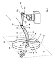
- the FIG. 1 is a front view of the device 1 according to the invention for producing a component which is at least partially formed from fiber composites, from a semifinished product 2, which may be the resulting component in an intermediate stage or a prefabricated part for this purpose.
- the component to be produced can in particular be an aircraft component.
- the semifinished product can be a prefabricated intermediate product or the component that is being formed be.
- the material can be placed on a tool molding or short a molding or a tool shape, such as a positive shape (Mandril), or on an already coated with material tool shape.
- a production of ribs in particular of CFK fuselage frames, an aircraft.
- prepreg fiber composites which are formed from a resin mixture, while maintaining a defined fiber volume content
- a soaked reinforcing fibers are used.
- the strength of the fiber composite material is determined essentially by the reinforcing fibers. In this way, the fiber volume fraction for a weight-optimized component can be selected to be relatively high.
- a preimpregnated fiber bundle or a fiber strand (roving), in particular a CFRP roving, can be used for coating the tool mold or the component.
- the apparatus 1 comprises one or more generally a dispenser 4 or applicator head 4 suitable for receiving and dispensing a predetermined maximum amount of material for the manufacture of the component.
- the dispenser 4 may comprise or consist of a spool for receiving and dispensing the material.
- the dispensing device may in particular comprise a housing in which the material is received, for example by means of the coil, and an opening provided therein for the passage of the material from the interior of the housing to the outside.
- the dispensing device may have a delivery device with which the delivery of the material can be influenced or controlled.
- the feeding device may include a motor with which the material can be dispensed or unwound from a spool.
- the motor When using a coil, the motor may drive the coil to receive material on the coil and / or to dispense from the coil.
- the engine may be in communication with a control device of the manufacturing device.
- the delivery device may include spring means for releasing the material against a biasing force.
- the dispensing device 4 may comprise at least one application device 44, for example a job roll for pressing or winding the composite strip 6 on or on the working surface 8 of the tool mold 10.
- the composite strip 6 is arranged on a within a housing 46 of the dispensing device 4 Roll, not shown, and is provided via this the applicator 44.
- the material for the use of the manufacturing apparatus according to the invention or the manufacturing method according to the invention is basically any layer material and in particular any band-shaped material into consideration.
- the material is a composite tape 6 (slit tape), i. a band made of a composite material.
- a unidirectional CFRP prepreg tape (UD-CFRP prepreg tape) suitable for producing high-strength structures can be used as composite strip 6.
- the material is placed in a defined manner on a working surface 8 of a tool mold 10 or a semifinished product 2.
- the material may be e.g. be placed on this or on this with a predetermined band path or a predetermined angle to the longitudinal direction of the mold or the semi-finished product.
- the material 6 can be placed on a mold, which is formed as a positive mold 10 (Mandril; winding mandrel).
- the tool mold 10 may have a substantially rectangular cross-section with four side surfaces 12, 14, 16, 18 forming a common working surface 8 which may be completely or partially coated with the material 6.
- several layers of the material 6 can be placed on the tool mold 10.
- the manufacturing device 1 has a guide track 22 for guiding a carriage 20. Since on the carriage 20, the dispensing device or the applicator head 4 is arranged, can with the Movement of the carriage 20 on the track 22, the dispensing device relative to the respective working surface 8 are moved.
- the dispenser 4 is rotatably mounted on the carriage 20.
- the axis of rotation of the dispensing device 4 can be fixed, that is rigid, or variable. In the latter case, the axis of rotation can thus be pivoted.
- the change in the axis of rotation can be done manually or with a controlled by a control device actuating device.
- the angle at which the material or the material strip is placed on the tool mold influenced and fixed, pivotable along a to the movement path, preferably in the direction of the working surface, employed pivot axis.
- the applicator head can be moved in a defined working position along the movement path or optionally rotated during a revolution along the movement path about the pivot axis, for example to form a spiral coating.
- the movement path is designed as a circular curved path, so that the section of the tool mold or component to be machined is located in the region of a center, preferably a center, of the movement path.
- the composite material For application of the composite material at an angle of 0 ° with respect to the longitudinal axis of the tool shape or the component of the carriage, for example, along the movement path in a region of the working surface of the mold or the component to be coated movable and the applicator head about the pivot axis in a working position, in which the composite material has an angle of 0 ° with respect to the longitudinal axis of the tool mold or the component.
- the applicator head is pivotable about the pivot axis into a working position in which the composite material at an angle in the range of more than 0 ° to about 90 °, preferably ⁇ 45 °, ⁇ 60 ° and / or 90 ° with respect to a longitudinal axis of the mold or the component can be applied to this.
- At least one application head for parallel application of at least one composite material, in particular a composite material band, can be provided for each work surface.
- applicator heads can be used by means of which multiple composite strip or strands are simultaneously applied to the mold or component.
- the angles of the individual composite strip bands or strands can be adjusted independently of one another, so that a spread in the direction of the larger radius of curvature is avoided in the case of curved tool shapes or components.
- the width of the composite tapes may be different when using applicator heads with multiple composite tapes, multiple applicator heads and / or carrier rings to further improve process efficiency.
- the guideway 22 may be formed as a closed path or as an open path or as a guideway section.
- the guideway 22 may in particular, as in the in the FIG. 1 illustrated embodiment, be designed as a circular path. To support the guideway 22, this may be arranged on a support member 24 or formed integrally therewith.
- the support member may be partially annular or formed as a closed ring and thereby each formed a total of annular.
- the guideway is curved to form a variable or constant curvature radius KR over the longitudinal extent thereof.
- the guideway is designed such that the carriage 20 can be moved on the inside of the guideway.
- the guideway may be formed curvilinear.
- the radius of curvature of the curved path at least partially corresponds to the curvature of the tool shape or the component.
- Tool molds or components which have a curvature profile with a plurality of radii of curvature can also be produced according to the invention.
- the guideway 22 and / or the carrier part are preferably located relative to the workpiece mold in such a way that the longitudinal extent of the guideway extends transversely to the longitudinal extent of an elongated workpiece shape, so that the guideway at least distances the tool mold 10 partially surrounds or surrounds.
- the support member 24 may be supported by a frame 30.
- a plurality of carrier rings along the longitudinal axis of the mold or the component can be arranged one behind the other, characterized in that in particular different angles of Verbundtechnikstoffb selected- or strands can be applied in one operation.
- the tool mold 10 may be positioned so as to be stationary or controlled relative to the support ring 24 in a relative movement between the guide track and the tool mold or the semi-finished, that the side surfaces 12, 16 of the mold or semi-finished parallel to the vertical axis 26 of the support ring 24 extend , Furthermore, the relative movement between the guide track and the tool mold or the semi-finished product can be mechanically adjusted or controlled such that the area of the surface on which the material 6 is placed at a given time in the region of a center M of the carrier ring 24, ie with a deviation of 10% of the radius of curvature KR, is arranged.
- the support ring has at least one running rail for receiving a roller assembly 32 of the carriage.
- the carriage 20 can be driven by the rollers.
- the support ring may have at least one toothed section, which can be brought into engagement with at least one drive wheel of the carriage.
- the drive wheel is, for example, as engaging in a rack of the support member gear educated.
- other drive systems can be used to move the carriage along the path of travel.
- the guideway includes a track rail, not shown, for receiving a roller assembly 32 of the carriage 20 and a schematically indicated gear portion 34 which engages with a drive wheel of the carriage 20, not shown.
- the toothing section 34 extends along the entire movement path 22.
- the drive wheel can be designed, for example, as a toothed wheel, which engages in a toothed rack of the carrier ring 24.
- the roller assembly 32 has two roller pairs 36, 38 spaced apart along the path of movement 22.
- the dispensing device 4 With a rotatability of the dispensing device 4 for adjusting the course of the longitudinal direction of the laid-up material 6, this is for the application of the material 6 rotatable about an employee employed to the movement path 22 in the direction of the mold 10 pivot axis 40.
- the tool shape or the component can be arranged such that the pivot axis 40 extends in the illustrated embodiment of the device at an angle of about 90 ° to an applied to the radius of curvature R of the trajectory 22 tangent 42 and through the center M of the circular path extends.
- the inventive device 1 is due to the along the working surface 8 encompassing trajectory 22 movable carriage 20, the pivotable dispensing device 4 and the feed movement between the mold 10 and trajectory 22 in the position, the curved mold 10 for the production of CFRP fuselage frames Device technology easy to coat.
- the application of the composite strip 6 on the work surface 8 can be flat, partial or according to other programmable patterns.
- the layer sequence and number of applied composite bands can be adjusted depending on the application.
- the composite material band 6 can be applied with different band angles with respect to the longitudinal axis of the tool mold 10.
- any intermediate angle and angle curves are adjustable. This will be explained in more detail below with reference to exemplary working positions A, B, C of the delivery device 4.
- the device according to the invention is thus able, in particular, to simply coat a curved tool shape or a curved component as well as other complex component geometries, characterized in that the term component in the context of the invention also means, in particular, a part of a component or a semifinished product. Due to the flexible angular orientation and the ability to apply local reinforcements, a weight reduction of the components is achieved with high strength.
- the sequence of layers and the number of layers applied can be varied depending on the application.
- the fiber flow can be adapted to the load path of the component, so that the production of lightweight, high-strength structures is possible.
- the composite may be applied to the work surface at an angle of about 0 °, ⁇ 45 °, ⁇ 60 °, and / or 90 ° with respect to the longitudinal axis of the tool mold or the longitudinal axis of the component.
- any intermediate angle and angle curves are adjustable by means of the device according to the invention.
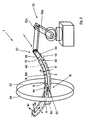
- FIG. 2 the a spatial representation of the device 1 from FIG. 1 shows, the composite strip 6 in the illustrated operating position A of the dispensing device 4 with a band angle ⁇ of 90 ° with respect to a longitudinal axis 48 of the mold 10 on the working surface 8 can be applied.
- the dispensing device 4 is pivoted about the pivot axis 40 in the working position A, in which the composite strip 6 is applied with the desired band angle ⁇ of 90 ° with respect to the longitudinal axis 48 on the tool mold 10 or on already applied strip material.
- An end portion 50 of the composite tape 6 is placed on the work surface 8 of the tool mold 10 and the dispenser 4 spaced from the work surface 8 by means of the in FIG. 2 not shown carriage 20 (see FIG.
- the band 6 is separated and the tool mold 10 relative to the movement path 22 corresponding to the amount of Bandwidth b procedure. This process is repeated until the desired region of the mold 10 is provided with a defined layer structure. Subsequently, interposed or preceded by this process, the composite strip 6 can be applied with other strip angles. For more efficient coating, the 90 ° band angle is reduced by an angular deviation that depends on the circumference of the tool mold 10 and the bandwidth b. This allows a continuous, spiral-shaped coating of the mold 10 in one operation. Depending on the rotational speed of the carriage 20 (see FIG. 1 ) along the movement path 22 and the feed speed of the tool mold 10, the band angle ⁇ can be set differently.
- the feed device is provided for carrying out a feed movement of the tool mold 10 or of the semifinished product 2 relative to the guide track 22 and has a coupling device for holding or fastening a section or an end section 54 of the tool mold 10 or the semifinished product 2.
- the feed device may comprise an actuator arm or robot arm 52 with the coupling device or a carriage 60 movable on a feed track 62 with the coupling device.
- the actuating arm or the robot arm 52 or the carriage 62 is moved by an adjusting mechanism or a guide device which is part of the feed device or is assigned to the feed device and is functionally connected thereto.
- the adjusting mechanism may in particular have the drive device for actuating the feed device.
- the guide device may have the functions for controlling, regulating the operation of the feed device or the adjusting mechanism.
- the adjusting mechanism or the guide device may in particular be part of a movement control.
- the motion control may control functions for the three-dimensional movement of the actuator arm or the robot arm 52 and the movement of the carriage 20 along the movement path 22 and / or the dispensing device 4 along the pivot axis 40 and / or the mold 10 or the semifinished product 2 and / or the Trajectory 22 each relative to each other.
- the coupling device of the delivery device with a combination of a feed track 62 with a movable on this carriage 60 or an actuator arm or robot arm 52 have a coupling device with which on the carriage 60 and the actuator arm or robot arm 52 and in particular An end portion 54 of the tool mold 10 or the semifinished product 2 can be fastened to one end section of the carriage 60 or arm 52.
- the tool mold 10 or the semifinished product 2 can be moved relative to the movement path 22 and / or the delivery device 4.
- the coupling device of the carriage 60 or of the positioning arm or robot arm 52 can be designed for fastening the tool mold 10 or the semifinished product 2 so that it can surround the tool mold 10 or the semi-finished product 2 and in particular an end section thereof at least in sections.
- other fastening means may be provided.
- the coupling device may be designed in such a way that it receives in particular a form-fitting manner an end section of the tool mold 10 or the semifinished product 2.
- the feed device can in particular have an actuating arm or robot arm 52 ( Figures 2 and 3 ), which is arranged outside the guide track 22 or the carrier ring 24 and which is connected to the tool mold, for example, such that it engages around an end portion 54 of the tool mold 10 in sections with a gripper 56.
- the adjusting arm 52 may in particular be formed from a first arm 52a and a second arm 52b, which is coupled to the first arm 52a by means of a joint 52c and on which the coupling device 57 is arranged.
- the tool shape or the semifinished product 10 is curved in the region of the frame in accordance with the cross section of the fuselage, so that it has an arcuate longitudinal axis 48.
- the semifinished product When using a semi-finished product without one Mold or when attaching the semifinished product to the coupling device, the semifinished product has been brought to this example by sewing or pre-curing in a dimensionally stable state.
- this or this can be moved relative to the movement path 22 along a curved path (feed path) by means of the arm 52 or the carriage 60.
- This curved path can be provided in such a way that it can be described in three dimensions. In particular, this can be located in a plane.
- the center line of the semifinished product or the mold is located in a plane, it can be provided that the curved path is also located in a plane.
- the connecting line of the centroids of the respective smallest cross sections along the longitudinal direction of the semifinished product or the tool mold can be used as center line.
- the curvature with the generally location-dependent radius of curvature RK which comprises the completed by the arm 52 or the end portion or the carriage 60 by the motion control or movement cam track
- the curvature or the radius of curvature R of the mold 10 in Reference to the longitudinal axis 48 or center line corresponds or retraces.
- a deviation of 10% with respect to the length of the semifinished product or the mold can be allowed.
- the tool mold 10 may further be positioned to the support ring 24 such that a tangent 58 at an angle of 90 degrees ⁇ 15 degrees, and more preferably ⁇ 5 degrees, to one of the machined portion 28 of the tool mold 10 is applied to the arc of curvature thereof relevant section of the guideway 22 spanned plane E runs.
- the device 1 is a control device, not shown, in particular with a CNC control assigned to the movement control of the carriage 20 along the movement path 22 and / or the delivery of the material from the dispensing device 4 and / or the rotation of the dispensing device 4 and / or If appropriate, the change of the pivot axis and / or the feed movement of the tool mold 10 or the semifinished product 2 relative to the movement path 22 is particularly advantageous if the movement of the carriage 20 along the movement path 22 and the Delivery movement of the mold 10 and the semifinished product 2 in dependence on each other.
- the feed movement of the tool mold 10 or of the semifinished product 2 can be effected, for example, synchronously with the movement of the carriage 20 and / or with a defined over or under reduction ratio to the band angle ⁇ (the angle between the longitudinal direction of the material when placing it on the surface 8 and the tangent to the central longitudinal axis of the tool mold 10 or the semi-finished product at the point where the material is currently placed on the surface 8, and seen in the tangential plane of the surface 8).
- the carrier ring 24 is moved relative to the tool mold 10.
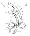
- FIG. 3 shows a spatial representation of the device 1 from FIG. 1 in which the dispensing device 4 is in a working position B according to which the composite strip 6 is applied to the working surface 8 at a band angle ⁇ of approximately 0 ° with respect to the longitudinal axis 48 of the tool mold 10.
- the dispensing device 4 is moved along the movement path 22 formed on the carrier ring 24 into a region of the working surface 8 of the tool mold 10 to be coated and around the pivot axis 40 in FIG pivoted the 0 ° working position B, in which the composite strip 6 with a band angle ⁇ of 0 ° with respect to the longitudinal axis 48 of the mold 10 can be applied to this.
- the end portion 50 of the composite tape 6 is placed on the work surface 8 by the applicator 44.
- the tool mold 10 is moved by means of the robot arm 52 along the curvature radius R of the tool mold 10 corresponding cam track relative to the movement path 22, characterized in that the composite strip 6 is placed on the working surface 8 by means of the dispensing device 4 (fiber laying).
- the dispenser 4 maintains its position on the carrier ring 24 while the tool mold 10 is moved relative to the carrier ring 24.
- the delivery device 4 is moved from the illustrated 9 o'clock position along the movement path 22 into a 6 o'clock or 12 o'clock position and subsequently into a 3 o'clock position.
- at least one dispensing device 4 can be provided for each side face, characterized in that the coating of the side faces can take place at the same time.
- the bandwidth b of at least one dispensing device 4 can also be selected such that the side surfaces 12, 14, 16, 18 are completely covered with the composite strip 6 in one operation at a time.
- the carrier ring 24 is moved relative to the tool mold 10.
- a composite material designed as a composite strip can be applied according to the solution according to the invention with different strip angles with respect to a longitudinal axis of the tool shape or of the component.
- FIG. 4 a spatial representation of a device 1 with a working position C of the dispensing device 4 is shown, in which the composite strip 6 with a Band angle ⁇ of 45 ° with respect to the longitudinal axis 48 of the tool mold 10 is applied to the working surface 8.
- the dispensing device 4 is rotated about the pivot axis 40 in a 45 ° position.
- the tool mold 10 is moved according to the radius of curvature R of the tool mold 10 relative to the movement path 22 and the dispensing device 4 along the movement path 22, characterized in that the composite strip 6 is wound around the tool mold 10 by means of the dispenser 4.
- the tool mold 10 is guided by a feed carriage 60 which is movable along a feed track 62, the mold or the semi-finished or the same end of the same by means of the coupling device can be attached to the delivery carriage 60.
- the coupling device can have a gripper 64, with which a section or an end section 54 of the tool mold 10 can be encompassed at least in sections.
- the feed path 62 is formed in this variant as a curved path on a support member 66.
- the radius of curvature RZ of the feed track 62 may in particular correspond to the radius of curvature R of the tool mold 10.
- the tool mold 10 is positioned such that the portion 28 of the tool mold 10 to be machined is located in the region of the center of the carrier ring 24.
- the support member 66 has a running rail, not shown, for receiving a roller assembly 68 of the Zustellwagens 60 and has a schematically indicated toothing portion 70 which is in engagement with a not illustrated drive wheel of the Zustellwagens 60.
- the toothing section The roller arrangement 68 has two roller pairs 72, 74 spaced apart from one another along the feed track 62.
- the drive wheel may be designed, for example, as a toothed wheel which engages in a toothed rack of the carrier part 66.
- the carrier ring it is possible to arrange more than one application head along the movement path of the carrier ring.
- at least one pair of applicator heads displaceable by an angle of approximately 180 ° relative to one another on the movement path can be provided.
- An advantage of a 180 ° offset from each other arrangement of the application heads is the compensation of the pressure forces on the mold or the component.
- a complete coverage of the tool mold or the component can be achieved with a single operation with reduced weight of the device.
- the application heads can also be moved independently of each other, characterized in that it is advantageous if the control of the application heads is based on a common time base.
- the device for producing ribs, in particular CFRP fuselage ribs, or fuselage segments of an aircraft has proved to be particularly advantageous.
- the web and flange height and the thickness of the layer structure may be variable or constant along the longitudinal extent of the component.
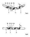
- FIGS. 5 and 6 showing an individual representation of the partially coated tool mold 10 FIG. 4 show in a side view and a plan view
- a plurality of application heads 4 can be used to improve the process efficiency, by means of which at the same time a plurality of composite bands 6 are applied to the work surface 8.
- four composite bands 6a, 6b, 6c, 6d were applied simultaneously.
- the band angles of the individual composite bands 6a, 6b, 6c, 6d can be adjusted independently of each other, so that the occurring in curved molds 10, in FIG. 5 shown band spread in the direction of the larger radius of curvature RG of the tool mold 10 is avoided.
- the widths b of the composite tapes 6a, 6b, 6c, 6d may be different when using applicator heads 4 with multiple composite tapes to further improve process efficiency.
- the bulkhead may have a C-shaped cross-section and be formed in one piece.
- the frame can have several sub-profiles, such as an L and a C-profile.
- a frame with E-shaped cross section can be produced.
- two cores are preferably used, which are coated separately and then together in a first step.
- two cores are preferably used, which are likewise coated separately and then together in a first working step.
- a leg of the profile is bent by means of a thermoforming process at an angle of for example 90 ° to the profile web.
- the angle between the web and the flange may be greater or less than 90 ° for all cross-sectional variants in order to ensure a flush connection of the flange to a curved surface of the aircraft fuselage.
- Stepped recesses of the flanges for the attachment limbs of the aircraft longitudinal stiffeners can already be provided during the production of the frames or, for example after the penetration of the penetrations for the aircraft longitudinal stiffeners, are formed by means of a thermoforming method.
- the tool mold has at least one pair of groove-shaped recesses arranged diametrically opposite one another, each extending parallel to a longitudinal axis of the tool mold.
- the groove-shaped recesses serve as an outlet for the separating blade of a separating device which is used to separate the fiber composite structure into two or four profiles.
- the created fiber composite structure may be separated into two approximately C-shaped or four L-shaped profiles which may be used as frames or parts of a frame. The separation of the composite structure can be done before or after curing.
- the component is preferably after the separation process in a negative mold, optionally additionally with a core, for example, a part of the then multi-part mold, inserted and cured.
- a separation after curing the unseparated component, possibly inserted in a negative mold, is evacuated together with the mold and cured in an autoclave. Subsequently, the cured component is separated and removed from the mold.
- a composite material with a defined angle is applied to at least one working surface of a tool mold or a component by means of at least one application head, characterized in that the application head via at least one carriage along a work surface at least partially encompassing movement path is moved relative to the work surface.
- the application head is pivoted, in particular rotated, along a pivot axis which is set towards the movement path.
- the tool mold or the component and the movement path are preferably moved relative to each other for applying the composite material to the work surface.
- the composite strip is preferably applied to the work surface in accordance with the component contour to be produced.
- the tool mold 10 has two diametrically arranged approximately U-shaped recesses 76, 78, which are introduced into the side surfaces 14, 18 of the mold 10 and each parallel to the longitudinal axis 48 (see FIG. 2 ) of the tool mold 10.
- the groove-shaped recesses 76, 78 serve as an outlet for the separating blade of a separating device, not shown, which is used to separate the fiber composite material structure 2.
- the created fiber composite structure 2 can be separated in the mold 10 with approximately rectangular cross section, for example, in two C-shaped profiles 80, which are used for CFRP frames of an aircraft.
- the C-frames 80 each have two flanges 82, 84, which are connected by a web 86, characterized in that the angle between the upper and lower flange and the web is in each case about 90 °.
- the web and flange height and the thickness of the layer structure can be variable or constant along the longitudinal extension of the frames 80.
- the separation of the composite component 2 can take place before or after curing. If the separation takes place before curing, the component 2 is preferably inserted into a negative mold, optionally additionally with a core, after the separation process and cured. In a separation after curing, the unseparated component, possibly inserted in an additional negative mold, evacuated together with the mold and cured in an autoclave. Subsequently, the cured component is separated and removed from the mold.
- FIG. 8 shows an individual view of a CFK hull rib 88 with an approximately C-shaped cross-section according to another embodiment.
- the bulkhead 88 has two flanges 90, 92 which are connected by a web 94, characterized in that the angle between the upper flange 90 and the web 94 about 90 ° and the angle between the lower flange 92 and the web 94 approximately 110 °, to ensure a flat connection of the flange 92, for example, to the curved surface 96 of an aircraft fuselage.
- the rib 98 can have a plurality of partial profiles, such as, for example, an L and a C Profile 106, 108 have.
- the C-profiles 106 are, for example, according to the description of FIG. 7 produced.
- a preferred tooling for producing the L-shaped profiles 108 will be described below FIG. 10 explained in more detail.
- the mold 10 has according to FIG. 10 two pairs of diametrically arranged, approximately U-shaped recesses 110, which are parallel to the longitudinal axis 48 (see FIG. 2 ) of the tool mold 10 in the region of the side surfaces 12, 14, 16, 18 extend.
- the groove-shaped recesses 110 are used, as already explained, as an outlet for the separating blade of a separating device, not shown, which is used to separate the fiber composite component 2.
- the four curved L-profiles 106 can be removed from the tool mold 10.
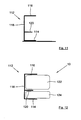
- FIG. 11 shows an embodiment of a CFK hull rib 112 with an approximately E-shaped cross-section.
- the integrally formed bulkhead 112 has two flanges 114, 116, which are connected by means of a web 118, characterized in that between the flanges 114, 116, a stiffening rib 120 is arranged.
- the stiffening rib 120 extends parallel to the flanges 114, 116, characterized in that the angle between the lower and upper flange 114, 116 and the web 118 and the angle between the stiffening rib 120 and the web in the illustrated embodiment about 90 ° is.
- the CFK hull frame 112 out FIG. 11 with tool mold 10 shows, characterized in that only one component half is shown, find its manufacture two cores 122, 124 use, which are coated individually and then together in a first step.
- the upper core 122 has a opposite the lower core 124 enlarged cross-sectional area, so that the distance between the flange 116 and the reinforcing rib 120 is increased relative to the distance of the flange 114 to the reinforcing rib 120.
- one-piece frames 126 with LCF cross section are according to FIG. 14 showing the CFK-hull bulkhead 126 with tool mold 10, characterized in that only one half of the component is shown, also two cores 128, 130 are used, which are coated separately and then together in a first step.
- the leg portion 100 of the profile 126 is bent by means of a thermoforming method - as indicated by an arrow - at an angle of for example 90 ° to the flange 100.
- Stepped recesses (not shown) of the flanges 92, 100, 114, for fastening limbs of aircraft longitudinal stiffeners, so-called stingers, can already be provided during the production of the frames 80, 88, 98, 112, 126 or, for example after the introduction of the not shown Breakthroughs for the stringers are formed by a thermoforming process.
- the device according to the invention is not limited to the described embodiment with only one dispensing device 4, but a plurality of applicator heads 4 can be movably arranged along the movement path 22 of the carrier ring 24 in order to further optimize the process speed.
- the application heads 4 can be moved independently of each other, characterized in that it is advantageous if their control is based on a common time base. For example, two offset by an angle of about 180 ° to each other on the movement path 22 movable applicator heads 4 are provided.
- the compensation of the pressure forces on the tool mold 10 or the component 2 is advantageous in the case of an arrangement of the application heads 4 that is staggered by 180.degree ..
- the invention is not limited to the embodiment shown with only one carrier ring 24, for example several carrier rings 24 can be serially connected be arranged one behind the other, wherein it can be provided that in particular composite bands 6 with different band angles in one Operation can be applied.
- the invention is also not limited to curved tool molds 10 or components 2.
- a tool mold having a substantially rectangular cross section preferably all four side surfaces of the tool mold are occupied, characterized in that the application head is moved in each case by 90 ° along the movement path.
- the applicator head is pivoted along the trajectory to a 3, 6, 9, and 12 o'clock position.
- at least one application head can be provided for each work surface, characterized in that the coating of the side surfaces takes place at the same time.
- a layer structure with an angle of more than 0 ° to about 90 °, preferably ⁇ 45 °, ⁇ 60 ° and / or 90 ° with respect to the longitudinal axis of the mold or the component of the applicator head is pivoted about the pivot axis in a working position, in which is applied to the composite with the desired angle to the working surface, characterized in that the tool shape or the component is moved relative to the movement path and the carriage along the movement path (fiber winding).
- the angle can be set differently.
- the applicator head is rotated to a 90 ° position, an end portion of the composite tape is pressed onto the work surface and the applicator head is rotated 360 ° along the path of travel by the carriage, characterized in that a composite strip is applied to the composite web Tool mold is applied. Subsequently, the tape is separated and the tool shape or the component along the feed path according to the amount of a bandwidth proceed.
- the 90 ° angle is reduced or increased by a deviation that depends on the circumference of the mold or component and the bandwidth.
- the angle of the following layer of the composite material can be correspondingly increased or decreased by a deviation, so that the material properties are balanced. This allows a continuous, spiral-shaped coating of the mold or the component.
- a carrier ring having the movement path is moved relative to the tool shape or the component.
Landscapes
- Engineering & Computer Science (AREA)
- Mechanical Engineering (AREA)
- Chemical & Material Sciences (AREA)
- Composite Materials (AREA)
- Physics & Mathematics (AREA)
- Nonlinear Science (AREA)
- Robotics (AREA)
- Moulding By Coating Moulds (AREA)
- Reinforced Plastic Materials (AREA)
- Nonwoven Fabrics (AREA)
- Laminated Bodies (AREA)
Description
- Die Erfindung betrifft eine Vorrichtung zur Herstellung eines Faserverbundwerkstoff (FVW)-Bauteils, und ein Verfahren zur Herstellung eines Faserverbundwerkstoffbauteils.
- Die Dokumente
DE 38 43 488 A1 ,US 3 397 847 A undWO 91/04843 - Die
DE 41 22 785 A1 beschreibt eine Wickelanlage zur Herstellung von Bauelementen aus faserverstärkten Kunststoffen mit einem Wickelkopf zur Ablage von Längsverstärkungen mit kleinen Fasserwickeln bezogen auf die Wickelachse. Die Wickelanlage weist einen auf einer zusätzlichen Schlittenführung der Wickelanlage parallel zu einem Wickelkopf verfahrbaren Schlitten sowie eine auf einem Rotor angeordnete Fadenführung mit einer Abspuleinheit mit einem Spulenträger auf. - Die
WO 2005/018917 A2 beschreibt eine Vorrichtung zum Auftragen von Laminierfäden oder Laminierbändern auf eine drehbar gelagerte Trommel zur Herstellung eines Verbundbauteils. Das Auftragen der Laminierfäden erfolgt mittels Abgabevorrichtungen, die auf einem Ring verfahrbar und an einer Lagerachse drehbar gelagert sind. - Aus der
WO 2006/060270 A1 ist eine Abgabevorrichtung zur Abgabe und zum Auftragen von Laminierbändem auf eine Auftragsoberfläche bekannt. - Zur Steigerung der Produktivität, Flexibilität und Wirtschaftlichkeit moderner Verfahren zur Herstellung von Faserverbundwerkstoffbauteilen hat im Wesentlichen die Automatisierungstechnik beigetragen, dadurch gekennzeichnet, dass automatisch arbeitende Faserlegevorrichtungen, sogenannte Automated Fiber Placement-Systeme (AFP-Systeme), neben den manuellen Verfahren immer mehr an Bedeutung gewinnen.
- Insbesondere durch den Einsatz derartiger automatischer Faserlegevorrichtungen mit einem oder mehreren verfahrbaren Auftragsköpfen, mittels derer ein vorimprägniertes Faserverbundwerkstoffband, beispielsweise ein unidirektionales CFK-Prepreg-Band (UD-CFK-Prepreg-Band), auf eine Arbeitsoberfläche einer Werkzeugform oder eines Bauteils aufgebracht wird, ergeben sich im Bereich der Fertigung kürzere Durchlaufzeiten mit einer höheren Auslastung des Fertigungspotentials und daraus resultierend verringerte Herstellungskosten der Verbundwerkstoffprodukte. Die durch manuelle Arbeiten bedingten Nebenzeiten können bei hoher Fertigungsqualität auf ein Minimum reduziert werden.
- Eine derartige Vorrichtung zur Herstellung von Faserverbundwerkstoffbauteilen ist beispielsweise aus der
WO 2005/105641 A2 bekannt. Diese herkömmliche Faserlegevorrichtung verwendet eine Vielzahl von unabhängig voneinander verschwenkbaren Auftragsköpfen mittels derer Verbundwerkstoffbänder auf eine Arbeitsoberfläche einer Werkzeugform aufbringbar sind. Hierzu sind die Auftragsköpfe jeweils auf einem Trägersystem angeordnet, das auf Führungsschienen parallel zu einer Längsachse der zu beschichtenden Werkzeugform verfahrbar ist. Eine rotationssymmetrische Werkzeugform kann entlang ihrer Längsachse drehbar zwischen den Auftragsköpfen gelagert sein, so dass ihre Umfangsfläche bei einer Umdrehung der Werkzeugform und Axialverschiebung der Auftragsköpfe entlang der Führungsschienen mit dem Verbundwerkstoffband beschichtet wird. Nachteilig bei derartigen Faserlegevorrichtungen ist, dass diese vorrichtungstechnisch aufwendig und aufgrund der parallel zu der Längsachse der Werkzeugform angeordneten Führungsschienen nicht zur Beschichtung von Werkzeugformen mit einer gekrümmten Längsachse geeignet sind. - Demgegenüber liegt der Erfindung die Aufgabe zugrunde, eine Vorrichtung und ein Verfahren zur Herstellung von Faserverbundwerkstoffbauteilen, die insbesondere auch in ihrer Längsrichtung gekrümmt gestaltet sind, sowie ein nach einem derartigen Verfahren hergestelltes Faserverbundwerkstoff-Bauteil zu schaffen, bei denen gegenüber herkömmlichen Lösungen eine weitgehend automatisierbare Fertigung bei verringertem vorrichtungstechnischen Aufwand ermöglicht ist.
- Diese Aufgaben werden durch die Merkmale der unabhängigen Ansprüche gelöst. Weitere Ausführungsformen sind in den auf die unabhängigen Ansprüche rückbezogenen Unteransprüchen angegeben.
- Erfindungsgemäß ist insbesondere eine Vorrichtung zur Herstellung eines FVW-Bauteils mit zumindest einer Abgabe-Vorrichtung zum Auflegen mindestens eines Materials und insbesondere mindestens eines bandförmigen Materials auf eine Oberfläche einer Werkzeugform oder eines Halbzeugs zur Herstellung des FVW-Bauteils vorgesehen. Die Vorrichtung weist zumindest einen Laufwagen, auf dem die Abgabe-Vorrichtung angeordnet ist, und eine die Oberfläche zumindest teilweise in deren Umfangsrichtung umlaufende Führungsbahn auf, auf welcher der Laufwagen zum Verfahren der Abgabe-Vorrichtung relativ zu der Oberfläche bewegbar ist. Dabei kann die Abgabe-Vorrichtung um eine zu der Führungsbahn winklig verlaufende Schwenkachse schwenkbar oder drehbar sein. Die Vorrichtung kann insbesondere derart gestaltet sein, dass die Werkzeugform oder das Halbzeug und die Bewegungsbahn relativ zueinander bewegbar sind.
- Für einen speziellen vorteilhaften Anwendungsfall, bei dem das Halbzeug mehr oder weniger nur in Umfangsrichtung beschichtet wird, kann die Vorrichtung eine Führungseinrichtung zur Bewegung der Werkzeugform oder des Halbzeugs und der Bewegungsbahn relativ zueinander aufweisen.
- Gemäß einem Ausführungsbeispiel der Erfindung kann eine Zustellvorrichtung und/oder die Führungseinrichtung derart gestaltet sein, dass die Werkzeugform oder das Halbzeug nicht nur entlang seiner Längsrichtung bewegt werden kann, sondern auch senkrecht dazu. Somit kann die Werkzeugform oder das Halbzeug von der Führungseinrichtung auf dreidimensional zu beschreibende Art und Weise geführt bzw. bezüglich der Führungsbahn zugestellt werden.
- Ferner kann gemäß eines Ausführungsbeispiels die Zustellvorrichtung und/oder die Führungseinrichtung derart gestaltet sein, dass die Werkzeugform bzw. das Halbzeug derart geführt werden, dass es lediglich axial, d.h. entlang seiner Längsrichtung verschoben wird und/oder um eine senkrecht zur Längsrichtung stehende Achse herum gedreht wird, jedoch nicht um eine Achse gedreht wird, die in Längsrichtung verläuft. Das bedeutet unter anderem, dass bei diesem Ausführungsbeispiel während des Auftragens des Materials aus den Auftragsköpfen, insoweit die Auftragung entlang einer derartigen Richtung auf der Oberfläche der Werkzeugform bzw. das Halbzeug erfolgt, welche Richtung eine Komponente senkrecht zur Längsrichtung, d.h. in umfänglicher Richtung der Werkzeugform bzw. des Halbzeugs hat, die umfängliche Auftragung aus der Bewegung des Laufwagens auf der Führungsbahn resultiert.
- Die Zustellvorrichtung und/oder die Führungseinrichtung kann derart gestaltet sein, dass, bei einer vorbestimmten Krümmung der Werkzeugform oder des Halbzeugs in Längsrichtung mit einem entlang der Längsrichtung variablen oder nicht-variablen Krümmungsradius, die Richtung des Krümmungsradius auf den momentanen Mittelpunkt des Bereichs, auf den das bandförmige Material von der Abgabe-Vorrichtung aus auf die Oberfläche der Werkzeugform oder des Halbzeugs aufgelegt wird, um maximal 30 Grad von der Radialebene abweicht, die in dem relevanten Abschnitt von der Bewegungsbahn oder von der Vertikalen auf die Tangentialebene der Führungsbahn an der momentanen Stelle des Wagens aufgespannt wird. Die Führungseinrichtung zur Bewegung der Werkzeugform oder des Halbzeugs und der Bewegungsbahn relativ zueinander kann auch derart gestaltet sein, dass, bei einer vorbestimmten Krümmung der Werkzeugform oder des Halbzeugs in Längsrichtung mit einem entlang der Längsrichtung variablen oder nicht-variablen Krümmungsradius, die Richtung des Krümmungsradius auf den Mittelpunkt des Bereichs, auf den das bandförmige Material von der Abgabe-Vorrichtung aus auf die Oberfläche der Werkzeugform oder des Halbzeugs aufgelegt wird, um maximal 30 Grad von der Radialebene abweicht, die von der Bewegungsbahn aufgespannt wird.
- Die Zustellvorrichtung und/oder die Führungseinrichtung kann insbesondere derart gestaltet sein, dass, bei einer vorbestimmten Krümmung der Werkzeugform oder des Halbzeugs in Längsrichtung mit einem entlang der Längsrichtung variablem oder nichtvariablem Krümmungsradius, die Richtung des Krümmungsradius auf den momentanen Mittelpunkt des Bereichs, auf den das bandförmige Material vom Abgabe-Vorrichtung aus auf die Oberfläche der Werkzeugform oder des Halbzeugs aufgelegt wird, um maximal 30 Grad von der Radialebene abweicht, die in dem relevanten Abschnitt von der Bewegungsbahn aufgespannt wird, oder von der Vertikalen auf die Tangentialebene der Führungsbahn an der momentanen Stelle des Wagens. Die Führungseinrichtung zur Bewegung der Werkzeugform oder des Halbzeugs und der Bewegungsbahn relativ zueinander kann auch derart gestaltet sein, dass, bei einer vorbestimmten Krümmung der Werkzeugform oder des Halbzeugs in Längsrichtung mit einem entlang der Längsrichtung variablen oder nicht-variablen Krümmungsradius, die Richtung des Krümmungsradius auf den Mittelpunkt des Bereichs, auf den das bandförmige Material vom Abgabe-Vorrichtung aus auf die Oberfläche der Werkzeugform oder des Halbzeugs aufgelegt wird, um maximal 30 Grad von der Radialebene abweicht, die von der Bewegungsbahn aufgespannt wird.
- Die Führungsbahn kann eine zumindest abschnittsweise kreisförmige Kurvenbahn bilden. Die Führungsbahn kann weiterhin an einem zumindest abschnittsweise ringförmigen Trägerteil ausgebildet sein, der die Werkzeugform oder das Halbzeug zumindest teilweise umgibt oder umläuft. Dabei kann die Führungsbahn abschnittsweise quer zur Längsrichtung der Werkzeugform oder des Halbzeugs verlaufen.
- Die Führungsbahn kann zumindest eine Laufschiene zur Aufnahme einer Rollenanordnung des Laufwagens aufweisen, wobei eine rolle oder mehrere Rollen motorisch angetrieben sein können. Zusätzlich oder alternativ kann die Führungsbahn zumindest einen Verzahnungsabschnitt aufweisen, der mit mindestens einem Antriebsrad des Laufwagens in Eingriff bringbar ist.
- Die Herstellungsvorrichtung kann eine Steuerungsvorrichtung zur Ansteuerung der Führungseinrichtung aufweisen, durch die eine Relativbewegung zwischen der Werkzeugform oder des Halbzeugs und der Führungsbahn aufgrund manueller Vorgaben oder automatisch erfolgen kann. Die Steuerungsvorrichtung und die Führungseinrichtung können derart ausgebildet sein, dass die Führungsbahn gegenüber der Werkzeugform oder dem Halbzeug bewegt werden kann. Dabei können die Steuerungsvorrichtung und die Führungseinrichtung derart ausgebildet sein, dass die Werkzeugform oder das Halbzeug gegenüber der Führungsbahn oder umgekehrt bewegt werden kann. Dabei kann mit der Steuerungsvorrichtung und der Führungseinrichtung die Werkzeugform oder das Halbzeug gegenüber der Führungsbahn derart bewegt werden, dass der Winkel zwischen der Längserstreckung des bandförmigen Materials zwischen der Abgabe-Vorrichtung und der Stelle der Oberfläche der Werkzeugform oder des Halbzeugs auf den während des Auflegens des bandförmigen Materials dasselbe aufgelegt wird, und der Radialebene in der Radialebene gesehen, kleiner als 30 Grad beträgt.
- Die Steuerungsvorrichtung und die Führungseinrichtung können derart ausgebildet sein, dass mit der Steuerungsvorrichtung und der Führungseinrichtung die Bewegung des Laufwagens entlang der Führungsbahn zum Auflegen des Materials auf die Oberfläche der Werkzeugform oder auf die Oberfläche des Halbzeugs und/oder die Drehbewegung der Abgabe-Vorrichtung gesteuert werden kann. Auch kann die Steuerungsvorrichtung und die Führungseinrichtung derart ausgebildet sein, dass mit der Steuerungsvorrichtung und der Führungseinrichtung die Abgabe des Materials vom Auftragkopf auf die Oberfläche der Werkzeugform oder die Oberfläche des Halbzeugs gesteuert werden kann. Mit der Steuerungsvorrichtung und der Führungseinrichtung kann der Krümmungsradius der Kurvenbahn zumindest abschnittsweise dem Krümmungsradius der Werkzeugform oder des Halbzeugs entsprechen.
- Dabei kann insbesondere eine im Bereich eines zu bearbeitenden Abschnitts der Werkzeugform oder des Halbzeugs an den Krümmungsradius der Werkzeugform oder des Halbzeugs angelegte Tangente einen Winkel von etwa 90° (d.h. ±15 Grad) zu einer von der Bewegungsbahn aufgespannten Radialebene aufweisen.
- Die Führungseinrichtung zur Bewegung der Werkzeugform oder des Halbzeugs kann zumindest einen Roboterarm aufweisen. Dabei kann der Roboterarm außerhalb der Bewegungsbahn des Laufwagens angeordnet sein und zur Kopplung mit der Werkzeugform oder dem Halbzeug einen Endabschnitt der Werkzeugform oder des Halbzeugs halten oder zumindest abschnittsweise umgreifen.
- Die Vorrichtung oder die Führungseinrichtung zur Bewegung der Werkzeugform oder des Halbzeugs kann eine Zustellbahn oder einen Träger oder ein Trägerteil und einen auf dieser bewegbaren Zustellwagen aufweisen, an dem die Werkzeugform oder das Halbzeug gehalten werden kann. Das Trägerteil kann zumindest eine Laufschiene zur Aufnahme einer Rollenanordnung des Zustellwagens aufweisen. Auch kann das Trägerteil zumindest einen Verzahnungsabschnitt aufweisen, der mit mindestens einem Antriebsrad des Zustellwagens in Eingriff bringbar ist.
- Die Steuerungseinrichtung kann eine CNC-Steuerung aufweisen, die eine Funktion aufweist, mit der die Bewegungssteuerung des Laufwagens entlang der Bewegungsbahn, der Abgabe-Vorrichtung entlang der Schwenkachse und/oder der Werkzeugform bzw. des Halbzeugs und der Bewegungsbahn relativ zueinander erfolgt.
- Die Bewegung des Laufwagens entlang der Führungsbahn und die Zustellbewegung der Werkzeugform bzw. des Halbzeugs und/oder der Führungsbahn können durch eine Kopplungseinrichtung miteinander gekoppelt sein.
- Die Steuerungsvorrichtung kann eine Funktion zur Ansteuerung der Führungseinrichtung aufweisen, mit der das bandartige Material flächig, partiell auf die Oberfläche aufgebracht werden kann.
- Auch kann die Steuerungsvorrichtung eine Funktion zur Ansteuerung der Führungseinrichtung aufweisen, mit der ein Muster gespeichert werden kann, mit dem das bandartige Material flächig oder partiell auf die Oberfläche aufgebracht werden kann.
- Generell können mehrere Auftragsköpfe an einem Laufwagen oder mehrere Laufwagen, die auf der Führungsbahn bewegbar sind, die jeweils zumindest eine Abgabe-Vorrichtung aufweisen, vorgesehen sein.
- Die Vorrichtung kann mehrere Führungsbahnen mit jeweils einem Laufwagen oder mehreren Laufwagen aufweisen.
- Die Steuerungsvorrichtung und die Führungseinrichtung können derart gestaltet sein, dass mit diesen mehrere Auftragsköpfe zum parallelen Auflegen des bandartigen Materials angesteuert werden können.
- Die Steuerungsvorrichtung kann so vorgesehen sein, dass zwei Auftragsköpfe in Umfangsrichtung der Werkzeugform oder des Halbzeugs gesehen um einen Winkel von 180 Grad ± 30 Grad zueinander versetzt bewegt werden können.
- Die Führungsbahn und die Drehstellung der Abgabe-Vorrichtung kann hinsichtlich der mit dem Material zu belegenden Oberfläche der Werkzeugform oder des Halbzeugs derart einstellbar sein, dass der Verbundwerkstoff mit einem Winkel α von 0 Grad ± 15 Grad bezüglich der Längsachse der Werkzeugform oder des Halbzeugs auf die Werkzeugform oder das Halbzeug aufbringbar ist.
- Die Steuerungsvorrichtung kann so vorgesehen sein, dass die Führungsbahn und die Drehstellung der Abgabe-Vorrichtung hinsichtlich der mit dem Material zu belegenden Oberfläche der Werkzeugform oder des Halbzeugs derart einstellbar sind, dass der Verbundwerkstoff mit einem Winkel α im Bereich von mehr als 0° bis etwa 90°, vorzugsweise von ±45 Grad, ±60 Grad und/oder 90 Grad, jeweils ± 5 Grad, bezüglich der Längsachse der Werkzeugform oder des Halbzeugs auf die Werkzeugform oder das Halbzeug aufbringbar ist.
- Erfindungsgemäß ist weiterhin ein Verfahren zur Herstellung eines FVW-Bauteils mit zumindest einer Abgabe-Vorrichtung zum Auflegen mindestens eines bandförmigen Materials auf eine Oberfläche einer Werkzeugform oder eines Halbzeugs zur Herstellung des FVW-Bauteils vorgesehen, wobei die Abgabe-Vorrichtung auf einem Laufwagen angeordnet entlang einer die Oberfläche zumindest teilweise in deren Umfangsrichtung umlaufenden Führungsbahn gefahren wird und dabei das bandförmige Material abgibt und auf die Oberfläche auflegt. Dabei kann vorgesehen sein, dass die Abgabe-Vorrichtung manuell oder mit einer Steuerungsvorrichtung mit entsprechenden Funktionen sowie ein Führungsvorrichtung gesteuert zur Einstellung des Verbundwerkstoffwinkels entlang einer zu der Bewegungsbahn angestellten Schwenkachse verschwenkt wird. Dabei kann vorgesehen sein, dass die Werkzeugform oder das Bauteil und die Bewegungsbahn relativ zueinander verfahren werden.
- Bei diesen Varianten kann weiterhin vorgesehen sein, dass die Führungsbahn und die Drehstellung der Abgabe-Vorrichtung hinsichtlich der mit dem Material zu belegenden Oberfläche der Werkzeugform oder des Halbzeugs derart eingestellt sind, dass der Verbundwerkstoff mit einem Winkel α von 0 Grad ± 15 Grad bezüglich der Längsachse der Werkzeugform oder des Halbzeugs auf die Werkzeugform oder das Halbzeug aufgelegt wird.
- Alternativ hierzu kann vorgesehen sein, dass die Führungsbahn und die Drehstellung der Abgabe-Vorrichtung hinsichtlich der mit dem Material zu belegenden Oberfläche der Werkzeugform oder des Halbzeugs derart eingestellt sind, der Verbundwerkstoff mit einem Winkel α im Bereich von mehr als 0° bis etwa 90°, vorzugsweise von ±45 Grad, ±60 Grad und/oder 90 Grad, jeweils ± 5 Grad, bezüglich der Längsachse der Werkzeugform oder des Halbzeugs auf die Werkzeugform oder das Halbzeug aufgelegt wird.
- Die Steuerungsvorrichtung kann so vorgesehen sein, dass die Führungsbahn in einem Bereich der mit dem Material zu belegenden Oberfläche der Werkzeugform oder des Halbzeugs und die Drehstellung der Abgabe-Vorrichtung derart eingestellt werden, dass das bandförmige Material mit einem Winkel α im Bereich von 45 Grad ± 5 Grad bezüglich der Längsachse der Werkzeugform oder des Halbzeugs in entgegensetzten Längsrichtungen der Werkzeugform oder des Halbzeugs aufgebracht wird, wobei das bandförmige Material eine Breite b in Abhängigkeit des Umfangs C der Werkzeugform bzw. des Bauteils gemäß der Formel

± 10% aufweist. - Mit dem vorgenannten Verfahren kann vorgesehen sein, dass als FVW-Bauteil ein Spant, insbesondere ein CFK-Rumpf-Spant oder ein Rumpfsegment eines Flugzeugs hergestellt wird.
- Bei dem Verfahren kann als Werkzeugform eine Werkzeugform verwendet werden, die zumindest ein Paar diametral zueinander angeordnete nutförmige Ausnehmungen aufweist, die sich jeweils parallel zu der Längsachse der Werkzeugform erstrecken.
- Als Material und insbesondere bandförmiges Material kann ein Material verwendet werden, das aus einem vorimprägnierten Faserverbundwerkstoffband, insbesondere einem unidirektionalen CFK-Prepreg-Band (UD-CFK-Prepreg-Band), gebildet ist. Alternativ hierzu kann ein Material verwendet werden, das aus einem vorimprägnierten Faserbündel oder einem vorimprägnierten Faserstrang (Roving), insbesondere einem CFK-Roving, gebildet ist.
- Im Folgenden werden bevorzugte Ausführungsbeispiele der Erfindung anhand schematischer Zeichnungen näher erläutert. Es zeigen:
- ■
Figur 1 eine Vorderansicht einer Vorrichtung zur Herstellung eines Faserverbundwerkstoffbauteils gemäß einem ersten erfindungsgemäßen Ausführungsbeispiel; - ■
Figur 2 eine räumliche Darstellung der Vorrichtung ausFigur 1 , gemäß der sich ein Abgabe-Vorrichtung in einer 90°-Arbeitsstellung befindet; - ■
Figur 3 eine räumliche Darstellung der Vorrichtung ausFigur 1 , dadurch gekennzeichnet, dass sich der Abgabe-Vorrichtung in einer 0°-Arbeitsstellung befindet; - ■
Figur 4 eine räumliche Darstellung einer Vorrichtung gemäß einem zweiten erfindungsgemäßen Ausführungsbeispiel, dadurch gekennzeichnet, dass sich die Abgabe-Vorrichtung in einer 45°-Arbeitsstellung befindet; - ■
Figur 5 eine Seitenansicht der teilweise mit etwa ±45° Faserorientierungen beschichteten Werkzeugform ausFigur 4 ; - ■
Figur 6 eine Draufsicht der teilweise beschichteten Werkzeugform ausFigur 4 ; - ■
Figur 7 ein bereits teilweise entformtes Faserverbundwerkstoffbauteil und die zu dessen Herstellung verwendete Werkzeugform; - ■
Figur 8 eine Einzeldarstellung eines CFK-Rumpf-Spants (inkl. Rumpf-Hautabschnitt) mit etwa C-förmigem Querschnitt; - ■
Figur 9 eine Einzeldarstellung eines CFK-Rumpf-Spants der mehrere Teilprofile aufweist; - ■
Figur 10 eine Werkzeugform zur Herstellung L-förmiger Profile; - ■
Figur 11 ein Ausführungsbeispiel eines CFK-Rumpf-Spants mit etwa E-förmigem Querschnitt; - ■
Figur 12 den CFK-Rumpf-Spant ausFigur 11 mit Werkzeugform; - ■
Figur 13 einen einstückig ausgebildeten CFK-Rumpf-Spant mit LCF-Querschnitt und - ■
Figur 14 den CFK-Rumpf-Spant ausFigur 13 mit Werkzeugform. - Die
Figur 1 ist eine Vorderansicht auf die erfindungsgemäße Vorrichtung 1 zur Herstellung eines Bauteils, das zumindest zum Teil aus Faserverbundwerkstoffen gebildet ist, aus einem Halbzeug 2, das das entstehende Bauteil in einem Zwischenstadium oder ein vorgefertigtes Teil zu diesem Zweck sein kann. Das herzustellende Bauteil kann insbesondere ein Flugzeugbauteil sein. Das Halbzeug kann ein vorgefertigtes Zwischenprodukt oder das in der Entstehung befindliche Bauteil sein. Das Material kann auf ein Werkzeugformteil oder kurz ein Formteil oder eine Werkzeugform, beispielsweise eine Positivform (Mandril), oder auf eine bereits mit Material beschichtete Werkzeugform aufgelegt werden. Bei einem Ausführungsbeispiel, das auch in den Figuren dargestellt ist, erfolgt mit der erfindungsgemäßen Vorrichtung 1 bzw. dem erfindungsgemäßen Verfahren eine Herstellung von Spanten, insbesondere von CFK-Rumpf-Spanten, eines Flugzeugs. Insbesondere für Anwendungen der Luft- und Raumfahrttechnik oder im Fahrzeugbau können vorimprägnierte, auch als Prepreg bezeichnete Faserverbundwerkstoffe, die aus einer Harzmischung gebildet sind, unter Einhaltung eines definierten Faservolumengehalts, eines getränkten Verstärkungsfasern verwendet werden. Die Festigkeit des Faserverbundwerkstoffs wird dabei im Wesentlichen durch die Verstärkungsfasern bestimmt. Auf diese Weise kann der Faservolumenanteil für ein gewichtsoptimiertes Bauteil relativ hoch gewählt werden. - Auch kann ein vorimprägniertes Faserbündel oder ein Faserstrang (Roving), insbesondere ein CFK-Roving, zur Beschichtung der Werkzeugform oder des Bauteils eingesetzt werden.
- Die Vorrichtung 1 weist einen oder allgemein eine Abgabevorrichtung 4 oder einen Auftragskopf 4 auf, der bzw. die geeignet ist, eine vorbestimmte maximale Menge an Material zur Herstellung des Bauteils aufzunehmen und abzugeben. Beispielsweise kann die Abgabevorrichtung 4 eine Spule zur Aufnahme und Abgabe des Materials aufweisen oder aus dieser bestehen. Die Abgabevorrichtung kann insbesondere ein Gehäuse, in dem das Material z.B. mittels der Spule aufgenommen ist, und eine darin vorgesehene Öffnung zur Hindurchführung des Materials aus dem Inneren des Gehäuses nach außen aufweisen. Die Abgabevorrichtung kann insbesondere eine Zuführ-Vorrichtung aufweisen, mit der die Abgabe des Materials beeinflusst oder gesteuert werden kann. Die Zuführ-Vorrichtung kann einen Motor aufweisen, mit der das Material abgeben oder von einer Spule abgespult werden kann. Bei der Verwendung einer Spule kann der Motor die Spule antreiben, um Material auf die Spule aufzunehmen und/oder von der Spule abzugeben. Der Motor kann mit einer Steuerungsvorrichtung der Herstellungsvorrichtung in Verbindung stehen. Alternativ oder zusätzlich kann die Zuführ-Vorrichtung eine Feder-Einrichtung aufweisen, mit der das Material gegen eine Vorspannkraft abgegeben werden kann. Die Abgabe-Vorrichtung 4 kann zumindest eine Auftragseinrichtung 44 aufweisen, beispielsweise eine Auftragsrolle zum Andrücken oder Aufwickeln des Verbundwerkstoffbands 6 an bzw. auf die Arbeitsoberfläche 8 der Werkzeugform 10. Das Verbundwerkstoffband 6 ist dabei auf einer innerhalb eines Gehäuses 46 der Abgabe-Vorrichtung 4 angeordneten, nicht dargestellten Rolle aufgewickelt und wird über diese der Auftragseinrichtung 44 bereitgestellt.
- Als Material für die Verwendung der erfindungsgemäßen Herstellungsvorrichtung bzw. dem erfindungsgemäßen Herstellungsverfahren kommt grundsätzlich jedes Schichtmaterial und insbesondere jedes bandförmige Material in Betracht. Das Material ist insbesondere ein Verbundwerkstoffband 6 (Slit-Tape), d.h. ein Band aus einem Verbundwerkstoff. Als Verbundwerkstoffband 6 kann insbesondere ein unidirektionales CFK-Prepreg-Band (UD-CFK-Prepreg-Band) verwendet werden, das zur Herstellung hochfester Strukturen geeignet ist.
- Mit der Abgabevorrichtung 4 wird das Material in definierter Weise auf eine Arbeitsoberfläche 8 einer Werkzeugform 10 oder eines Halbzeugs 2 gelegt. Insbesondere kann das Material z.B. mit einem vorbestimmten Bandverlauf oder einem vorbestimmten Winkel zu der Längsrichtung der Werkzeugform oder des Halbzeugs auf diese bzw. auf dieses aufgelegt werden.
- Das Material 6 kann auf eine Werkzeugform aufgelegt werden, die als Positivform 10 (Mandril; Wickeldorn) ausgebildet ist. Die Werkzeugform 10 kann, wie dargestellt, einen im Wesentlichen rechteckigen Querschnitt mit vier Seitenflächen 12, 14, 16, 18 haben, die eine gemeinsame Arbeitsoberfläche 8 ausbilden, die vollständig oder teilweise mit dem Material 6 beschichtet werden kann. Dabei können insbesondere, zumindest abschnittsweise, auch mehrere Lagen des Materials 6 auf die Werkzeugform 10 aufgelegt werden. Die Herstellungs-Vorrichtung 1 weist eine Führungsbahn 22 zur Führung eines Laufwagens 20 auf. Da auf dem Laufwagen 20 die Abgabe-Vorrichtung oder der Auftragskopf 4 angeordnet ist, kann mit der Bewegung des Laufwagens 20 auf der Führungsbahn 22 die Abgabe-Vorrichtung relativ zu der jeweiligen Arbeitsoberfläche 8 bewegt werden. Gemäß der Erfindung ist die Abgabe-Vorrichtung 4 drehbar auf dem Wagen 20 angeordnet. Die Drehachse der Abgabe-Vorrichtung 4 kann dabei unveränderlich, also starr, oder veränderlich vorgesehen sein. In letzterem Fall kann die Drehachse also verschwenkt werden. Die Veränderung der Drehachse kann dabei manuell oder mit einer von einer Steuerungsvorrichtung angesteuerten Stelleinrichtung erfolgen.
- Durch die Lage der Führungsbahn 22 relativ zur Werkzeugform und dem Bereich, auf dem beim Herstellungsverfahren momentan das Material auf die Oberfläche der Werkzeugform gelegt wird, sowie durch das Fahren des Wagens kann der Winkel, mit der das Material oder das Materialband auf die Werkzeugform aufgelegt wird, beeinflusst und festgelegt werden, entlang einer zu der Bewegungsbahn, vorzugsweise in Richtung der Arbeitsoberfläche, angestellten Schwenkachse verschwenkbar. Der Auftragskopf kann in einer definierten Arbeitsstellung entlang der Bewegungsbahn bewegt oder gegebenenfalls während einem Umlauf entlang der Bewegungsbahn um die Schwenkachse gedreht werden, beispielsweise um eine spiralförmige Beschichtung auszubilden.
- Als besonders vorteilhaft hat es sich erwiesen, wenn die Bewegungsbahn als eine kreisförmige Kurvenbahn ausgebildet ist, so dass sich der zu bearbeitende Abschnitt der Werkzeugform oder des Bauteils im Bereich eines Zentrums, vorzugsweise eines Mittelpunkts, der Bewegungsbahn befindet.
- Zur Aufbringung des Verbundwerkstoffs mit einem Winkel von 0° bezüglich der Längsachse der Werkzeugform oder des Bauteils ist der Laufwagen beispielsweise entlang der Bewegungsbahn in einen Bereich der zu beschichtenden Arbeitsoberfläche der Werkzeugform oder des Bauteils verfahrbar und der Auftragskopf um die Schwenkachse in eine Arbeitsstellung verschwenkbar, in welcher der Verbundwerkstoff einen Winkel von 0° bezüglich der Längsachse der Werkzeugform oder des Bauteils aufweist.
- Zur Aufbringung des Verbundwerkstoffs mit einem Winkel im Bereich von mehr als 0° bis etwa 90° ist der Auftragskopf um die Schwenkachse in eine Arbeitsstellung verschwenkbar, in welcher der Verbundwerkstoff mit einem Winkel im Bereich von mehr als 0° bis etwa 90°, vorzugsweise von ±45°, ±60° und/oder 90° bezüglich einer Längsachse der Werkzeugform oder des Bauteils auf diese aufbringbar ist.
- Bei Werkzeugformen oder Bauteilen, die eine Vielzahl von Arbeitsflächen aufweisen, kann für jede Arbeitsfläche zumindest ein Auftragskopf zur parallelen Aufbringung zumindest eines Verbundwerkstoffs, insbesondere eines Verbundwerkstoffbands vorgesehen sein.
- Zur Verbesserung der Prozesseffizienz können Auftragsköpfe verwendet werden, mittels denen zeitgleich mehrere Verbundwerkstoffbänder- oder stränge auf die Werkzeugform bzw. das Bauteil aufgebracht werden. Die Winkel der einzelnen Verbundwerkstoffbänder- oder stränge können unabhängig voneinander einstellbar sein, so dass bei gekrümmten Werkzeugformen bzw. Bauteilen eine Aufspreizung in Richtung des größeren Krümmungsradius vermieden wird.
- Die Breite der Verbundwerkstoffbänder kann bei der Verwendung von Auftragsköpfen mit mehreren Verbundwerkstoffbändem, mehreren Auftragsköpfen und/oder Trägerringen unterschiedlich sein, um die Prozesseffizienz weiter zu verbessern.
- Die Führungsbahn 22 kann als geschlossene Bahn oder als offene Bahn oder als Führungsbahn-Abschnitt ausgebildet sein. Die Führungsbahn 22 kann insbesondere, wie es in dem in der
Figur 1 dargestellten Ausführungsbeispiel vorgesehen ist, als Kreisbahn ausgebildet sein. Zur Abstützung der Führungsbahn 22 kann diese an einem Trägerteil 24 angeordnet sein oder mit diesem einteilig gebildet sein. Das Trägerteil kann abschnittsweise ringförmig oder als geschlossener Ring gebildet sein und dabei jeweils insgesamt kreisringförmig gebildet sein. Allgemein ist die Führungsbahn gekrümmt unter Ausbildung eines über die Längserstreckung derselben variablen oder konstanten Krümmungsradius KR gebildet. Dabei ist die Führungsbahn derart gestaltet, dass der Wagen 20 auf der Innenseite der Führungsbahn bewegt werden kann. Auch kann die Führungsbahn kurvenlinig gebildet sein. - Hierbei kann vorgesehen sein, dass der Krümmungsradius der Kurvenbahn zumindest abschnittsweise der Krümmung der Werkzeugform oder des Bauteils entspricht. Werkzeugformen bzw. Bauteile, die einen Krümmungsverlauf mit mehreren Krümmungsradien aufweisen sind erfindungsgemäß ebenfalls herstellbar.
- Die Führungsbahn 22 und/oder das Trägerteil sind bei der Durchführung des Verfahrens bzw. bei einer Ausführungsform der Herstellungsvorrichtung vorzugsweise derart relativ zum Werkstückform gelegen, dass die Längserstreckung der Führungsbahn quer zur Längserstreckung einer länglichen Werkstückform verläuft, so dass die Führungsbahn die Werkzeugform 10 beabstandet zumindest teilweise umgibt oder umgreift. Das Trägerteil 24 kann von einem Gestell 30 gestützt sein. Weiterhin können mehrere Trägerringe entlang der Längsachse der Werkzeugform bzw. des Bauteils hintereinander angeordnet sein, dadurch gekennzeichnet, dass insbesondere unterschiedliche Winkel der Verbundwerkstoffbänder- oder -stränge in einem Arbeitsgang aufbringbar sind.
- Bei der Ausbildung der Führungsbahn 22 als geschlossene Kreisbahn (
Figur 1 ) kann die Werkzeugform 10 derart zu dem Trägerring 24 statisch oder gesteuert bei einer Relativbewegung zwischen der Führungsbahn und der Werkzeugform oder dem Halbzeug positioniert sein, dass sich die Seitenflächen 12, 16 der Werkzeugform oder des Halbzeugs parallel zu der Hochachse 26 des Trägerrings 24, erstrecken. Weiterhin kann die Relativbewegung zwischen der Führungsbahn und der Werkzeugform oder dem Halbzeug mechanisch so eingestellt oder derart gesteuert sein, dass der Bereich der Oberfläche, auf den zu einem gegebenen Zeitpunkt das Material 6 aufgelegt wird, im Bereich eines Mittelpunkts M des Trägerrings 24, d.h. mit einer Abweichung von 10% vom Krümmungsradius KR, angeordnet ist. - Erfindungsgemäß kann vorgesehen sein, dass der Trägerring zumindest eine Laufschiene zur Aufnahme einer Rollenanordnung 32 des Laufwagens aufweist. Der Laufwagen 20 kann dabei durch die Rollen angetrieben sein. Alternativ oder zusätzlich kann der Trägerring zumindest einen Verzahnungsabschnitt aufweisen, der mit mindestens einem Antriebsrad des Laufwagens in Eingriff bringbar ist. Das Antriebsrad ist beispielsweise als in eine Zahnstange des Trägerteils eingreifendes Zahnrad ausgebildet. Auch können andere Antriebssysteme zur Bewegung des Laufwagens entlang der Bewegungsbahn verwendet werden. In der Darstellung nach der
Figur 1 weist die Führungsbahn eine nicht dargestellte Laufschiene zur Aufnahme einer Rollenanordnung 32 des Laufwagens 20 sowie einen schematisch angedeuteten Verzahnungsabschnitt 34 auf, der mit einem nicht dargestellten Antriebsrad des Laufwagens 20 in Eingriff ist. Der Verzahnungsabschnitt 34 erstreckt sich entlang der gesamten Bewegungsbahn 22. Das Antriebsrad kann beispielsweise als Zahnrad ausgebildet sein, das in eine Zahnstange des Trägerrings 24 eingreift. Die Rollenanordnung 32 hat zwei entlang der Bewegungsbahn 22 zueinander beabstandete Rollenpaare 36, 38. - Bei einer Drehbarkeit der Abgabe-Vorrichtung 4 zur Einstellung des Verlaufs der Längsrichtung des aufgelegten Materials 6 ist diese für das Auflegen des Materials 6 um zu einer zu der Bewegungsbahn 22 in Richtung der Werkzeugform 10 angestellten Schwenkachse 40 drehbar. Die Werkzeugform bzw. das Bauteil kann dabei derart angeordnet sein, dass die Schwenkachse 40 bei dem dargestellten Ausführungsbeispiel der Vorrichtung unter einem Winkel von etwa 90° zu einer an den Krümmungsradius R der Bewegungsbahn 22 angelegten Tangente 42 verläuft und sich durch den Mittelpunkt M der Kreisbahn erstreckt.
- Bei dieser Realisierung kann die Herstellung eines Faserverbundwerkstoffbauteils optimiert werden. Die erfindungsgemäße Vorrichtung 1 ist aufgrund des entlang der die Arbeitsoberfläche 8 umgreifenden Bewegungsbahn 22 bewegbaren Laufwagens 20, der verschwenkbaren Abgabe-Vorrichtung 4 sowie der Zustellbewegung zwischen Werkzeugform 10 und Bewegungsbahn 22 in der Lage, die gekrümmte Werkzeugform 10 zur Herstellung von CFK-Rumpf-Spanten vorrichtungstechnisch einfach zu beschichten. Das Aufbringen des Verbundwerkstoffbands 6 auf die Arbeitsoberfläche 8 kann flächig, partiell oder gemäß anderen programmierbaren Mustern erfolgen. Die Schichtfolge und Anzahl der aufgebrachten Verbundwerkstoffbänder ist je nach Anwendungsfall einstellbar. Insbesondere ist das Verbundwerkstoffband 6 mit unterschiedlichen Bandwinkeln bezüglich der Längsachse der Werkzeugform 10 aufbringbar. Weiterhin sind beliebige Zwischenwinkel und Winkelverläufe einstellbar. Dies wird im Folgenden anhand beispielhafter Arbeitsstellungen A, B, C der Abgabe-Vorrichtung 4 näher erläutert.
- Die erfindungsgemäße Vorrichtung ist dadurch in der Lage, insbesondere eine gekrümmte Werkzeugform oder ein gekrümmtes Bauteil sowie andere komplexe Bauteilgeometrien vorrichtungstechnisch einfach zu beschichten, dadurch gekennzeichnet, dass unter dem Begriff Bauteil im Rahmen der Erfindung insbesondere auch ein Teil eines Bauteils oder ein Halbzeug verstanden wird. Aufgrund der flexiblen Winkelorientierung und der Möglichkeit lokale Verstärkungen aufzubringen wird eine Gewichtsreduktion der Bauteile bei hoher Festigkeit erreicht. Die Schichtfolge und Anzahl der aufgebrachten Schichten ist je nach Anwendungsfall variierbar. Hierbei kann der Faserverlauf an den Lastpfad des Bauteils angepasst werden, so dass die Herstellung leichter, hochfester Strukturen möglich ist. Der Verbundwerkstoff kann beispielsweise mit einem Winkel von etwa 0°, ±45°, ±60° und/oder 90° bezüglich der Längsachse der Werkzeugform oder der Längsachse des Bauteils auf die Arbeitsoberfläche aufgebracht werden. Ferner sind beliebige Zwischenwinkel und Winkelverläufe mittels der erfindungsgemäßen Vorrichtung einstellbar.
- Wie insbesondere
Figur 2 zu entnehmen ist, die eine räumliche Darstellung der Vorrichtung 1 ausFigur 1 zeigt, ist das Verbundwerkstoffband 6 bei der dargestellten Arbeitsstellung A der Abgabe-Vorrichtung 4 mit einem Bandwinkel α von 90° bezüglich einer Längsachse 48 der Werkzeugform 10 auf die Arbeitsoberfläche 8 aufbringbar. Hierzu ist der Abgabe-Vorrichtung 4 um die Schwenkachse 40 in die Arbeitsstellung A verschwenkt, in der das Verbundwerkstoffband 6 mit dem gewünschten Bandwinkel α von 90° bezüglich der Längsachse 48 auf die Werkzeugform 10 bzw. auf bereits aufgebrachtes Bandmaterial aufgebracht wird. Ein Endabschnitt 50 des Verbundwerkstoffbands 6 wird auf der Arbeitsoberfläche 8 der Werkzeugform 10 platziert und der Abgabe-Vorrichtung 4 beabstandet zu der Arbeitsoberfläche 8 mittels dem inFigur 2 nicht dargestellten Laufwagen 20 (sieheFigur 1 ) entlang der Bewegungsbahn 22 um 360° verfahren, so dass das Verbundwerkstoffband 6 auf die Werkzeugform 10 gewickelt wird. Anschließend wird das Band 6 getrennt und die Werkzeugform 10 relativ zu der Bewegungsbahn 22 entsprechend dem Betrag einer Bandbreite b verfahren. Dieser Ablauf wird wiederholt, bis der gewünschte Bereich der Werkzeugform 10 mit einem definierten Lagenaufbau versehen ist. Anschließend, zwischengeschaltet oder diesem Prozess vorgeschaltet kann ein Aufbringen des Verbundwerkstoffbands 6 mit anderen Bandwinkeln erfolgen. Für eine effizientere Beschichtung wird der 90°-Bandwinkel um eine Winkelabweichung verkleinert, die von dem Umfang der Werkzeugform 10 und der Bandbreite b abhängig ist. Dies ermöglicht eine durchgängige, spiralförmige Beschichtung der Werkzeugform 10 in einem Arbeitsgang. In Abhängigkeit der Drehgeschwindigkeit des Laufwagens 20 (sieheFigur 1 ) entlang der Bewegungsbahn 22 und der Zustellgeschwindigkeit der Werkzeugform 10 kann der Bandwinkel α unterschiedlich eingestellt werden. - Die Bewegung der Werkzeugform oder des Formwerkzeugs oder allgemein des Werkzeugs 10 relativ zu dem Trägerring 24 erfolgt mittels einer Zustellvorrichtung Z, die manuell oder mittels einer Steuerungseinrichtung betätigt werden kann. Die Zustellvorrichtung ist zur Durchführung einer Zustellbewegung der Werkzeugform 10 oder des Halbzeugs 2 relativ zur Führungsbahn 22 vorgesehen und weist eine Kopplungsvorrichtung zum Halten oder Befestigen eines Abschnitts oder eines Endabschnitts 54 der Werkzeugform 10 oder des Halbzeugs 2 auf. Die Zustellvorrichtung kann einen Stellarm oder Roboterarm 52 mit der Kopplungsvorrichtung oder einem auf einer Zustellbahn 62 bewegbaren Wagen 60 mit der Kopplungsvorrichtung aufweisen. Der Stellarm oder der Roboterarm 52 bzw. der Wagen 62 wird von einer Stellmechanik oder einer Führungseinrichtung bewegt, die Teil der Zustellvorrichtung ist oder der Zustellvorrichtung zugeordnet und mit dieser funktional verbunden ist. die Stellmechanik kann insbesondere die Antriebsvorrichtung zur Betätigung der Zustellvorrichtung aufweisen. Die Führungsvorrichtung kann die Funktionen zur Steuerung, Regelung der Betätigung der Zustellvorrichtung oder der Stellmechanik aufweisen. Die Stellmechanik oder die Führungseinrichtung kann insbesondere Teil einer Bewegungssteuerung sein. Die Bewegungssteuerung kann Steuerungsfunktionen zur dreidimensionalen Bewegung des Stellarms oder des Roboterarms 52 bzw. zur Bewegung des Laufwagens 20 entlang der Bewegungsbahn 22 und/oder der Abgabe-Vorrichtung 4 entlang der Schwenkachse 40 und/oder der Werkzeugform 10 oder des Halbzeugs 2 und/oder der Bewegungsbahn 22 jeweils relativ zueinander aufweisen. Dazu kann die Bewegungssteuerung die Stellmechanik oder Führungseinrichtung zur dreidimensionalen Bewegung des Stellarms oder des Roboterarms 52 bzw. zur Bewegung des Laufwagens 20 entlang der Bewegungsbahn 22 und/oder der Abgabe-Vorrichtung 4 entlang der Schwenkachse 40 und/oder der Werkzeugform 10 oder des Halbzeugs 2 und/oder der Bewegungsbahn 22 jeweils relativ zueinander aufweisen.
- Bei dem Ausführungsbeispiel der Kopplungsvorrichtung der Zustellvorrichtung mit einer Kombination aus einer Zustellbahn 62 mit einem auf dieser bewegbaren Wagen 60 bzw. einem Stellarm oder Roboterarm 52 weisen diese eine Kopplungsvorrichtung auf, mit der an dem Wagen 60 bzw. dem Stellarm oder Roboterarm 52 und insbesondere an einem Endabschnitt des Wagens 60 bzw. Arms 52 ein Endabschnitt 54 der Werkzeugform 10 oder des Halbzeugs 2 befestigt werden kann. Dadurch kann mit Bewegung des Wagens 60 bzw. des Stellarms oder Roboterarms 52 die Werkzeugform 10 oder das Halbzeug 2 relativ zur Bewegungsbahn 22 und/oder der Abgabe-Vorrichtung 4 bewegt werden. Die Kopplungsvorrichtung des Wagens 60 bzw. des Stellarms oder Roboterarms 52 kann zur Befestigung der Werkzeugform 10 oder des Halbzeugs 2 derart ausgeführt sein, dass diese die Werkzeugform 10 oder das Halbzeug 2 und insbesondere einen Endabschnitt derselben bzw. desselben zumindest abschnittsweise umgreifen kann. Auch können andere Befestigungsmittel vorgesehen sein. Z.B. kann die Kopplungsvorrichtung derart ausgeführt sein, dass diese insbesondere einen Endabschnitt der Werkzeugform 10 oder des Halbzeugs 2 formschlüssig aufnimmt.
- Dabei kann die Zustellvorrichtung insbesondere einen Stellarm oder Roboterarm 52 aufweisen (
Figuren 2 und3 ), der außerhalb der Führungsbahn 22 oder des Trägerrings 24 angeordnet ist und der mit der Werkzeugform z.B. derart verbunden ist, dass dieser einen Endabschnitt 54 der Werkzeugform 10 abschnittsweise mit einem Greifer 56 umgreift. Der Stellarm 52 kann insbesondere aus einem ersten Arm 52a und einem an dem ersten Arm 52a mittels eines Gelenks 52c angekoppelten zweiten Arm 52b gebildet sein, an dem die Kopplungsvorrichtung 57 angeordnet ist. Beispielsweise ist die Werkzeugform oder das Halbzeug 10 entsprechend dem Querschnitt des Flugzeugrumpfs im Bereich des Spants gekrümmt, so dass diese eine bogenförmige Längsachse 48 aufweist. Bei der Verwendung eines Halbzeugs ohne einer Werkzeugform oder bei Befestigung des Halbzeugs an der Kopplungsvorrichtung ist das Halbzeug dazu z.B. durch Nähen oder Vorhärten in einem formstabilen Zustand gebracht worden. Zur Beschichtung der Werkzeugform zur Bildung eines Halbzeugs oder eines Vorformlings zur Herstellung des herzustellenden Bauteils oder des Halbzeugs kann diese bzw. dieses mittels des Arms 52 bzw. des Wagens 60 relativ zu der Bewegungsbahn 22 entlang einer Kurvenbahn (Zustellbahn) verfahren werden. Diese Kurvenbahn kann derart vorgesehen sein, dass diese dreidimensional zu beschreiben ist. Insbesondere kann diese in einer Ebene gelegen sein. Insbesondere wenn die Mittellinie des Halbzeugs oder die Werkzeugform in einer Ebene gelegen ist, kann vorgesehen sein, dass die Kurvenbahn ebenfalls in einer Ebene gelegen ist. Als Mittellinie kann insbesondere die Verbindungslinie der Flächenschwerpunkte der jeweils kleinsten Querschnitte entlang der Längsrichtung des Halbzeugs oder die Werkzeugform verwendet werden. - Hierbei kann vorgesehen sein, dass der die Krümmung mit dem generell ortsabhängigen Krümmungsradius RK, welche die durch den Arm 52 oder dessen Endabschnitt bzw. den Wagen 60 mittels der Bewegungssteuerung oder Bewegungsmechanik vollzogene Kurvenbahn aufweist, die Krümmung bzw. dem Krümmungsradius R der Werkzeugform 10 in Bezug auf dessen Längsachse 48 oder Mittellinie entspricht oder diese nachvollzieht. Dabei kann eine Abweichung von 10 % in Bezug auf die Länge des Halbzeugs bzw. der Werkzeugform erlaubt sein. Die Werkzeugform 10 kann weiterhin derart zu dem Trägerring 24 positioniert werden, dass eine im Bereich des zu bearbeitenden Abschnitts 28 der Werkzeugform 10 an den Krümmungsbogen derselben angelegte Tangente 58 mit einem Winkel von 90 Grad ± 15 Grad und insbesondere ± 5 Grad zu einer von einem relevanten Abschnitt der Führungsbahn 22 aufgespannten Ebene E verläuft. Der Vorrichtung 1 ist eine nicht dargestellte Steuerungseinrichtung insbesondere mit einer CNC-Steuerung zugeordnet zur Bewegungssteuerung des Laufwagens 20 entlang der Bewegungsbahn 22 und/oder der Abgabe des Materials von der Abgabe-Vorrichtung 4 und/oder der Drehung der Abgabe-Vorrichtung 4 und/oder gegebenenfalls der Veränderung der Schwenkachse und/oder die Zustellbewegung der Werkzeugform 10 bzw. des Halbzeugs 2 relativ zu der Bewegungsbahn 22. Besonders vorteilhaft ist es, wenn die Bewegung des Laufwagens 20 entlang der Bewegungsbahn 22 sowie die Zustellbewegung der Werkzeugform 10 bzw. des Halbzeugs 2 in Abhängigkeit voneinander erfolgen. Die Zustellbewegung der Werkzeugform 10 bzw. des Halbzeugs 2 kann beispielsweise synchron zu der Bewegung des Laufwagens 20 und/oder mit einem definierten Über- oder Untersetzungsverhältnis erfolgen, um den Bandwinkel α (der Winkel zwischen der Längsrichtung des Materials beim Auflegen desselben auf die Oberfläche 8 und der Tangente an die Mittel-Längsachse der Werkzeugform 10 bzw. des Halbzeugs an der Stelle, an der das Material momentan auf die Oberfläche 8 aufgelegt wird, und in der Tangentialebene der Oberfläche 8 gesehen) einzustellen. Bei einer alternativen Variante zur Herstellung eines Lagenaufbaus mit einem Bandwinkel α von 90° ±5 Grad wird der Trägerring 24 relativ zu der Werkzeugform 10 verfahren.
- Die
Figur 3 zeigt eine räumliche Darstellung der Vorrichtung 1 ausFigur 1 , bei der sich die Abgabe-Vorrichtung 4 in einer Arbeitsstellung B befindet, gemäß der das Verbundwerkstoffband 6 mit einem Bandwinkel α von etwa 0° bezüglich der Längsachse 48 der Werkzeugform 10 auf die Arbeitsoberfläche 8 aufgebracht wird. Zur Herstellung eines Lagenaufbaus mit einem Bandwinkel α von 0° bezüglich der Längsachse 48 der Werkzeugform 10 wird der Abgabe-Vorrichtung 4 entlang der am Trägerring 24 ausgebildeten Bewegungsbahn 22 in einen Bereich der zu beschichtenden Arbeitsoberfläche 8 der Werkzeugform 10 verfahren und um die Schwenkachse 40 in die 0°-Arbeitsstellung B verschwenkt, in der das Verbundwerkstoffband 6 mit einem Bandwinkel α von 0° bezüglich der Längsachse 48 der Werkzeugform 10 auf diese aufbringbar ist. Der Endabschnitt 50 des Verbundwerkstoffbands 6 wird auf der Arbeitsoberfläche 8 mittels der Auftragseinrichtung 44 platziert. Anschließend wird die Werkzeugform 10 mittels des Roboterarms 52 entlang der dem Krümmungsradius R der Werkzeugform 10 entsprechenden Kurvenbahn relativ zu der Bewegungsbahn 22 bewegt, dadurch gekennzeichnet, dass das Verbundwerkstoffband 6 mittels der Abgabe-Vorrichtung 4 auf die Arbeitsoberfläche 8 aufgelegt wird (Faserlegen). Der Abgabe-Vorrichtung 4 hält seine Position an dem Trägerring 24, während die Werkzeugform 10 relativ zu dem Trägerring 24 bewegt wird. - Bei der dargestellten Werkzeugform 10 mit einem im Wesentlichen rechteckigen Querschnitt sind die vier Seitenflächen 12, 14, 16, 18 (siehe
Figur 1 ) der Werkzeugform 10 beispielsweise beschichtbar, in dem der Abgabe-Vorrichtung 4 jeweils um 90° entlang der Bewegungsbahn 22 verfahren wird. Hierbei wird der Abgabe-Vorrichtung 4 aus der dargestellten 9-Uhr-Position entlang der Bewegungsbahn 22 in eine 6- oder 12-Uhr und anschließend in eine 3-Uhr-Position verfahren. Ferner kann bei derartigen Werkzeugformen 10 oder anderen Bauteilen, die eine Vielzahl von Seitenflächen 12, 14, 16, 18 aufweisen, für jede Seitenfläche zumindest ein Abgabe-Vorrichtung 4 vorgesehen sein, dadurch gekennzeichnet, dass die Beschichtung der Seitenflächen zeitgleich erfolgen kann. Die Bandbreite b zumindest einer Abgabe-Vorrichtung 4 kann ferner derart gewählt sein, dass die Seitenflächen 12, 14, 16, 18 jeweils mit einem Arbeitsgang vollständig mit dem Verbundwerkstoffband 6 belegt werden. - Bei einer nicht dargestellten Variante der Vorrichtung wird der Trägerring 24 relativ zu der Werkzeugform 10 verfahren.
- Ein als Verbundwerkstoffband ausgebildeter Verbundwerkstoff ist gemäß der erfindungsgemäßen Lösung mit unterschiedlichen Bandwinkeln bezüglich einer Längsachse der Werkzeugform bzw. des Bauteils aufbringbar. Bei einem Bandwinkel im Bereich von etwa 45° bezüglich der Längsachse der Werkzeugform oder des Bauteils hat es sich als vorteilhaft erwiesen, wenn die Breite b des Verbundwerkstoffbands eine Abhängigkeit des Umfangs C der Werkzeugform bzw. des Bauteils gemäß der Formel

aufweist. Bei einer derartigen Breite b des Verbundwerkstoffbands kann mit einem Arbeitsgang eine vollständige Abdeckung der Werkzeugform oder des Bauteils erreicht werden. - In
Figur 4 ist eine räumliche Darstellung einer Vorrichtung 1 mit einer Arbeitsstellung C der Abgabe-Vorrichtung 4 gezeigt, bei der das Verbundwerkstoffband 6 mit einem Bandwinkel α von 45° bezüglich der Längsachse 48 der Werkzeugform 10 auf die Arbeitsoberfläche 8 aufgebracht wird. Zur Herstellung eines Lagenaufbaus mit einem Bandwinkel α von 45° wird der Abgabe-Vorrichtung 4 um die Schwenkachse 40 in eine 45°-Stellung gedreht. Anschließend wird die Werkzeugform 10 entsprechend dem Krümmungsradius R der Werkzeugform 10 relativ zu der Bewegungsbahn 22 und der Abgabe-Vorrichtung 4 entlang der Bewegungsbahn 22 bewegt, dadurch gekennzeichnet, dass das Verbundwerkstoffband 6 mittels der Abgabe-Vorrichtung 4 um die Werkzeugform 10 gewickelt wird. Bei dem dargestellten Bandwinkel α von etwa 45° bezüglich der Längsachse 48 der Werkzeugform 10 hat es sich als vorteilhaft erwiesen, wenn die Breite b des Verbundwerkstoffbands 6 eine Abhängigkeit bezüglich des Umfangs C der Werkzeugform 10 gemäß der Formel
aufweist. Bei einer derartigen oder größeren Breite b des Verbundwerkstoffbands 6 wird bei einem Arbeitsgang eine vollständige Abdeckung der Werkzeugform 10 erreicht. Gemäß dem inFigur 4 dargestellten, insbesondere für eine Werkzeugform 10 mit konstantem Krümmungsradius R geeigneten Ausführungsbeispiel der Erfindung, wird die Werkzeugform 10 von einem Zustellwagen 60 geführt, der entlang einer Zustellbahn 62 bewegbar ist, wobei die Werkzeugform oder das Halbzeug oder ein Endabschnitt derselben bzw. desselben mittels der Kopplungsvorrichtung an dem Zustellwagen 60 befestigt werden kann. Insbesondere kann die Kopplungsvorrichtung einen Greifer 64 aufweisen, mit dem ein Abschnitt oder ein Endabschnitt 54 der Werkzeugform 10 zumindest abschnittsweise umgriffen werden kann. Die Zustellbahn 62 ist bei dieser Variante als Kurvenbahn auf einem Trägerteil 66 ausgebildet. Der Krümmungsradius RZ der Zustellbahn 62 kann insbesondere dem Krümmungsradius R der Werkzeugform 10 entsprechen. Die Werkzeugform 10 ist derart positioniert, dass sich der zu bearbeitende Abschnitt 28 der Werkzeugform 10 im Bereich des Zentrums des Trägerrings 24 befindet. Das Trägerteil 66 hat eine nicht dargestellte Laufschiene zur Aufnahme einer Rollenanordnung 68 des Zustellwagens 60 und weist einen schematisch angedeuteten Verzahnungsabschnitt 70 auf, der mit einem nicht dargstellten Antriebsrad des Zustellwagens 60 in Eingriff ist. Der Verzahnungsabschnitt 70 erstreckt sich vorzugsweise entlang der gesamten Zustellbahn 62. Die Rollenanordnung 68 hat zwei entlang der Zustellbahn 62 zueinander beabstandete Rollenpaare 72, 74. Das Antriebsrad kann beispielsweise als Zahnrad ausgebildet sein, das in eine Zahnstange des Trägerteils 66 eingreift. - Erfindungsgemäß ist es möglich, mehr als einen Auftragskopf entlang der Bewegungsbahn des Trägerrings anzuordnen. Beispielsweise kann zumindest ein Paar von um einen Winkel von etwa 180° zueinander versetzt auf der Bewegungsbahn verfahrbaren Auftragsköpfen vorgesehen sein. Vorteilhaft bei einer um 180° zueinander versetzten Anordnung der Auftragköpfe ist die Kompensation der Andrückkräfte auf die Werkzeugform bzw. das Bauteil. Bei dieser Variante kann eine vollständige Abdeckung der Werkzeugform oder des Bauteils mit einem Arbeitsgang bei reduziertem Gewicht der Vorrichtung erzielt werden. Die Auftragsköpfe können ferner unabhängig voneinander verfahrbar sein, dadurch gekennzeichnet, dass es vorteilhaft ist, wenn die Steuerung der Auftragsköpfe basierend auf einer gemeinsamen Zeitbasis erfolgt. Als besonders vorteilhaft hat sich die Vorrichtung zur Herstellung von Spanten, insbesondere von CFK-Rumpf-Spanten, oder Rumpfsegmenten eines Flugzeugs erwiesen. Die Steg- und Flanschhöhe sowie die Dicke des Lagenaufbaus kann entlang der Längserstreckung des Bauteils variabel oder konstant sein.
- Gemäß der
Figuren 5 und 6 , die eine Einzeldarstellung der teilweise beschichteten Werkzeugform 10 ausFigur 4 in einer Seitenansicht und einer Draufsicht zeigen, können zur Verbesserung der Prozesseffizienz mehrere Auftragsköpfe 4 verwendet werden, mittels denen zeitgleich mehrere Verbundwerkstoffbänder 6 auf die Arbeitsoberfläche 8 aufgebracht werden. Bei dem dargestellten Ausführungsbeispiel wurden vier Verbundwerkstoffbänder 6a, 6b, 6c, 6d zeitgleich aufgebracht. Die Bandwinkel der einzelnen Verbundwerkstoffbänder 6a, 6b, 6c, 6d können hierbei unabhängig voneinander einstellbar sein, so dass die bei gekrümmten Werkzeugformen 10 auftretende, inFigur 5 dargestellte Bandaufspreizung in Richtung des größeren Krümmungsradius RG der Werkzeugform 10 vermieden wird. Die Breiten b der Verbundwerkstoffbänder 6a, 6b, 6c, 6d können bei der Verwendung von Auftragsköpfen 4 mit mehreren Verbundwerkstoffbändern unterschiedlich sein, um die Prozesseffizienz weiter zu verbessern. Insbesondere kann das Material mit einer konstanten Drehstellung der Abgabevorrichtung bei einem entsprechenden Vorschub der Werkzeugform oder des Halbzeugs auf diese bzw. auf dieses abgelegt werden, was für den Fall einer Drehstellung von α = 45° in denFiguren 5 und 6 dargestellt ist. - Der Spant kann einen C-förmigen Querschnitt aufweisen und einstückig ausgebildet sein. Weiterhin kann der Spant mehrere Teilprofile, wie beispielsweise ein L- und ein C-Profil aufweisen. Ferner ist ein Spant mit E-förmigem Querschnitt herstellbar. Hierzu werden vorzugsweise zwei Kerne verwendet, die in einem ersten Arbeitsschritt separat und anschließend gemeinsam beschichtet werden.
- Zur Herstellung eines sogenannten LCF-Querschnitts werden vorzugsweise zwei Kerne verwendet, die ebenfalls in einem ersten Arbeitsschritt separat und anschließend gemeinsam beschichtet werden. Anschließend wird ein Schenkel des Profils mittels einem Thermoformverfahren unter einem Winkel von beispielsweise 90° zu dem Profilsteg ausgebogen. Der Winkel zwischen Steg und Flansch kann bei allen Querschnittsvarianten größer oder kleiner als 90° sein, um einen bündigen Anschluss des Flansches an eine gekrümmte Oberfläche des Flugzeugrumpfs zu gewährleisten. Stufenförmige Ausnehmungen der Flansche für die Befestigungsschenkel der Flugzeug-Längsversteifungen (Stringer) können bereits bei der Herstellung der Spanten vorgesehen oder, beispielsweise nach dem Einbringen der Durchsetzungen für die Flugzeug-Längsversteifungen, mittels einem Thermoformverfahren ausgebildet werden.
- Gemäß einer Ausführungsform hat die Werkzeugform zumindest ein Paar diametral zueinander angeordnete nutförmige Ausnehmungen, die sich jeweils parallel zu einer Längsachse der Werkzeugform erstrecken. Die nutförmigen Ausnehmungen dienen als Auslauf für das Trennblatt einer Trennvorrichtung die zur Trennung der Faserverbundwerkstoffstruktur in zwei oder vier Profile verwendet wird. Beispielsweise kann die erstellte Faserverbundwerkstoffstruktur bei einer Werkzeugform mit etwa rechteckigem Querschnitt in zwei etwa C-förmige- oder vier L-förmige Profile getrennt werden, die als Spanten bzw. Teile eines Spants verwendbar sind. Die Trennung der Verbundwerkstoffstruktur kann vor oder nach dem Aushärten erfolgen. Erfolgt die Trennung vor dem Aushärten wird das Bauteil nach dem Trennvorgang vorzugsweise in eine Negativform, wahlweise zusätzlich mit einem Kern, beispielsweise einem Teil der dann mehrteiligen Werkzeugform, eingelegt und ausgehärtet. Bei einer Trennung nach dem Aushärten wird das ungetrennte Bauteil, ggf. eingelegt in eine Negativform, zusammen mit der Werkzeugform evakuiert und in einem Autoklaven ausgehärtet. Anschließend wird das ausgehärtete Bauteil getrennt und entformt.
- Bei einem erfindungsgemäßen Verfahren zur Herstellung eines Faserverbundwerkstoffbauteils, beispielsweise eines CFK-Spants oder eines Rumpfsegments für ein Flugzeug, wird ein Verbundwerkstoff mit einem definierten Winkel auf mindestens eine Arbeitsoberfläche einer Werkzeugform oder eines Bauteils mittels zumindest einem Auftragskopf aufgebracht, dadurch gekennzeichnet, dass der Auftragskopf über mindestens einen Laufwagen entlang einer die Arbeitsoberfläche zumindest abschnittsweise umgreifenden Bewegungsbahn relativ zu der Arbeitsoberfläche verfahren wird.
- Zur Einstellung des Verbundwerkstoffwinkels auf der Arbeitsoberfläche wird der Auftragskopf bei einem besonders bevorzugten Ausführungsbeispiel der Erfindung entlang einer zu der Bewegungsbahn angestellten Schwenkachse verschwenkt, insbesondere gedreht.
- Die Werkzeugform oder das Bauteil und die Bewegungsbahn werden zum Aufbringen des Verbundwerkstoffs auf die Arbeitsoberfläche vorzugsweise relativ zueinander verfahren.
- Vorzugsweise wird das Verbundwerkstoffband entsprechend der herzustellenden Bauteilkontur auf die Arbeitsoberfläche aufgebracht.
- Zur Herstellung eines Lagenaufbaus mit einem Winkel von 0° bezüglich der Längsachse der Werkzeugform oder des Bauteils wird der Laufwagen vorzugsweise entlang der Bewegungsbahn in einen Bereich der zu beschichtenden Arbeitsoberfläche der Werkzeugform oder des Bauteils verfahren und um die Schwenkachse in eine Arbeitsstellung verschwenkt, in welcher der Verbundwerkstoff mit einem Winkel von 0° bezüglich der Längsachse der Werkzeugform oder des Bauteils auf diese aufbringbar ist, dadurch gekennzeichnet, dass die Werkzeugform oder das Bauteil relativ zu der Bewegungsbahn bewegt wird (Faserlegen). Das heißt, der Laufwagen steht still, während die Werkzeugform oder das Bauteil relativ zu der Bewegungsbahn bewegt wird.
- Wie
Figur 7 zu entnehmen ist, die ein bereits teilweise entformtes Faserverbundwerkstoffbauteil 2 und die zu dessen Herstellung verwendete Werkzeugform 10 zeigt, hat die Werkzeugform 10 zwei diametral zueinander angeordnete etwa U-förmige Ausnehmungen 76, 78, die in die Seitenflächen 14, 18 der Werkzeugform 10 eingebracht sind und sich jeweils parallel zu der Längsachse 48 (sieheFigur 2 ) der Werkzeugform 10 erstrecken. Die nutförmigen Ausnehmungen 76, 78 dienen als Auslauf für das Trennblatt einer nicht dargestellten Trennvorrichtung die zur Trennung der Faserverbundwerkstoffstruktur 2 verwendet wird. Die erstellte Faserverbundwerkstoffstruktur 2 kann bei der Werkzeugform 10 mit etwa rechteckigem Querschnitt beispielsweise in zwei C-förmige Profile 80 getrennt werden, die für CFK-Spanten eines Flugzeugs verwendbar sind. Die C-Spanten 80 weisen jeweils zwei Flansche 82, 84 auf, die über einen Steg 86 verbunden sind, dadurch gekennzeichnet, dass der Winkel zwischen dem oberen bzw. unteren Flansch und dem Steg jeweils etwa 90° beträgt. Die Steg- und Flanschhöhe sowie die Dicke des Lagenaufbaus können entlang der Längserstreckung der Spanten 80 variabel oder konstant sein. Die Trennung des Verbundwerkstoffbauteils 2 kann vor oder nach dem Aushärten erfolgen. Erfolgt die Trennung vor dem Aushärten wird das Bauteil 2 nach dem Trennvorgang vorzugsweise in eine Negativform, wahlweise zusätzlich mit einem Kern, eingelegt und ausgehärtet. Bei einer Trennung nach dem Aushärten wird das ungetrennte Bauteil, ggf. eingelegt in eine zusätzliche Negativform, zusammen mit der Werkzeugform evakuiert und in einem Autoklaven ausgehärtet. Anschließend wird das ausgehärtete Bauteil getrennt und entformt. -
Figur 8 zeigt eine Einzeldarstellung eines CFK-Rumpf-Spants 88 mit einem etwa C-förmigen Querschnitt gemäß eines weiteren Ausführungsbeispiels. Der Spant 88 weist zwei Flansche 90, 92 auf, die über einen Steg 94 verbunden sind, dadurch gekennzeichnet, dass der Winkel zwischen dem oberen Flansch 90 und dem Steg 94 etwa 90° und der Winkel zwischen dem unteren Flansch 92 und dem Steg 94 etwa 110° beträgt, um einen flächigen Anschluss des Flansches 92 beispielsweise an die gekrümmte Oberfläche 96 eines Flugzeugrumpfes zu gewährleisten. - Gemäß
Figur 9 , die ein Ausführungsbeispiel eines Spants 98 mit einem sogenannten LCF-Querschnitt zeigt, bei dem ein Befestigungsflansch 100 auf einer einem Flansch 102 und einer Versteifungsrippe 104 gegenüberliegenden Seite angeordnet ist, kann der Spant 98 mehrere Teilprofile, wie beispielsweise ein L- und ein C-Profil 106, 108 aufweisen. Die C-Profile 106 sind beispielsweise gemäß der Beschreibung derFigur 7 herstellbar. Eine bevorzugte Werkzeugform zur Herstellung der L-förmigen Profile 108 wird im Folgenden anhandFigur 10 näher erläutert. - Die Werkzeugform 10 hat gemäß
Figur 10 zwei Paar diametral zueinander angeordnete, etwa U-förmige Ausnehmungen 110, die sich parallel zu der Längsachse 48 (sieheFigur 2 ) der Werkzeugform 10 im Bereich der Seitenflächen 12, 14, 16, 18 erstrecken. Die nutförmigen Ausnehmungen 110 dienen wie bereits erläutert, als Auslauf für das Trennblatt einer nicht dargestellten Trennvorrichtung, die zur Trennung des Faserverbundwerkstoffbauteils 2 verwendet wird. Nach der Trennung des Bauteils 2 können die vier gekrümmten L-Profile 106 von der Werkzeugform 10 abgenommen werden. -
Figur 11 zeigt ein Ausführungsbeispiel eines CFK-Rumpf-Spants 112 mit einem etwa E-förmigen Querschnitt. Der einstückig ausgebildete Spant 112 weist zwei Flansche 114, 116 auf, die mittels einem Steg 118 verbunden sind, dadurch gekennzeichnet, dass zwischen den Flanschen 114, 116 eine Versteifungsrippe 120 angeordnet ist. Die Versteifungsrippe 120 erstreckt sich parallel zu den Flanschen 114, 116, dadurch gekennzeichnet, dass der Winkel zwischen dem unteren bzw. oberen Flansch 114, 116 und dem Steg 118 sowie der Winkel zwischen der Versteifungsrippe 120 und dem Steg bei dem dargestellten Ausführungsbeispiel etwa 90° beträgt. - Gemäß
Figur 12 , die den CFK-Rumpf-Spant 112 ausFigur 11 mit Werkzeugform 10 zeigt, dadurch gekennzeichnet, dass lediglich eine Bauteilhälfte dargestellt ist, finden zu dessen Herstellung zwei Kerne 122, 124 Verwendung, die in einem ersten Arbeitsschritt jeweils einzeln und anschließend gemeinsam beschichtet werden. Bei dem dargestellten Ausführungsbeispiel der Erfindung hat der obere Kern 122 eine gegenüber dem unteren Kern 124 vergrößerte Querschnittsfläche, so dass der Abstand zwischen dem Flansch 116 und der Versteifungsrippe 120 gegenüber dem Abstand des Flansches 114 zu der Versteifungsrippe 120 vergrößert ist. - Zur Herstellung eines in
Figur 13 dargestellten einteiligen Spants 126 mit LCF-Querschnitt werden gemäßFigur 14 , die den CFK-Rumpf-Spant 126 mit Werkzeugform 10 zeigt, dadurch gekennzeichnet, dass lediglich eine Bauteilhälfte dargestellt ist, ebenfalls zwei Kerne 128, 130 verwendet, die in einem ersten Arbeitsschritt separat und anschließend gemeinsam beschichtet werden. Nach dem Trennen der Bauteilhälften wird der Schenkelabschnitt 100 des Profils 126 mittels einem Thermoformverfahren - wie durch einen Pfeil angedeutet - unter einem Winkel von beispielsweise 90° zu dem Flansch 100 ausgebogen. - Stufenförmige Ausnehmungen (nicht dargestellt) der Flansche 92, 100, 114, für Befestigungsschenkel von Flugzeug-Längsversteifungen, sogenannten Stingern, können bereits bei der Herstellung der Spanten 80, 88, 98, 112, 126 vorgesehen oder, beispielsweise nach dem Einbringen der nicht dargestellten Durchbrüche für die Stringer, mittels einem Thermoformverfahren ausgebildet werden.
- Die erfindungsgemäße Vorrichtung ist nicht auf die beschriebene Ausführung mit lediglich einem Abgabe-Vorrichtung 4 beschränkt, vielmehr kann eine Vielzahl von Auftragsköpfen 4 entlang der Bewegungsbahn 22 des Trägerrings 24 verfahrbar angeordnet sein, um die Prozessgeschwindigkeit weiter zu optimieren. Die Auftragsköpfe 4 können unabhängig voneinander verfahrbar sein, dadurch gekennzeichnet, dass es vorteilhaft ist, wenn deren Steuerung basierend auf einer gemeinsamen Zeitbasis erfolgt. Beispielsweise sind zwei um einen Winkel von etwa 180° zueinander versetzt auf der Bewegungsbahn 22 verfahrbare Auftragsköpfe 4 vorgesehen. Vorteilhaft bei einer um 180° zueinander versetzten Anordnung der Auftragköpfe 4 ist die Kompensation der Andrückkräfte auf die Werkzeugform 10 bzw. das Bauteil 2. Des Weiteren ist die Erfindung nicht auf die dargestellte Ausbildung mit lediglich einem Trägerring 24 beschränkt, beispielsweise können mehrere Trägerringe 24 seriell hintereinander angeordnet sein, wobei vorgesehen sein kann, dass insbesondere Verbundwerkstoffbänder 6 mit unterschiedlichen Bandwinkeln in einem Arbeitsgang aufgebracht werden können. Die Erfindung ist ferner nicht auf gekrümmte Werkzeugformen 10 oder Bauteile 2 beschränkt.
- Bei einer Werkzeugform mit einem im Wesentlichen rechteckigen Querschnitt, werden vorzugsweise alle vier Seitenflächen der Werkzeugform belegt, dadurch gekennzeichnet, dass der Auftragskopf jeweils um 90° entlang der Bewegungsbahn verfahren wird. Vorzugsweise wird der Auftragskopf entlang der Bewegungsbahn in eine 3-, 6-, 9- und 12-Uhr-Position verschwenkt. Ferner kann bei derartigen Werkzeugformen oder Bauteilen, die eine Vielzahl von Arbeitsflächen aufweisen, für jede Arbeitsfläche zumindest ein Auftragskopf vorgesehen sein, dadurch gekennzeichnet, dass die Beschichtung der Seitenflächen zeitgleich erfolgt.
- Für einen Lagenaufbau mit einem Winkel von mehr als 0° bis etwa 90°, vorzugsweise von ±45°, ±60° und/oder 90° bezüglich der Längsachse der Werkzeugform oder des Bauteils wird der Auftragskopf um die Schwenkachse in eine Arbeitsstellung verschwenkt, in welcher der Verbundwerkstoff mit dem gewünschten Winkel auf die Arbeitsoberfläche aufgebracht wird, dadurch gekennzeichnet, dass die Werkzeugform oder das Bauteil relativ zu der Bewegungsbahn und der Laufwagen entlang der Bewegungsbahn bewegt wird (Faser-Wickeln). Durch Einstellung der Drehgeschwindigkeit des Laufwagens entlang der Bewegungsbahn und der Zustellgeschwindigkeit des Zustellwagens kann der Winkel unterschiedlich eingestellt werden. Beispielsweise wird der Auftragskopf für einen 90°-Bandverlauf eines Verbundwerkstoffbands in eine 90°-Stellung gedreht, ein Endabschnitt des Verbundwerkstoffbands auf die Arbeitsoberfläche aufgedrückt und der Auftragskopf mittels des Laufwagens um 360° entlang der Bewegungsbahn verfahren, dadurch gekennzeichnet, dass ein Verbundwerkstoffstreifen auf die Werkzeugform aufgebracht wird. Anschließend wird das Band getrennt und die Werkzeugform bzw. das Bauteil entlang der Zustellbahn entsprechend dem Betrag einer Bandbreite verfahren. Für eine effizientere Beschichtung wird der 90°-Winkel um eine Abweichung verkleinert oder vergrößert, die von dem Umfang der Werkzeugform bzw. des Bauteils und der Bandbreite abhängig ist. Der Winkel der folgenden Lage des Verbundwerkstoffmaterials kann entsprechend um eine Abweichung vergrößert oder verkleinert werden, so dass die Werkstoffeigenschaften ausgeglichen sind. Dies ermöglicht eine durchgängige, spiralförmige Beschichtung der Werkzeugform bzw. des Bauteils.
- Bei einer alternativen Variante zur Herstellung eines Lagenaufbaus wird ein die Bewegungsbahn aufweisender Trägerring relativ zu der Werkzeugform oder dem Bauteil verfahren.
-
- 1
- Vorrichtung
- 2
- Faserverbundwerkstoffbauteil
- 4
- Abgabe-Vorrichtung
- 6
- Verbundwerkstoffband
- 8
- Arbeitsoberfläche
- 10
- Werkzeugform
- 12
- Seitenfläche
- 14
- Seitenfläche
- 16
- Seitenfläche
- 18
- Seitenfläche
- 20
- Laufwagen
- 22
- Bewegungsbahn
- 24
- Trägerring
- 26
- Hochachse
- 28
- Abschnitt
- 30
- Gestell
- 32
- Rollenanordnung
- 34
- Verzahnungsabschnitt
- 36
- Rollenpaar
- 38
- Rollenpaar
- 40
- Schwenkachse
- 42
- Tangente
- 44
- Auftragseinrichtung
- 46
- Gehäuse
- 48
- Längsachse
- 50
- Endabschnitt
- 52
- Roboterarm
- 54
- Endabschnitt
- 55a
- erster Arm
- 55b
- zweiter Arm
- 55c
- Gelenk
- 56
- Greifer
- 57
- Kopplungsvorrichtung
- 58
- Tangente
- 60
- Zustellwagen
- 62
- Zustellbahn
- 64
- Greifer
- 66
- Trägerteil
- 68
- Rollenanordnung
- 70
- Verzahnungsabschnitt
- 72
- Rollenpaar
- 74
- Rollenpaar
- 76
- Ausnehmung
- 78
- Ausnehmung
- 80
- C-Profil
- 82
- Flansch
- 84
- Flansch
- 86
- Steg
- 88
- CFK-Rumpf-Spant
- 90
- Flansch
- 92
- Flansch
- 94
- Steg
- 96
- Oberfläche
- 98
- Spant
- 100
- Flansch
- 102
- Flansch
- 104
- Versteifungsrippe
- 106
- L-Profil
- 108
- C-Profil
- 110
- Ausnehmung
- 112
- Spant
- 114
- Flansch
- 116
- Flansch
- 118
- Steg
- 120
- Versteifungsrippe
- 122
- Kern
- 124
- Kern
- 126
- Spant
- 128
- Kern
- 130
- Kern
- 132
- Schenkelabschnitt
Claims (15)
- Vorrichtung (1) zur Herstellung eines FVW-Bauteils (2) mit zumindest einer Abgabe-Vorrichtung (4) zum Aufnehmen von bandförmigen Prepreg-Material und zum Auflegen des bandförmigen Prepreg-Materials (6) auf eine Oberfläche (8) einer Werkzeugform (10) oder eines Halbzeugs (2) zur Herstellung des FVW-Bauteils, wobei die Vorrichtung (1) eine Zustellvorrichtung zum Bewegen der Werkzeugform (10) oder des Halbzeugs (2) relativ zu der Führungsbahn (22) aufweist,
dadurch gekennzeichnet, dass die Vorrichtung aufweist:■ eine umlaufende Führungsbahn (22),■ einen Laufwagen (20), aufweisend eine Abgabe-Vorrichtung (4) mit einer RollenAnordnung, durch die der Laufwagen (20) an der umlaufenden Führungsbahn (22) gelagert und entlang der umlaufenden Führungsbahn (22) bewegbar ist, wobei die Abgabevorrichtung (4) drehbar auf dem Laufwagen (20) angelenkt ist und eine Aufnahmerolle zur Aufnahme und Abgabe des bandförmigen Prepreg-Materials (6) aufweist,wobei die Zustellvorrichtung zur Durchführung einer Zustellbewegung der Werkzeugform (10) oder des Halbzeugs (2) relativ zur Führungsbahn (22) eine Kopplungsvorrichtung zum Halten eines Endabschnitts (54) der Werkzeugform (10) oder des Halbzeugs (2) aufweist. - Vorrichtung nach dem Anspruch 1, dadurch gekennzeichnet, dass die Vorrichtung (1) derart eingerichtet ist, dass der Laufwagen (20) relativ zu der Oberfläche (8) und die Werkzeugform (10) bewegbar ist oder dass das Halbzeugs (2) relativ zur der Laufwagen (20) bewegbar ist.
- Vorrichtung nach dem Anspruch 1 oder 2, dadurch gekennzeichnet, dass die Zustellvorrichtung einen Roboterarm (52) mit der Kopplungsvorrichtung aufweist.
- Vorrichtung nach Patentanspruch 3, dadurch gekennzeichnet, dass der Roboterarm (52) außerhalb der Führungsbahn (22) des Laufwagens (20) angeordnet ist und einen Endabschnitt (54) der Werkzeugform (10) oder des Halbzeugs (2) zumindest abschnittsweise umgreift.
- Vorrichtung nach einem der Patentansprüche 1 bis 2, dadurch gekennzeichnet, dass die Vorrichtung eine Zustellbahn (66) und einen auf dieser bewegbaren Zustellwagen (60) aufweist, an dem die Werkzeugform (10) oder das Halbzeug (2) gehalten werden kann.
- Vorrichtung nach Patentanspruch 5, dadurch gekennzeichnet, dass die Zustellbahn (66) zumindest eine Laufschiene zur Aufnahme einer Rollenanordnung (68) des Zustellwagens (60) aufweist.
- Vorrichtung nach einem der Patentansprüche 5 oder 6, dadurch gekennzeichnet, dass die Zustellbahn (66) zumindest einen Verzahnungsabschnitt (70) aufweist, der mit mindestens einem Antriebsrad des Zustellwagens (60) in Eingriff bringbar ist.
- Vorrichtung nach einem der Patentansprüche 1 bis 7, dadurch gekennzeichnet, dass die Vorrichtung eine Bewegungssteuerung des Laufwagens (20) entlang der Bewegungsbahn (22) und/oder der Abgabe-Vorrichtung (4) entlang der Schwenkachse (40) und/oder der Werkzeugform (10) oder des Halbzeugs (2) und/oder der Bewegungsbahn (22) relativ zueinander aufweist.
- Vorrichtung nach einem der Patentansprüche 1 bis 7, dadurch gekennzeichnet, dass die Bewegung des Laufwagens (20) entlang der Führungsbahn (22) sowie die Zustellbewegung der Werkzeugform (10) bzw. des Halbzeugs (2) und der Führungsbahn (22) durch eine Kopplungseinrichtung miteinander gekoppelt sind.
- Vorrichtung nach einem der vorangehenden Ansprüche, dadurch gekennzeichnet, dass die Vorrichtung eine Bewegungssteuerung aufweist, die derart gestaltet ist, dass bei einer vorbestimmten Krümmung der Werkzeugform (10) oder des Halbzeugs (2) in Längsrichtung mit einem entlang der Längsrichtung variablen oder nicht-variablen Krümmungsradius (RK) die Richtung des Krümmungsradius (RK) auf den Mittelpunkt des Bereichs, auf den das bandförmige Material (6) von der Abgabe-Vorrichtung aus auf die Oberfläche der Werkzeugform (10) oder des Halbzeugs (2) aufgelegt wird, um maximal 30 Grad von der Radialebene (E), die von der Führungsbahn (22) aufgespannt wird, oder von der Tangentialebene an der momentanen Stelle des Wagens (20) abweicht.
- Vorrichtung nach einem der Ansprüche 2 bis 9, dadurch gekennzeichnet, dass die Kopplungsvorrichtung einen Greifer aufweist, der derart gestaltet ist, dass dieser der Werkzeugform (10) oder das Halbzeug (2) an einem Ende zumindest abschnittsweise umgreifen kann.
- Vorrichtung nach einem der vorangehenden Ansprüche, dadurch gekennzeichnet, dass die Abgabe-Vorrichtung (4) um eine zu der Führungsbahn (22) quer verlaufende Schwenkachse (40) schwenkbar ist.
- Vorrichtung nach einem der vorhergehenden Patentansprüche, dadurch gekennzeichnet, dass die Führungsbahn (22) an einem ringförmigen Trägerteil (24) ausgebildet ist, der die Werkzeugform (10) oder das Halbzeug (2) umläuft.
- Vorrichtung nach einem der vorhergehenden Patentansprüche, dadurch gekennzeichnet, dass die Führungsbahn (22) zumindest eine Laufschiene zur Aufnahme einer Rollenanordnung (32) des Laufwagens (20) aufweist.
- Verfahren zur Herstellung eines FVW-Bauteils (2) mit zumindest einer Abgabe-Vorrichtung (4) zum Auflegen von bandförmigem Material (6) auf die Oberfläche (8) einer Werkzeugform (10) oder eines Halbzeugs (2) zur Herstellung des FVW-Bauteils,
dadurch gekennzeichnet,
dass die Abgabe-Vorrichtung (4) auf einem Laufwagen (20) angeordnet entlang einer die Oberfläche (8) zumindest teilweise in deren Umfangsrichtung umlaufenden Führungsbahn (22) gefahren wird und dabei das bandförmige Material abgibt und auf die Oberfläche auflegt,
dass eine Zustellbewegung der Werkzeugform (10) oder des Halbzeugs (2) relativ zur Führungsbahn (22) erfolgt, wobei ein Endabschnitt (54) der Werkzeugform (10) oder des Halbzeugs (2) mittels einer Kopplungsvorrichtung gehalten wird.
Applications Claiming Priority (3)
| Application Number | Priority Date | Filing Date | Title |
|---|---|---|---|
| US98826707P | 2007-11-15 | 2007-11-15 | |
| DE102007054645A DE102007054645A1 (de) | 2007-11-15 | 2007-11-15 | Vorrichtung und Verfahren zur Herstellung eines Faserverbundwerkstoff-Bauteils |
| PCT/EP2008/009713 WO2009062749A1 (de) | 2007-11-15 | 2008-11-17 | Vorrichtung und verfahren zur herstellung eines faserverbundwerkstoff-bauteils |
Publications (2)
| Publication Number | Publication Date |
|---|---|
| EP2225092A1 EP2225092A1 (de) | 2010-09-08 |
| EP2225092B1 true EP2225092B1 (de) | 2012-03-28 |
Family
ID=40576774
Family Applications (1)
| Application Number | Title | Priority Date | Filing Date |
|---|---|---|---|
| EP08850878A Not-in-force EP2225092B1 (de) | 2007-11-15 | 2008-11-17 | Vorrichtung und verfahren zur herstellung eines faserverbundwerkstoff-bauteils |
Country Status (10)
| Country | Link |
|---|---|
| US (1) | US8394222B2 (de) |
| EP (1) | EP2225092B1 (de) |
| JP (1) | JP2011502831A (de) |
| CN (1) | CN101861242B (de) |
| AT (1) | ATE551175T1 (de) |
| BR (1) | BRPI0819329A2 (de) |
| CA (1) | CA2705816A1 (de) |
| DE (1) | DE102007054645A1 (de) |
| RU (1) | RU2505404C2 (de) |
| WO (1) | WO2009062749A1 (de) |
Families Citing this family (63)
| Publication number | Priority date | Publication date | Assignee | Title |
|---|---|---|---|---|
| JP4263752B2 (ja) * | 2007-08-10 | 2009-05-13 | トヨタ自動車株式会社 | 繊維強化樹脂部材とその製造方法、および繊維織物の製造装置 |
| NL2004191C2 (en) | 2010-02-04 | 2011-08-08 | Protension Composites | Device and method for producing a fiber composite product. |
| US8758538B2 (en) * | 2010-05-12 | 2014-06-24 | Fives Machining Systems, Inc. | Robotic based fiber placement cell with stationary dispensing head and creel |
| JP5510179B2 (ja) * | 2010-08-18 | 2014-06-04 | 豊田合成株式会社 | フィラメントワインディング装置 |
| DE102010039955A1 (de) * | 2010-08-30 | 2012-03-01 | Deutsches Zentrum für Luft- und Raumfahrt e.V. | Fertigungsanlage zur Herstellung von Faserverbundmaterial-Bauteilen |
| DE102010053635B4 (de) * | 2010-12-07 | 2017-05-11 | Hero Gmbh | Verfahren zur Herstellung eines Faserverbundprodukts |
| US20120152432A1 (en) * | 2010-12-15 | 2012-06-21 | Samuel Francis Pedigo | Methods and systems for fiber placement using a stationary dispenser |
| FR2969666B1 (fr) * | 2010-12-24 | 2013-02-01 | Messier Dowty Sa | Procede de tressage de fibres renforcantes a variation d'inclinaison des fibres tressees |
| JP5697506B2 (ja) * | 2011-03-25 | 2015-04-08 | シキボウ株式会社 | ドライプリフォーム、複合材料からなる環状構造体、及びその製造方法 |
| DE102011007235A1 (de) | 2011-04-12 | 2012-10-18 | Airbus Operations Gmbh | Verfahren und Vorrichtung zur Herstellung eines Faserverbundbauteils und Faserverbundbauteil |
| CN103085165A (zh) * | 2011-11-04 | 2013-05-08 | 余赞阳 | 一种石膏装饰线条自动生产线 |
| CN102941676A (zh) * | 2012-10-19 | 2013-02-27 | 湖北三江航天红阳机电有限公司 | 一种旋转体双层复合材料缠绕成型方法 |
| WO2014122268A1 (en) * | 2013-02-08 | 2014-08-14 | Lm Wp Patent Holding A/S | A system and method for the manufacture of an article |
| JP6366611B2 (ja) | 2013-03-12 | 2018-08-01 | ディーフェンバッハー ゲゼルシャフト ミット ベシュレンクテル ハフツング マシーネン− ウント アンラーゲンバウDieffenbacher GmbH Maschinen− und Anlagenbau | 先進複合構成部材を製造する方法及びシステム |
| US10863794B2 (en) | 2013-06-25 | 2020-12-15 | Nike, Inc. | Article of footwear having multiple braided structures |
| AU2014303042B2 (en) | 2013-06-25 | 2017-06-15 | Nike Innovate C.V. | Article of footwear with braided upper |
| WO2015061306A1 (en) * | 2013-10-25 | 2015-04-30 | United Technologies Corporation | Plasma spraying system with adjustable coating medium nozzle |
| US10006156B2 (en) | 2014-03-21 | 2018-06-26 | Goodrich Corporation | Systems and methods for calculated tow fiber angle |
| ES2885821T3 (es) * | 2014-03-21 | 2021-12-15 | Ingersoll Machine Tools Inc | Sistema de colocación de fibras flexibles para la fabricación de pequeñas piezas de material compuesto y método |
| CN104570955B (zh) * | 2014-11-24 | 2018-06-22 | 中国科学院自动化研究所 | 一种复合材料自动铺丝机控制系统及控制方法 |
| US9668544B2 (en) | 2014-12-10 | 2017-06-06 | Nike, Inc. | Last system for articles with braided components |
| US9839253B2 (en) | 2014-12-10 | 2017-12-12 | Nike, Inc. | Last system for braiding footwear |
| US10674791B2 (en) | 2014-12-10 | 2020-06-09 | Nike, Inc. | Braided article with internal midsole structure |
| CZ2015275A3 (cs) * | 2015-04-24 | 2016-06-22 | Magna Exteriors & Interiors (Bohemia) S.R.O. | Zařízení pro ovíjení rámů vlákennými rovingy |
| US10280538B2 (en) | 2015-05-26 | 2019-05-07 | Nike, Inc. | Braiding machine and method of forming an article incorporating a moving object |
| US10060057B2 (en) | 2015-05-26 | 2018-08-28 | Nike, Inc. | Braiding machine with non-circular geometry |
| US10238176B2 (en) | 2015-05-26 | 2019-03-26 | Nike, Inc. | Braiding machine and method of forming a braided article using such braiding machine |
| US10555581B2 (en) | 2015-05-26 | 2020-02-11 | Nike, Inc. | Braided upper with multiple materials |
| US20160345675A1 (en) | 2015-05-26 | 2016-12-01 | Nike, Inc. | Hybrid Braided Article |
| US9920462B2 (en) | 2015-08-07 | 2018-03-20 | Nike, Inc. | Braiding machine with multiple rings of spools |
| US11103028B2 (en) | 2015-08-07 | 2021-08-31 | Nike, Inc. | Multi-layered braided article and method of making |
| DE102015117434B3 (de) * | 2015-10-13 | 2017-02-02 | Oke Group Gmbh | Inlineverfahren zur Herstellung eines Federleistenprofils für einen Lattenrost |
| DE102015119682A1 (de) * | 2015-11-13 | 2017-05-18 | Airbus Operations Gmbh | Flechtklöppel sowie Flechtvorrichtung |
| EP3173217B1 (de) | 2015-11-24 | 2022-08-24 | Airbus Defence and Space GmbH | Vorrichtung und verfahren zum herstellen eines faserverbundbauteils |
| EP3173218B1 (de) * | 2015-11-24 | 2020-11-11 | Airbus Defence and Space GmbH | Vorrichtung und verfahren zum herstellen eines faserverbundbauteils |
| US10155367B2 (en) * | 2015-12-29 | 2018-12-18 | The Boeing Company | Coordinated composite tape laying |
| DE102016203073B4 (de) * | 2016-02-26 | 2025-08-28 | Airbus Defence and Space GmbH | Werkzeugsystem und Verfahren zur Herstellung eines Faserverbundhalbzeugs sowie Verfahren zur Herstellung eines Faserverbundbauteils |
| FR3055575B1 (fr) * | 2016-09-07 | 2019-10-18 | Safran Aircraft Engines | Installation et procede pour la formation d'une preforme fibreuse de revolution presentant en section radiale un profil evolutif |
| FR3062336B1 (fr) * | 2017-02-02 | 2019-04-12 | Safran Ceramics | Procede de fabrication d'une piece en materiau composite |
| CN108790214A (zh) * | 2017-04-27 | 2018-11-13 | 谢雄军 | 一种使用纤维缠绕一次成型头盔盔体的工艺方法 |
| US11202483B2 (en) | 2017-05-31 | 2021-12-21 | Nike, Inc. | Braided articles and methods for their manufacture |
| US11051573B2 (en) | 2017-05-31 | 2021-07-06 | Nike, Inc. | Braided articles and methods for their manufacture |
| US10806210B2 (en) | 2017-05-31 | 2020-10-20 | Nike, Inc. | Braided articles and methods for their manufacture |
| JP6637477B2 (ja) * | 2017-11-09 | 2020-01-29 | 本田技研工業株式会社 | 軸状複合部材の製造装置および製造方法 |
| DE102017222579A1 (de) * | 2017-12-13 | 2019-06-13 | Schäfer MWN GmbH | Verfahren zum Herstellen eines Bauelements und Bauelement |
| CN108190075A (zh) * | 2018-04-04 | 2018-06-22 | 洛阳理工学院 | 一种弯管缠绕机弯管用滚动支撑车 |
| CN108328436B (zh) * | 2018-04-04 | 2023-07-14 | 洛阳理工学院 | 一种弯管防腐复合带的自动缠绕包覆机 |
| JP7097003B2 (ja) * | 2018-11-15 | 2022-07-07 | 村田機械株式会社 | フィラメントワインディング装置 |
| DE102019206435A1 (de) * | 2019-05-06 | 2020-11-12 | Schäfer MWN GmbH | Mehrpunktlenker für ein Fahrwerk eines Fahrzeugs |
| DE102019206436A1 (de) * | 2019-05-06 | 2020-11-12 | Schäfer MWN GmbH | Mehrpunktlenker für ein Fahrwerk eines Fahrzeugs |
| CN111037950B (zh) * | 2019-12-11 | 2022-01-21 | 湖北吉利太力飞车有限公司 | 一种曲面成型的连续等厚度铺层方法及成型件和应用 |
| CN111620209B (zh) * | 2020-05-18 | 2022-06-10 | 江苏长实基业电气科技有限公司 | 一种预埋等电位泡沫模具胶带缠绕设备 |
| CN112061867B (zh) * | 2020-08-28 | 2022-05-24 | 绍兴市柯桥区东纺纺织产业创新研究院 | 一种纺织品缠绕设备 |
| CN113086760B (zh) * | 2021-03-24 | 2022-11-01 | 哈尔滨复合材料设备开发有限公司 | 一种纤维复合材料环链缠绕设备及其使用方法 |
| KR102394598B1 (ko) * | 2021-06-07 | 2022-05-06 | 한국항공우주연구원 | 섬유 와인딩 장치 |
| FR3125740B1 (fr) * | 2021-08-02 | 2023-08-11 | Mf Tech | Machine d’enroulement filamentaire avec systeme de deplacement a deux robots |
| DE102021214478A1 (de) | 2021-12-16 | 2023-06-22 | Zf Friedrichshafen Ag | Herstellungsvorrichtung und Verfahren zum Herstellen einer Rotorbandage für einen Rotor |
| CN114536725A (zh) * | 2022-03-14 | 2022-05-27 | 四川慧科合创机械技术有限公司 | 连续纤维增强热塑性复合管管件的制作装置及制作方法 |
| CN116117024A (zh) * | 2022-12-28 | 2023-05-16 | 安徽乐京新能源科技有限公司 | 一种空调服降温管的自动绕制编织设备 |
| CN117902148A (zh) * | 2023-01-16 | 2024-04-19 | 李德荣 | 一种便于收卷的卷布辊车间辊架 |
| CN116354193A (zh) * | 2023-02-23 | 2023-06-30 | 浙江丰茂科技股份有限公司 | 一种缠布胶管生产设备及其工作方法 |
| US12448708B2 (en) * | 2024-02-15 | 2025-10-21 | Rtx Corporation | Extended inner profile for mandrel for use in forming braided CMC structures |
| CN117885372B (zh) * | 2024-03-15 | 2024-05-28 | 北京卫星制造厂有限公司 | 一种网格构件缠绕成型的定位调控装置和定位调控方法 |
Family Cites Families (15)
| Publication number | Priority date | Publication date | Assignee | Title |
|---|---|---|---|---|
| US3708131A (en) * | 1966-04-01 | 1973-01-02 | Union Carbide Corp | Method of and apparatus for wrapping layered composite thermal insulation |
| US3727851A (en) * | 1966-06-30 | 1973-04-17 | Airco Inc | Apparatus for winding insulation onto vessels |
| US3397847A (en) * | 1966-08-31 | 1968-08-20 | Herbert V. Thaden | Elbow winding apparatus |
| DE1779172A1 (de) * | 1968-07-15 | 1971-09-16 | Bolenz & Schaefer Maschf | Vorrichtung zum Herstellen von Rohrbogen aus faserverstaerktem Kunstharz |
| FR2082343A5 (en) * | 1970-03-11 | 1971-12-10 | Plastrex Manurhin Sarl | Filament wound pipe elbows prodn - esp of glass reinforced thermoplastics |
| US4323408A (en) * | 1979-09-25 | 1982-04-06 | Ameron, Inc. | Filament winding of plastic articles |
| DE3843488A1 (de) * | 1988-12-23 | 1990-07-05 | Ver Foerderung Inst Kunststoff | Wickelanlage sowie wickelverfahren |
| US5031846A (en) * | 1989-06-29 | 1991-07-16 | Lea Richard H | Filament winding machine |
| IL98381A0 (en) * | 1990-06-25 | 1992-07-15 | Du Pont | Apparatus and method for winding fiber reinforced thermoplastic resin tow and the product thereof |
| DE4122785C2 (de) * | 1991-07-10 | 1994-09-22 | Deutsche Forsch Luft Raumfahrt | Drehbank-Wickelanlage zur Herstellung von Bauelementen aus faserverstärkten Kunststoffen |
| US7282107B2 (en) | 2003-08-22 | 2007-10-16 | The Boeing Company | Multiple head automated composite laminating machine for the fabrication of large barrel section components |
| US7407556B2 (en) | 2004-04-21 | 2008-08-05 | Ingersoll Machine Tools, Inc. | Automated fiber placement using multiple placement heads, replaceable creels, and replaceable placement heads |
| US20060118244A1 (en) * | 2004-12-02 | 2006-06-08 | The Boeing Company | Device for laying tape materials for aerospace applications |
| US7300014B2 (en) * | 2005-01-11 | 2007-11-27 | Lotus Designs, Llc | Centerless and openable tool carrier for processing of complex shapes |
| RU2287430C1 (ru) * | 2005-05-16 | 2006-11-20 | Государственное образовательное учреждение высшего профессионального образования Восточно-Сибирский государственный технологический университет | Способ адаптивного управления процессом намотки и устройство для его осуществления |
-
2007
- 2007-11-15 DE DE102007054645A patent/DE102007054645A1/de not_active Ceased
-
2008
- 2008-11-17 BR BRPI0819329A patent/BRPI0819329A2/pt not_active IP Right Cessation
- 2008-11-17 JP JP2010533508A patent/JP2011502831A/ja not_active Withdrawn
- 2008-11-17 US US12/742,443 patent/US8394222B2/en not_active Expired - Fee Related
- 2008-11-17 WO PCT/EP2008/009713 patent/WO2009062749A1/de not_active Ceased
- 2008-11-17 RU RU2010123986/05A patent/RU2505404C2/ru not_active IP Right Cessation
- 2008-11-17 EP EP08850878A patent/EP2225092B1/de not_active Not-in-force
- 2008-11-17 CN CN2008801169024A patent/CN101861242B/zh not_active Expired - Fee Related
- 2008-11-17 AT AT08850878T patent/ATE551175T1/de active
- 2008-11-17 CA CA2705816A patent/CA2705816A1/en not_active Abandoned
Also Published As
| Publication number | Publication date |
|---|---|
| US8394222B2 (en) | 2013-03-12 |
| WO2009062749A1 (de) | 2009-05-22 |
| CN101861242B (zh) | 2013-07-17 |
| US20100252182A1 (en) | 2010-10-07 |
| CN101861242A (zh) | 2010-10-13 |
| ATE551175T1 (de) | 2012-04-15 |
| RU2010123986A (ru) | 2011-12-20 |
| BRPI0819329A2 (pt) | 2017-07-25 |
| CA2705816A1 (en) | 2009-05-22 |
| DE102007054645A1 (de) | 2009-05-28 |
| JP2011502831A (ja) | 2011-01-27 |
| RU2505404C2 (ru) | 2014-01-27 |
| EP2225092A1 (de) | 2010-09-08 |
Similar Documents
| Publication | Publication Date | Title |
|---|---|---|
| EP2225092A1 (de) | Vorrichtung und verfahren zur herstellung eines faserverbundwerkstoff-bauteils | |
| EP2755862B1 (de) | Fahrzeug-rad mit einer felge aus faserverstärktem kunststoffmaterial | |
| DE102008028441B4 (de) | Verfahren und Vorrichtung zur Herstellung eines ringförmigen Vorformlings aus Fasermaterialhalbzeug, sowie Verwendung derartiger Verfahren und Vorrichtungen | |
| EP2684680B1 (de) | Verfahren und Vorrichtung zur Herstellung von Vorformlingen aus faserverstärktem Kunststoff | |
| DE69209727T2 (de) | Verfahren zur Herstellung eines Reifens und Maschine zur Durchführung des Verfahrens | |
| EP2254788A2 (de) | Verfahren zur herstellung eines fvw-bauteils, fvw-bauteil sowie ein fvw-rumpfteil eines flugzeugs | |
| DE202009015838U1 (de) | Vorrichtung zum Auftrag von flüssigen Reaktionsgemischen auf eine Deckschicht | |
| WO2009049737A1 (de) | Verfahren zur herstellung eines vorformlings aus textilem halbzeug für ein ringförmiges rahmenprofil aus faserverbundwerkstoff | |
| DE102015215936A1 (de) | Ablagevorrichtung und Ablageverfahren zur Herstellung eines Faserverbundgeleges für die Bildung eines Faserverbundbauteils | |
| DE60111798T2 (de) | Hochgeschwindigkeits-Schneidevorrichtung zum Schneiden von Verstärkungselementen für Luftreifen. | |
| DE102018114008A1 (de) | Vorrichtung und Verfahren zur Erzeugung dreidimensionaler Gegenstände | |
| EP3210766B1 (de) | Faserlegekopf zum legen von faserhalbzeugprofilen, faserlegeanlage sowie verfahren hierzu | |
| DE602004012628T2 (de) | Verfahren und anlage zur herstellung von reifen für fahrzeugräder | |
| DE102012101726B4 (de) | Verfahren zur Herstellung eines Faserwerkstoffrohlings | |
| WO2020016257A1 (de) | Verfahren zur herstellung eines hohlprofils mit veraenderlichen kruemmungen und querschnitten | |
| DE102015109864B4 (de) | Anlage und Verfahren zur Herstellung einer gekrümmten, mehrlagigen Preform aus Fasern eines Faserverbundwerkstoffes | |
| EP2783839B1 (de) | Verfahren zur Herstellung eines endlosen Halbzeugs mit wengistens einer schräg verstärkten Schicht | |
| DE2515344A1 (de) | Vorrichtung zum herstellen von wulstdraht | |
| EP3113921B1 (de) | Vorrichtung und verfahren zur herstellung von vorformlingen | |
| EP1832412B1 (de) | Vorrichtung zur Herstellung eines Wulstverstärkungsverbundes eines Fahrzeugluftreifens | |
| DE102015009250A1 (de) | Verfahren und Anlage zum kontinuierlichen Herstellen endlosfaserverstärkter rotationssymmetrischerund/oder nicht rotationssymmetrischer Bauteile mit unterschiedlichen Querschnittsverläufen mittelsOrbitalwickeltechnik | |
| DE102015004232B4 (de) | Verfahren zur Umformung eines flächigen Halbzeugs zu einer dreidimensionalen Hohlkörperkontur | |
| DE102012020624A1 (de) | Führungsvorrichtung zum Führen einer Mehrzahl von Fäden zur Herstellung eines Faserverbundbauteils | |
| EP3883758A1 (de) | Strangziehvorrichtung sowie strangziehverfahren | |
| WO2017144143A1 (de) | Werkzeugsystem und verfahren zur herstellung eines faserverbundhalbzeugs sowie verfahren zur herstellung eines faserverbundbauteils |
Legal Events
| Date | Code | Title | Description |
|---|---|---|---|
| PUAI | Public reference made under article 153(3) epc to a published international application that has entered the european phase |
Free format text: ORIGINAL CODE: 0009012 |
|
| 17P | Request for examination filed |
Effective date: 20100615 |
|
| AK | Designated contracting states |
Kind code of ref document: A1 Designated state(s): AT BE BG CH CY CZ DE DK EE ES FI FR GB GR HR HU IE IS IT LI LT LU LV MC MT NL NO PL PT RO SE SI SK TR |
|
| AX | Request for extension of the european patent |
Extension state: AL BA MK RS |
|
| DAX | Request for extension of the european patent (deleted) | ||
| GRAP | Despatch of communication of intention to grant a patent |
Free format text: ORIGINAL CODE: EPIDOSNIGR1 |
|
| GRAS | Grant fee paid |
Free format text: ORIGINAL CODE: EPIDOSNIGR3 |
|
| GRAA | (expected) grant |
Free format text: ORIGINAL CODE: 0009210 |
|
| AK | Designated contracting states |
Kind code of ref document: B1 Designated state(s): AT BE BG CH CY CZ DE DK EE ES FI FR GB GR HR HU IE IS IT LI LT LU LV MC MT NL NO PL PT RO SE SI SK TR |
|
| REG | Reference to a national code |
Ref country code: GB Ref legal event code: FG4D Free format text: NOT ENGLISH |
|
| REG | Reference to a national code |
Ref country code: CH Ref legal event code: EP |
|
| REG | Reference to a national code |
Ref country code: AT Ref legal event code: REF Ref document number: 551175 Country of ref document: AT Kind code of ref document: T Effective date: 20120415 |
|
| REG | Reference to a national code |
Ref country code: IE Ref legal event code: FG4D Free format text: LANGUAGE OF EP DOCUMENT: GERMAN |
|
| REG | Reference to a national code |
Ref country code: DE Ref legal event code: R096 Ref document number: 502008006826 Country of ref document: DE Effective date: 20120516 |
|
| REG | Reference to a national code |
Ref country code: NL Ref legal event code: VDEP Effective date: 20120328 |
|
| PG25 | Lapsed in a contracting state [announced via postgrant information from national office to epo] |
Ref country code: NO Free format text: LAPSE BECAUSE OF FAILURE TO SUBMIT A TRANSLATION OF THE DESCRIPTION OR TO PAY THE FEE WITHIN THE PRESCRIBED TIME-LIMIT Effective date: 20120628 Ref country code: LT Free format text: LAPSE BECAUSE OF FAILURE TO SUBMIT A TRANSLATION OF THE DESCRIPTION OR TO PAY THE FEE WITHIN THE PRESCRIBED TIME-LIMIT Effective date: 20120328 Ref country code: HR Free format text: LAPSE BECAUSE OF FAILURE TO SUBMIT A TRANSLATION OF THE DESCRIPTION OR TO PAY THE FEE WITHIN THE PRESCRIBED TIME-LIMIT Effective date: 20120328 |
|
| LTIE | Lt: invalidation of european patent or patent extension |
Effective date: 20120328 |
|
| PG25 | Lapsed in a contracting state [announced via postgrant information from national office to epo] |
Ref country code: LV Free format text: LAPSE BECAUSE OF FAILURE TO SUBMIT A TRANSLATION OF THE DESCRIPTION OR TO PAY THE FEE WITHIN THE PRESCRIBED TIME-LIMIT Effective date: 20120328 Ref country code: FI Free format text: LAPSE BECAUSE OF FAILURE TO SUBMIT A TRANSLATION OF THE DESCRIPTION OR TO PAY THE FEE WITHIN THE PRESCRIBED TIME-LIMIT Effective date: 20120328 Ref country code: GR Free format text: LAPSE BECAUSE OF FAILURE TO SUBMIT A TRANSLATION OF THE DESCRIPTION OR TO PAY THE FEE WITHIN THE PRESCRIBED TIME-LIMIT Effective date: 20120629 |
|
| PG25 | Lapsed in a contracting state [announced via postgrant information from national office to epo] |
Ref country code: CY Free format text: LAPSE BECAUSE OF FAILURE TO SUBMIT A TRANSLATION OF THE DESCRIPTION OR TO PAY THE FEE WITHIN THE PRESCRIBED TIME-LIMIT Effective date: 20120328 |
|
| PG25 | Lapsed in a contracting state [announced via postgrant information from national office to epo] |
Ref country code: SE Free format text: LAPSE BECAUSE OF FAILURE TO SUBMIT A TRANSLATION OF THE DESCRIPTION OR TO PAY THE FEE WITHIN THE PRESCRIBED TIME-LIMIT Effective date: 20120328 Ref country code: CZ Free format text: LAPSE BECAUSE OF FAILURE TO SUBMIT A TRANSLATION OF THE DESCRIPTION OR TO PAY THE FEE WITHIN THE PRESCRIBED TIME-LIMIT Effective date: 20120328 Ref country code: RO Free format text: LAPSE BECAUSE OF FAILURE TO SUBMIT A TRANSLATION OF THE DESCRIPTION OR TO PAY THE FEE WITHIN THE PRESCRIBED TIME-LIMIT Effective date: 20120328 Ref country code: SI Free format text: LAPSE BECAUSE OF FAILURE TO SUBMIT A TRANSLATION OF THE DESCRIPTION OR TO PAY THE FEE WITHIN THE PRESCRIBED TIME-LIMIT Effective date: 20120328 Ref country code: PL Free format text: LAPSE BECAUSE OF FAILURE TO SUBMIT A TRANSLATION OF THE DESCRIPTION OR TO PAY THE FEE WITHIN THE PRESCRIBED TIME-LIMIT Effective date: 20120328 Ref country code: IS Free format text: LAPSE BECAUSE OF FAILURE TO SUBMIT A TRANSLATION OF THE DESCRIPTION OR TO PAY THE FEE WITHIN THE PRESCRIBED TIME-LIMIT Effective date: 20120728 Ref country code: EE Free format text: LAPSE BECAUSE OF FAILURE TO SUBMIT A TRANSLATION OF THE DESCRIPTION OR TO PAY THE FEE WITHIN THE PRESCRIBED TIME-LIMIT Effective date: 20120328 |
|
| PG25 | Lapsed in a contracting state [announced via postgrant information from national office to epo] |
Ref country code: PT Free format text: LAPSE BECAUSE OF FAILURE TO SUBMIT A TRANSLATION OF THE DESCRIPTION OR TO PAY THE FEE WITHIN THE PRESCRIBED TIME-LIMIT Effective date: 20120730 Ref country code: SK Free format text: LAPSE BECAUSE OF FAILURE TO SUBMIT A TRANSLATION OF THE DESCRIPTION OR TO PAY THE FEE WITHIN THE PRESCRIBED TIME-LIMIT Effective date: 20120328 |
|
| PG25 | Lapsed in a contracting state [announced via postgrant information from national office to epo] |
Ref country code: DK Free format text: LAPSE BECAUSE OF FAILURE TO SUBMIT A TRANSLATION OF THE DESCRIPTION OR TO PAY THE FEE WITHIN THE PRESCRIBED TIME-LIMIT Effective date: 20120328 Ref country code: NL Free format text: LAPSE BECAUSE OF FAILURE TO SUBMIT A TRANSLATION OF THE DESCRIPTION OR TO PAY THE FEE WITHIN THE PRESCRIBED TIME-LIMIT Effective date: 20120328 |
|
| PLBE | No opposition filed within time limit |
Free format text: ORIGINAL CODE: 0009261 |
|
| STAA | Information on the status of an ep patent application or granted ep patent |
Free format text: STATUS: NO OPPOSITION FILED WITHIN TIME LIMIT |
|
| PG25 | Lapsed in a contracting state [announced via postgrant information from national office to epo] |
Ref country code: IT Free format text: LAPSE BECAUSE OF FAILURE TO SUBMIT A TRANSLATION OF THE DESCRIPTION OR TO PAY THE FEE WITHIN THE PRESCRIBED TIME-LIMIT Effective date: 20120328 |
|
| 26N | No opposition filed |
Effective date: 20130103 |
|
| REG | Reference to a national code |
Ref country code: DE Ref legal event code: R097 Ref document number: 502008006826 Country of ref document: DE Effective date: 20130103 |
|
| PG25 | Lapsed in a contracting state [announced via postgrant information from national office to epo] |
Ref country code: ES Free format text: LAPSE BECAUSE OF FAILURE TO SUBMIT A TRANSLATION OF THE DESCRIPTION OR TO PAY THE FEE WITHIN THE PRESCRIBED TIME-LIMIT Effective date: 20120709 |
|
| BERE | Be: lapsed |
Owner name: AIRBUS OPERATIONS G.M.B.H. Effective date: 20121130 |
|
| REG | Reference to a national code |
Ref country code: CH Ref legal event code: PL |
|
| PG25 | Lapsed in a contracting state [announced via postgrant information from national office to epo] |
Ref country code: LI Free format text: LAPSE BECAUSE OF NON-PAYMENT OF DUE FEES Effective date: 20121130 Ref country code: CH Free format text: LAPSE BECAUSE OF NON-PAYMENT OF DUE FEES Effective date: 20121130 Ref country code: BG Free format text: LAPSE BECAUSE OF FAILURE TO SUBMIT A TRANSLATION OF THE DESCRIPTION OR TO PAY THE FEE WITHIN THE PRESCRIBED TIME-LIMIT Effective date: 20120628 |
|
| REG | Reference to a national code |
Ref country code: DE Ref legal event code: R082 Ref document number: 502008006826 Country of ref document: DE Representative=s name: UEXKUELL & STOLBERG, DE Ref country code: DE Ref legal event code: R082 Ref document number: 502008006826 Country of ref document: DE Representative=s name: BIRD & BIRD LLP, DE |
|
| REG | Reference to a national code |
Ref country code: IE Ref legal event code: MM4A |
|
| PG25 | Lapsed in a contracting state [announced via postgrant information from national office to epo] |
Ref country code: BE Free format text: LAPSE BECAUSE OF NON-PAYMENT OF DUE FEES Effective date: 20121130 |
|
| PG25 | Lapsed in a contracting state [announced via postgrant information from national office to epo] |
Ref country code: IE Free format text: LAPSE BECAUSE OF NON-PAYMENT OF DUE FEES Effective date: 20121117 |
|
| PG25 | Lapsed in a contracting state [announced via postgrant information from national office to epo] |
Ref country code: MT Free format text: LAPSE BECAUSE OF FAILURE TO SUBMIT A TRANSLATION OF THE DESCRIPTION OR TO PAY THE FEE WITHIN THE PRESCRIBED TIME-LIMIT Effective date: 20120328 |
|
| PG25 | Lapsed in a contracting state [announced via postgrant information from national office to epo] |
Ref country code: MC Free format text: LAPSE BECAUSE OF NON-PAYMENT OF DUE FEES Effective date: 20121130 Ref country code: TR Free format text: LAPSE BECAUSE OF FAILURE TO SUBMIT A TRANSLATION OF THE DESCRIPTION OR TO PAY THE FEE WITHIN THE PRESCRIBED TIME-LIMIT Effective date: 20120328 |
|
| PG25 | Lapsed in a contracting state [announced via postgrant information from national office to epo] |
Ref country code: LU Free format text: LAPSE BECAUSE OF NON-PAYMENT OF DUE FEES Effective date: 20121117 |
|
| PG25 | Lapsed in a contracting state [announced via postgrant information from national office to epo] |
Ref country code: HU Free format text: LAPSE BECAUSE OF FAILURE TO SUBMIT A TRANSLATION OF THE DESCRIPTION OR TO PAY THE FEE WITHIN THE PRESCRIBED TIME-LIMIT Effective date: 20081117 |
|
| REG | Reference to a national code |
Ref country code: AT Ref legal event code: MM01 Ref document number: 551175 Country of ref document: AT Kind code of ref document: T Effective date: 20131117 |
|
| PG25 | Lapsed in a contracting state [announced via postgrant information from national office to epo] |
Ref country code: AT Free format text: LAPSE BECAUSE OF NON-PAYMENT OF DUE FEES Effective date: 20131117 |
|
| REG | Reference to a national code |
Ref country code: FR Ref legal event code: PLFP Year of fee payment: 8 |
|
| REG | Reference to a national code |
Ref country code: DE Ref legal event code: R082 Ref document number: 502008006826 Country of ref document: DE Representative=s name: BIRD & BIRD LLP, DE |
|
| REG | Reference to a national code |
Ref country code: FR Ref legal event code: PLFP Year of fee payment: 9 |
|
| PGFP | Annual fee paid to national office [announced via postgrant information from national office to epo] |
Ref country code: GB Payment date: 20161122 Year of fee payment: 9 |
|
| REG | Reference to a national code |
Ref country code: FR Ref legal event code: PLFP Year of fee payment: 10 |
|
| GBPC | Gb: european patent ceased through non-payment of renewal fee |
Effective date: 20171117 |
|
| PG25 | Lapsed in a contracting state [announced via postgrant information from national office to epo] |
Ref country code: GB Free format text: LAPSE BECAUSE OF NON-PAYMENT OF DUE FEES Effective date: 20171117 |
|
| PGFP | Annual fee paid to national office [announced via postgrant information from national office to epo] |
Ref country code: DE Payment date: 20191121 Year of fee payment: 12 |
|
| PGFP | Annual fee paid to national office [announced via postgrant information from national office to epo] |
Ref country code: FR Payment date: 20191120 Year of fee payment: 12 |
|
| REG | Reference to a national code |
Ref country code: DE Ref legal event code: R119 Ref document number: 502008006826 Country of ref document: DE |
|
| PG25 | Lapsed in a contracting state [announced via postgrant information from national office to epo] |
Ref country code: FR Free format text: LAPSE BECAUSE OF NON-PAYMENT OF DUE FEES Effective date: 20201130 |
|
| PG25 | Lapsed in a contracting state [announced via postgrant information from national office to epo] |
Ref country code: DE Free format text: LAPSE BECAUSE OF NON-PAYMENT OF DUE FEES Effective date: 20210601 |