EP2223637A1 - Befestigungsanordnung zum Befestigen einer Fußmatte an einem Teppich - Google Patents
Befestigungsanordnung zum Befestigen einer Fußmatte an einem Teppich Download PDFInfo
- Publication number
- EP2223637A1 EP2223637A1 EP10154335A EP10154335A EP2223637A1 EP 2223637 A1 EP2223637 A1 EP 2223637A1 EP 10154335 A EP10154335 A EP 10154335A EP 10154335 A EP10154335 A EP 10154335A EP 2223637 A1 EP2223637 A1 EP 2223637A1
- Authority
- EP
- European Patent Office
- Prior art keywords
- knob
- base
- latching
- fastener
- carpet
- Prior art date
- Legal status (The legal status is an assumption and is not a legal conclusion. Google has not performed a legal analysis and makes no representation as to the accuracy of the status listed.)
- Granted
Links
- 230000008878 coupling Effects 0.000 claims abstract description 115
- 238000010168 coupling process Methods 0.000 claims abstract description 115
- 238000005859 coupling reaction Methods 0.000 claims abstract description 115
- 230000002093 peripheral effect Effects 0.000 claims description 49
- 238000003780 insertion Methods 0.000 claims description 16
- 230000037431 insertion Effects 0.000 claims description 16
- 230000035807 sensation Effects 0.000 abstract description 10
- 238000000926 separation method Methods 0.000 abstract description 7
- 230000002708 enhancing effect Effects 0.000 abstract 1
- 238000010586 diagram Methods 0.000 description 10
- 230000013011 mating Effects 0.000 description 4
- 239000000463 material Substances 0.000 description 3
- 230000000694 effects Effects 0.000 description 2
- 238000000465 moulding Methods 0.000 description 2
- 230000000712 assembly Effects 0.000 description 1
- 238000000429 assembly Methods 0.000 description 1
- 230000015572 biosynthetic process Effects 0.000 description 1
- 238000005516 engineering process Methods 0.000 description 1
Images


Classifications
-
- B—PERFORMING OPERATIONS; TRANSPORTING
- B60—VEHICLES IN GENERAL
- B60N—SEATS SPECIALLY ADAPTED FOR VEHICLES; VEHICLE PASSENGER ACCOMMODATION NOT OTHERWISE PROVIDED FOR
- B60N3/00—Arrangements or adaptations of other passenger fittings, not otherwise provided for
- B60N3/04—Arrangements or adaptations of other passenger fittings, not otherwise provided for of floor mats or carpets
- B60N3/046—Arrangements or adaptations of other passenger fittings, not otherwise provided for of floor mats or carpets characterised by the fixing means
-
- Y—GENERAL TAGGING OF NEW TECHNOLOGICAL DEVELOPMENTS; GENERAL TAGGING OF CROSS-SECTIONAL TECHNOLOGIES SPANNING OVER SEVERAL SECTIONS OF THE IPC; TECHNICAL SUBJECTS COVERED BY FORMER USPC CROSS-REFERENCE ART COLLECTIONS [XRACs] AND DIGESTS
- Y10—TECHNICAL SUBJECTS COVERED BY FORMER USPC
- Y10T—TECHNICAL SUBJECTS COVERED BY FORMER US CLASSIFICATION
- Y10T24/00—Buckles, buttons, clasps, etc.
- Y10T24/42—Independent, headed, aperture pass-through fastener
-
- Y—GENERAL TAGGING OF NEW TECHNOLOGICAL DEVELOPMENTS; GENERAL TAGGING OF CROSS-SECTIONAL TECHNOLOGIES SPANNING OVER SEVERAL SECTIONS OF THE IPC; TECHNICAL SUBJECTS COVERED BY FORMER USPC CROSS-REFERENCE ART COLLECTIONS [XRACs] AND DIGESTS
- Y10—TECHNICAL SUBJECTS COVERED BY FORMER USPC
- Y10T—TECHNICAL SUBJECTS COVERED BY FORMER US CLASSIFICATION
- Y10T24/00—Buckles, buttons, clasps, etc.
- Y10T24/45—Separable-fastener or required component thereof [e.g., projection and cavity to complete interlock]
- Y10T24/45225—Separable-fastener or required component thereof [e.g., projection and cavity to complete interlock] including member having distinct formations and mating member selectively interlocking therewith
- Y10T24/45602—Receiving member includes either movable connection between interlocking components or variable configuration cavity
- Y10T24/45775—Receiving member includes either movable connection between interlocking components or variable configuration cavity having resiliently biased interlocking component or segment
Definitions
- the present invention relates to a fastening assembly for securing a floor mat to a carpet in an automobile.
- Fastening assemblies for securing floor mats to floor panels in automobiles are described, for example, in JP-A 2004-268731 .
- a male fastener is secured to a floor panel
- a female fastener is secured to a floor mat
- a projecting part extending from the male fastener is inserted into a keyhole-shaped latching hole in the female fastener, then the floor mat is slid along the floor panel, and, thereby, the floor mat is secured to the floor.
- the fastening assembly for securing a floor mat to a carpet described in Japanese Design Registration No. JP 128151 has a slender plate-form main body, in which main body there is a mat attachment part for attaching a floor mat on the front surface at one end and a carpet securing part on the back surface at the other end. Because the mat attachment part and the carpet securing part are not in the same position but are at separated positions, the mat attaching operation with this fastening assembly is troublesome; moreover, because the carpet securing part cannot be hidden, its appearance is also a problem.
- a pair of eye-hole members (grommets) is attached for holding the floor mat from both sides into the through-holes in which the mat attachment part is inserted to effect securing, but only an elastic latching pawl is what joins this with the grommets, so there is a danger of the mat attachment part pulling out.
- the latching pawl must be made thick. However, when the latching pawl is made thick, great force is required in the joining operation, so joining is difficult.
- JP-B 04-075208 (1992 ) a fastening assembly for attaching a decorative board to a panel board is described.
- the decorative board is positioned so as to line up with an attachment hole in the panel board, a shank of the fastening assembly is inserted into two attachment holes and then turned 90 degrees, for example, about its axis to secure the decorative board to the panel board.
- the joining operation is difficult because there is no pre-attachment to the decorative board.
- a fastening assembly for an automobile mat comprising a first clip attached to a floor panel, which is secured to a pad that is the workpiece being attached to, a second clip for supporting a mat secured to the pad, a mat fastener secured to the mat and an attachment knob for coupling the second clip to the mat fastener.
- the first clip has a tubular coupling part for coupling the fastener supporting the pad to the second clip.
- the second clip has a tubular coupling part for coupling to the coupling part of the first clip in a nesting manner.
- a hole in a holding part of the mat fastener secured to the mat is made to pass over the attachment knob coupled to the second clip and is turned about the axis from an unlocked position to a locked position.
- all that need be done is to push the linking part of the second clip that supports the mat into the linking part of the first clip secured to the pad. Consequently, the configuration effects latching or securing to the workpiece at a position where there is an attachment hole in the mat, not only preventing the mat position from shifting, but the mat can be accurately secured and maintained in the attachment position on the workpiece, and appearance is also good.
- an object of the present invention is to provide a fastening assembly for securing a floor mat to a carpet, whereby the joining operation is easy, separation after joining can be prevented, the holding force of an attachment knob can be enhanced and the operator feels that by manipulating the knob, the securing operation is finished.
- the fastening assembly relating to the present invention for securing a floor mat to a carpet comprises a first fastener that attaches to the peripheral portion of an attachment hole in the carpet; a knob that attaches to a knob base connected to said first fastener; and a second fastener that attaches to the peripheral portion of an attachment hole in said floor mat and that has a through-hole in its center; wherein said knob and knob base are formed so that when said knob is inserted into said knob base, said knob is coupled to said knob base to be able to turn about its axis inside said knob base; said knob comprises a knob head sized to abut against the peripheral portion of said through hole in said second fastener, and a knob shank inserted into said knob base; in a state in which said first fastener is attached to the carpet, said second fastener is attached to the floor mat, said knob is coupled to said knob base, said knob head has passed through said through hole in said second fastener, said second fastener of
- the first fastener comprises a first carpet grommet and a second carpet grommet for clamping the peripheral portion of the attachment hole in the carpet from both sides;
- the first carpet grommet and second carpet grommet have a first carpet grommet flange and a second carpet grommet flange for abutting against the peripheral portion of the carpet attachment hole, and latching means capable of mutually coupling the first carpet grommet and second carpet grommet in a state wherein the carpet is clamped between them;
- a knob base is formed for accepting the knob and coupling to the knob;
- the knob base is erected, from the second carpet grommet flange, as a tubular body with a space in the center of which a knob acceptance hole is formed to receive the knob; and in the first carpet grommet flange, a through hole is formed for the knob base to pass through;
- the knob and knob base are formed so that, when the knob is inserted into the knob base, the knob
- the first fastener is attached to the carpet
- the second fastener is attached to the floor mat
- the knob is secured to the knob base of the first fastener
- the knob head of the knob latches to the second fastener
- the floor mat is secured to the carpet; thus facilitating the operation of combining the floor mat with the carpet, separating them after being combined can be prevented, and the holding force of the attachment knob can also be enhanced.
- the knob is such that its center axis can be disposed in the centers of the first fastener and the second fastener so that combining takes place at one place only, and thus not only is the combining operation easy, but appearance thereafter is good.
- the knob coupling latching pawls of the knob base are formed in an opposing pair, as elastic latching pawls that extend in the longitudinal direction along the inside wall of the knob acceptance hole into which the knob shank is inserted; in the knob shank, latching shoulders for latching with the knob coupling latching pawls are formed as the latching means; and the knob coupling latching pawls are formed so as to have sufficient size and strength to definitely latch on the latching shoulders of the knob shank.
- knob coupling latching pawls In this way, the strength of the coupling of the knob to the knob base is maintained even higher by the high-strength knob coupling latching pawls.
- projections protruding in the axial direction from the latching shoulder are formed; in the knob coupling latching pawls of the knob base, channels are formed in the axial direction for accepting the projections; and the channels are disposed in a position in which the projections are accepted when the knob shank is in the locked position.
- the projections of the knob shank and the channels in the knob base are formed so that when the knob shank is turned to the locked position, the projections are elastically mated in the channels by the elasticity of the knob coupling latching pawls.
- the operator when manipulating the knob, the operator can feel a clicking when turning to the locked position at the conclusion of the securing operation.
- the projections of the knob shank and the channels in the knob base are formed so that, in the mated state, the projections fill up the channels in the lateral cross-section of the knob shank. In this way, turning is locked in the locked position, and play in the turning direction can be prevented.
- each of the pair of knob coupling latching pawls is formed in a plate shape extending from the base apex part of the knob base of the tubular body toward the second carpet grommet flange; the channels forming the outer contour of the knob acceptance hole are formed in the axial direction, intermediately in the width direction of the knob coupling latching pawls; and the knob coupling latching pawls are formed as thin plates in the channel portion, readily flexing outwardly when the knob shank is inserted into the knob acceptance hole, facilitating insertion of the knob shank.
- the knob shank is formed in a rod shape from the knob head to the position of the latching shoulder; the portion extending from the latching shoulder to the tip end is formed as a plate-shaped body having a rectangular lateral cross-section; the knob shank portion of the plate-shaped body is formed so that its width on the long sides of the rectangular lateral cross-section is equal to or slightly less than the length of the lateral cross-section inside the knob base; and play between the knob and knob base (and, by extension, the first fastener as well) in the locked position can be prevented. Further, because play can be prevented, the knob is firmly secured to the first fastener via the knob base, such that even if the floor mat is pulled to separate the fastening assembly, that pulling force can be withstood by the strong holding force.
- the first carpet grommet is disposed on the front side of the carpet; the second carpet grommet is disposed on the back side of the carpet; and the knob is inserted into the knob base formed in the second carpet grommet and coupled to the second carpet grommet.
- the second fastener comprises a first mat grommet and a second mat grommet for clamping the peripheral portion of the attachment hole of the floor mat from both sides; and the first mat grommet and second mat grommet, respectively, are provided with a flange that abuts against the peripheral portion of the attachment hole of the floor mat, with latching means capable of mutually coupling in the state in which the floor mat is clamped.
- the latching part against which the knob head abuts is formed.
- the latching part of the second fastener is formed of a plate-shaped body that broadens to the inside from the inner wall surface of the through hole; in the latching part, a long hole is formed through which the knob head can pass; and the long hole is formed in a shape through which the knob head can pass when the knob is in the unlocked position, but against which the knob head abuts and through which the knob head cannot pass when in the locked position.
- a finger grip is formed for turning the knob shank about its axis. Also, the turning of the knob about its axis from the unlocked position to the locked position is through an angle of 90 degrees in a typical example.
- the present invention provides a fastening assembly for securing a floor mat to a carpet, comprising a first fastener attaching to the peripheral portion of an attachment hole in the carpet, and that has a through hole in its center; a knob assembly attaching to the first fastener by being inserted into the through hole in the first fastener; and a second fastener attaching to the peripheral portion of an attachment hole in the floor mat and that has a through-hole in its center; wherein the knob assembly comprises a knob base inserted into the through hole of the first fastener and is coupled to the first fastener and a knob coupled to the knob base; the knob base is formed as a tubular body inserted into the through hole of the first fastener and that has a knob acceptance hole in its center for receiving the knob, in which knob is formed, on the outside surface of the portion inserted into the through hole of the first fastener, a base flange that abuts against the peripheral portion of the through hole of the
- the first fastener is attached to the carpet
- the second fastener is attached to the floor mat
- the knob assembly comprising the knob and the knob base is secured to the first fastener
- the knob head of the knob latches to the second fastener
- the floor mat is secured to the carpet, thus facilitating the operation of combining the floor mat with the carpet, preventing separation after being combined, and the holding force of the attachment knob can also be enhanced.
- the knob is such that its center axis can be disposed in the centers of the first fastener and the second fastener, thus not only facilitating the combining operation, but appearance thereafter is good.
- knob base is secured to the first fastener with this fastening assembly, although it is necessary to secure the knob assembly to the knob base, the necessity of integrally molding the knob base to one of the carpet grommets of the first fastener is eliminated, thus simplifying the molding die of the first fastener and reducing costs.
- latching means are formed for coupling the knob to the knob base when the knob shank is inserted into the knob base;
- the latching means of the knob base are formed by elastic knob coupling latching pawls that extend in the axial direction inside the knob base from the base apex part of the knob base; and
- the latching means of the knob shank are formed by latching shoulders for latching with the knob coupling latching pawls.
- the knob coupling latching pawls of the knob base are formed in an opposing pair, as elastic latching pawls extending in the longitudinal direction of the knob acceptance hole into which the knob shank is inserted; and the knob coupling latching pawls are formed in sufficient size and strength to definitely latch on the latching shoulders of the knob shank. In this way, the strength of the coupling of the knob to the knob base is maintained even higher by the high-strength knob coupling latching pawls.
- the projections of the knob shank and the channels in the knob base when mated as described above, are shaped such that the projections fill up the channels in the lateral cross-section of the knob shank. In this way, turning is locked in the locked position, and play in the turning direction can be prevented.
- each of the pair of knob coupling latching pawls is formed in a plate shape which extends from the base apex part of the knob base of the tubular body toward the second carpet grommet flange; the channels forming the outer contour of the knob acceptance hole are formed in the axial direction, intermediately in the width direction of the knob coupling latching pawls; and the knob coupling latching pawls are formed as thin plates in the channel portion, which pawls readily flex outwardly when the knob shank is inserted into the knob acceptance hole, facilitating insertion of the knob shank.
- the knob base is formed in a tubular body having a rectangular or oblong lateral cross-section, and the through hole of the first fastener is formed in a rectangular or oblong shape such that the knob base of the tubular body is accepted so that it can pass through but cannot turn about its axis.
- base latching pawls are formed for latching to the latching part formed on the inner wall of the through hole of the first fastener.
- the knob shank is formed in a rod shape from the knob head to the position of the latching shoulder; the portion extending from the latching shoulder to the tip end is formed as a plate-shaped body having a rectangular lateral cross-section; the knob shank portion of the plate-shaped body is formed so that its width on the long sides of the rectangular lateral cross-section is equal to or slightly less than the length of the lateral cross-section inside the knob base; and when the knob shank is in the locked position, the knob shank portion of the plate-shaped body prevents the base latching pawls of the knob base from toppling toward the inside of the knob base; engagement between the base latching pawls and the latching means of the first carpet grommet is locked.
- the first fastener described above comprises a first carpet grommet and a second carpet grommet which clamp the peripheral portion of an attachment hole in a carpet from both sides, and the first carpet grommet and second carpet grommet, respectively, have flanges which abut against the peripheral portion of the carpet attachment hole, and latching means capable of mutually coupling when the carpet is so clamped.
- the latching part to which the base latching pawls of the knob base latch is formed in the inner wall of the through hole in either the first carpet grommet or the second carpet grommet.
- the first carpet grommet is disposed on the front surface of the carpet
- the second carpet grommet is disposed on the back surface of the carpet
- the knob assembly is configured to be inserted from the first carpet grommet into the second carpet grommet and coupled to the first fastener
- the latching part is formed in the first carpet grommet; thus, the first fastener is coupled.
- the second fastener comprises a first mat grommet and a second mat grommet which clamp the peripheral portion of an attachment hole in a floor mat from both sides.
- the first mat grommet and the second mat grommet, respectively, are provided with flanges that abut against the peripheral portion of the attachment hole in the floor mat, and latching means capable of mutually coupling when the floor mat is clamped.
- the latching part against which the knob head abuts is formed in the inner wall of the through hole in either the first carpet grommet or the second mat grommet.
- the latching part of the second fastener is formed in a plate-shaped body that widens to the inside from the inner wall surface of the through hole.
- a long hole through which the knob head can pass is formed in the latching part.
- the long hole is formed in a shape such that the knob head can pass through when the knob is in the unlocked position, but such that when in the locked position, the knob head abuts against it and cannot pass through.
- knob coupling latching pawls for coupling the knob to the knob base can be formed in a knob base affording large interior space, the knob itself can be made stronger, the knob coupling latching pawls of the knob base can be formed so as to readily flex, making the coupling to the knob stronger, preventing play in the direction of knob turning, and preventing play in the locked position, thus definitely preventing separation caused by pulling on the floor mat.
- a fastening assembly 1 for securing a floor mat to a carpet shall now be described with reference to the drawings in accordance with an embodiment of the present invention.
- a fastening assembly 1 is shown in accordance with a first embodiment of the present invention
- a fastening assembly 101 is shown in accordance with a second embodiment of the present invention.
- a modified embodiment of the fastening assembly is shown in accordance with the second embodiment.
- a modified example of a floor mat is illustrated.
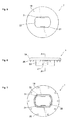
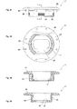
- Figs. 1 to 3 show the manner in which the fastening assembly 1, comprising a plurality of components, appears when used. A simple description shall now be given of the configuration of the fastening assembly 1 with reference to Figs. 1 to 3 .
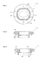
- Fig. 1 shows a first fastener 5 attached to an attachment hole 3 in a carpet 2 in order to reinforce the peripheral portion of the attachment hole 3, and a knob 6 attached to the first fastener 5 by pushing it into the first fastener 5 (i.e., into the knob base of the second carpet grommet thereof).
- the first fastener 5 comprises two components, namely, a first carpet grommet 7 and a second carpet grommet 9.
- a knob base 10 to which the knob 6 is coupled is integrally molded.
- These components, namely the knob 6, first carpet grommet 7 and second carpet grommet 9 (including the knob base 10), are formed of a plastic material.
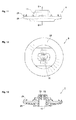
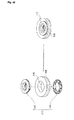
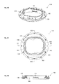
- Fig. 2 diagrams a second fastener 15 which is attached to an attachment hole 13 in a floor mat 11 to reinforce the peripheral portion of the attachment hole and which has a through hole 14 in its center.
- the second fastener 15 comprises two components, namely, a first mat grommet 17 and a second mat grommet 18.
- FIG. 3 shows the manner in which the floor mat 11 is secured to the carpet 2 by the combination of the knob 6 and first fastener 5 attached to the carpet 2, as shown in Fig. 1 , and the second fastener 15 attached to the floor mat 11, as shown in Fig. 2 .
- the carpet 2 and floor mat 11 are represented in the drawings as circular plate-shaped members, but the actual shapes thereof, in most cases, will not be the shapes indicated in Figs. 1 to 3 . It should be understood that the carpet 2, for example, will be in a sheet form that spreads over an automobile floor panel, while the floor mat 11 will be formed in a prescribed sheet form on which the vehicle occupant will place his or her feet.
- the knob 6 is inserted into a through hole in the knob base 10 formed integrally in the second carpet grommet 9 of the first fastener 5 that is configured by the first carpet grommet 7 and the second carpet grommet 9 and coupled to the first fastener.
- the first fastener 5 clamps the peripheral portion of the attachment hole 3 of the carpet 2 from the two sides of the carpet 2, that is, from its front surface and back surface, by the first carpet grommet 7 and the second carpet grommet 9.
- the first carpet grommet 7 is disposed at the front surface of the carpet 2
- the second carpet grommet 9 is disposed at the back surface of the carpet.
- the first carpet grommet 7 and the second carpet grommet 9 each have a flange that abuts against the peripheral portion of the attachment hole 3 of the carpet 2 and latching means capable of mutually coupling with the carpet 2 in a clamped state.
- the second fastener 15 comprises the first mat grommet 17 and the second mat grommet 18 which clamp the peripheral portion of the attachment hole 13 of the floor mat 11 from both sides.
- the first mat grommet 17 and second mat grommet 18, respectively, have a flange abutting against the peripheral portion of the attachment hole of the floor mat and latching means capable of coupling with the floor mat 11 in a clamped state.
- the first mat grommet 17 is disposed on the front surface of the floor mat 11, and the second mat grommet 18 is disposed on the back surface of the floor mat 11, respectively.
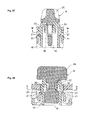
- the knob 6 When coupled to the knob base 10 provided in the second carpet grommet 9 of the first fastener 5, the knob 6 is capable of turning about its axis relative to the knob base 10 in order to assume an unlocked position, shown in Fig. 37 , or a locked position, shown in Fig. 38 . In the example shown, the knob 6 assumes the locked position by turning 90 degrees about its axis from the unlocked position.
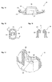
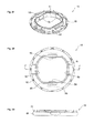
- the first fastener 5 shall now be described in detail with reference to Figs. 4 to 17 .
- Figs. 4 to 8 the first carpet grommet 7 of the first fastener 5 is shown.
- the first carpet grommet 7 there are a flange 19 that abuts against the peripheral portion of an attachment hole in the carpet 2 and latching parts 21 constituting latching means capable of working together with the second carpet grommet 9 to couple to the second carpet grommet 9 when the carpet 2 is in a clamped state.
- the latching parts 21 are formed in a pair on the inside surface of tubular part 23 that descends so as to encompass a through hole 22 formed in the flange 19.
- the latching parts 21 of the tubular part 23 are formed as elastic engagement pawls for latching to latching shoulders on base latching parts 27 of the knob base 10 formed in the second carpet grommet 9.
- the through hole 22 that extends from the flange 19 to the tubular part 23 is formed either in an oblong shape (an untrue circular shape wherein a true circle is cut by two sides that are in mutual opposition in the direction of its diameter), as illustrated, or in a rectangular shape, being formed in a shape for accepting the knob base 10 having a similarly shaped lateral cross-section.
- the height of the tubular part 23 is determined so as to match the thickness of the carpet 2 and accept the knob base 10.
- a plurality of sharp points or pins 25 is formed so that the first carpet grommet 7 does not shift on the carpet 2 or turn about its axis.
- the second carpet grommet 9 of the first fastener 5 is illustrated.
- the knob base 10 for coupling to the knob 6 is formed. Both the knob base 10 and knob 6 will be described in detail subsequently.
- a flange 26 that abuts against the peripheral portion of an attachment hole in the carpet 2 and a pair of base latching parts 27 comprising latching shoulders formed in the knob base 10 and constituting latching means capable of working together with the first carpet grommet 7 to couple the carpet, in a clamped state, to latching parts 21 in the first carpet grommet 7.
- the base latching parts 27 are formed in the tubular shaped knob base 10 which rises from the flange 26 so as to encompass the tubular part 23 of the through hole 14 and latch with the latching parts 21.
- a plurality of sharp points 29 is formed for sticking into the carpet 2 and preventing the first fastener 5 from shifting or turning about its axis.
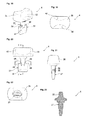
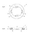
- the knob base 10 and knob 6 shall now be described in further detail with reference to Figs. 18 to 24 as well as to Figs. 9 to 17 .
- Figs. 9 to 17 the flange knob base 10 of the second carpet grommet 9 is illustrated.
- the knob base 10 overall is formed in a tubular shape having a rectangular or oblong lateral cross-section.
- the knob base 10 is formed in an untrue circular tubular shape in the lateral cross-section thereof, that is, in the shape of a true circle that is cut by two sides that are in mutual opposition in the direction of its diameter ( Fig. 15 ).
- the through hole 22 in the first carpet grommet 7 is formed in a shape resembling the lateral cross-sectional shape of the knob base 10, and in this way, the knob base 10 passes through the through hole 22 in the first carpet grommet 7 but is prevented from turning about its axis.
- the base latching parts 27 comprising latching shoulders are formed in the two outer surfaces in the knob base 10 that extend along the long sides of its lateral cross-sectional shape.
- the knob base 10 When the knob base 10 is inserted into the through hole 22 of the first carpet grommet 7, it latches with the latching parts 21 (comprising elastic latching pawls) of the first carpet grommet 7, whereupon the knob base 10 (and, by extension, the second carpet grommet 9 also) is coupled to the first carpet grommet 7. In this manner, merely by inserting the knob base 10 into the through hole 22 of the tubular part 23 of the first carpet grommet 7, the latching parts 21 latch with the base latching parts 27 and the first carpet grommet 7 and second carpet grommet 9 are coupled.
- the latching parts 21 comprising elastic latching pawls
- the knob base 10 has a base apex part 30 at its upper end.
- the knob 6 passes through the base apex part 30 and is inserted into the knob base 10.
- the base apex part 30 is formed as a plate-shaped body in which a long hole 31 is formed for accepting the shank of the knob 6.
- the long hole 31, as a knob-receiving hole, is sized to allow passage of the shank of the knob 6 in the direction of its long sides while not separating by being pulled out in the direction of its shorter sides.
- knob coupling latching pawls 33 are formed in a pair as latching means for coupling the knob 6 to the knob base 10 when the shank of the knob 6 is inserted into the knob base 10.
- the knob coupling latching pawls 33 as illustrated in Figs. 16 and 17 , comprise elastic latching pawls that descend a certain length from the base apex part 30. Because the space inside the knob base 10 is broad, the knob coupling latching pawls 33 are formed of sufficient size and strength to definitely latch onto the latching shoulders in the knob shank. Consequently, the strength by which the knob 6 latches to the knob base 10 is maintained even higher.
- the knob coupling latching pawls 33 are formed in the shape of plates that extend from the base apex part 30 of the knob base 10 of the tubular body toward the flange 26. Midway along the knob coupling latching pawls 33, in direction of its width, channels 34 which form the outer contour of the knob acceptance hole 31, are formed in the axial direction. In the channel 34 portion, the knob coupling latching pawls are formed as thin plates readily flexing outward when the knob shank 37 is inserted into the knob acceptance hole 31, facilitating insertion of the knob shank 37.
- the channels 34 that are oriented in the axial direction for accepting projections 39 formed in the latching shoulders of the shank of the second carpet grommet 9, are formed. These channels 34 are disposed at positions for receiving the projections 39 when the knob shank 37 is in the locked position. Consequently, completion of turning to the locked position can be felt by a sensation in one's fingers, also facilitating securing the locked position. More specifically, the projections 39 of the knob shank 37 and the channels 34 of the knob base 10 are formed in such shapes that, when the knob shank is turned to the locked position, the projections elastically fit into and mate with the channels 34 by the elasticity of the knob coupling latching pawls 33.
- the operator While manipulating the first fastener 5, the operator definitely feels the clicking sensation of having turned to the locked position that occurs at the completion of the securing operation.
- the projections of the knob shank and the channels 34 of the knob base 10 are shaped such that, in the mated state, the projections fill up the channels 34 in the lateral cross-section of the knob shank. Consequently, turning in the locked position is locked, and play in the turning direction can be prevented.
- This operation is illustrated in Fig. 39 from (A) to (C).
- the knob 6 is illustrated in Figs. 18 to 24 .
- the knob 6 has a knob head 35 that abuts against the peripheral portion of the through hole 14 (of the first mat grommet 17) of the second fastener 15 and the knob shank 37 which is inserted into the long hole 31 of the base apex part 30 of the knob base 10.
- latching shoulders 38 are formed as latching means for latching the knob coupling latching pawls 33 of the knob base 10.
- the projections 39 which protrude from the latching shoulders 38 in both the axial and radial directions, are formed.
- the projections 39 are sized to fit into and mate with the channels 34 of the knob coupling latching pawls 33 of the knob base 10.
- the projections 39 of the knob shank 37 and the channels 34 of the knob base 10 are shaped such that, when the knob shank 37 turns about its axis to the locked position ( Fig. 38 and Fig. 39 (C) ), the projections 39 elastically fit into and mate with the channels 34 by the elasticity of the channels 34. In this way, by manipulating the knob, the operator definitely feels the clicking sensation of having turned to the locked position that occurs at the completion of the securing operation.
- the projections 39 of the knob head 35 and the channels 34 of the knob base 10 are shaped such that the projections 39 will fill up the channels 34 in the lateral cross-section of the knob head 35 in the mated state. Consequently, turning in the locked position is locked, and play in the turning direction can be prevented.
- the knob shank 37 from the knob head 35 to the position of the latching shoulders 38, is formed in a rod shape (in a round shape in the example diagrammed), and from the latching shoulders 38 to the tip end (the lower end in Fig. 18 ), is formed as a plate-shaped body (part 41) having a rectangular lateral cross-section.
- the plate-shaped body portion 41 of the knob shank 37 is formed so that its width on the long sides of the rectangular lateral cross-section is equal to or slightly less than the length of the short sides of the rectangular lateral cross-section corresponding to the inside of the base latching parts 27.
- latching means are formed for coupling the knob 6 to the knob base 10 when the knob shank 37 is inserted into the knob base 10.
- These latching means are formed by the latching shoulders 38 that latch with the knob coupling latching pawls 33 of the knob base 10.
- the latching shoulders 38 may be of in any shape so long as they can latch with the knob coupling latching pawls 33 of the knob base 10. In the embodiment shown, they are formed by narrowing the width of the portion of the wide portion of the knob shank 37 corresponding to the positions at which the knob coupling latching pawls 33 can latch.
- knob coupling latching pawls 33 of the knob base 10 will latch on the latching shoulders 38 and the knob 6 will be coupled to the knob base 10.
- the knob shank 37 will be in the unlocked position, but the latching shoulders 38 will be partially latched to. Therefore, merely by inserting the knob shank 37 into the knob base 10 and thoroughly pushing it in just as it is, the knob 6 will be coupled to the knob base 10.
- the latching shoulders 38 will latch with the knob coupling latching pawls 33 over a wide surface area, and the knob 6 will be definitely coupled to the knob base 10. Furthermore, by that turning, the knob shank 37 is placed in the locked position. In the locked position, the coupling between the knob 6 and knob base 10 is maintained definitely.
- the projections 39 which protrude in the axial direction from the latching shoulders 38 toward the knob head 35, are formed. These projections 39 can fit into and mate with the channels 34 that, oriented in the axial direction, are formed in the knob coupling latching pawls 33 of the knob base 10. That is, when the knob shank 37 is turned to the locked position, the projections 39 fit into and mate with the channels 34. By this mating, the operator can feel that the knob shank 37 has been completely turned to the locked position by placing his or her fingers on the knob head 35. Moreover, by the mating of the projections 39 in the channels 34, the knob shank 37 is maintained in the locked position so the knob 6 can be fixed in the locked position. In the knob head 35, finger-gripping parts 42 are formed for turning the knob shank 37 about its axis.
- the second fastener 15 shall now be described in detail with reference to Figs. 25 to 35 .
- Figs. 25 to 30 the first mat grommet 17 of the second fastener 15 is illustrated.
- the first mat grommet 17 has a flange 43 that abuts against the peripheral portion of the attachment hole 13 in the floor mat 11 and multiply stepped latching parts 45 that can work together as latching means with the second mat grommet 18 to couple to the second mat grommet 18 with the floor mat 11 in a clamped state.
- the latching parts 45 are formed, on the outer surfaces of a tubular part 46 that descends from the flange 43, in the shape of grooves that run along the outer circumferential surface in multiple steps in the axial direction.
- a latching part 47 is formed, against which the head of the knob 6 abuts.
- This latching part 47 is formed as a plate-shaped body that extends from the inner wall surface of the tubular part 46 forming the through hole 14 toward the center.
- the long hole 14 through which the head of the knob 6 can pass is formed.
- This long hole 14 is shaped (an ellipse in the example illustrated) such that, when the knob 6 is in the unlocked position ( Fig. 40 ), the head of the knob can pass through, but when in the locked position ( Fig. 41 ), the head of the knob abuts against it and cannot pass through.
- the height of the tubular part 46 is determined to match the thickness of the floor mat 11.
- numerous sharp points 44 are formed which stick into the floor mat 11 to prevent the second fastener 15 from positionally shifting or turning about its axis.
- the knob latching part 47 against which the knob head 35 of the knob 6 abuts is formed.
- the knob latching part 47 is formed as a plate-shaped body that extends from the inner wall surface of the tubular part 46 forming the through hole 14 toward the center.
- the through hole 14 through which the knob head 35 can pass is formed.
- the through hole 14 is formed as a long hole sized such that, in the direction of its long sides, it will allow the knob head 35 to pass through, but in the direction of its short sides, the knob head 35 cannot separate by being pulled out.
- the second mat grommet 18 of the second fastener 15 is illustrated.
- the second mat grommet 18 has a flange 49 that abuts against the peripheral portion of the attachment hole 13 in the floor mat 11 and two pairs of latching parts 50 that as latching means can work with the first mat grommet 17 to couple to the latching parts 45 of the first mat grommet 17 with the floor mat 11 in a latched state.
- the latching parts 50 are formed in a tubular part 51 that rises slightly to encompass the tubular part 46 of the first mat grommet 17 and latch with the latching parts 45.
- first mat grommet 17 is disposed on the front surface of the floor mat 11, while the second mat grommet 18 is disposed on the back surface of the floor mat 11.
- the latching part 47 accepts the head of the knob 6 into its through hole 14.
- Fig. 36 (A) to (C) the state of the first fastener 5 being attached to the carpet 2 by the knob 6, by the operation shown in Fig. 1 , is illustrated.
- the first carpet grommet 7 of the first fastener 5 is disposed at the attachment hole 3 of the carpet 2
- the knob base 10 of the second carpet grommet 9 is disposed in a position for insertion into the attachment hole 3
- the tubular part 23 of the first carpet grommet 7 is pushed in so as to be accepted in the knob base 10.
- FIG. 36 (C) illustrates the manner in which the latching shoulders 38 of the knob shank 37 latch with the knob coupling latching pawls 33 of the knob base 10 and the manner in which the knob 6 is latched to the knob base 10 in the unlocked position.
- the second fastener 15 In order to secure the floor mat 11 to the carpet 2, the second fastener 15 must be attached to the floor mat 11, as illustrated in Fig. 2 .
- the tubular part 46 of the first mat grommet 17 is disposed at a position for insertion into the attachment hole 13 of the floor mat 11
- the tubular part 51 of the second mat grommet 18 is disposed at a position for insertion into the attachment hole 13
- the tubular part 46 of the first mat grommet 17 is pushed in so as to be accepted in the tubular part 51.
- the latching parts 45 of the tubular part 46 latch with the latching parts 50 of the tubular part 51, and the first mat grommet 17 and second mat grommet 18 are attached in a state wherein the floor mat 11 is clamped.
- the floor mat 11 to which the second fastener 15 has been attached is disposed on the carpet 2 to which the first fastener 5 and knob 6 are attached.
- the knob latching part 47 forming the through hole 14 in the first mat grommet 17 of the second fastener 15 is disposed so that the knob head 35 of the knob 6 that is in the unlocked position passes through the through hole 14; thus, the floor mat 11 to which the second fastener 15 has been attached is pressed, as is, against the carpet 2 to which the first fastener 5 and knob 6 have been attached.
- knob head 35 passes through the through hole 14 and comes out above the knob latching part 47, the operator manipulates the finger-gripping parts 42 of the knob head 35, turning the knob shank 37 by an angle of 90 degrees about its axis and moving the knob 6 from the unlocked position to the locked position.
- Fig. 38 and Fig. 39 (A) to (C) illustrate the manner in which the knob 6 is turned 90 degrees about the axis of the knob shank 37 to move the knob 6 from the unlocked position to the locked position.
- the knob 6 is turned 90 degrees about the axis of the knob shank 37, passing from the unlocked position diagrammed in Fig. 39 (A) to the intermediate state diagrammed in Fig. 39 (B) , the locked position diagrammed in Fig. 38 and Fig. 39 (C) is reached.
- channels 34 are formed in the axial direction for accepting the projections 39 formed in the latching shoulders 38 of the knob shank 37 of the second carpet grommet 9, which channels 34, when the knob 6 is in the locked position, are disposed at positions for accepting the projections 39. Consequently, it is possible to feel a clicking sensation with one's fingers when the turning to the locked position is complete; this is also useful in securing the locked position.
- the projections 39 of the knob shank 37 and the channels 34 of the knob base 10 are shaped so that in the mated state, in the lateral cross-section of the knob shank 37, the projections 39 fill up the channels 34 ( Fig. 39 (C) ).
- the width on the longer side of the rectangular lateral cross-section of the plate-shaped body part 41 of the knob shank 37 is formed so as to be a dimension equal to or slightly less than the length of the shorter sides of the rectangular lateral cross-section corresponding to the inside of the base latching parts 27 of the tubular part of the knob base 10.
- Fig. 40 shows the operation illustrated in Fig. 3 and the operation of moving the knob 6 to the locked position, such that the floor mat 11 is attached to the carpet 2 by the fastening assembly 1.
- the operation of combining a floor mat with a carpet is facilitated, separation after such combining can be prevented, the holding force of the knob 6 can be enhanced, and appearance after combining by the fastening assembly 1 is good.
- knob coupling latching pawls 33 for coupling the knob 6 to the knob base 10 can be formed in the spacious interior of the knob base 10, not only can the knob coupling latching pawls 33 be readily flexed, but the coupling strength for the knob 6 can be enhanced, play in the turning direction of the knob 6 can be prevented, and play in the locked position can be prevented; thus, separation by pulling on the floor mat 11 can be definitely prevented.
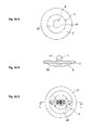
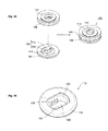
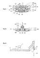
- FIG. 41 shows a first fastener 103 attached to an attachment hole in a carpet 102 to reinforce the peripheral portion of the attachment hole, with a through hole in its center, as well as a knob assembly 105 attached to the first fastener by being inserted into the through hole in the first fastener 103.
- Fig. 41 shows a first fastener 103 attached to an attachment hole in a carpet 102 to reinforce the peripheral portion of the attachment hole, with a through hole in its center, as well as a knob assembly 105 attached to the first fastener by being inserted into the through hole in the first fastener 103.
- Fig. 42 shows a second fastener 107 attached to an attachment hole in a floor mat 106 to reinforce the peripheral portion of the attachment hole, with a through hole in its center.
- Fig. 43 shows the manner in which the floor mat 106 is secured to the carpet 102 by the combination of the first fastener 103 and knob assembly 105 attached to the carpet 102 and by the second fastener 107 attached to the floor mat 106, as illustrated in Fig. 42 .
- the carpet 102 and the floor mat 106 are represented in the drawings as circular plate-shaped members, but their actual shapes in most cases will not be the shapes indicated in Figs. 41 to 43 . It should be understood that the carpet 102, for example, will be in a sheet form spreading over a floor panel, and that the floor mat 106 will be formed in a prescribed sheet form.
- the knob assembly 105 comprises a knob base 109 that is inserted into the through hole in the first fastener 103 and coupled to the fastening assembly 1 and a knob 110 coupled to the knob base 109.
- the first fastener 103 comprises a first carpet grommet 113 and a second carpet grommet 114 for clamping the peripheral portion of an attachment hole 111 in the carpet 102 from both sides.
- the first carpet grommet 113 and the second carpet grommet 114 respectively, have a flange that abuts against the peripheral portion of the attachment hole 111 in the carpet 102 and latching means capable of coupling the carpet 102 in a clamped state.
- the second fastener 107 comprises a first mat grommet 117 and a second mat grommet 118 for clamping the peripheral portion of an attachment hole 115 in the floor mat 106 from both sides.
- the first mat grommet 117 and the second mat grommet 118 respectively, have flanges that abut against the peripheral portion of an attachment hole in a floor mat, and latching means capable of coupling the floor mat 106 in a clamped state.
- the knob base 109, knob 110, first carpet grommet 113, second carpet grommet 114, first mat grommet 117 and second mat grommet 118, respectively, are each integrally molded of a plastic material. In Fig.
- the knob assembly 105 should preferably be attached to the first fastener 103 only when attaching the floor mat 106 to the carpet 102.
- the knob assembly 105 furthermore, when coupled to the first fastener 103, is such that the knob 110 can be turned about its axis relative to the knob base 109, to assume either the unlocked position illustrated in Fig. 80 or the locked position illustrated in Fig. 81 .
- first carpet grommet 113 of the first fastener 103 is illustrated.
- first carpet grommet 113 are a flange 119 that abuts against the peripheral portion of the attachment hole in the carpet 102 and latching parts 121 that, as latching means, can work together with the second carpet grommet 114 to couple to the second carpet grommet 114 with the carpet 102 in a clamped state.
- the latching parts 121 are formed in a pair at the outer surface of a tubular part 123 that descends so as to encompass a through hole 122 formed in the flange 119.
- the through hole 122 which extends from the knob 110 to the tubular part 123, is either of oblong shape (an untrue circular shape in which a true circle is cut by two sides in mutual opposition in the direction of its diameter), as shown, or of rectangular shape.
- the height of the tubular part 123 is determined to match the thickness of the carpet 102.
- a bottom surface 124 Fig. 49 ) be formed so as to maintain high strength in the tubular part 123.
- the second carpet grommet 114 of the first fastener 103 has a flange 126 that abuts against the peripheral portion of an attachment hole in the carpet 102 and a pair of latching parts 127 that, as latching means, can work together with the first carpet grommet 113 to couple with the latching parts 121 of the first carpet grommet 113 with the carpet 102 in a clamped state.
- the latching parts 127 are formed in a tubular part 129 that rises slightly to encompass the tubular part 123 of the first carpet grommet 113 and latch with the latching parts 121.
- first carpet grommet 113 configured in this manner, is disposed on the front surface of the carpet 102, while the second carpet grommet 114 is disposed on the back surface of the carpet 102.
- the knob assembly 105 is inserted from the first carpet grommet 113 into the second carpet grommet 114 and coupled to the first fastener 103.
- FIG. 54 to 64 the first mat grommet 117 of the second fastener 107 is illustrated.
- the first mat grommet 117 has a flange 131 that abuts against the peripheral portion of an attachment hole in the floor mat 106 and latching parts 133, and multiply stepped latching parts 133 that, as latching means, can work together with the second mat grommet 118 to couple to the second mat grommet 118 with the floor mat 106 in a clamped state.
- the latching parts 133 are formed on the outer surfaces of a tubular part 135 that descends to encompass a through hole 134 formed in the flange 131 in the shape of grooves that run along the outer circumferential surface in multiple steps in the axial direction.
- a latching part 137 is formed, against which the head of the knob 110 abuts.
- This latching part 137 is formed as a plate-shaped body that extends from the inner wall surface of the tubular part 135 forming the through hole 134 toward the center.
- the long hole 138 through which the head of the knob 110 can pass.
- This long hole 138 is shaped (as an ellipse in the example shown) such that, when the knob 110 is in the unlocked position ( Fig. 80 ), the knob head 153 can pass through, but when in the locked position ( Fig. 81 ), the knob head 153 abuts against it and cannot pass through.
- the height of the tubular part 135 is determined to match the thickness of the floor mat 106.
- the second mat grommet 118 of the second fastener 107 is illustrated.
- the second mat grommet 118 has a flange 139 that abuts against the peripheral portion of the attachment hole in the floor mat 106 and a pair of latching parts 141 that, as latching means, can work together with the first mat grommet 117 to latch with the latching parts 133 of the first mat grommet 117 with the floor mat 106 in a clamped state.
- the latching parts 141 are formed in a tubular part 142 that rises slightly to encompass the tubular part 135 of the first mat grommet 117 and latch with the latching parts 133.
- first mat grommet 117 configured in this manner, is disposed on the front side of the floor mat 106, and the second mat grommet 118 is disposed on the back side of the floor mat 106.
- the latching part 137 accepts the knob head 153 of the knob 110 of the knob assembly 105.
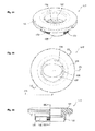
- knob base 109 of the knob assembly 105 is illustrated.
- the knob base 109 overall is tubular shaped with a lateral cross-section that is either rectangular or oblong.
- the knob base 109 is an untrue circular shape in which a true circle, in the lateral cross-section, is cut by two sides in mutual opposition in the direction of its diameter.
- the through hole 122 in the first fastener 103 (formed in the first carpet grommet 113) is shaped similar to the lateral cross-sectional shape of the knob base 109.
- a base flange 145 is formed to wind about the outer circumferential surface thereof at an intermediate position in the axial dimension of the knob base 109.
- the base flange 145 is sized to abut against the peripheral portion of the through hole 122 of the first carpet grommet 113 and not pass through the through hole 122, thus also aiding the coupling of the knob base 109 to the first carpet grommet 113.
- base latching pawls 146 are formed in the two outer surfaces running in the direction of the long sides of the lateral cross-sectional shape of the knob base.
- the base latching pawls 146 latch on the latching shoulders 125 of the first carpet grommet 113 to couple the knob base 109 to the first carpet grommet 113 (and, by extension, to the first fastener 103 as well).
- the base flange 145 of the fastening assembly 109 abuts against the flange 119 of the first carpet grommet 113; thus, the base latching pawls 146 latch on the latching shoulders 125 and couple the knob base 109 to the first carpet grommet 113 (and, by extension, to the first fastener 103 as well).
- the base latching pawls 146 of the knob base 109 comprise thin plate-shaped bodies that extend from the end of the knob base 109 (the lower end in Fig. 68 ) toward the base flange 145 to elastically protrude to the outside from the outer surfaces of the knob base 109 ( Figs. 66 and 70 ). Consequently, the force required for insertion into the through hole 122 (of the first carpet grommet 113) of the first fastener 103 is reduced. Upon insertion, the flange 119 coupled to the knob base 109 will be in the unlocked position ( Fig. 78, Fig. 79 ).
- the knob base 109 furthermore, has a base apex part 147 at its upper end, through which base apex part 147 the knob 110 is inserted into the knob base 109.
- the base apex part 147 is formed as a plate-shaped body in which a long hole 149 is formed for accepting the shank of the knob 110.
- the long hole 149 sized to allow the shank of the knob 110 to pass through in its long-side direction, but the knob 110 cannot be separated by being pulled out in the short-side direction.
- knob coupling latching pawls 150 that, as latching means, couple the knob 110 to the knob base 109 when the shank of the knob 110 is inserted into the knob base 109.
- the knob coupling latching pawls 150 are formed as elastic latching pawls that descend a certain length from the base apex part 147.
- channels 151 are formed in the axial direction for accepting projections formed in the latching shoulders of the shank of the knob 110, which channels 151 are disposed at positions for accepting the projections when the knob 110 is in the locked position.
- the knob coupling latching pawls 150 are formed to be of sufficient size and strength to definitely latch on the latching shoulders of the knob shank. Consequently, the strength by which the knob 110 is coupled to the knob base 109 is even greater.
- the knob coupling latching pawls 150 are formed in plate shapes that extend downward from the base apex part 147 of the tubular-body knob base 109.
- the knob coupling latching pawls 150 are formed as thin plates to easily flex outward when the shank of the knob 110 is inserted into the knob acceptance hole, thus facilitating insertion of the knob shank.
- the channels 151 of the knob coupling latching pawls 150 of the knob base 109 are in shapes that accept the projections formed in the latching shoulders of the shank of the knob 110 and are disposed at positions where those projections are accepted when the shank of the knob 110 is in the locked position. Consequently, one can feel a sensation in one's fingers when completing the turning to the locked position; this is also useful in securing the locked position. More specifically, the projections of the knob shank and the channels 151 of the knob base 109 are shaped such that, when the knob shank turns to the locked position, the projections elastically fit into and mate with the channels 151 according to the elasticity of the knob coupling latching pawls 150.
- the operator By manipulating the knob 110, the operator definitely feels the clicking sensation of completing the securing operation by having turned to the locked position.
- the projections of the knob shank and the channels 151 of the knob base 190 are shaped such that the projections will fit into and mate with the channels 151 to fill them up in the lateral cross-section of the knob shank in the mated state. Consequently, turning in the locked position is locked, and play in the turning direction can be prevented.
- the knob 110 of the knob assembly 105 is illustrated.
- the knob 110 has a knob head 153 that abuts against the peripheral portion of the through hole 134 in (the first mat grommet 117 of) the second fastener 107 and a knob shank 154 inserted into the long hole 149 in the base apex part 147 of the knob base 109.
- latching means are formed for latching to the knob base 109.
- the knob shank 154 is formed in a narrow plate shape that has a wide form for preventing the inward toppling of the base latching pawls 146 by the turning thereof by a prescribed angle (90 degrees in the embodiment shown) in the hollow interior of the knob base 109 and a thickness that does not prevent such inward toppling, and can turn about its axis to assume a unlocked position in which the inward toppling of the base latching pawls 146 is not prevented, and a locked position in which the inward toppling of the base latching pawls 146 is prevented.
- the knob shank 154 is a plate-shaped body that descends from the knob head 153 and is formed as a plate-shaped body of broad width with a size and a rectangular lateral cross-section so that it will pass through in the long side of the long hole 149 of the base apex part 147 of the knob base 109 but, in its shorter side will not separate by being pulled out.
- the knob head 153 is formed at the upper end (upper end in Fig. 72 ) of the knob shank 154, sized not to pass through the long hole 149 of the base apex part 147 of the knob base 109.
- finger-gripping parts 155 are formed to facilitate the operation of turning the knob shank 154 between the unlocked position and the locked position.
- latching means are formed for coupling the knob 110 to the knob base 109 when the knob shank 154 is inserted into the knob base 109.
- These latching means are constituted by latching shoulders 157 that latch with the knob coupling latching pawls 150 of the knob base 109.
- These latching shoulders 157 may be of any form as long as they can latch with the knob coupling latching pawls 150 of the knob base 109. In the embodiment shown, these latching shoulders are formed by narrowing the width of the portion, in the wide part of the knob shank 154, corresponding to the positions to latch to the knob coupling latching pawls 150.
- knob shank 154 when the knob shank 154 is inserted into the knob base 109 and thoroughly pushed in, the latching shoulders 157 of the knob base 109 will latch on the latching shoulders 157 and the knob 110 will be coupled to the knob base 109. Furthermore, immediately after pushing in, the knob shank 154 will be in the unlocked position, allowing the base latching pawls 146 to topple inwardly, but the knob coupling latching pawls 150 are formed in semicircular tubular shape by the formation of the channels 151 ( Fig. 69 ) and partially latch on the latching shoulders 157; thus, merely by inserting the knob shank into the knob base 109 and thoroughly pushing it in will the knob 110 be coupled to the knob base 109.
- the latching shoulders 157 will latch with the knob coupling latching pawls 150 over a wide surface area.
- the knob shank 154 engages so that its wide part prevents the base latching pawls 146 from toppling inward, and the locked position is assumed. In this locked position, the coupling of the knob 110 and knob base 109 is definitely maintained.
- projections 158 are formed which protrude from the latching shoulders 157 toward the knob head 153 in the axial direction and also in the radial direction. These projections 158 can fit in the axially directed channels 151 formed in the knob coupling latching pawls 150 of the knob base 109. More specifically, when the knob shank 154 is turned to the locked position, the wide part of the knob shank 154 engages so as to prevent the base latching pawls 146 from inwardly toppling, and the projections 158 fit into and mate with the channels 151.
- knob shank 154 has been completely turned to the locked position, which the operator knows by placing his or her fingers on the knob head 153.
- the knob shank 154 is maintained in the locked position, so the knob 110 can be fixed in the locked position.
- the knob assembly 105 is illustrated with the knob 110 combined with the knob base 109.
- the knob coupling latching pawls 150 of the knob base 109 latch on the latching shoulders 157, and the knob 110 is coupled to the knob base 109.
- the knob shank 154 will be in the unlocked position (indicated by solid lines in Fig. 78 ) in which the base latching pawls 146 are prevented from inwardly toppling, but the knob coupling latching pawls 150 are formed in semicircular tubular shapes ( Fig.
- the knob 110 will assume a state in which it is coupled to the knob base 109.
- the knob shank 154 will assume the locked position at which its wide part engages to prevent the base latching pawls 146 from inwardly toppling, as indicated by the dashed lines in Fig. 78 ; the latching shoulders 157 will latch with the knob coupling latching pawls 150 over a wide surface area, and the coupling of the knob 110 and knob base 109 will be definitely maintained.
- Figs. 79 to 81 and Figs. 41 to 43 The operation of securing the floor mat 106 to the carpet 102 using the fastening assembly 1 of such configuration shall now be described with reference to Figs. 79 to 81 and Figs. 41 to 43 .
- the knob assembly 105 in which the knob 110 has been coupled to the knob base 109, is inserted into the first carpet grommet 113 of the first fastener 103.
- Fig. 79 shows the situation immediately prior to that insertion. The operator holds the knob head 153 and inserts the knob assembly 105 into the first fastener 103.
- Fig. 80 shows the situation after insertion of the knob assembly 105.
- the base latching pawls 146 of the knob base 109 are formed to readily flex inward, the operator can easily conduct the insertion operation.
- the base latching pawls 146 latch on the latching shoulders 125 of the first carpet grommet 113, and the base flange 145 of the knob base 109 abuts against the flange 119 of the first carpet grommet 113; thus, the knob assembly 105 is definitely coupled to the first fastener 103.
- Fig. 80 shows the situation after insertion of the knob assembly 105.
- the knob assembly 105 is coupled to the first fastener 103, and by extension, the knob assembly 105 also is secured to the carpet 102. In this secured state, the knob 110 is in the locked position.
- the coupling between the knob 110 and knob base 109 depends on the latching between the latching shoulders 157 of the knob 110 and the knob coupling latching pawls 150 of the knob base 109.
- the knob shank 154 is wide and the latching shoulders 157 become wide, and because the knob coupling latching pawls 150 can be formed so as to be wide, play in the direction indicated by the arrow 159 in Fig. 80 can be minimized.
- the second fastener 107 comprising the first mat grommet 117 and the second mat grommet 118, is attached to the floor mat 106 as shown in Fig. 42 .
- This floor mat 106 is pushed in, as is, with the second fastener 107 of the floor mat 106 superimposed on the first fastener 103 of the carpet 102, with the knob head 153 of the knob 110 passing through the through hole 134 of the first mat grommet 117, as illustrated in Fig. 43 .
- the knob shank 154 of the knob 110 is turned by an angle of 90 degrees from the unlocked position to the locked position, the knob head 153 abuts the latching part 137 formed in the first mat grommet 117 of the second fastener 107 and pushes the second fastener 107 against the first fastener 103 in the axial direction.
- the wide part of the knob shank 154 of the knob 110 prevents the base flange 145 of the knob base 109 from inwardly toppling, and engagement between the base latching pawls 146 of the knob base 109 and the latching shoulders 125 of the first carpet grommet 113 that are the latching parts of the first fastener 103 is locked.
- the floor mat 106 is secured to the carpet 102 by the fastening assembly 101 as shown in Fig. 81 . Also, because the knob shank 154 is wide and engages the base latching pawls 146 of the knob base 109, play in the direction indicated by the arrow 161 in Fig. 81 can be minimized.
- Fig. 82 illustrates another embodiment.
- a first carpet grommet 113A in a first fastener 103A there are no latching shoulders for the base latching pawls 146 of the knob base 109 to latch on, but rather latching shoulders 162 on which the base latching pawls 146 of the knob base 109 latch are formed in a second carpet grommet 114A.
- the configuration is the same as that of the fastening assembly 1 previously described and therefore not further described here.
- the first carpet grommet 113A is disposed on the front surface of the carpet 102
- the second carpet grommet 114A is disposed on the back surface of the carpet 102
- the knob base 109 of the knob assembly 105 is inserted from the first carpet grommet 113A into the second carpet grommet 114A, whereupon coupling is effected to the first fastener 103A.
- the latching shoulders 162 that are the latching parts for latching to the knob base 109 of the knob assembly 105 are formed in the second carpet grommet 114A, and the knob assembly 105 is coupled to the first fastener 103A.
- the second carpet grommet 114A can strongly bear that force, which is an advantage.
- a floor mat 11A attached to the carpet 2 by the fastening assembly 1 is formed to have an attachment part 55 attached to a body panel 54. Even if the shape of the floor mat 11A is modified, the fastening assembly in accordance with the present invention can definitely secure the floor mat to the carpet.
Landscapes
- Engineering & Computer Science (AREA)
- Transportation (AREA)
- Mechanical Engineering (AREA)
- Passenger Equipment (AREA)
- Carpets (AREA)
Applications Claiming Priority (1)
| Application Number | Priority Date | Filing Date | Title |
|---|---|---|---|
| JP2009042044A JP5453699B2 (ja) | 2009-02-25 | 2009-02-25 | フロアマットをカーペットに固定する固定装置 |
Publications (2)
| Publication Number | Publication Date |
|---|---|
| EP2223637A1 true EP2223637A1 (de) | 2010-09-01 |
| EP2223637B1 EP2223637B1 (de) | 2012-05-09 |
Family
ID=42184157
Family Applications (1)
| Application Number | Title | Priority Date | Filing Date |
|---|---|---|---|
| EP10154335A Active EP2223637B1 (de) | 2009-02-25 | 2010-02-23 | Befestigungsanordnung zum Befestigen einer Fußmatte an einem Teppich |
Country Status (4)
| Country | Link |
|---|---|
| US (2) | US8375514B2 (de) |
| EP (1) | EP2223637B1 (de) |
| JP (1) | JP5453699B2 (de) |
| AT (1) | ATE556627T1 (de) |
Cited By (6)
| Publication number | Priority date | Publication date | Assignee | Title |
|---|---|---|---|---|
| US20100287748A1 (en) * | 2007-12-13 | 2010-11-18 | Illinois Tool Works Inc. | Fastener for fixing a mat to a carpet |
| CN102963286A (zh) * | 2011-08-30 | 2013-03-13 | 株式会社本田阿克塞斯 | 车辆用脚踏垫 |
| WO2013163514A2 (en) | 2012-04-27 | 2013-10-31 | Macneil Ip Llc | Two-piece vehicle floor cover retention device |
| WO2015112423A1 (en) * | 2014-01-22 | 2015-07-30 | Illinois Tool Works Inc. | Fixing device for mats in a vehicle |
| US11642996B2 (en) | 2021-10-07 | 2023-05-09 | Tarboy LLC | Vehicle floor covering system |
| WO2023112043A1 (en) * | 2021-12-13 | 2023-06-22 | Saurabh Kapoor | Anti-skid clip |
Families Citing this family (39)
| Publication number | Priority date | Publication date | Assignee | Title |
|---|---|---|---|---|
| US7945992B2 (en) * | 2007-12-17 | 2011-05-24 | Illinois Tool Works Inc. | Mat fastening system |
| DE102008061613A1 (de) * | 2008-12-11 | 2010-07-01 | Trw Automotive Electronics & Components Gmbh | Vorrichtung zur Befestigung einer Fahrzeuginnenverkleidung |
| US9248769B2 (en) * | 2010-08-05 | 2016-02-02 | Thermoflex Corporation | Carpet floor mat having plastic migrating prevention formation, and associated injection mold |
| JP5878312B2 (ja) * | 2011-07-21 | 2016-03-08 | 株式会社パイオラックス | マット用留め具の取付構造およびその留め具 |
| CN102411156B (zh) * | 2011-08-18 | 2014-07-02 | 德耀五金钮扣有限公司 | 打钮机出爪检测方法及应用该方法的专用设备 |
| JP5386568B2 (ja) * | 2011-11-25 | 2014-01-15 | 株式会社ホンダアクセス | 車両用フロアマット |
| JP5337210B2 (ja) * | 2011-08-30 | 2013-11-06 | 株式会社ホンダアクセス | 車両用フロアマット |
| JP5568065B2 (ja) * | 2011-08-30 | 2014-08-06 | 株式会社ホンダアクセス | 車両用フロアマット |
| JP5478573B2 (ja) * | 2011-08-30 | 2014-04-23 | 株式会社ホンダアクセス | 車両用フロアマット |
| JP5478592B2 (ja) * | 2011-11-24 | 2014-04-23 | 株式会社ホンダアクセス | 車両用フロアマット |
| US9016756B2 (en) | 2011-08-30 | 2015-04-28 | Honda Access Corp. | Vehicle floor mat |
| US9669745B2 (en) * | 2011-12-27 | 2017-06-06 | Piolax, Inc. | Mat fastener |
| US9422958B2 (en) | 2012-01-26 | 2016-08-23 | Empire Technology Development Llc | Sprung latch fastener |
| JP5931558B2 (ja) * | 2012-04-19 | 2016-06-08 | 永大化工株式会社 | 自動車フロアーマット用グロメット |
| US8690222B2 (en) * | 2012-05-25 | 2014-04-08 | Winfield Consumer Products, Inc. | Vehicle floor mat or floor liner kit having a clip |
| JP2014094655A (ja) * | 2012-11-09 | 2014-05-22 | Morito Co Ltd | フロアマット用ハトメ |
| KR101362056B1 (ko) | 2012-11-22 | 2014-02-12 | 주식회사 니프코코리아 | 차량용 보조매트 고정후크장치 |
| US8757698B1 (en) * | 2013-08-01 | 2014-06-24 | Ford Global Technologies, Llc | Floor mat system for vehicle |
| JP6263391B2 (ja) * | 2014-01-20 | 2018-01-17 | 株式会社ニフコ | クリップ |
| JP6335768B2 (ja) * | 2014-12-05 | 2018-05-30 | 日本Viam株式会社 | マット固定具 |
| CN107107804B (zh) * | 2014-12-26 | 2019-07-12 | 株式会社本田阿克塞斯 | 车辆用脚踏垫的固定构造以及对构件的固定构造 |
| US9199567B1 (en) | 2015-03-27 | 2015-12-01 | Macneil Ip Llc | Vehicle floor cover retention device with spiked base |
| US9610880B2 (en) | 2015-07-29 | 2017-04-04 | Macneil Ip Llc | Multi-vehicle retention grommet |
| US9994140B2 (en) * | 2015-04-03 | 2018-06-12 | Ford Global Technologies, Llc | Floor mat with integral heel blocker |
| JP1558615S (de) * | 2016-03-03 | 2016-09-12 | ||
| USD801248S1 (en) * | 2016-06-17 | 2017-10-31 | Hang Zhou Golden Sun Auto Parts Co., Ltd. | Vehicle floor mat |
| USD806620S1 (en) * | 2016-09-14 | 2018-01-02 | Fedex Corporate Services, Inc. | Wheel angle sensor adapter puck |
| USD806621S1 (en) * | 2016-09-14 | 2018-01-02 | Fedex Corporate Services, Inc. | Wheel angle sensor adapter housing |
| JP6952329B2 (ja) * | 2017-06-30 | 2021-10-20 | 株式会社岡田製作所 | フロアマットの固定具及びそれに用いるグロメット |
| US10723252B2 (en) | 2017-09-25 | 2020-07-28 | Thermoflex Corporation | Floor mat with integral grommet |
| US10245991B1 (en) * | 2017-12-06 | 2019-04-02 | Ford Global Technologies, Llc | Illuminated floor mat retention assembly |
| USD873754S1 (en) | 2018-09-11 | 2020-01-28 | Husky Liners, Inc. | Vehicle floor liner |
| US10946781B2 (en) | 2019-04-11 | 2021-03-16 | GM Global Technology Operations LLC | Vehicle floor mat retainer |
| IT201900010206A1 (it) * | 2019-06-27 | 2020-12-27 | Gianluca Ferrari | Congegno di chiusura a serraggio, multiuso, con piastra amovibile, intercambiabile e personalizzabile |
| USD962045S1 (en) * | 2019-12-26 | 2022-08-30 | Illinois Tool Works Inc. | Fastener |
| US11155189B2 (en) * | 2020-02-13 | 2021-10-26 | Honda Motor Co., Ltd. | Bumper assembly for vehicle seat |
| CN111609002B (zh) * | 2020-06-01 | 2021-06-11 | 安徽江淮汽车集团股份有限公司 | 地毯固定卡扣 |
| US11723438B2 (en) * | 2020-08-25 | 2023-08-15 | Illinois Tool Works Inc. | Adjustment buckle assembly |
| DE102023115601A1 (de) | 2023-06-15 | 2024-12-19 | Dr. Ing. H.C. F. Porsche Aktiengesellschaft | Adapter und Fixierungssystem zur Befestigung einer Fußmatte in einem Kraftfahrzeug |
Citations (5)
| Publication number | Priority date | Publication date | Assignee | Title |
|---|---|---|---|---|
| JPS6428151A (en) | 1987-07-20 | 1989-01-30 | Ishikawajima Harima Heavy Ind | Paper passing device |
| JPH0475208A (ja) * | 1990-07-17 | 1992-03-10 | Sumitomo Electric Ind Ltd | 無機絶縁電線 |
| JPH0475208B2 (de) | 1983-11-30 | 1992-11-30 | ||
| JP2004268731A (ja) | 2003-03-07 | 2004-09-30 | Japan Vilene Co Ltd | マット固定具、自動車用フロアマット及びその固定構造 |
| JP2008308085A (ja) | 2007-06-15 | 2008-12-25 | Nippon Pop Rivets & Fasteners Ltd | 自動車のマットの固定装置 |
Family Cites Families (17)
| Publication number | Priority date | Publication date | Assignee | Title |
|---|---|---|---|---|
| GB1136662A (en) * | 1966-04-23 | 1968-12-11 | Gkn Screws Fasteners Ltd | Improvements in or relating to quick release fasteners |
| JPH01281521A (ja) | 1988-05-09 | 1989-11-13 | Fanuc Ltd | データ送受信方法 |
| US4878792A (en) * | 1988-08-01 | 1989-11-07 | Illinois Tool Works, Inc. | Removable mat fastener |
| JP2512515Y2 (ja) | 1990-11-14 | 1996-10-02 | 日産自動車株式会社 | 脱着固定装置の取付構造 |
| JP2502933Y2 (ja) * | 1991-04-18 | 1996-06-26 | 株式会社ニフコ | 板状体用留め具 |
| US5362187A (en) * | 1992-11-03 | 1994-11-08 | Scalise Dane C | Releasable locking fastener |
| US5511919A (en) * | 1992-11-03 | 1996-04-30 | Scalise; Dane C. | Locking fastener |
| US5775859A (en) * | 1997-06-06 | 1998-07-07 | National Molding Corp. | Mat fastener |
| IT1314102B1 (it) * | 1999-12-02 | 2002-12-04 | I T W Fastex Italia Spa | Dispositivo di montaggio rapido di un tappettino su una moquettefissata sul pavimento di un veicolo. |
| US6735819B2 (en) * | 2000-12-15 | 2004-05-18 | David F. MacNeil | Hand mountable vehicle carpet affixation device |
| JP4493210B2 (ja) * | 2000-12-27 | 2010-06-30 | ポップリベット・ファスナー株式会社 | マット用固定具 |
| US6381806B1 (en) * | 2001-01-12 | 2002-05-07 | Nifty Products, Inc. | Retainer assembly for positive retention of floor mat |
| US6612795B2 (en) * | 2001-09-26 | 2003-09-02 | Illinois Tool Works Inc. | Quarter turn panel fastener |
| JP4837546B2 (ja) * | 2006-12-27 | 2011-12-14 | 株式会社パイオラックス | 部品の固定装置 |
| US7546661B2 (en) * | 2007-07-05 | 2009-06-16 | Connor Jr Mark A | Floor mat clip assembly |
| FR2925133B1 (fr) * | 2007-12-13 | 2013-06-28 | Itw De France | Attache de fixation d'un sur-tapis a un tapis |
| US7945992B2 (en) * | 2007-12-17 | 2011-05-24 | Illinois Tool Works Inc. | Mat fastening system |
-
2009
- 2009-02-25 JP JP2009042044A patent/JP5453699B2/ja active Active
-
2010
- 2010-02-23 AT AT10154335T patent/ATE556627T1/de active
- 2010-02-23 EP EP10154335A patent/EP2223637B1/de active Active
- 2010-02-24 US US12/711,786 patent/US8375514B2/en active Active
-
2013
- 2013-01-14 US US13/740,617 patent/US8756758B2/en active Active
Patent Citations (5)
| Publication number | Priority date | Publication date | Assignee | Title |
|---|---|---|---|---|
| JPH0475208B2 (de) | 1983-11-30 | 1992-11-30 | ||
| JPS6428151A (en) | 1987-07-20 | 1989-01-30 | Ishikawajima Harima Heavy Ind | Paper passing device |
| JPH0475208A (ja) * | 1990-07-17 | 1992-03-10 | Sumitomo Electric Ind Ltd | 無機絶縁電線 |
| JP2004268731A (ja) | 2003-03-07 | 2004-09-30 | Japan Vilene Co Ltd | マット固定具、自動車用フロアマット及びその固定構造 |
| JP2008308085A (ja) | 2007-06-15 | 2008-12-25 | Nippon Pop Rivets & Fasteners Ltd | 自動車のマットの固定装置 |
Cited By (8)
| Publication number | Priority date | Publication date | Assignee | Title |
|---|---|---|---|---|
| US20100287748A1 (en) * | 2007-12-13 | 2010-11-18 | Illinois Tool Works Inc. | Fastener for fixing a mat to a carpet |
| US8402605B2 (en) * | 2007-12-13 | 2013-03-26 | Illinois Tool Works Inc. | Fastener for fixing a mat to a carpet |
| CN102963286A (zh) * | 2011-08-30 | 2013-03-13 | 株式会社本田阿克塞斯 | 车辆用脚踏垫 |
| WO2013163514A2 (en) | 2012-04-27 | 2013-10-31 | Macneil Ip Llc | Two-piece vehicle floor cover retention device |
| EP2841301A4 (de) * | 2012-04-27 | 2015-12-23 | Macneil Ip Llc | Zweiteilige haltevorrichtung für fahrzeugbodenabdeckung |
| WO2015112423A1 (en) * | 2014-01-22 | 2015-07-30 | Illinois Tool Works Inc. | Fixing device for mats in a vehicle |
| US11642996B2 (en) | 2021-10-07 | 2023-05-09 | Tarboy LLC | Vehicle floor covering system |
| WO2023112043A1 (en) * | 2021-12-13 | 2023-06-22 | Saurabh Kapoor | Anti-skid clip |
Also Published As
| Publication number | Publication date |
|---|---|
| JP5453699B2 (ja) | 2014-03-26 |
| US8375514B2 (en) | 2013-02-19 |
| US20100212119A1 (en) | 2010-08-26 |
| ATE556627T1 (de) | 2012-05-15 |
| JP2010195179A (ja) | 2010-09-09 |
| US20130125341A1 (en) | 2013-05-23 |
| EP2223637B1 (de) | 2012-05-09 |
| US8756758B2 (en) | 2014-06-24 |
Similar Documents
| Publication | Publication Date | Title |
|---|---|---|
| EP2223637B1 (de) | Befestigungsanordnung zum Befestigen einer Fußmatte an einem Teppich | |
| US20100162537A1 (en) | Spacer clip | |
| US8007029B2 (en) | Attachment assembly for aerodynamic performance improvement cover | |
| US9956925B2 (en) | Attaching structure assembly for an attached component | |
| US20110260025A1 (en) | Carpet clamp | |
| JP4485281B2 (ja) | 留め具 | |
| DE102014118599A1 (de) | Elastisch gemittelte Riemensysteme und Verfahren | |
| TW201249686A (en) | Plastic clip | |
| US9726275B2 (en) | Shift lever of automotive transmission | |
| US20130322961A1 (en) | Coupling structure between shift lever and knob for vehicle | |
| CA2337462A1 (en) | Panel fastener | |
| US5289621A (en) | Plastic fastener | |
| JP4674292B2 (ja) | クリップ | |
| KR20080016734A (ko) | 클립 | |
| JPWO2019035273A1 (ja) | クリップ | |
| WO2017126449A1 (ja) | ステアリングホイール | |
| JP2010013013A (ja) | 車両のヒンジカバー部構造および車両のヒンジカバー部構造の組立方法 | |
| JP7120986B2 (ja) | 外装部材の接続構造 | |
| CN221213817U (zh) | 双层卡扣结构的汽车仪表台内饰件 | |
| JPH09217864A (ja) | 留め具 | |
| JP2002303309A (ja) | 止め具 | |
| JP2018202457A (ja) | パイプ加工方法およびパイプ加工用金型部材 | |
| JPS585123Y2 (ja) | 装飾板結合装置 | |
| JP2005162046A (ja) | 車載用電子制御部品の取付けブラケット | |
| JP2006044589A (ja) | 内装部品の結合構造 |
Legal Events
| Date | Code | Title | Description |
|---|---|---|---|
| PUAI | Public reference made under article 153(3) epc to a published international application that has entered the european phase |
Free format text: ORIGINAL CODE: 0009012 |
|
| AK | Designated contracting states |
Kind code of ref document: A1 Designated state(s): AT BE BG CH CY CZ DE DK EE ES FI FR GB GR HR HU IE IS IT LI LT LU LV MC MK MT NL NO PL PT RO SE SI SK SM TR |
|
| AX | Request for extension of the european patent |
Extension state: AL BA RS |
|
| 17P | Request for examination filed |
Effective date: 20110210 |
|
| RIC1 | Information provided on ipc code assigned before grant |
Ipc: A47G 27/04 20060101AFI20110311BHEP |
|
| GRAP | Despatch of communication of intention to grant a patent |
Free format text: ORIGINAL CODE: EPIDOSNIGR1 |
|
| GRAS | Grant fee paid |
Free format text: ORIGINAL CODE: EPIDOSNIGR3 |
|
| GRAA | (expected) grant |
Free format text: ORIGINAL CODE: 0009210 |
|
| AK | Designated contracting states |
Kind code of ref document: B1 Designated state(s): AT BE BG CH CY CZ DE DK EE ES FI FR GB GR HR HU IE IS IT LI LT LU LV MC MK MT NL NO PL PT RO SE SI SK SM TR |
|
| REG | Reference to a national code |
Ref country code: GB Ref legal event code: FG4D |
|
| REG | Reference to a national code |
Ref country code: AT Ref legal event code: REF Ref document number: 556627 Country of ref document: AT Kind code of ref document: T Effective date: 20120515 Ref country code: CH Ref legal event code: EP |
|
| REG | Reference to a national code |
Ref country code: IE Ref legal event code: FG4D |
|
| REG | Reference to a national code |
Ref country code: DE Ref legal event code: R096 Ref document number: 602010001332 Country of ref document: DE Effective date: 20120705 |
|
| REG | Reference to a national code |
Ref country code: NL Ref legal event code: VDEP Effective date: 20120509 |
|
| REG | Reference to a national code |
Ref country code: LT Ref legal event code: MG4D Effective date: 20120509 |
|
| PG25 | Lapsed in a contracting state [announced via postgrant information from national office to epo] |
Ref country code: PL Free format text: LAPSE BECAUSE OF FAILURE TO SUBMIT A TRANSLATION OF THE DESCRIPTION OR TO PAY THE FEE WITHIN THE PRESCRIBED TIME-LIMIT Effective date: 20120509 Ref country code: IS Free format text: LAPSE BECAUSE OF FAILURE TO SUBMIT A TRANSLATION OF THE DESCRIPTION OR TO PAY THE FEE WITHIN THE PRESCRIBED TIME-LIMIT Effective date: 20120909 Ref country code: CY Free format text: LAPSE BECAUSE OF FAILURE TO SUBMIT A TRANSLATION OF THE DESCRIPTION OR TO PAY THE FEE WITHIN THE PRESCRIBED TIME-LIMIT Effective date: 20120509 Ref country code: FI Free format text: LAPSE BECAUSE OF FAILURE TO SUBMIT A TRANSLATION OF THE DESCRIPTION OR TO PAY THE FEE WITHIN THE PRESCRIBED TIME-LIMIT Effective date: 20120509 Ref country code: LT Free format text: LAPSE BECAUSE OF FAILURE TO SUBMIT A TRANSLATION OF THE DESCRIPTION OR TO PAY THE FEE WITHIN THE PRESCRIBED TIME-LIMIT Effective date: 20120509 Ref country code: SE Free format text: LAPSE BECAUSE OF FAILURE TO SUBMIT A TRANSLATION OF THE DESCRIPTION OR TO PAY THE FEE WITHIN THE PRESCRIBED TIME-LIMIT Effective date: 20120509 Ref country code: NO Free format text: LAPSE BECAUSE OF FAILURE TO SUBMIT A TRANSLATION OF THE DESCRIPTION OR TO PAY THE FEE WITHIN THE PRESCRIBED TIME-LIMIT Effective date: 20120809 |
|
| REG | Reference to a national code |
Ref country code: AT Ref legal event code: MK05 Ref document number: 556627 Country of ref document: AT Kind code of ref document: T Effective date: 20120509 |
|
| PG25 | Lapsed in a contracting state [announced via postgrant information from national office to epo] |
Ref country code: GR Free format text: LAPSE BECAUSE OF FAILURE TO SUBMIT A TRANSLATION OF THE DESCRIPTION OR TO PAY THE FEE WITHIN THE PRESCRIBED TIME-LIMIT Effective date: 20120810 Ref country code: HR Free format text: LAPSE BECAUSE OF FAILURE TO SUBMIT A TRANSLATION OF THE DESCRIPTION OR TO PAY THE FEE WITHIN THE PRESCRIBED TIME-LIMIT Effective date: 20120509 Ref country code: PT Free format text: LAPSE BECAUSE OF FAILURE TO SUBMIT A TRANSLATION OF THE DESCRIPTION OR TO PAY THE FEE WITHIN THE PRESCRIBED TIME-LIMIT Effective date: 20120910 Ref country code: LV Free format text: LAPSE BECAUSE OF FAILURE TO SUBMIT A TRANSLATION OF THE DESCRIPTION OR TO PAY THE FEE WITHIN THE PRESCRIBED TIME-LIMIT Effective date: 20120509 Ref country code: SI Free format text: LAPSE BECAUSE OF FAILURE TO SUBMIT A TRANSLATION OF THE DESCRIPTION OR TO PAY THE FEE WITHIN THE PRESCRIBED TIME-LIMIT Effective date: 20120509 |
|
| PG25 | Lapsed in a contracting state [announced via postgrant information from national office to epo] |
Ref country code: BE Free format text: LAPSE BECAUSE OF FAILURE TO SUBMIT A TRANSLATION OF THE DESCRIPTION OR TO PAY THE FEE WITHIN THE PRESCRIBED TIME-LIMIT Effective date: 20120509 |
|
| PG25 | Lapsed in a contracting state [announced via postgrant information from national office to epo] |
Ref country code: SK Free format text: LAPSE BECAUSE OF FAILURE TO SUBMIT A TRANSLATION OF THE DESCRIPTION OR TO PAY THE FEE WITHIN THE PRESCRIBED TIME-LIMIT Effective date: 20120509 Ref country code: AT Free format text: LAPSE BECAUSE OF FAILURE TO SUBMIT A TRANSLATION OF THE DESCRIPTION OR TO PAY THE FEE WITHIN THE PRESCRIBED TIME-LIMIT Effective date: 20120509 Ref country code: RO Free format text: LAPSE BECAUSE OF FAILURE TO SUBMIT A TRANSLATION OF THE DESCRIPTION OR TO PAY THE FEE WITHIN THE PRESCRIBED TIME-LIMIT Effective date: 20120509 Ref country code: CZ Free format text: LAPSE BECAUSE OF FAILURE TO SUBMIT A TRANSLATION OF THE DESCRIPTION OR TO PAY THE FEE WITHIN THE PRESCRIBED TIME-LIMIT Effective date: 20120509 Ref country code: NL Free format text: LAPSE BECAUSE OF FAILURE TO SUBMIT A TRANSLATION OF THE DESCRIPTION OR TO PAY THE FEE WITHIN THE PRESCRIBED TIME-LIMIT Effective date: 20120509 Ref country code: DK Free format text: LAPSE BECAUSE OF FAILURE TO SUBMIT A TRANSLATION OF THE DESCRIPTION OR TO PAY THE FEE WITHIN THE PRESCRIBED TIME-LIMIT Effective date: 20120509 Ref country code: EE Free format text: LAPSE BECAUSE OF FAILURE TO SUBMIT A TRANSLATION OF THE DESCRIPTION OR TO PAY THE FEE WITHIN THE PRESCRIBED TIME-LIMIT Effective date: 20120509 |
|
| PG25 | Lapsed in a contracting state [announced via postgrant information from national office to epo] |
Ref country code: IT Free format text: LAPSE BECAUSE OF FAILURE TO SUBMIT A TRANSLATION OF THE DESCRIPTION OR TO PAY THE FEE WITHIN THE PRESCRIBED TIME-LIMIT Effective date: 20120509 |
|
| PLBE | No opposition filed within time limit |
Free format text: ORIGINAL CODE: 0009261 |
|
| STAA | Information on the status of an ep patent application or granted ep patent |
Free format text: STATUS: NO OPPOSITION FILED WITHIN TIME LIMIT |
|
| 26N | No opposition filed |
Effective date: 20130212 |
|
| PG25 | Lapsed in a contracting state [announced via postgrant information from national office to epo] |
Ref country code: ES Free format text: LAPSE BECAUSE OF FAILURE TO SUBMIT A TRANSLATION OF THE DESCRIPTION OR TO PAY THE FEE WITHIN THE PRESCRIBED TIME-LIMIT Effective date: 20120820 |
|
| REG | Reference to a national code |
Ref country code: DE Ref legal event code: R097 Ref document number: 602010001332 Country of ref document: DE Effective date: 20130212 |
|
| PG25 | Lapsed in a contracting state [announced via postgrant information from national office to epo] |
Ref country code: BG Free format text: LAPSE BECAUSE OF FAILURE TO SUBMIT A TRANSLATION OF THE DESCRIPTION OR TO PAY THE FEE WITHIN THE PRESCRIBED TIME-LIMIT Effective date: 20120809 |
|
| REG | Reference to a national code |
Ref country code: HU Ref legal event code: AG4A Ref document number: E015831 Country of ref document: HU |
|
| PG25 | Lapsed in a contracting state [announced via postgrant information from national office to epo] |
Ref country code: MC Free format text: LAPSE BECAUSE OF NON-PAYMENT OF DUE FEES Effective date: 20130228 |
|
| PG25 | Lapsed in a contracting state [announced via postgrant information from national office to epo] |
Ref country code: DE Free format text: LAPSE BECAUSE OF NON-PAYMENT OF DUE FEES Effective date: 20130903 |
|
| REG | Reference to a national code |
Ref country code: FR Ref legal event code: ST Effective date: 20131031 |
|
| REG | Reference to a national code |
Ref country code: IE Ref legal event code: MM4A |
|
| REG | Reference to a national code |
Ref country code: DE Ref legal event code: R119 Ref document number: 602010001332 Country of ref document: DE Effective date: 20130903 |
|
| PG25 | Lapsed in a contracting state [announced via postgrant information from national office to epo] |
Ref country code: FR Free format text: LAPSE BECAUSE OF NON-PAYMENT OF DUE FEES Effective date: 20130228 Ref country code: IE Free format text: LAPSE BECAUSE OF NON-PAYMENT OF DUE FEES Effective date: 20130223 |
|
| PG25 | Lapsed in a contracting state [announced via postgrant information from national office to epo] |
Ref country code: MT Free format text: LAPSE BECAUSE OF FAILURE TO SUBMIT A TRANSLATION OF THE DESCRIPTION OR TO PAY THE FEE WITHIN THE PRESCRIBED TIME-LIMIT Effective date: 20120509 |
|
| REG | Reference to a national code |
Ref country code: CH Ref legal event code: PL |
|
| GBPC | Gb: european patent ceased through non-payment of renewal fee |
Effective date: 20140223 |
|
| PG25 | Lapsed in a contracting state [announced via postgrant information from national office to epo] |
Ref country code: CH Free format text: LAPSE BECAUSE OF NON-PAYMENT OF DUE FEES Effective date: 20140228 Ref country code: LI Free format text: LAPSE BECAUSE OF NON-PAYMENT OF DUE FEES Effective date: 20140228 |
|
| PG25 | Lapsed in a contracting state [announced via postgrant information from national office to epo] |
Ref country code: GB Free format text: LAPSE BECAUSE OF NON-PAYMENT OF DUE FEES Effective date: 20140223 |
|
| PG25 | Lapsed in a contracting state [announced via postgrant information from national office to epo] |
Ref country code: SM Free format text: LAPSE BECAUSE OF FAILURE TO SUBMIT A TRANSLATION OF THE DESCRIPTION OR TO PAY THE FEE WITHIN THE PRESCRIBED TIME-LIMIT Effective date: 20120509 |
|
| PG25 | Lapsed in a contracting state [announced via postgrant information from national office to epo] |
Ref country code: TR Free format text: LAPSE BECAUSE OF FAILURE TO SUBMIT A TRANSLATION OF THE DESCRIPTION OR TO PAY THE FEE WITHIN THE PRESCRIBED TIME-LIMIT Effective date: 20120509 |
|
| PG25 | Lapsed in a contracting state [announced via postgrant information from national office to epo] |
Ref country code: LU Free format text: LAPSE BECAUSE OF NON-PAYMENT OF DUE FEES Effective date: 20130223 Ref country code: MK Free format text: LAPSE BECAUSE OF FAILURE TO SUBMIT A TRANSLATION OF THE DESCRIPTION OR TO PAY THE FEE WITHIN THE PRESCRIBED TIME-LIMIT Effective date: 20120509 |
|
| PGFP | Annual fee paid to national office [announced via postgrant information from national office to epo] |
Ref country code: HU Payment date: 20250218 Year of fee payment: 16 |