EP2222903B1 - Centrifugal solution spun nanofiber process - Google Patents
Centrifugal solution spun nanofiber process Download PDFInfo
- Publication number
- EP2222903B1 EP2222903B1 EP08862609.8A EP08862609A EP2222903B1 EP 2222903 B1 EP2222903 B1 EP 2222903B1 EP 08862609 A EP08862609 A EP 08862609A EP 2222903 B1 EP2222903 B1 EP 2222903B1
- Authority
- EP
- European Patent Office
- Prior art keywords
- spin disk
- spinning solution
- nanofibers
- collector
- disk
- Prior art date
- Legal status (The legal status is an assumption and is not a legal conclusion. Google has not performed a legal analysis and makes no representation as to the accuracy of the status listed.)
- Active
Links
- 239000002121 nanofiber Substances 0.000 title claims description 64
- 238000000034 method Methods 0.000 title claims description 28
- 238000009987 spinning Methods 0.000 claims description 51
- 239000000835 fiber Substances 0.000 claims description 38
- 239000002904 solvent Substances 0.000 claims description 20
- 229920000642 polymer Polymers 0.000 claims description 15
- 238000007493 shaping process Methods 0.000 claims description 12
- 230000005684 electric field Effects 0.000 claims description 10
- 239000012530 fluid Substances 0.000 claims description 8
- 239000007789 gas Substances 0.000 claims description 8
- IJGRMHOSHXDMSA-UHFFFAOYSA-N Atomic nitrogen Chemical compound N#N IJGRMHOSHXDMSA-UHFFFAOYSA-N 0.000 claims description 4
- 230000008014 freezing Effects 0.000 claims description 4
- 238000007710 freezing Methods 0.000 claims description 4
- 229920001634 Copolyester Polymers 0.000 claims description 2
- 229920000106 Liquid crystal polymer Polymers 0.000 claims description 2
- 239000004977 Liquid-crystal polymers (LCPs) Substances 0.000 claims description 2
- 239000004952 Polyamide Substances 0.000 claims description 2
- 239000004793 Polystyrene Substances 0.000 claims description 2
- 229920003235 aromatic polyamide Polymers 0.000 claims description 2
- 229920013724 bio-based polymer Polymers 0.000 claims description 2
- 229920002988 biodegradable polymer Polymers 0.000 claims description 2
- 239000004621 biodegradable polymer Substances 0.000 claims description 2
- 229920001577 copolymer Polymers 0.000 claims description 2
- 238000007599 discharging Methods 0.000 claims description 2
- 229920002313 fluoropolymer Polymers 0.000 claims description 2
- 239000004811 fluoropolymer Substances 0.000 claims description 2
- 229920005615 natural polymer Polymers 0.000 claims description 2
- 229910052757 nitrogen Inorganic materials 0.000 claims description 2
- 229920000233 poly(alkylene oxides) Polymers 0.000 claims description 2
- 229920001281 polyalkylene Polymers 0.000 claims description 2
- 229920002647 polyamide Polymers 0.000 claims description 2
- 229920000728 polyester Polymers 0.000 claims description 2
- 229920000193 polymethacrylate Polymers 0.000 claims description 2
- 229920002223 polystyrene Polymers 0.000 claims description 2
- 229920002635 polyurethane Polymers 0.000 claims description 2
- 239000004814 polyurethane Substances 0.000 claims description 2
- 102000004169 proteins and genes Human genes 0.000 claims description 2
- 108090000623 proteins and genes Proteins 0.000 claims description 2
- 229920001169 thermoplastic Polymers 0.000 claims description 2
- 229920006163 vinyl copolymer Polymers 0.000 claims description 2
- 229920002554 vinyl polymer Polymers 0.000 claims description 2
- 229920000098 polyolefin Polymers 0.000 claims 1
- 229920003171 Poly (ethylene oxide) Polymers 0.000 description 11
- 238000001878 scanning electron micrograph Methods 0.000 description 11
- XAGFODPZIPBFFR-UHFFFAOYSA-N aluminium Chemical compound [Al] XAGFODPZIPBFFR-UHFFFAOYSA-N 0.000 description 7
- 229910052782 aluminium Inorganic materials 0.000 description 7
- 239000011888 foil Substances 0.000 description 7
- 230000000052 comparative effect Effects 0.000 description 6
- -1 poly(ethylene oxide) Polymers 0.000 description 5
- XLYOFNOQVPJJNP-UHFFFAOYSA-N water Substances O XLYOFNOQVPJJNP-UHFFFAOYSA-N 0.000 description 4
- 239000003973 paint Substances 0.000 description 3
- 229920002451 polyvinyl alcohol Polymers 0.000 description 3
- 230000004888 barrier function Effects 0.000 description 2
- 239000011248 coating agent Substances 0.000 description 2
- 238000000576 coating method Methods 0.000 description 2
- 239000002131 composite material Substances 0.000 description 2
- 230000007547 defect Effects 0.000 description 2
- 239000000463 material Substances 0.000 description 2
- 238000010998 test method Methods 0.000 description 2
- 238000009834 vaporization Methods 0.000 description 2
- 230000008016 vaporization Effects 0.000 description 2
- 230000015572 biosynthetic process Effects 0.000 description 1
- 239000003990 capacitor Substances 0.000 description 1
- 230000000694 effects Effects 0.000 description 1
- 238000001523 electrospinning Methods 0.000 description 1
- 238000005516 engineering process Methods 0.000 description 1
- 239000004744 fabric Substances 0.000 description 1
- 238000001914 filtration Methods 0.000 description 1
- 239000007788 liquid Substances 0.000 description 1
- 238000004519 manufacturing process Methods 0.000 description 1
- 239000011295 pitch Substances 0.000 description 1
- 230000001681 protective effect Effects 0.000 description 1
- GOZDTZWAMGHLDY-UHFFFAOYSA-L sodium picosulfate Chemical compound [Na+].[Na+].C1=CC(OS(=O)(=O)[O-])=CC=C1C(C=1N=CC=CC=1)C1=CC=C(OS([O-])(=O)=O)C=C1 GOZDTZWAMGHLDY-UHFFFAOYSA-L 0.000 description 1
Images


Classifications
-
- D—TEXTILES; PAPER
- D01—NATURAL OR MAN-MADE THREADS OR FIBRES; SPINNING
- D01D—MECHANICAL METHODS OR APPARATUS IN THE MANUFACTURE OF ARTIFICIAL FILAMENTS, THREADS, FIBRES, BRISTLES OR RIBBONS
- D01D5/00—Formation of filaments, threads, or the like
- D01D5/18—Formation of filaments, threads, or the like by means of rotating spinnerets
-
- B—PERFORMING OPERATIONS; TRANSPORTING
- B82—NANOTECHNOLOGY
- B82Y—SPECIFIC USES OR APPLICATIONS OF NANOSTRUCTURES; MEASUREMENT OR ANALYSIS OF NANOSTRUCTURES; MANUFACTURE OR TREATMENT OF NANOSTRUCTURES
- B82Y30/00—Nanotechnology for materials or surface science, e.g. nanocomposites
-
- D—TEXTILES; PAPER
- D01—NATURAL OR MAN-MADE THREADS OR FIBRES; SPINNING
- D01D—MECHANICAL METHODS OR APPARATUS IN THE MANUFACTURE OF ARTIFICIAL FILAMENTS, THREADS, FIBRES, BRISTLES OR RIBBONS
- D01D5/00—Formation of filaments, threads, or the like
- D01D5/0007—Electro-spinning
- D01D5/0061—Electro-spinning characterised by the electro-spinning apparatus
- D01D5/0069—Electro-spinning characterised by the electro-spinning apparatus characterised by the spinning section, e.g. capillary tube, protrusion or pin
-
- B—PERFORMING OPERATIONS; TRANSPORTING
- B82—NANOTECHNOLOGY
- B82Y—SPECIFIC USES OR APPLICATIONS OF NANOSTRUCTURES; MEASUREMENT OR ANALYSIS OF NANOSTRUCTURES; MANUFACTURE OR TREATMENT OF NANOSTRUCTURES
- B82Y40/00—Manufacture or treatment of nanostructures
-
- D—TEXTILES; PAPER
- D01—NATURAL OR MAN-MADE THREADS OR FIBRES; SPINNING
- D01D—MECHANICAL METHODS OR APPARATUS IN THE MANUFACTURE OF ARTIFICIAL FILAMENTS, THREADS, FIBRES, BRISTLES OR RIBBONS
- D01D5/00—Formation of filaments, threads, or the like
- D01D5/0007—Electro-spinning
- D01D5/0015—Electro-spinning characterised by the initial state of the material
- D01D5/003—Electro-spinning characterised by the initial state of the material the material being a polymer solution or dispersion
-
- D—TEXTILES; PAPER
- D01—NATURAL OR MAN-MADE THREADS OR FIBRES; SPINNING
- D01D—MECHANICAL METHODS OR APPARATUS IN THE MANUFACTURE OF ARTIFICIAL FILAMENTS, THREADS, FIBRES, BRISTLES OR RIBBONS
- D01D5/00—Formation of filaments, threads, or the like
- D01D5/12—Stretch-spinning methods
- D01D5/14—Stretch-spinning methods with flowing liquid or gaseous stretching media, e.g. solution-blowing
Definitions
- nanofibers can be made and collected into a fibrous web useful for selective barrier end uses such as filters, battery separators, and breathable medical gowns.
- Rotary sprayers used in conjunction with a shaping fluid and an electrical field are useful in atomizing paint for coating a target device.
- the centrifugal force supplied by the rotary sprayers produces enough shear to cause the paint to become atomized and the shaping fluid and electrical field draw the atomized paint to the target device.
- This process has been optimized for the production of atomized droplets. Defects occur when too many atomized droplets agglomerate into larger entities.
- the prior art teaches toward making atomized droplets and not larger entities.
- the present invention provides a high throughput process to make nanofibers and uniform webs by the use of a high speed rotating spin disk.
- the present invention is directed to a nanofiber forming process comprising the steps of supplying a spinning solution having at least one polymer dissolved in at least one solvent at a temperature between about 100°C and the freezing point of the solvent to a rotating spin disk with a rotational speed between about 4,000 rpm and about 100,000 rpm, the spin disk having a flat surface and a forward surface discharge edge; providing a porous collector and a vacuum device to pull vaporized solvent away from from the nanofibers and pin the nanofibers to the collector; issuing the spinning solution from the spin disk along the flat surface so as to fully wet the flat surface of the spin disk and to distribute the spinning solution as a film toward the forward surface of the discharge edge of the spin disk, and forming separate fibrous streams from the spinning solution while the solvent vaporizes to produce polymeric nanofibers.
- the present invention as specified above is further directed to a nanofiber forming process comprising the steps of supplying a spinning solution having at least one polymer dissolved in at least one solvent at a temperature between about 100°C and the freezing point of the solvent to a rotating spin disk with a rotational speed between about 4,000 rpm and about 100,000 rpm, the spin disk having a flat surface and a forward surface discharge edge wherein the spin disk has a concave region relative to the flat surface concentrically located within 40% of the radial distance to the center of the spin disk that defines a reservoir and issuing the spinning solution to the reservoir, issuing the spinning solution from the spin disk along the flat surface so as to fully wet the flat surface of the spin disk and to distribute the spinning solution as a film toward the forward surface of the discharge edge of the spin disk, and forming separate fibrous streams from the spinning solution while the solvent vaporizes to produce polymeric nanofibers.
- the invention relates to a process for forming nanofibers from a spinning solution utilizing a high speed rotating spin disk having a flat surface.
- nanofibers refers to fibers having diameters varying from a few tens of nanometers up to several hundred nanometers, but generally less than about one micrometer, even less than about 0.8 micrometer, and even less than about 0.5 micrometer.
- the solution spun fabrics and webs of the present invention include at least one layer of polymeric nanofibers.
- the nanofibers have average fiber diameters of less than about 1 ⁇ m, preferably between about 0.1 ⁇ m and about 1 ⁇ m, and high enough basis weights to satisfy a variety of commercial end-uses, such as for air/liquid filtration media, battery and capacitor separators, protective apparel and the like.
- the spinning solution comprises at least one polymer dissolved in at least one solvent. Any fiber forming polymer able to dissolve in a solvent that can be vaporized can be used. Suitable polymers include polyalkylene oxides, poly(meth)acrylates, polystyrene based polymers and copolymers, vinyl polymers and copolymers, fluoropolymers, polyesters and copolyesters, polyurethanes, polyalkylenes, polyamides, polyaramids, thermoplastic polymers, liquid crystal polymers, engineering polymers, biodegradable polymers, bio-based polymers, natural polymers, and protein polymers. Generally, a spinning solution with a viscosity from about 10 cP to about 100,000 cP, more advantageously from about 100 cP to about 75,000 cP and most advantageously from about 1,000 cP to about 50,000 cP is useful.
- FIG. 1 is an illustration of a rotating spin disk suitable for forming nanofibers from the spinning solution.
- the rotating spin disk can be used in the spinneret portion of a rotary sprayer apparatus or centrifugal spinning apparatus (not shown).
- the rotating spin disk 10 having a flat surface 11 and a forward surface discharge edge 12 is mounted on a drive shaft 13 which is connected to a high speed motor (not shown).
- a spinning solution is prepared by dissolving at least one polymer in at least one solvent.
- the spinning solution at a temperature between about 100°C and the freezing point of the solvent is pumped through a supply tube 14 running coaxially with drive shaft 13 and in close proximity to the center of spin disk 10 on the side of spin disk 10 opposite the side attached to drive shaft 13.
- the throughput rate of the solution is from about 1 cc/min to about 500 cc/min.
- a rotational speed of the spin disk 10 is between about 4,000 rpm and about 100,000 rpm, more advantageously between about 6,000 rpm and about 100,000 rpm and most advantageously between about 8,000 rpm and about 100,000 rpm.
- the forward surface discharge edge 12 can be sharp or rounded and can include serrations or dividing ridges.
- the rotation speed of the spin disk 10 propels the spinning solution along flat surface 11 and past the forward surface discharge edge 12 to form separate fibrous streams, which are thrown off the discharge edge by centrifugal force. Simultaneously, the solvent vaporizes until nanofibers of the invention are formed. The nanofibers are collected on a collector (not shown) to form a fibrous web.
- Figure 2 shows the spinning solution being delivered to spin disk 20 via a coaxial hollow portion of drive shaft 23.
- the spinning solution can either exit the hollow portion of drive shaft 23 via an outlet 24 located at the center of spin disk 20 on the side opposite the side that is attached to drive shaft 23 along flat surface 11 and past the forward surface discharge edge 12 or via one or more outlets 25 (one is shown) preferably symmetrically positioned around and through drive shaft 23 adjacent spin disk 20 along flat surface 11' and past the forward surface discharge edge 12' or via both types of outlets.
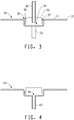
- FIG 3 is an illustration of another embodiment of a rotating spin disk suitable for forming nanofibers from the spinning solution.
- the rotating spin disk 30 having a flat surface 11 and a forward surface discharge edge 12 is mounted on a drive shaft 33 which is connected to a high speed motor (not shown).
- Spin disk 30 has a concave region 34 relative to the flat surface concentrically located within 40% of the radial distance to the center of the spin disk 30 located on the side opposite of the side attached to drive shaft 33.
- This concave region 34 defines a reservoir for receiving the spinning solution.
- the reservoir can be encapsulated with a housing 35 with a coaxial inlet for receiving the spinning solution via spinning supply tube 36 and one or more outlets 37 preferably symmetrically positioned around housing 35 for discharging the spinning solution.
- a gap 38 can exist between the outlet 37 and a perpendicular portion of the flat surface of the spin disk 30 that defines the concave region.
- a spin disk inner edge 39 is located where the perpendicular portion of the spin disk meets the flat surface 11 of the spin disk.
- the spin disk inner edge 39 can be rounded or sharp.
- Figure 4 is similar to Figure 3 except Figure 4 shows the spinning solution being delivered to spin disk 40 via a coaxial hollow portion of drive shaft 43.
- the spinning solution can exit the hollow portion of drive shaft 43 via an outlet 44 located at the center of spin disk 40 on the side opposite the side that is attached to drive shaft 43.
- Figure 5 is similar to Figure 4 except Figure 5 shows the spinning solution being delivered to spin disk 50 via a coaxial hollow portion of drive shaft 53 which is located on the same side of spin disk 50 as the side with concave portion 34.
- the spinning solution can exit the hollow portion of drive shaft 53 via one or more preferably symmetrical outlets 54 through drive shaft 53 adjacent spin disk 50.
- Figure 6 is similar to Figure 5 except Figure 6 shows the spinning solution being delivered to spin disk 60 via a supply tube 66 passing through housing 35 at inlet 67.
- Spin disk 60 is attached to drive shaft 63 which is located on the same side of spin disk 60 as the side with concave portion 34.
- shaping fluid can flow around the spin disks to direct the spinning solution away from the spin disks.
- the fluid can be delivered via nozzles positioned in an annular configuration to the rotating spin disk.
- the shaping fluid can be a gas.
- gases and at various temperatures can be used to decrease or to increase the rate of solvent vaporization to affect the type of nanofiber that is produced.
- the shaping gas can be heated or cooled in order to optimize the rate of solvent vaporization. Suitable gases to use are air and nitrogen, but any other gas which does not detrimentally affect the formation of nanofibers can be used.
- an electrical field can be added to the process.
- a voltage potential can be added between the spin disk and the collector. Either the spin disk or the collector can be charged with the other component substantially grounded or they can both be charged so long as a voltage potential exists between them.
- an electrode can be positioned between the spin disk and the collector wherein the electrode is charged so that a voltage potential is created between the electrode and the spin disk and/or the collector.
- the electrical field has a voltage potential of about 1 kV to about 150 kV. Surprisingly, the electrical field seems to have little effect on the average fiber diameter, but does help the nanofibers to separate and travel toward a collector so as to produce a more uniform fibrous web.
- This process can make nanofibers, preferably continuous nanofibers, with an average fiber diameter of less than about 1,000 nm, more advantageously less than about 500 nm, and most advantageously less than about 100 nm.
- the nanofibers are collected on a collector into a fibrous web.
- the collector can be conductive for creating an electrical field between it and the spin disk or an electrode.
- the collector is porous to allow the use of a vacuum device to pull vaporized solvent and optionally shaping gas away from the nanofibers and help pin the nanofibers to the collector to make the fibrous web.
- a scrim material can be placed on the collector to collect the nanofiber directly onto the scrim thereby making a composite material.
- a spunbond nonwoven can be placed on the collector and the nanofiber deposited onto the spunbond nonwoven. In this way composite nonwoven materials can be produced.
- Viscosity was measured on a Thermo RheoStress 600 rheometer equipped with a 20 mm parallel plate. Data was collected over 4 minutes with a continuous shear rate ramp from 0 to 1,000 s -1 at 23°C and reported in cP at 10 s -1 .
- Fiber Diameter was determined as follows. Ten scanning electron microscope (SEM) images at 5,000x magnification were taken of each nanofiber layer sample. The diameter of eleven (11) clearly distinguishable nanofibers were measured from each SEM image and recorded. Defects were not included (i.e., lumps of nanofibers, polymer drops, intersections of nanofibers). The average fiber diameter for each sample was calculated and reported in nanometers (nm).
- Reference Example 1 describes making a poly (ethylene oxide) continuous nanofiber with a flat spin disk.
- Comparative Example A describes making a poly(ethylene oxide) continuous fiber with a concave spin disk of the prior art.
- Reference Example 2 describes making a poly (ethylene oxide) continuous nanofiber with a flat spin disk containing a reservoir.
- Reference Example 3 describes making a poly (ethylene oxide) continuous nanofiber with a large flat spin disk containing a reservoir.
- Reference Example 4 describes making a poly (vinyl alcohol) continuous nanofiber with a large flat spin disk containing a reservoir.
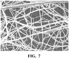
- Continuous nanofibers were made using a lab scale spin unit with a flat disk driven (such as illustrated in Figure 1 ) by a high-speed electrical motor.
- a spinning solution of 8.0 wt% poly (ethylene oxide) with an average molecular weight (Mw) of about 300,000 and 92.0% water by weight was mixed until homogeneous and poured into a syringe pump for delivery to the rotational flat disk with a 3.0 cm diameter through the supply tube with a flow rate of about 2 cc/min.
- the rotation speed was set to a constant 40,000 rpm.
- the solution viscosity was 3,150 cP at 25°C. No electrical field was used during this test.
- Nanofibers were collected on an aluminum foil that was held in tubular shape about 25 cm in diameter surround the spinning disk, and the spinning disk was placed at the center of the tubular collector. There was no shaping fluid applied.
- An SEM image of the nanofibers can be seen in Figure 7 .
- the fiber size was measured from images of the nanofibers collected on aluminum foil using SEM.
- the fiber diameters were measured from 643 counts of nanofibers and determined to be in the range of 20 nm to 500 nm with a median value of 127 nm.
- the average fiber diameter was 141 nm with a standard deviation of 62 nm with a 95% confidence interval.
- Continuous fibers were made using a standard ITW TurboDisk atomizer with a special 20 hole turbine plate, and control enclosure for high voltage and turbine speed control from ITW Automotive Finishing Group.
- the Pulse Track System is used to maintain constant speed of the rotary atomizer during the coating application.
- High voltage is provided from voltage master power supply.
- a spinning solution of 10.0% poly(ethylene oxide) with an Mw of about 300,000 and 92.0% water by weight was mixed until homogeneous, and poured into a 3:1 2.54 cm diaphragm pump for delivery to the rotational disk atomizer through the supply tube with a constant flow rate of 60 cc/min.
- a 15 cm diameter concave-shaped spin disk was used.
- the rotation speed was set to a constant 27,000 rpm.
- a +50 kV power supply was used in current control mode and the current was set to 0.02 am.
- the high voltage ran at about 73 kV during this test.
- the solution viscosity was 12,500 cP at 25°C.
- the disk was serrated with about 937 pitches at the edge of the disk. Fibers were collected on aluminum foil that was held in tubular shape about 284 cm in diameter surrounding the spinning disk, and the spinning disk was placed at the center of the tubular collector. There was no shaping air applied. An SEM image of the fibers can be seen in Figure. 8 .
- the fiber size was measured from images of the fibers collected on aluminum foil using SEM.
- the fiber diameters were measured from 660 counts of fibers and determined to be in the range of 32 nm to 502 nm with a median value of 182 nm.
- the average fiber diameter was 191 nm with a standard deviation of 76 nm, with a 95% confidence interval.
- Reference Example 2 was prepared similarly to Comparative Example A, except a 15 cm flat spin disk with reservoir and disk inner edge (such as illustrated in Figure 6 ) was used. All test conditions were identical as Comparative Example A.
- An SEM image of the nanofibers can be seen in Figure 9 .
- the fiber size was measured from images of the nanofibers collected on aluminum foil using SEM.
- the fiber diameters were measured from 571 counts of nanofibers and determined to be in the range of 23 nm to 190 nm with a median value of 82 nm.
- the average fiber diameter was 84 nm with a standard deviation of 27 nm, with a 95% confidence interval.
- the flat spin disk with reservoir used in Reference Example 2 made smaller fiber diameter fibers than the concave spin disk of Comparative Example A.
- Reference Example 3 was prepared similarly to Reference Example 2, except a 30 cm flat spin disk with reservoir and disk inner edge was used. A spin solution of 12.0% poly (ethylene oxide) with an Mw of about 300,000 and 88.0% water was used. The viscosity of this solution was 34,000 cP at 25°C. In this test, a much higher flow rate was used at 200 cc/min, and the disk rotation speed was 21,000 rpm. There was no shaping air applied. An SEM image of the nanofibers can be seen in Fig. 10 . The fiber size was measured from images of the nanofibers collected on aluminum foil using SEM.
- the fiber diameters were measured from 790 counts of nanofibers and determined to be in the range of 52 nm to 716 nm with a median value of 222 nm.
- the average fiber diameter was 254 nm with a standard deviation of 122 nm, with a 95% confidence interval.
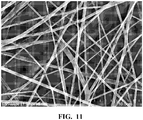
- Reference Example 4 was prepared similarly to Reference Example 3. A 30 cm flat spin disk with reservoir and disk inner edge was used. A spin solution of 15% poly(vinyl alcohol) (DuPont Evanol 80-18) and 85% water by weight was used. The viscosity of this solution is 5,850 cP at 25°C. In this test, the flow rate was set as 33 cc/min, and the disk rotation speed was 8,000 rpm. There was no shaping air applied. An SEM image of the nanofibers can be seen in Fig. 11 . The fiber size was measured from images of the nanofibers collected on aluminum foil using SEM.
- the fiber diameters were measured from 323 counts of nanofibers and determined to be in the range of 98 nm to 665 nm with a median value of 264 nm.
- the average fiber diameter was 277 nm with a standard deviation of 172 nm, with a 95% confidence interval.
Landscapes
- Engineering & Computer Science (AREA)
- Chemical & Material Sciences (AREA)
- Nanotechnology (AREA)
- Textile Engineering (AREA)
- Mechanical Engineering (AREA)
- Composite Materials (AREA)
- Materials Engineering (AREA)
- Crystallography & Structural Chemistry (AREA)
- General Physics & Mathematics (AREA)
- Condensed Matter Physics & Semiconductors (AREA)
- Physics & Mathematics (AREA)
- Nonwoven Fabrics (AREA)
- Spinning Methods And Devices For Manufacturing Artificial Fibers (AREA)
Applications Claiming Priority (2)
| Application Number | Priority Date | Filing Date | Title |
|---|---|---|---|
| US788107P | 2007-12-17 | 2007-12-17 | |
| PCT/US2008/087058 WO2009079523A2 (en) | 2007-12-17 | 2008-12-17 | Centrifugal solution spun nanofiber process |
Publications (2)
| Publication Number | Publication Date |
|---|---|
| EP2222903A2 EP2222903A2 (en) | 2010-09-01 |
| EP2222903B1 true EP2222903B1 (en) | 2018-01-24 |
Family
ID=40720014
Family Applications (1)
| Application Number | Title | Priority Date | Filing Date |
|---|---|---|---|
| EP08862609.8A Active EP2222903B1 (en) | 2007-12-17 | 2008-12-17 | Centrifugal solution spun nanofiber process |
Country Status (7)
| Country | Link |
|---|---|
| US (1) | US9834865B2 (enExample) |
| EP (1) | EP2222903B1 (enExample) |
| JP (1) | JP5501249B2 (enExample) |
| KR (1) | KR101680908B1 (enExample) |
| CN (1) | CN101896650B (enExample) |
| BR (1) | BRPI0819494A2 (enExample) |
| WO (1) | WO2009079523A2 (enExample) |
Families Citing this family (43)
| Publication number | Priority date | Publication date | Assignee | Title |
|---|---|---|---|---|
| US8277711B2 (en) * | 2007-03-29 | 2012-10-02 | E I Du Pont De Nemours And Company | Production of nanofibers by melt spinning |
| US20090326128A1 (en) * | 2007-05-08 | 2009-12-31 | Javier Macossay-Torres | Fibers and methods relating thereto |
| EP2271796A4 (en) | 2008-03-17 | 2012-01-04 | Univ Texas | SUPERFINE FIBER GENERATING SPINNING NOZZLE AND ITS USE |
| CN102282301B (zh) | 2009-01-16 | 2014-07-30 | Zeus工业品公司 | 利用高粘度材料对ptfe进行电纺丝 |
| US20130268062A1 (en) | 2012-04-05 | 2013-10-10 | Zeus Industrial Products, Inc. | Composite prosthetic devices |
| EP2461766A4 (en) | 2009-08-07 | 2013-09-18 | Zeus Ind Products Inc | PROSTHETIC DEVICE COMPRISING AN ELECTROSTATIC-FILTERED FIBROUS LAYER AND METHOD OF MANUFACTURING THE SAME |
| JP2013520584A (ja) | 2010-10-14 | 2013-06-06 | ゼウス インダストリアル プロダクツ インコーポレイテッド | 抗菌基質 |
| RU2581871C2 (ru) | 2011-01-28 | 2016-04-20 | Мерит Медикал Системз, Инк. | Стент, покрытый электроспряденным птфэ, и способ применения |
| US8778240B2 (en) | 2011-02-07 | 2014-07-15 | Fiberio Technology Corporation | Split fiber producing devices and methods for the production of microfibers and nanofibers |
| WO2012109240A2 (en) * | 2011-02-07 | 2012-08-16 | Fiberio Technology Corporation | Split fiber producing devices and methods for the production of microfibers and nanofibers |
| JP6042355B2 (ja) * | 2011-03-09 | 2016-12-14 | ボード・オブ・リージエンツ,ザ・ユニバーシテイ・オブ・テキサス・システム | 繊維の製造のための装置及び方法 |
| JP6118341B2 (ja) | 2011-12-21 | 2017-04-19 | イー・アイ・デュポン・ドウ・ヌムール・アンド・カンパニーE.I.Du Pont De Nemours And Company | 遠心紡糸法によって繊維ウェブを積層する方法 |
| BR112014016892B1 (pt) | 2012-01-16 | 2019-12-17 | Merit Medical Systems Inc | dispositivos médicos cobertos por material fiado por rotação e métodos para construção dos mesmos |
| CZ308269B6 (cs) * | 2012-09-17 | 2020-04-08 | Výzkumný ústav potravinářský Praha, v.v.i. | Zařízení s proměnlivou geometrií pro odstředivou výrobu mikrovláken a nanovláken |
| US10507268B2 (en) | 2012-09-19 | 2019-12-17 | Merit Medical Systems, Inc. | Electrospun material covered medical appliances and methods of manufacture |
| US9198999B2 (en) | 2012-09-21 | 2015-12-01 | Merit Medical Systems, Inc. | Drug-eluting rotational spun coatings and methods of use |
| KR101414739B1 (ko) * | 2012-10-25 | 2014-07-07 | 주식회사 우리나노 | 나노섬유의 제조방법 |
| KR101354509B1 (ko) | 2012-11-06 | 2014-01-23 | 주식회사 우리나노 | 나노섬유 필라멘트의 제조방법 |
| US9577235B2 (en) | 2012-12-18 | 2017-02-21 | Sabic Global Technologies B.V. | High temperature melt integrity battery separators via spinning |
| WO2014110300A1 (en) * | 2013-01-09 | 2014-07-17 | Harvard Apparatus Regenerative Technology | Synthetic scaffolds |
| CN105121728A (zh) * | 2013-02-20 | 2015-12-02 | 纳幕尔杜邦公司 | 纳米纤维网结构 |
| WO2014159399A1 (en) | 2013-03-13 | 2014-10-02 | Merit Medical Systems, Inc. | Methods, systems, and apparatuses for manufacturing rotational spun appliances |
| WO2014159710A1 (en) | 2013-03-13 | 2014-10-02 | Merit Medical Systems, Inc. | Serially deposited fiber materials and associated devices and methods |
| US9988742B2 (en) | 2013-04-12 | 2018-06-05 | Donaldson Company, Inc. | Centrifugal electrospinning process |
| KR101381020B1 (ko) * | 2013-04-22 | 2014-04-04 | 숭실대학교산학협력단 | 원심력을 이용한 나노섬유 제조장치 및 제조방법 |
| WO2015009962A1 (en) * | 2013-07-17 | 2015-01-22 | Sabic Global Technologies B.V. | Force spun sub-micrometer fiber and applications |
| KR101426738B1 (ko) * | 2013-09-11 | 2014-08-06 | 전북대학교산학협력단 | 원심력이 결합된 전기방사를 이용한 나노섬유의 제조방법 |
| US9610588B2 (en) * | 2013-10-21 | 2017-04-04 | E I Du Pont De Nemours And Company | Electret nanofibrous web as air filtration media |
| JP2016534239A (ja) * | 2013-10-22 | 2016-11-04 | イー・アイ・デュポン・ドウ・ヌムール・アンド・カンパニーE.I.Du Pont De Nemours And Company | メルトスピン法によるポリプロピレンファイングレードナノファイバウェブ |
| KR102252127B1 (ko) * | 2013-10-22 | 2021-05-17 | 이 아이 듀폰 디 네모아 앤드 캄파니 | 중합체 나노섬유의 제조 장치 |
| US11203132B2 (en) | 2013-11-20 | 2021-12-21 | Trusscore Inc. | Method and system for forming composites |
| US9365951B2 (en) | 2014-01-30 | 2016-06-14 | Kimberly-Clark Worldwide, Inc. | Negative polarity on the nanofiber line |
| JP6172677B2 (ja) * | 2014-04-25 | 2017-08-02 | 国立大学法人秋田大学 | 繊維の製造装置およびこれを用いた不織布の製造装置 |
| ES2989899T3 (es) | 2015-02-26 | 2024-11-28 | Merit Medical Systems Inc | Aparatos médicos en capas |
| WO2017184615A1 (en) * | 2016-04-18 | 2017-10-26 | Cummins Filtration Ip, Inc. | Nanofiber filter media for high performance applications |
| WO2017214085A1 (en) * | 2016-06-10 | 2017-12-14 | Ascend Performance Materials Operations Llc | Solution-spun polyamide nanofiber nonwovens |
| EP3679181A4 (en) | 2017-09-08 | 2021-05-12 | The Board of Regents of The University of Texas System | Mechanoluminescence polymer doped fabrics and methods |
| CN109457303B (zh) * | 2018-12-05 | 2023-12-08 | 河北耐诺科技有限公司 | 离心力辅助发射极 |
| WO2020172207A1 (en) | 2019-02-20 | 2020-08-27 | Board Of Regents, University Of Texas System | Handheld/portable apparatus for the production of microfibers, submicron fibers and nanofibers |
| CN110656383A (zh) * | 2019-10-24 | 2020-01-07 | 季华实验室 | 一种离心静电纺丝装置 |
| US12194205B2 (en) | 2020-04-30 | 2025-01-14 | Research Triangle Institute | Multi-layer air filtration media with integrated disinfection capability |
| WO2022183215A1 (en) | 2021-02-26 | 2022-09-01 | Merit Medical Systems, Inc. | Fibrous constructs with therapeutic material particles |
| EP4301910A4 (en) | 2021-03-02 | 2024-08-14 | Board of Regents, The University of Texas System | HANDHELD/PORTABLE DEVICE FOR THE PRODUCTION OF FINE FIBERS |
Family Cites Families (14)
| Publication number | Priority date | Publication date | Assignee | Title |
|---|---|---|---|---|
| JPS49110910A (enExample) * | 1973-03-02 | 1974-10-22 | ||
| GB1573116A (en) * | 1977-03-11 | 1980-08-13 | Ici Ltd | Production of formaldehyde resin fibres by centrifugal spining |
| JPS5530467A (en) * | 1978-08-28 | 1980-03-04 | Denki Kagaku Kogyo Kk | Production of alumina fiber precursor and device therefor |
| FI68866C (fi) * | 1979-04-09 | 1985-11-11 | Ici Ltd | Centrifugalspinnkopp och foerfarande foer centrifugalspinnandeav fibrer |
| JPS6010127B2 (ja) * | 1982-09-20 | 1985-03-15 | 株式会社佐藤技術研究所 | 融体から特定サイズの繊維を製造する方法 |
| KR920006865B1 (ko) | 1984-05-18 | 1992-08-21 | 워싱톤 유니버시티 테크놀러지 어소우시에이츠 인코오퍼레이티드 | 입자나 액적을 피복하는 방법과 장치 |
| US4861653A (en) | 1987-09-02 | 1989-08-29 | E. I. Du Pont De Nemours And Company | Pitch carbon fibers and batts |
| US6641773B2 (en) * | 2001-01-10 | 2003-11-04 | The United States Of America As Represented By The Secretary Of The Army | Electro spinning of submicron diameter polymer filaments |
| CN1472373A (zh) | 2003-03-28 | 2004-02-04 | 中国科学院长春应用化学研究所 | 旋碟纺丝法及纺丝装置 |
| US7134857B2 (en) | 2004-04-08 | 2006-11-14 | Research Triangle Institute | Electrospinning of fibers using a rotatable spray head |
| US20060012084A1 (en) * | 2004-07-13 | 2006-01-19 | Armantrout Jack E | Electroblowing web formation process |
| EP1998798B1 (en) * | 2006-03-28 | 2013-02-27 | LNK Chemsolutions, LLC. | Method of manufacturing fibrous hemostatic bandages |
| US8303874B2 (en) | 2006-03-28 | 2012-11-06 | E I Du Pont De Nemours And Company | Solution spun fiber process |
| US8277711B2 (en) * | 2007-03-29 | 2012-10-02 | E I Du Pont De Nemours And Company | Production of nanofibers by melt spinning |
-
2008
- 2008-12-16 US US12/335,816 patent/US9834865B2/en active Active
- 2008-12-17 JP JP2010539714A patent/JP5501249B2/ja active Active
- 2008-12-17 WO PCT/US2008/087058 patent/WO2009079523A2/en not_active Ceased
- 2008-12-17 CN CN2008801208620A patent/CN101896650B/zh active Active
- 2008-12-17 EP EP08862609.8A patent/EP2222903B1/en active Active
- 2008-12-17 BR BRPI0819494-7A patent/BRPI0819494A2/pt not_active IP Right Cessation
- 2008-12-17 KR KR1020107015710A patent/KR101680908B1/ko active Active
Also Published As
| Publication number | Publication date |
|---|---|
| WO2009079523A2 (en) | 2009-06-25 |
| BRPI0819494A2 (pt) | 2015-05-26 |
| EP2222903A2 (en) | 2010-09-01 |
| JP5501249B2 (ja) | 2014-05-21 |
| US9834865B2 (en) | 2017-12-05 |
| WO2009079523A3 (en) | 2009-10-01 |
| KR20100108382A (ko) | 2010-10-06 |
| US20090160099A1 (en) | 2009-06-25 |
| JP2011506797A (ja) | 2011-03-03 |
| CN101896650A (zh) | 2010-11-24 |
| KR101680908B1 (ko) | 2016-11-29 |
| CN101896650B (zh) | 2012-12-12 |
Similar Documents
| Publication | Publication Date | Title |
|---|---|---|
| EP2222903B1 (en) | Centrifugal solution spun nanofiber process | |
| EP1999304B1 (en) | Solution spun fiber process | |
| KR101519169B1 (ko) | 용융 방사에 의한 나노섬유의 제조 | |
| CN103998667B (zh) | 平铺来自离心式纺丝工艺的纤维网的方法 | |
| CN102471934A (zh) | 聚酰胺纳米纤维的静电纺丝 | |
| JP2011501790A (ja) | 電気機械的紡績による繊維形成 | |
| CN1367276A (zh) | 精细纤维状高分子织物的制造方法 | |
| JP5473144B2 (ja) | ナノファイバー製造方法 | |
| TWI541398B (zh) | 聚醯胺奈米纖維及藉由電紡技術製備聚醯胺奈米纖維之方法 | |
| Krupa et al. | Electrosprayed nanoparticles for nanofiber coating |
Legal Events
| Date | Code | Title | Description |
|---|---|---|---|
| PUAI | Public reference made under article 153(3) epc to a published international application that has entered the european phase |
Free format text: ORIGINAL CODE: 0009012 |
|
| 17P | Request for examination filed |
Effective date: 20100520 |
|
| AK | Designated contracting states |
Kind code of ref document: A2 Designated state(s): AT BE BG CH CY CZ DE DK EE ES FI FR GB GR HR HU IE IS IT LI LT LU LV MC MT NL NO PL PT RO SE SI SK TR |
|
| AX | Request for extension of the european patent |
Extension state: AL BA MK RS |
|
| DAX | Request for extension of the european patent (deleted) | ||
| 17Q | First examination report despatched |
Effective date: 20160922 |
|
| STAA | Information on the status of an ep patent application or granted ep patent |
Free format text: STATUS: EXAMINATION IS IN PROGRESS |
|
| GRAP | Despatch of communication of intention to grant a patent |
Free format text: ORIGINAL CODE: EPIDOSNIGR1 |
|
| STAA | Information on the status of an ep patent application or granted ep patent |
Free format text: STATUS: GRANT OF PATENT IS INTENDED |
|
| INTG | Intention to grant announced |
Effective date: 20170809 |
|
| GRAS | Grant fee paid |
Free format text: ORIGINAL CODE: EPIDOSNIGR3 |
|
| GRAA | (expected) grant |
Free format text: ORIGINAL CODE: 0009210 |
|
| STAA | Information on the status of an ep patent application or granted ep patent |
Free format text: STATUS: THE PATENT HAS BEEN GRANTED |
|
| AK | Designated contracting states |
Kind code of ref document: B1 Designated state(s): AT BE BG CH CY CZ DE DK EE ES FI FR GB GR HR HU IE IS IT LI LT LU LV MC MT NL NO PL PT RO SE SI SK TR |
|
| REG | Reference to a national code |
Ref country code: GB Ref legal event code: FG4D |
|
| REG | Reference to a national code |
Ref country code: CH Ref legal event code: EP |
|
| REG | Reference to a national code |
Ref country code: AT Ref legal event code: REF Ref document number: 965849 Country of ref document: AT Kind code of ref document: T Effective date: 20180215 |
|
| REG | Reference to a national code |
Ref country code: IE Ref legal event code: FG4D |
|
| REG | Reference to a national code |
Ref country code: DE Ref legal event code: R096 Ref document number: 602008053892 Country of ref document: DE |
|
| REG | Reference to a national code |
Ref country code: NL Ref legal event code: MP Effective date: 20180124 |
|
| REG | Reference to a national code |
Ref country code: LT Ref legal event code: MG4D |
|
| REG | Reference to a national code |
Ref country code: AT Ref legal event code: MK05 Ref document number: 965849 Country of ref document: AT Kind code of ref document: T Effective date: 20180124 |
|
| PG25 | Lapsed in a contracting state [announced via postgrant information from national office to epo] |
Ref country code: NL Free format text: LAPSE BECAUSE OF FAILURE TO SUBMIT A TRANSLATION OF THE DESCRIPTION OR TO PAY THE FEE WITHIN THE PRESCRIBED TIME-LIMIT Effective date: 20180124 |
|
| PG25 | Lapsed in a contracting state [announced via postgrant information from national office to epo] |
Ref country code: ES Free format text: LAPSE BECAUSE OF FAILURE TO SUBMIT A TRANSLATION OF THE DESCRIPTION OR TO PAY THE FEE WITHIN THE PRESCRIBED TIME-LIMIT Effective date: 20180124 Ref country code: HR Free format text: LAPSE BECAUSE OF FAILURE TO SUBMIT A TRANSLATION OF THE DESCRIPTION OR TO PAY THE FEE WITHIN THE PRESCRIBED TIME-LIMIT Effective date: 20180124 Ref country code: NO Free format text: LAPSE BECAUSE OF FAILURE TO SUBMIT A TRANSLATION OF THE DESCRIPTION OR TO PAY THE FEE WITHIN THE PRESCRIBED TIME-LIMIT Effective date: 20180424 Ref country code: CY Free format text: LAPSE BECAUSE OF FAILURE TO SUBMIT A TRANSLATION OF THE DESCRIPTION OR TO PAY THE FEE WITHIN THE PRESCRIBED TIME-LIMIT Effective date: 20180124 Ref country code: LT Free format text: LAPSE BECAUSE OF FAILURE TO SUBMIT A TRANSLATION OF THE DESCRIPTION OR TO PAY THE FEE WITHIN THE PRESCRIBED TIME-LIMIT Effective date: 20180124 Ref country code: FI Free format text: LAPSE BECAUSE OF FAILURE TO SUBMIT A TRANSLATION OF THE DESCRIPTION OR TO PAY THE FEE WITHIN THE PRESCRIBED TIME-LIMIT Effective date: 20180124 |
|
| PG25 | Lapsed in a contracting state [announced via postgrant information from national office to epo] |
Ref country code: IS Free format text: LAPSE BECAUSE OF FAILURE TO SUBMIT A TRANSLATION OF THE DESCRIPTION OR TO PAY THE FEE WITHIN THE PRESCRIBED TIME-LIMIT Effective date: 20180524 Ref country code: LV Free format text: LAPSE BECAUSE OF FAILURE TO SUBMIT A TRANSLATION OF THE DESCRIPTION OR TO PAY THE FEE WITHIN THE PRESCRIBED TIME-LIMIT Effective date: 20180124 Ref country code: GR Free format text: LAPSE BECAUSE OF FAILURE TO SUBMIT A TRANSLATION OF THE DESCRIPTION OR TO PAY THE FEE WITHIN THE PRESCRIBED TIME-LIMIT Effective date: 20180425 Ref country code: PL Free format text: LAPSE BECAUSE OF FAILURE TO SUBMIT A TRANSLATION OF THE DESCRIPTION OR TO PAY THE FEE WITHIN THE PRESCRIBED TIME-LIMIT Effective date: 20180124 Ref country code: SE Free format text: LAPSE BECAUSE OF FAILURE TO SUBMIT A TRANSLATION OF THE DESCRIPTION OR TO PAY THE FEE WITHIN THE PRESCRIBED TIME-LIMIT Effective date: 20180124 Ref country code: BG Free format text: LAPSE BECAUSE OF FAILURE TO SUBMIT A TRANSLATION OF THE DESCRIPTION OR TO PAY THE FEE WITHIN THE PRESCRIBED TIME-LIMIT Effective date: 20180424 Ref country code: AT Free format text: LAPSE BECAUSE OF FAILURE TO SUBMIT A TRANSLATION OF THE DESCRIPTION OR TO PAY THE FEE WITHIN THE PRESCRIBED TIME-LIMIT Effective date: 20180124 |
|
| REG | Reference to a national code |
Ref country code: DE Ref legal event code: R097 Ref document number: 602008053892 Country of ref document: DE |
|
| PG25 | Lapsed in a contracting state [announced via postgrant information from national office to epo] |
Ref country code: IT Free format text: LAPSE BECAUSE OF FAILURE TO SUBMIT A TRANSLATION OF THE DESCRIPTION OR TO PAY THE FEE WITHIN THE PRESCRIBED TIME-LIMIT Effective date: 20180124 Ref country code: EE Free format text: LAPSE BECAUSE OF FAILURE TO SUBMIT A TRANSLATION OF THE DESCRIPTION OR TO PAY THE FEE WITHIN THE PRESCRIBED TIME-LIMIT Effective date: 20180124 Ref country code: RO Free format text: LAPSE BECAUSE OF FAILURE TO SUBMIT A TRANSLATION OF THE DESCRIPTION OR TO PAY THE FEE WITHIN THE PRESCRIBED TIME-LIMIT Effective date: 20180124 |
|
| PG25 | Lapsed in a contracting state [announced via postgrant information from national office to epo] |
Ref country code: DK Free format text: LAPSE BECAUSE OF FAILURE TO SUBMIT A TRANSLATION OF THE DESCRIPTION OR TO PAY THE FEE WITHIN THE PRESCRIBED TIME-LIMIT Effective date: 20180124 Ref country code: CZ Free format text: LAPSE BECAUSE OF FAILURE TO SUBMIT A TRANSLATION OF THE DESCRIPTION OR TO PAY THE FEE WITHIN THE PRESCRIBED TIME-LIMIT Effective date: 20180124 Ref country code: SK Free format text: LAPSE BECAUSE OF FAILURE TO SUBMIT A TRANSLATION OF THE DESCRIPTION OR TO PAY THE FEE WITHIN THE PRESCRIBED TIME-LIMIT Effective date: 20180124 |
|
| PLBE | No opposition filed within time limit |
Free format text: ORIGINAL CODE: 0009261 |
|
| STAA | Information on the status of an ep patent application or granted ep patent |
Free format text: STATUS: NO OPPOSITION FILED WITHIN TIME LIMIT |
|
| 26N | No opposition filed |
Effective date: 20181025 |
|
| PG25 | Lapsed in a contracting state [announced via postgrant information from national office to epo] |
Ref country code: SI Free format text: LAPSE BECAUSE OF FAILURE TO SUBMIT A TRANSLATION OF THE DESCRIPTION OR TO PAY THE FEE WITHIN THE PRESCRIBED TIME-LIMIT Effective date: 20180124 |
|
| REG | Reference to a national code |
Ref country code: CH Ref legal event code: PL |
|
| PG25 | Lapsed in a contracting state [announced via postgrant information from national office to epo] |
Ref country code: MC Free format text: LAPSE BECAUSE OF FAILURE TO SUBMIT A TRANSLATION OF THE DESCRIPTION OR TO PAY THE FEE WITHIN THE PRESCRIBED TIME-LIMIT Effective date: 20180124 Ref country code: LU Free format text: LAPSE BECAUSE OF NON-PAYMENT OF DUE FEES Effective date: 20181217 |
|
| REG | Reference to a national code |
Ref country code: IE Ref legal event code: MM4A |
|
| REG | Reference to a national code |
Ref country code: BE Ref legal event code: MM Effective date: 20181231 |
|
| PG25 | Lapsed in a contracting state [announced via postgrant information from national office to epo] |
Ref country code: IE Free format text: LAPSE BECAUSE OF NON-PAYMENT OF DUE FEES Effective date: 20181217 |
|
| PG25 | Lapsed in a contracting state [announced via postgrant information from national office to epo] |
Ref country code: BE Free format text: LAPSE BECAUSE OF NON-PAYMENT OF DUE FEES Effective date: 20181231 |
|
| PG25 | Lapsed in a contracting state [announced via postgrant information from national office to epo] |
Ref country code: CH Free format text: LAPSE BECAUSE OF NON-PAYMENT OF DUE FEES Effective date: 20181231 Ref country code: LI Free format text: LAPSE BECAUSE OF NON-PAYMENT OF DUE FEES Effective date: 20181231 |
|
| PG25 | Lapsed in a contracting state [announced via postgrant information from national office to epo] |
Ref country code: MT Free format text: LAPSE BECAUSE OF NON-PAYMENT OF DUE FEES Effective date: 20181217 |
|
| PG25 | Lapsed in a contracting state [announced via postgrant information from national office to epo] |
Ref country code: TR Free format text: LAPSE BECAUSE OF FAILURE TO SUBMIT A TRANSLATION OF THE DESCRIPTION OR TO PAY THE FEE WITHIN THE PRESCRIBED TIME-LIMIT Effective date: 20180124 |
|
| PG25 | Lapsed in a contracting state [announced via postgrant information from national office to epo] |
Ref country code: PT Free format text: LAPSE BECAUSE OF FAILURE TO SUBMIT A TRANSLATION OF THE DESCRIPTION OR TO PAY THE FEE WITHIN THE PRESCRIBED TIME-LIMIT Effective date: 20180124 |
|
| PG25 | Lapsed in a contracting state [announced via postgrant information from national office to epo] |
Ref country code: HU Free format text: LAPSE BECAUSE OF FAILURE TO SUBMIT A TRANSLATION OF THE DESCRIPTION OR TO PAY THE FEE WITHIN THE PRESCRIBED TIME-LIMIT; INVALID AB INITIO Effective date: 20081217 |
|
| REG | Reference to a national code |
Ref country code: DE Ref legal event code: R081 Ref document number: 602008053892 Country of ref document: DE Owner name: DUPONT SAFETY & CONSTRUCTION, INC., WILMINGTON, US Free format text: FORMER OWNER: E.I. DU PONT DE NEMOURS AND COMPANY, WILMINGTON, DEL., US |
|
| REG | Reference to a national code |
Ref country code: GB Ref legal event code: 732E Free format text: REGISTERED BETWEEN 20221027 AND 20221102 |
|
| P01 | Opt-out of the competence of the unified patent court (upc) registered |
Effective date: 20230528 |
|
| PGFP | Annual fee paid to national office [announced via postgrant information from national office to epo] |
Ref country code: DE Payment date: 20241029 Year of fee payment: 17 |
|
| PGFP | Annual fee paid to national office [announced via postgrant information from national office to epo] |
Ref country code: GB Payment date: 20241031 Year of fee payment: 17 |
|
| PGFP | Annual fee paid to national office [announced via postgrant information from national office to epo] |
Ref country code: FR Payment date: 20241111 Year of fee payment: 17 |