EP2221452A2 - Spiralverdichter - Google Patents
Spiralverdichter Download PDFInfo
- Publication number
- EP2221452A2 EP2221452A2 EP10001676A EP10001676A EP2221452A2 EP 2221452 A2 EP2221452 A2 EP 2221452A2 EP 10001676 A EP10001676 A EP 10001676A EP 10001676 A EP10001676 A EP 10001676A EP 2221452 A2 EP2221452 A2 EP 2221452A2
- Authority
- EP
- European Patent Office
- Prior art keywords
- scroll
- mirror plate
- movable scroll
- oldham
- ring
- Prior art date
- Legal status (The legal status is an assumption and is not a legal conclusion. Google has not performed a legal analysis and makes no representation as to the accuracy of the status listed.)
- Granted
Links
Images


Classifications
-
- F—MECHANICAL ENGINEERING; LIGHTING; HEATING; WEAPONS; BLASTING
- F04—POSITIVE - DISPLACEMENT MACHINES FOR LIQUIDS; PUMPS FOR LIQUIDS OR ELASTIC FLUIDS
- F04C—ROTARY-PISTON, OR OSCILLATING-PISTON, POSITIVE-DISPLACEMENT MACHINES FOR LIQUIDS; ROTARY-PISTON, OR OSCILLATING-PISTON, POSITIVE-DISPLACEMENT PUMPS
- F04C18/00—Rotary-piston pumps specially adapted for elastic fluids
- F04C18/02—Rotary-piston pumps specially adapted for elastic fluids of arcuate-engagement type, i.e. with circular translatory movement of co-operating members, each member having the same number of teeth or tooth-equivalents
-
- F—MECHANICAL ENGINEERING; LIGHTING; HEATING; WEAPONS; BLASTING
- F01—MACHINES OR ENGINES IN GENERAL; ENGINE PLANTS IN GENERAL; STEAM ENGINES
- F01C—ROTARY-PISTON OR OSCILLATING-PISTON MACHINES OR ENGINES
- F01C17/00—Arrangements for drive of co-operating members, e.g. for rotary piston and casing
- F01C17/06—Arrangements for drive of co-operating members, e.g. for rotary piston and casing using cranks, universal joints or similar elements
- F01C17/066—Arrangements for drive of co-operating members, e.g. for rotary piston and casing using cranks, universal joints or similar elements with an intermediate piece sliding along perpendicular axes, e.g. Oldham coupling
-
- F—MECHANICAL ENGINEERING; LIGHTING; HEATING; WEAPONS; BLASTING
- F04—POSITIVE - DISPLACEMENT MACHINES FOR LIQUIDS; PUMPS FOR LIQUIDS OR ELASTIC FLUIDS
- F04C—ROTARY-PISTON, OR OSCILLATING-PISTON, POSITIVE-DISPLACEMENT MACHINES FOR LIQUIDS; ROTARY-PISTON, OR OSCILLATING-PISTON, POSITIVE-DISPLACEMENT PUMPS
- F04C18/00—Rotary-piston pumps specially adapted for elastic fluids
- F04C18/02—Rotary-piston pumps specially adapted for elastic fluids of arcuate-engagement type, i.e. with circular translatory movement of co-operating members, each member having the same number of teeth or tooth-equivalents
- F04C18/0207—Rotary-piston pumps specially adapted for elastic fluids of arcuate-engagement type, i.e. with circular translatory movement of co-operating members, each member having the same number of teeth or tooth-equivalents both members having co-operating elements in spiral form
- F04C18/0246—Details concerning the involute wraps or their base, e.g. geometry
- F04C18/0253—Details concerning the base
-
- F—MECHANICAL ENGINEERING; LIGHTING; HEATING; WEAPONS; BLASTING
- F04—POSITIVE - DISPLACEMENT MACHINES FOR LIQUIDS; PUMPS FOR LIQUIDS OR ELASTIC FLUIDS
- F04C—ROTARY-PISTON, OR OSCILLATING-PISTON, POSITIVE-DISPLACEMENT MACHINES FOR LIQUIDS; ROTARY-PISTON, OR OSCILLATING-PISTON, POSITIVE-DISPLACEMENT PUMPS
- F04C29/00—Component parts, details or accessories of pumps or pumping installations, not provided for in groups F04C18/00 - F04C28/00
-
- F—MECHANICAL ENGINEERING; LIGHTING; HEATING; WEAPONS; BLASTING
- F04—POSITIVE - DISPLACEMENT MACHINES FOR LIQUIDS; PUMPS FOR LIQUIDS OR ELASTIC FLUIDS
- F04C—ROTARY-PISTON, OR OSCILLATING-PISTON, POSITIVE-DISPLACEMENT MACHINES FOR LIQUIDS; ROTARY-PISTON, OR OSCILLATING-PISTON, POSITIVE-DISPLACEMENT PUMPS
- F04C23/00—Combinations of two or more pumps, each being of rotary-piston or oscillating-piston type, specially adapted for elastic fluids; Pumping installations specially adapted for elastic fluids; Multi-stage pumps specially adapted for elastic fluids
- F04C23/008—Hermetic pumps
Definitions
- the present invention relates to a scroll type compressor for performing compression through the engagement between a fixed scroll and a movable scroll.
- a scroll type compressor that includes a fixed scroll and a movable scroll engaged with the fixed scroll, the fixed scroll and the movable scroll being accommodated in a hermetically sealed container, and compresses gas by rotating the movable scroll.
- the movable scroll is supported through an Oldham's ring by a housing (which is also called as a compliant frame.
- the Oldham's ring is a member for constraining the movable scroll so that the movable scroll makes a whirling motion, and a fitting pawl for fixing (fixing key) is fitted in a groove provided in the housing, whereby the Oldham's ring is fixed to the housing.
- a recently known scroll type compressor is configured so that the Oldham's ring is not fixed to the housing, but fixed to the fixed scroll in order to enhance the assembling precision concerning the positioning (phase) of the fixed scroll and the movable scroll.
- the fixing locking pawl extending from the Oldham's ring extends beyond the movable scroll and is fitted to the fixed scroll (see JP-A-2006-161818 and JP-A-2000-283067 , for example).
- the fixing locking pawl of the Oldham's ring is longer, and thus the fixing locking pawl is easily broken.
- the movable scroll is located between the Oldham's ring and the fixed scroll, and thus the movable scroll is provided with an escape portion which avoids the fixing locking pawl extending from the Oldham's ring.
- this escape portion obstructs this chuck fixing work.
- the movable scroll 125 is constructed by providing a lap 125B is provided to a circular mirror plate 125A.
- a pair of guide grooves for receiving and guiding a projecting portion provided to the Oldham's ring are formed in the mirror plate 125A so as to be displaced in phase by 180°, and right and left circumferential portions of the mirror plate 125A are cut out in parallel to the guide direction of the guide grooves 190, thereby forming escape portions 191.
- the present invention has been implemented in view of the foregoing situation, and has an object to provide a scroll type compressor that is excellent in strength of Oldham's ring and processing performance.
- a scroll type compressor (1) including a fixed scroll (23) having a mirror plate (23A) and a lap (23B) provided to the mirror plate, a movable scroll (25) having a mirror plate (25A, 125A) and a lap (25B, 125B) that is provided to the mirror plate (25A, 125A) andengagedwiththefixedscroll, and an Oldham's ring (61) that is disposed on the back side of the movable scroll and constrains rotation of the movable scroll on the axis thereof
- the Oldham's ring has a pair of fixing locking pawls (85) extending from the back side of the movable scroll and fitted to the fixed scroll, each of the fixing locking pawls is provided with a reinforcing portion (85A) at the base portion thereof, and the mirror plate of the movable scroll is cut out in a concave shape at the edge portion thereof in conform
- the reinforcing portion is provided to the base portion of the fixing locking pawl of the Oldham's ring, and thus the strength of the fixing locking pawl is enhanced, so that the fixing locking pawl is hardly broken.
- the edge portion of the movable scroll is cut out in a concaved shape to form the escape portion for the fixing locking pawl. Therefore, the cut-out amount of the edge portion can be made smaller as compared with the prior art. Accordingly, the edge portion of the movable scroll can be left to the extent that a generally available three-point chuck can besecuredtothemovablescroll. Therefore, theprocessingusing the three-point chuck can be performed.
- both the side surfaces (91A)of the concaved cut-out constituting the escape portion may be shaped so as to be fitted to the reinforcing portion. According to the above scroll type compressor, the width of the escape portion can be suppressed to the minimum level required for the movement of the reinforcing portion. Therefore, the cut-out amount of the edge portion of the mirror plate of the movable scroll can be made further smaller.
- the reinforcing portion is larger in width than the fixing locking pawl in a predetermined direction. According to the above scroll type compressor, the fixing locking pawl of the Oldham's ring can be further strengthened.
- the reinforcing portion is provided to the base portion of the fixing locking pawl of the Oldham's ring, and thus the strength of the fixing locking pawl is enhanced, so that the fixing locking pawl is hardly broken. Furthermore, the edge portion of the movable scroll is cut out in a concaved shape to form the escape portion for the fixing locking pawl. Therefore, the cut-out amount of the edge portion can be made smaller as compared with the prior art. Accordingly, the edge portion of the movable scroll can be left to the extent that a generally available three-point chuck can be secured to the movable scroll. Therefore, the three-point chuck can be easily secured to the movable scroll.
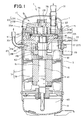
- reference numeral 1 represents a scroll type compressor having a high internal pressure.
- the compressor 1 is connected to a refrigerant circuit (not shown) in which refrigerant is circulated to perform a refrigeration cycle operation, and compresses the refrigerant.
- the compressor 1 has a hermetically-sealed dome type casing 3 which is designed in an elongated cylindrical shape.
- the casing 3 is constructed as a pressure container by a casing main body 5 as a cylindrical body portion having an axis line in the up-and-down direction, a saucer-shaped upper cap 7 which is air-tightly welded and integrally joined to the upper end portion of the casing main body 5 and has an upwardly projecting convex surface, and a saucer-shaped lower cap 7 having a downwardly projecting convex surface, and the inside of the casing 3 is designed to have a cavity.
- a scroll compression mechanism 11 for compressing refrigerant, and a driving motor 13 disposed below the scroll compression mechanism 11 are mounted in the casing 3.
- the scroll compression mechanism 11 and he driving motor 13 are connected to each other through a driving shaft 15 which is disposed so as to extend in the up-and-down direction in the casing 3.
- a gap space 17 is formed between the scroll compression mechanism 11 and the driving motor 13.
- the scroll compression mechanism 11 has a housing 21 as a substantially cylindrical accommodating member which is opened at the upper side thereof and has a bottom, a fixed scroll 23 which is disposed in close contact with the upper surface of the housing 21, and a movable scroll 25 which is disposed between the fixed scroll 23 and the housing 21 and engaged with the fixed scroll 23.
- the housing 21 is press-fitted in the casing main body 5 over the whole outer peripheral surface thereof in the peripheral direction.
- the inside of the casing 3 is compartmented into a high pressure space 27 at the lower side of the housing 21 and a discharge space 29 at the upper side of the housing 21, and the respective spaces 27 and 29 intercommunicate with each other through a longitudinal groove (passage ) 71 which is formed on the outer peripheries of the housing 21 and the fixed scroll 23 so as to extend longitudinally.
- the housing 21 is provided with a housing space 21A in which an eccentric axial portion 15A of the driving shaft 15 is rotated, and a radial bearing portion 21B extending downwardly from the center of the lower surface of the housing 21. Furthermore, the housing 21 is provided with a radial bearing hole 28 penetrating between the lower end surface of the radial bearing portion 21B and the bottom surface of the housing space 21A, and the upper end portion of the driving shaft 15 is rotatably fitted and mounted through the radial bearing 30 in the radial bearing hole 28.
- a suction pipe 31 for leading the refrigerant in the refrigerant circuit to the scroll compression mechanism 11 penetrates through the upper cap 7 of the casing 3 and is air-tightly fixed to the upper cap 7, and a discharge pipe 33 for discharging the refrigerant in the casing 3 to the outside of the casing 3 penetrates through the casing main body 5 and is air-tightly fixed to the casing main body 5.
- the suction pipe 31 extends in the up-and-down direction in the discharge space 29, and the inner end portion of the suction pipe 31 penetrates through a suction port 32 opened to the fixed scroll 23 of the scroll compression mechanism 11, and intercommunicates with the compression chamber 35. Accordingly, the refrigerant is sucked into the compression chamber 35 through the suction pipe 31.
- the driving motor 13 has an annular stator 37 fixed to the inner wall surface of the casing 3, and a rotor 39 which is freely rotatably provided inside the stator 37, the motor 13 is constructed by a DC motor, and the movable scroll 25 of the scroll compression mechanism 11 is connected to the rotor 39 through the driving shaft 15.
- the lower space 40 at the lower side of the driving motor 13 is kept to a high-pressure state, and oil is stocked at the inner bottom portion of the lower cap 9 corresponding to the lower end portion of the lower space 40.
- An oil supply path 41 as a part of a high-pressure oil supply unit is formed in the driving shaft 15, the oil supply path 41 intercommunicates with an oil chamber 43 at the back side of the movable scroll 25.
- a pickup 45 is connected to the lower end of the driving shaft 15, and the pickup 45 scoops up the oil stocked at the inner bottom portion of the lower cap 9.
- the scooped oil is passed through the oil supply path 41 of the driving shaft 15 and supplied to the oil chamber 43 at the back side of the movable scroll 25, and supplied from the oil chamber 43 to each sliding portion and the compression chamber 35 of the scroll compression mechanism 11 through an intercommunication path 51 provided to the movable scroll 25.
- the fixed scroll 23 comprises a mirror plate 23A and a scroll-like (involute type) lap 23b formed on the lower surface of the mirror plate 23A.
- the movable scroll 25 comprises a mirror plate 25A and a scroll-type (involute type) lap 25B formed on the upper surface of the mirror plate 25A.
- the lap 23B of the fixed scroll 23 and the lap 25B of the movable scroll 25 are engaged with each other, whereby plural compression chambers 35 are formed by both the laps 23B and 25B between the fixed scroll 23 and the movable scroll 25.
- the movable scroll 25 is supported through the Oldham's ring 61 by the fixed scroll 23, and a cylindrical boss portion 25C having a bottom is projected from the center portion of the lower surface of the mirror plate 25A. Furthermore, an eccentric shaft portion 15A is provided to the upper end of the driving shaft 15, and the eccentric shaft portion 15A is rotatably fitted in the boss portion 25C of the movable scroll 25.
- a counter weight portion 63 is provided to the driving shaft 15 at the lower side of the radial bearing portion 21B of the housing 21 in order to establish dynamic balance with the movable scroll 25, the eccentric shaft portion 15A, etc..
- the driving shaft 15 rotates while keeping the weight balance by the counter weight portion 63, whereby the movable scroll 25 does not rotate on its axis, but swirls.
- the compression chamber 35 is configured so that in connection with the swirling of the movable scroll 25, the refrigerant sucked by the suction pipe 31 is compressed due to contraction of the volume between both the laps 23B and 25B.
- a discharge hole 73 is provided at the center portion of the fixed scroll 23, and gas refrigerant discharged from the discharge hole 73 is passed through the discharge valve 75 and discharged to the discharge space 29, and flows out into the high-pressure space 27 at the lower side of the housing 21 through a longitudinal groove 71 formed on the respective outer peripheries of the housing 21 and the fixed scroll 23.
- This high-pressure refrigerant is discharged to the outside of the casing 3 through the discharge pipe 33 provided to the casing main body 5.
- a guide member (gas flow deflecting member) 77 is provided to the lower side of the longitudinal groove 71.
- the guide member 77 deflects the flow direction of the gas refrigerant (which is discharged from the discharge valve 75 to the discharge space 29, passed through the longitudinal groove 71 and flows downwardly) toward a shielding plate 79 and/or in the horizontal direction along the inner surface of the casing main body 5 (casing 3), and also guides the gas refrigerant through a passage between the shielding plate 79 at the upper side of the coil end 81 of the driving motor 13 and the inner surface of the casing main body 5 (casing 3) and then to the discharge pipe 33.
- the driving motor 13 When the driving motor 13 is driven, the rotor 39 rotates relative to the stator 37, and thus the driving shaft 15 rotates.
- the driving shaft 15 rotates, the movable scroll 25 of the scroll compression mechanism 11 does not rotate on its axis, but makes only the swirling motion relative to the fixed scroll 23. Accordingly, low-pressure refrigerant is passed through the suction pipe 31, and sucked from the peripheral edge side of the compression chamber 35 into the compression chamber 35, so that this refrigerant is compressed in connection with volume variation of the compression chamber 35.
- the compressed refrigerant is increased in pressure, passed from the compression chamber 35 to the discharge valve 75, and discharged to the discharge space 29.
- the refrigerant is passed through the longitudinal groove 71 formed on the respective outer peripheries of the housing 21 and the fixed scroll 23, and then flows out to the high-pressure space at the lower side of the housing 21. Still further, this high-pressure refrigerant is discharged through the discharge pipe 33 provided to the casing main body 5 to the outside of the casing 3. After the refrigerant discharged to the outside of the casing 3 is circulated in the refrigerant circuit (not shown), the refrigerant is sucked through the suction pipe 31 into the compressor 1 again, and compressed in the compressor. The circulation of the refrigerant as described above is repeated.
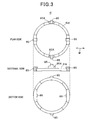
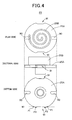
- Fig. 2 is an exploded diagram of the movable scroll 25 and the fixed scroll 23 of the scroll compression mechanism 11, and Fig. 3 is plan, side and bottom views of the Oldham's ring 61. Fig. 4 is plan, side and bottom views of the movable scroll 25.
- reference numeral 16 represents a seal ring.
- the movable scroll 25 is supported through the Oldham's ring 61 in the housing 21.
- the Oldham's ring 61 is a member for constraining the rotation of the movable scroll 25 on its axis and swirling the movable scroll 25.
- the Oldham's ring 61 is fitted in the ring groove 20 formed on the upper surface of the housing 61, and the back surface of the movable scroll 25 is disposed in close contact with the upper surface 61A of the Oldham's ring 61.
- a pair of fixing locking pawls 85 which are provided to be displaced in phase by 180° and a pair of projecting portions 86 which are provided to be displaced in phase by 180° are provided on the upper surface 61A of the Oldham's ring 61.
- the fixing locking pawls 85 projects so as to extend from the upper surface 61A beyond the movable scroll 25 and reach the fixed scroll 23, and it is fitted to the fixed scroll 23. As described above, the fixing locking pawl 85 is fitted to the fixed scroll 23, whereby the Oldham's ring 61 is fixed in the casing 3.
- the projecting portion 86 is a member for constraining the rotation of the movable scroll which is rotated between the Oldham' ring 61 and the fixed scroll 23, but swirling the movable scroll 25.
- the movable scroll 25 has a substantially circular mirror plate 25A, and a lap 25B provided to the upper surface of the mirror plate 25A.
- a pair of guide grooves 90 to which the projecting portions 86 of the Oldham's ring 61 are fitted are formed at the bottom surface side of the mirror plate 25A, and the escape portions 91 for avoiding the fixing locking pawls 85 are formed on the circumference of the mirror plate 25A.
- the projections 86 of the Oldham' s ring are fitted in the guide grooves 90, whereby the movable scroll 25 is constrained from rotating on its axis when it is rotationally driven.
- the movable scroll 25 relatively moves between the Oldham's ring 61 and the fixed scroll 23. Therefore, a load is imposed on the Oldham's ring 61 which regulates the movement of the movable scroll 25, and particularly an extremely large load is imposed on the fixing locking pawls 85 for fixing the Oldham's ring 61. Furthermore, according to this embodiment, the Oldham' s ring 61 is formed by aluminum die-casting, and thus the strength of the fixing locking pawl 85 is a critical problem.
- a reinforcing portion 85A is formed at the base of the fixing locking pawl 85 to reinforce the strength of the fixing locking pawl 85.
- the reinforcing portion 85A is designed in a pedestal-like shape to be thicker than the fixing locking pawl 85, and the strength of the fixing lockingpawl 85 is reinforced by providing the reinforcing portion 85A as described above.
- the reinforcing portion 85A is designed to be larger in width than the fixing locking pawl 85 in the guide direction M of the projecting portions 86, whereby the fixing locking pawl 85 has high strength with respect to an impact when the movable scroll 25 is driven.
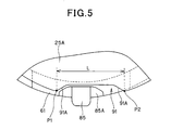
- the escape portion 91 is formed at the edge portion of the mirror plate 25A of the movable scroll 25 in conformity with a moving range of each reinforcing portion 85A, that is, so as to avoid the movement range of each reinforcing portion 85A. As shown in Fig. 4 , each of the escape portions 91 is not formed by simply cutting out the circumference of the edge portion of the mirror plate 25A along a line N1 extending along the movement direction of the reinforcing portion 85A, but formed by a concaved notch.
- the circumference of the mirror plate 25A is extended by the amount corresponding to the total length of the circular arcs between the points P1 and P2. Accordingly, the three-point chuck can be secured to the movable scroll 25 at three gripping positions which avoid the escape portions 91 and the guide grooves 90 and also are displaced in phase by 120°.
- both the side surfaces 91A of the concave notch constituting the escape portion 91 are designed to bematched with the shape of the reinforcing portion 85A and also fitted to the reinforcing portion 85A. Accordingly, the lateral width L of the escape portion 91 is suppressed to the minimum level required for the movement of the reinforcing portion 85A which is designed to sufficiently reinforce the strength of the fixing locking pawl 85. Therefore, the cut-out amount of the circumference (edge portion) of the mirror plate 25A can be suppressed to the minimum level. Accordingly, both the reinforcement of the strength of the fixing locking pawl 85 and also the securement of the gripping positions of the three-point chuck can be performed.
- Both the end portions of the reinforcing portion 85A is shaped to have a predetermined curvature, and thus the escape portions 91 can be simply formed by slice processing.
- the reinforcing portion 85A is provided to the base of the fixing locking pawl 85 of the Oldham's ring 61, and thus the strength is enhanced, so that the fixing locking pawl 85 is hardly broken.
- the escape portions 91 are formed by cutting out the circumference of the mirror plate 25 in a concave shape, and thus the cut-out amount of the circumference of the mirror plate 25A can be reduced as compared with the prior art. Accordingly, a generally available three-point chuck can be secured to grip positions which avoid the escape portions 91 and the guide grooves 90, and under this state, the lap 25B, etc. can be excellently processed.
- both the side surfaces 91A of each escape portion 91 are designed to be fitted to the reinforcing portion 85A, and thus the width L of the escape portion 91 can be suppressed to the minimum level required for the movement of the reinforcing portion 85A, and thus the cut-out amount of the edge portion of the mirror plate of the movable scroll can be made smaller.
- both the reinforcement of the strength of the fixing locking pawl 85 and the securement of the gripping positions of the three-point chuck can be performed.
Landscapes
- Engineering & Computer Science (AREA)
- Mechanical Engineering (AREA)
- General Engineering & Computer Science (AREA)
- Rotary Pumps (AREA)
- Applications Or Details Of Rotary Compressors (AREA)
Applications Claiming Priority (1)
| Application Number | Priority Date | Filing Date | Title |
|---|---|---|---|
| JP2009037382A JP5253224B2 (ja) | 2009-02-20 | 2009-02-20 | スクロール型圧縮機 |
Publications (3)
| Publication Number | Publication Date |
|---|---|
| EP2221452A2 true EP2221452A2 (de) | 2010-08-25 |
| EP2221452A3 EP2221452A3 (de) | 2014-04-30 |
| EP2221452B1 EP2221452B1 (de) | 2017-07-05 |
Family
ID=42045453
Family Applications (1)
| Application Number | Title | Priority Date | Filing Date |
|---|---|---|---|
| EP10001676.5A Active EP2221452B1 (de) | 2009-02-20 | 2010-02-18 | Spiralverdichter |
Country Status (5)
| Country | Link |
|---|---|
| US (1) | US8303280B2 (de) |
| EP (1) | EP2221452B1 (de) |
| JP (1) | JP5253224B2 (de) |
| KR (1) | KR101164320B1 (de) |
| CN (1) | CN101865131A (de) |
Families Citing this family (11)
| Publication number | Priority date | Publication date | Assignee | Title |
|---|---|---|---|---|
| TWI435196B (zh) | 2009-10-15 | 2014-04-21 | 派伏塔系統公司 | 氣體流量控制方法及裝置 |
| FR3000143B1 (fr) * | 2012-12-21 | 2018-11-09 | Danfoss Commercial Compressors | Compresseur a spirales ayant des premier et second joints de oldham |
| WO2014206334A1 (en) | 2013-06-27 | 2014-12-31 | Emerson Climate Technologies, Inc. | Scroll compressor with oil management system |
| KR101971819B1 (ko) | 2015-04-30 | 2019-04-23 | 에머슨 클라이미트 테크놀로지스 (쑤저우) 코., 엘티디. | 스크롤 압축기 |
| US10400770B2 (en) | 2016-02-17 | 2019-09-03 | Emerson Climate Technologies, Inc. | Compressor with Oldham assembly |
| US11136977B2 (en) | 2018-12-31 | 2021-10-05 | Emerson Climate Technologies, Inc. | Compressor having Oldham keys |
| KR102266715B1 (ko) * | 2019-10-22 | 2021-06-21 | 엘지전자 주식회사 | 스크롤 압축기 |
| WO2021124973A1 (ja) * | 2019-12-20 | 2021-06-24 | パナソニックIpマネジメント株式会社 | スクロール圧縮機 |
| JP2021116731A (ja) * | 2020-01-24 | 2021-08-10 | パナソニックIpマネジメント株式会社 | スクロール圧縮機 |
| KR102550370B1 (ko) * | 2021-09-17 | 2023-07-04 | 엘지전자 주식회사 | 스크롤 압축기 |
| KR20230091699A (ko) | 2021-12-16 | 2023-06-23 | 삼성전자주식회사 | 스크롤 압축기 및 이를 포함하는 가전기기 |
Citations (2)
| Publication number | Priority date | Publication date | Assignee | Title |
|---|---|---|---|---|
| JP2000283067A (ja) | 1999-03-31 | 2000-10-10 | Mitsubishi Electric Corp | スクロール圧縮機 |
| JP2006161818A (ja) | 2006-02-07 | 2006-06-22 | Mitsubishi Electric Corp | スクロール圧縮機 |
Family Cites Families (13)
| Publication number | Priority date | Publication date | Assignee | Title |
|---|---|---|---|---|
| US5580230A (en) * | 1986-08-22 | 1996-12-03 | Copeland Corporation | Scroll machine having an axially compliant mounting for a scroll member |
| US5407335A (en) * | 1986-08-22 | 1995-04-18 | Copeland Corporation | Non-orbiting scroll mounting arrangements for a scroll machine |
| US4795323A (en) * | 1987-11-02 | 1989-01-03 | Carrier Corporation | Scroll machine with anti-rotation mechanism |
| DE69103604T2 (de) * | 1990-10-01 | 1994-12-22 | Copeland Corp | Oldham's Kupplung für Spiralverdichter. |
| JP3601073B2 (ja) * | 1994-05-06 | 2004-12-15 | ダイキン工業株式会社 | スクロール形流体機械 |
| JPH0932755A (ja) * | 1995-07-13 | 1997-02-04 | Mitsubishi Heavy Ind Ltd | スクロール型流体機械 |
| JPH09158861A (ja) * | 1995-12-05 | 1997-06-17 | Hitachi Ltd | スクロール圧縮機 |
| JP3918277B2 (ja) * | 1998-02-20 | 2007-05-23 | 株式会社日立製作所 | スクロール圧縮機 |
| JP2003035282A (ja) * | 2001-07-19 | 2003-02-07 | Mitsubishi Heavy Ind Ltd | スクロール型流体機械 |
| JP2003065257A (ja) * | 2001-08-30 | 2003-03-05 | Sanyo Electric Co Ltd | スクロール圧縮機 |
| JP2004100660A (ja) * | 2002-09-13 | 2004-04-02 | Hitachi Home & Life Solutions Inc | スクロール圧縮機 |
| KR100686760B1 (ko) * | 2003-09-18 | 2007-02-23 | 엘지전자 주식회사 | 자전 방지구조를 갖는 스크롤 압축기 |
| JP2007205423A (ja) | 2006-01-31 | 2007-08-16 | Toshiba Kyaria Kk | オルダムリングおよびこれを備えた流体機械 |
-
2009
- 2009-02-20 JP JP2009037382A patent/JP5253224B2/ja active Active
- 2009-12-14 KR KR1020090124061A patent/KR101164320B1/ko not_active Expired - Fee Related
-
2010
- 2010-02-12 CN CN201010118420A patent/CN101865131A/zh active Pending
- 2010-02-18 EP EP10001676.5A patent/EP2221452B1/de active Active
- 2010-02-19 US US12/709,089 patent/US8303280B2/en not_active Expired - Fee Related
Patent Citations (2)
| Publication number | Priority date | Publication date | Assignee | Title |
|---|---|---|---|---|
| JP2000283067A (ja) | 1999-03-31 | 2000-10-10 | Mitsubishi Electric Corp | スクロール圧縮機 |
| JP2006161818A (ja) | 2006-02-07 | 2006-06-22 | Mitsubishi Electric Corp | スクロール圧縮機 |
Also Published As
| Publication number | Publication date |
|---|---|
| EP2221452B1 (de) | 2017-07-05 |
| JP2010190164A (ja) | 2010-09-02 |
| KR20100095362A (ko) | 2010-08-30 |
| JP5253224B2 (ja) | 2013-07-31 |
| US20100215536A1 (en) | 2010-08-26 |
| US8303280B2 (en) | 2012-11-06 |
| EP2221452A3 (de) | 2014-04-30 |
| CN101865131A (zh) | 2010-10-20 |
| KR101164320B1 (ko) | 2012-07-09 |
Similar Documents
| Publication | Publication Date | Title |
|---|---|---|
| EP2221452B1 (de) | Spiralverdichter | |
| EP2221481B1 (de) | Spiralverdichter | |
| CN105164419B (zh) | 涡旋式压缩机 | |
| CN109477482B (zh) | 涡旋式压缩机 | |
| KR101099923B1 (ko) | 스크롤형 압축기 | |
| EP2581605A2 (de) | Spiralverdichter mit Bypassloch | |
| JP2013076390A (ja) | スクロール圧縮機 | |
| WO2013046694A1 (ja) | スクロール圧縮機 | |
| EP2628956A2 (de) | Scroll-Fluidmaschine | |
| EP2194274B1 (de) | Spiralverdichter | |
| EP2221480B1 (de) | Spiralverdichter | |
| EP3567212A1 (de) | Verdichter mit oldham-ring | |
| JP6763225B2 (ja) | スクロール圧縮機 | |
| CN114729630B (zh) | 压缩机 | |
| US20210079916A1 (en) | Scroll compressor | |
| CN108368847B (zh) | 涡旋压缩机 | |
| CN111566350B (zh) | 涡旋式压缩机 | |
| CN212155146U (zh) | 涡旋式压缩机 | |
| EP3647596B1 (de) | Rotationsverdichter | |
| JP3243014U (ja) | 電動圧縮機 | |
| US8939741B2 (en) | Scroll compressor | |
| JP2003227478A (ja) | スクロール型圧縮機 | |
| JP2006077732A (ja) | スクロール圧縮機 | |
| JP2006348933A (ja) | 回転式圧縮機 |
Legal Events
| Date | Code | Title | Description |
|---|---|---|---|
| PUAI | Public reference made under article 153(3) epc to a published international application that has entered the european phase |
Free format text: ORIGINAL CODE: 0009012 |
|
| 17P | Request for examination filed |
Effective date: 20100218 |
|
| AK | Designated contracting states |
Kind code of ref document: A2 Designated state(s): AT BE BG CH CY CZ DE DK EE ES FI FR GB GR HR HU IE IS IT LI LT LU LV MC MK MT NL NO PL PT RO SE SI SK SM TR |
|
| AX | Request for extension of the european patent |
Extension state: AL BA RS |
|
| PUAL | Search report despatched |
Free format text: ORIGINAL CODE: 0009013 |
|
| AK | Designated contracting states |
Kind code of ref document: A3 Designated state(s): AT BE BG CH CY CZ DE DK EE ES FI FR GB GR HR HU IE IS IT LI LT LU LV MC MK MT NL NO PL PT RO SE SI SK SM TR |
|
| AX | Request for extension of the european patent |
Extension state: AL BA RS |
|
| RIC1 | Information provided on ipc code assigned before grant |
Ipc: F04C 18/02 20060101ALI20140321BHEP Ipc: F01C 17/06 20060101AFI20140321BHEP |
|
| RBV | Designated contracting states (corrected) |
Designated state(s): AT BE BG CH CY CZ DE DK EE ES FI FR GB GR HR HU IE IS IT LI LT LU LV MC MK MT NL NO PL PT RO SE SI SK SM TR |
|
| 17Q | First examination report despatched |
Effective date: 20160218 |
|
| GRAP | Despatch of communication of intention to grant a patent |
Free format text: ORIGINAL CODE: EPIDOSNIGR1 |
|
| STAA | Information on the status of an ep patent application or granted ep patent |
Free format text: STATUS: GRANT OF PATENT IS INTENDED |
|
| INTG | Intention to grant announced |
Effective date: 20170223 |
|
| GRAS | Grant fee paid |
Free format text: ORIGINAL CODE: EPIDOSNIGR3 |
|
| GRAA | (expected) grant |
Free format text: ORIGINAL CODE: 0009210 |
|
| STAA | Information on the status of an ep patent application or granted ep patent |
Free format text: STATUS: THE PATENT HAS BEEN GRANTED |
|
| AK | Designated contracting states |
Kind code of ref document: B1 Designated state(s): AT BE BG CH CY CZ DE DK EE ES FI FR GB GR HR HU IE IS IT LI LT LU LV MC MK MT NL NO PL PT RO SE SI SK SM TR |
|
| REG | Reference to a national code |
Ref country code: GB Ref legal event code: FG4D |
|
| REG | Reference to a national code |
Ref country code: CH Ref legal event code: EP |
|
| REG | Reference to a national code |
Ref country code: AT Ref legal event code: REF Ref document number: 906751 Country of ref document: AT Kind code of ref document: T Effective date: 20170715 |
|
| REG | Reference to a national code |
Ref country code: IE Ref legal event code: FG4D |
|
| REG | Reference to a national code |
Ref country code: DE Ref legal event code: R096 Ref document number: 602010043383 Country of ref document: DE |
|
| REG | Reference to a national code |
Ref country code: NL Ref legal event code: MP Effective date: 20170705 |
|
| REG | Reference to a national code |
Ref country code: AT Ref legal event code: MK05 Ref document number: 906751 Country of ref document: AT Kind code of ref document: T Effective date: 20170705 |
|
| REG | Reference to a national code |
Ref country code: LT Ref legal event code: MG4D |
|
| PG25 | Lapsed in a contracting state [announced via postgrant information from national office to epo] |
Ref country code: LT Free format text: LAPSE BECAUSE OF FAILURE TO SUBMIT A TRANSLATION OF THE DESCRIPTION OR TO PAY THE FEE WITHIN THE PRESCRIBED TIME-LIMIT Effective date: 20170705 Ref country code: FI Free format text: LAPSE BECAUSE OF FAILURE TO SUBMIT A TRANSLATION OF THE DESCRIPTION OR TO PAY THE FEE WITHIN THE PRESCRIBED TIME-LIMIT Effective date: 20170705 Ref country code: HR Free format text: LAPSE BECAUSE OF FAILURE TO SUBMIT A TRANSLATION OF THE DESCRIPTION OR TO PAY THE FEE WITHIN THE PRESCRIBED TIME-LIMIT Effective date: 20170705 Ref country code: NO Free format text: LAPSE BECAUSE OF FAILURE TO SUBMIT A TRANSLATION OF THE DESCRIPTION OR TO PAY THE FEE WITHIN THE PRESCRIBED TIME-LIMIT Effective date: 20171005 Ref country code: SE Free format text: LAPSE BECAUSE OF FAILURE TO SUBMIT A TRANSLATION OF THE DESCRIPTION OR TO PAY THE FEE WITHIN THE PRESCRIBED TIME-LIMIT Effective date: 20170705 Ref country code: AT Free format text: LAPSE BECAUSE OF FAILURE TO SUBMIT A TRANSLATION OF THE DESCRIPTION OR TO PAY THE FEE WITHIN THE PRESCRIBED TIME-LIMIT Effective date: 20170705 Ref country code: NL Free format text: LAPSE BECAUSE OF FAILURE TO SUBMIT A TRANSLATION OF THE DESCRIPTION OR TO PAY THE FEE WITHIN THE PRESCRIBED TIME-LIMIT Effective date: 20170705 |
|
| PG25 | Lapsed in a contracting state [announced via postgrant information from national office to epo] |
Ref country code: ES Free format text: LAPSE BECAUSE OF FAILURE TO SUBMIT A TRANSLATION OF THE DESCRIPTION OR TO PAY THE FEE WITHIN THE PRESCRIBED TIME-LIMIT Effective date: 20170705 Ref country code: GR Free format text: LAPSE BECAUSE OF FAILURE TO SUBMIT A TRANSLATION OF THE DESCRIPTION OR TO PAY THE FEE WITHIN THE PRESCRIBED TIME-LIMIT Effective date: 20171006 Ref country code: IS Free format text: LAPSE BECAUSE OF FAILURE TO SUBMIT A TRANSLATION OF THE DESCRIPTION OR TO PAY THE FEE WITHIN THE PRESCRIBED TIME-LIMIT Effective date: 20171105 Ref country code: PL Free format text: LAPSE BECAUSE OF FAILURE TO SUBMIT A TRANSLATION OF THE DESCRIPTION OR TO PAY THE FEE WITHIN THE PRESCRIBED TIME-LIMIT Effective date: 20170705 Ref country code: BG Free format text: LAPSE BECAUSE OF FAILURE TO SUBMIT A TRANSLATION OF THE DESCRIPTION OR TO PAY THE FEE WITHIN THE PRESCRIBED TIME-LIMIT Effective date: 20171005 Ref country code: LV Free format text: LAPSE BECAUSE OF FAILURE TO SUBMIT A TRANSLATION OF THE DESCRIPTION OR TO PAY THE FEE WITHIN THE PRESCRIBED TIME-LIMIT Effective date: 20170705 |
|
| REG | Reference to a national code |
Ref country code: DE Ref legal event code: R097 Ref document number: 602010043383 Country of ref document: DE |
|
| PG25 | Lapsed in a contracting state [announced via postgrant information from national office to epo] |
Ref country code: DK Free format text: LAPSE BECAUSE OF FAILURE TO SUBMIT A TRANSLATION OF THE DESCRIPTION OR TO PAY THE FEE WITHIN THE PRESCRIBED TIME-LIMIT Effective date: 20170705 Ref country code: RO Free format text: LAPSE BECAUSE OF FAILURE TO SUBMIT A TRANSLATION OF THE DESCRIPTION OR TO PAY THE FEE WITHIN THE PRESCRIBED TIME-LIMIT Effective date: 20170705 Ref country code: CZ Free format text: LAPSE BECAUSE OF FAILURE TO SUBMIT A TRANSLATION OF THE DESCRIPTION OR TO PAY THE FEE WITHIN THE PRESCRIBED TIME-LIMIT Effective date: 20170705 |
|
| PLBE | No opposition filed within time limit |
Free format text: ORIGINAL CODE: 0009261 |
|
| STAA | Information on the status of an ep patent application or granted ep patent |
Free format text: STATUS: NO OPPOSITION FILED WITHIN TIME LIMIT |
|
| PG25 | Lapsed in a contracting state [announced via postgrant information from national office to epo] |
Ref country code: SM Free format text: LAPSE BECAUSE OF FAILURE TO SUBMIT A TRANSLATION OF THE DESCRIPTION OR TO PAY THE FEE WITHIN THE PRESCRIBED TIME-LIMIT Effective date: 20170705 Ref country code: EE Free format text: LAPSE BECAUSE OF FAILURE TO SUBMIT A TRANSLATION OF THE DESCRIPTION OR TO PAY THE FEE WITHIN THE PRESCRIBED TIME-LIMIT Effective date: 20170705 Ref country code: SK Free format text: LAPSE BECAUSE OF FAILURE TO SUBMIT A TRANSLATION OF THE DESCRIPTION OR TO PAY THE FEE WITHIN THE PRESCRIBED TIME-LIMIT Effective date: 20170705 Ref country code: IT Free format text: LAPSE BECAUSE OF FAILURE TO SUBMIT A TRANSLATION OF THE DESCRIPTION OR TO PAY THE FEE WITHIN THE PRESCRIBED TIME-LIMIT Effective date: 20170705 |
|
| 26N | No opposition filed |
Effective date: 20180406 |
|
| PG25 | Lapsed in a contracting state [announced via postgrant information from national office to epo] |
Ref country code: SI Free format text: LAPSE BECAUSE OF FAILURE TO SUBMIT A TRANSLATION OF THE DESCRIPTION OR TO PAY THE FEE WITHIN THE PRESCRIBED TIME-LIMIT Effective date: 20170705 |
|
| REG | Reference to a national code |
Ref country code: CH Ref legal event code: PL |
|
| PG25 | Lapsed in a contracting state [announced via postgrant information from national office to epo] |
Ref country code: MC Free format text: LAPSE BECAUSE OF FAILURE TO SUBMIT A TRANSLATION OF THE DESCRIPTION OR TO PAY THE FEE WITHIN THE PRESCRIBED TIME-LIMIT Effective date: 20170705 |
|
| GBPC | Gb: european patent ceased through non-payment of renewal fee |
Effective date: 20180218 |
|
| REG | Reference to a national code |
Ref country code: IE Ref legal event code: MM4A |
|
| REG | Reference to a national code |
Ref country code: BE Ref legal event code: MM Effective date: 20180228 |
|
| PG25 | Lapsed in a contracting state [announced via postgrant information from national office to epo] |
Ref country code: LI Free format text: LAPSE BECAUSE OF NON-PAYMENT OF DUE FEES Effective date: 20180228 Ref country code: CH Free format text: LAPSE BECAUSE OF NON-PAYMENT OF DUE FEES Effective date: 20180228 Ref country code: LU Free format text: LAPSE BECAUSE OF NON-PAYMENT OF DUE FEES Effective date: 20180218 |
|
| REG | Reference to a national code |
Ref country code: FR Ref legal event code: ST Effective date: 20181031 |
|
| PG25 | Lapsed in a contracting state [announced via postgrant information from national office to epo] |
Ref country code: IE Free format text: LAPSE BECAUSE OF NON-PAYMENT OF DUE FEES Effective date: 20180218 |
|
| PG25 | Lapsed in a contracting state [announced via postgrant information from national office to epo] |
Ref country code: BE Free format text: LAPSE BECAUSE OF NON-PAYMENT OF DUE FEES Effective date: 20180228 Ref country code: GB Free format text: LAPSE BECAUSE OF NON-PAYMENT OF DUE FEES Effective date: 20180218 Ref country code: FR Free format text: LAPSE BECAUSE OF NON-PAYMENT OF DUE FEES Effective date: 20180228 |
|
| PG25 | Lapsed in a contracting state [announced via postgrant information from national office to epo] |
Ref country code: MT Free format text: LAPSE BECAUSE OF NON-PAYMENT OF DUE FEES Effective date: 20180218 |
|
| PG25 | Lapsed in a contracting state [announced via postgrant information from national office to epo] |
Ref country code: TR Free format text: LAPSE BECAUSE OF FAILURE TO SUBMIT A TRANSLATION OF THE DESCRIPTION OR TO PAY THE FEE WITHIN THE PRESCRIBED TIME-LIMIT Effective date: 20170705 |
|
| PG25 | Lapsed in a contracting state [announced via postgrant information from national office to epo] |
Ref country code: HU Free format text: LAPSE BECAUSE OF FAILURE TO SUBMIT A TRANSLATION OF THE DESCRIPTION OR TO PAY THE FEE WITHIN THE PRESCRIBED TIME-LIMIT; INVALID AB INITIO Effective date: 20100218 Ref country code: PT Free format text: LAPSE BECAUSE OF FAILURE TO SUBMIT A TRANSLATION OF THE DESCRIPTION OR TO PAY THE FEE WITHIN THE PRESCRIBED TIME-LIMIT Effective date: 20170705 |
|
| PG25 | Lapsed in a contracting state [announced via postgrant information from national office to epo] |
Ref country code: CY Free format text: LAPSE BECAUSE OF FAILURE TO SUBMIT A TRANSLATION OF THE DESCRIPTION OR TO PAY THE FEE WITHIN THE PRESCRIBED TIME-LIMIT Effective date: 20170705 Ref country code: MK Free format text: LAPSE BECAUSE OF NON-PAYMENT OF DUE FEES Effective date: 20170705 |
|
| PGFP | Annual fee paid to national office [announced via postgrant information from national office to epo] |
Ref country code: DE Payment date: 20260218 Year of fee payment: 17 |