EP2221434A1 - Waschanlage für Baustellen- und Aufbereitungsmaterial, gefolgt von einem Recycling des Brauchwassers für einen solchen Waschvorgang - Google Patents
Waschanlage für Baustellen- und Aufbereitungsmaterial, gefolgt von einem Recycling des Brauchwassers für einen solchen Waschvorgang Download PDFInfo
- Publication number
- EP2221434A1 EP2221434A1 EP10290088A EP10290088A EP2221434A1 EP 2221434 A1 EP2221434 A1 EP 2221434A1 EP 10290088 A EP10290088 A EP 10290088A EP 10290088 A EP10290088 A EP 10290088A EP 2221434 A1 EP2221434 A1 EP 2221434A1
- Authority
- EP
- European Patent Office
- Prior art keywords
- water
- tank
- washing
- settling tank
- installation according
- Prior art date
- Legal status (The legal status is an assumption and is not a legal conclusion. Google has not performed a legal analysis and makes no representation as to the accuracy of the status listed.)
- Granted
Links
- XLYOFNOQVPJJNP-UHFFFAOYSA-N water Substances O XLYOFNOQVPJJNP-UHFFFAOYSA-N 0.000 title claims abstract description 129
- 238000005406 washing Methods 0.000 title claims abstract description 65
- 238000004064 recycling Methods 0.000 title claims description 6
- 238000009434 installation Methods 0.000 claims abstract description 49
- 238000004140 cleaning Methods 0.000 claims description 10
- 230000014759 maintenance of location Effects 0.000 claims description 7
- 238000002347 injection Methods 0.000 claims description 6
- 239000007924 injection Substances 0.000 claims description 6
- 238000005086 pumping Methods 0.000 claims description 6
- 238000007689 inspection Methods 0.000 claims description 5
- 238000011084 recovery Methods 0.000 claims description 5
- 238000005520 cutting process Methods 0.000 claims description 4
- 239000003921 oil Substances 0.000 claims description 4
- 238000000926 separation method Methods 0.000 claims description 4
- 238000003860 storage Methods 0.000 claims description 4
- 230000015556 catabolic process Effects 0.000 claims description 3
- 238000006731 degradation reaction Methods 0.000 claims description 3
- 238000012545 processing Methods 0.000 claims description 3
- 238000011144 upstream manufacturing Methods 0.000 claims description 3
- 238000009987 spinning Methods 0.000 claims description 2
- CURLTUGMZLYLDI-UHFFFAOYSA-N Carbon dioxide Chemical compound O=C=O CURLTUGMZLYLDI-UHFFFAOYSA-N 0.000 abstract 4
- 229910002092 carbon dioxide Inorganic materials 0.000 abstract 2
- 239000001569 carbon dioxide Substances 0.000 abstract 2
- 239000013505 freshwater Substances 0.000 abstract 2
- 238000010276 construction Methods 0.000 description 26
- 238000012958 reprocessing Methods 0.000 description 8
- 239000000463 material Substances 0.000 description 5
- 230000033228 biological regulation Effects 0.000 description 4
- 238000010908 decantation Methods 0.000 description 4
- 230000006866 deterioration Effects 0.000 description 3
- 239000007788 liquid Substances 0.000 description 3
- 239000002184 metal Substances 0.000 description 3
- 238000004062 sedimentation Methods 0.000 description 3
- 206010040560 shock Diseases 0.000 description 3
- 230000035939 shock Effects 0.000 description 3
- 239000002699 waste material Substances 0.000 description 3
- 239000010419 fine particle Substances 0.000 description 2
- 238000009415 formwork Methods 0.000 description 2
- 239000002245 particle Substances 0.000 description 2
- 238000003892 spreading Methods 0.000 description 2
- 239000000725 suspension Substances 0.000 description 2
- 239000002351 wastewater Substances 0.000 description 2
- 239000003643 water by type Substances 0.000 description 2
- 206010039740 Screaming Diseases 0.000 description 1
- 239000002253 acid Substances 0.000 description 1
- 230000001934 delay Effects 0.000 description 1
- 238000001035 drying Methods 0.000 description 1
- 238000003912 environmental pollution Methods 0.000 description 1
- 230000005484 gravity Effects 0.000 description 1
- 239000003673 groundwater Substances 0.000 description 1
- 238000010438 heat treatment Methods 0.000 description 1
- 238000000034 method Methods 0.000 description 1
- 238000002156 mixing Methods 0.000 description 1
- 238000006386 neutralization reaction Methods 0.000 description 1
- 239000002689 soil Substances 0.000 description 1
- 239000007921 spray Substances 0.000 description 1
- 239000002352 surface water Substances 0.000 description 1
- 230000009182 swimming Effects 0.000 description 1
Images


Classifications
-
- E—FIXED CONSTRUCTIONS
- E04—BUILDING
- E04G—SCAFFOLDING; FORMS; SHUTTERING; BUILDING IMPLEMENTS OR AIDS, OR THEIR USE; HANDLING BUILDING MATERIALS ON THE SITE; REPAIRING, BREAKING-UP OR OTHER WORK ON EXISTING BUILDINGS
- E04G21/00—Preparing, conveying, or working-up building materials or building elements in situ; Other devices or measures for constructional work
- E04G21/02—Conveying or working-up concrete or similar masses able to be heaped or cast
- E04G21/025—Buckets specially adapted for use with concrete
-
- B—PERFORMING OPERATIONS; TRANSPORTING
- B08—CLEANING
- B08B—CLEANING IN GENERAL; PREVENTION OF FOULING IN GENERAL
- B08B17/00—Methods preventing fouling
- B08B17/02—Preventing deposition of fouling or of dust
- B08B17/06—Preventing deposition of fouling or of dust by giving articles subject to fouling a special shape or arrangement
- B08B17/065—Preventing deposition of fouling or of dust by giving articles subject to fouling a special shape or arrangement the surface having a microscopic surface pattern to achieve the same effect as a lotus flower
-
- B—PERFORMING OPERATIONS; TRANSPORTING
- B08—CLEANING
- B08B—CLEANING IN GENERAL; PREVENTION OF FOULING IN GENERAL
- B08B3/00—Cleaning by methods involving the use or presence of liquid or steam
- B08B3/04—Cleaning involving contact with liquid
- B08B3/10—Cleaning involving contact with liquid with additional treatment of the liquid or of the object being cleaned, e.g. by heat, by electricity or by vibration
- B08B3/14—Removing waste, e.g. labels, from cleaning liquid; Regenerating cleaning liquids
-
- B—PERFORMING OPERATIONS; TRANSPORTING
- B08—CLEANING
- B08B—CLEANING IN GENERAL; PREVENTION OF FOULING IN GENERAL
- B08B9/00—Cleaning hollow articles by methods or apparatus specially adapted thereto
- B08B9/08—Cleaning containers, e.g. tanks
- B08B9/0821—Handling or manipulating containers, e.g. moving or rotating containers in cleaning devices, conveying to or from cleaning devices
- B08B9/0826—Handling or manipulating containers, e.g. moving or rotating containers in cleaning devices, conveying to or from cleaning devices the containers being brought to the cleaning device
-
- B—PERFORMING OPERATIONS; TRANSPORTING
- B08—CLEANING
- B08B—CLEANING IN GENERAL; PREVENTION OF FOULING IN GENERAL
- B08B9/00—Cleaning hollow articles by methods or apparatus specially adapted thereto
- B08B9/08—Cleaning containers, e.g. tanks
- B08B9/093—Cleaning containers, e.g. tanks by the force of jets or sprays
-
- C—CHEMISTRY; METALLURGY
- C02—TREATMENT OF WATER, WASTE WATER, SEWAGE, OR SLUDGE
- C02F—TREATMENT OF WATER, WASTE WATER, SEWAGE, OR SLUDGE
- C02F1/00—Treatment of water, waste water, or sewage
- C02F1/66—Treatment of water, waste water, or sewage by neutralisation; pH adjustment
-
- B—PERFORMING OPERATIONS; TRANSPORTING
- B01—PHYSICAL OR CHEMICAL PROCESSES OR APPARATUS IN GENERAL
- B01D—SEPARATION
- B01D21/00—Separation of suspended solid particles from liquids by sedimentation
- B01D21/02—Settling tanks with single outlets for the separated liquid
-
- C—CHEMISTRY; METALLURGY
- C02—TREATMENT OF WATER, WASTE WATER, SEWAGE, OR SLUDGE
- C02F—TREATMENT OF WATER, WASTE WATER, SEWAGE, OR SLUDGE
- C02F1/00—Treatment of water, waste water, or sewage
- C02F2001/007—Processes including a sedimentation step
-
- C—CHEMISTRY; METALLURGY
- C02—TREATMENT OF WATER, WASTE WATER, SEWAGE, OR SLUDGE
- C02F—TREATMENT OF WATER, WASTE WATER, SEWAGE, OR SLUDGE
- C02F2103/00—Nature of the water, waste water, sewage or sludge to be treated
- C02F2103/001—Runoff or storm water
Definitions
- the present invention relates to a combined installation (a) washing the skips and troughs of trucks spinning top and (b) treatment, followed by recycling, wash water such equipment.
- the short drying time of the concrete residues would not allow to transport the washing equipment from the sites to a unit equipped for the reprocessing of washing water.
- bins are generally associated with a gangway equipped with one and usually two access ladders for the companion in charge of washing, as many gates as there are ladders, and a guardrail arranged on everything the rest of the periphery of the bridge and whose role is to protect the companion against the risk of falling.
- the bridge On site, the bridge is positioned along any side of the tray and, most often, it is attached to it to ensure a perfect stability.
- the truck As for the washing of a truck top, the truck is of course then oriented so that the top overhangs the tank, it is performed by the companion perched on the bridge or using a pressure washing gun fed in water by a pump which takes the water on the surface of the tank, that is to say the least polluted water possible, the washing thus being done in closed circuit, either by means of a pipe of truck specific spray, which projects clean water from a tank also associated with the truck, the water thus fed by the truck flowing after washing in the tank and causing the water level to rise in the bin.
- the Spin trucks are never equipped with a device for recovering polluted water, let alone a device for treating such water.
- the applicant company of the present patent application has designed a washing facility of construction equipment (skips and trucks spindle) constituting a significant advance compared to simple bins.
- This installation described in European Patent No. 1,464,775 published on October 6, 2004 , consists of a gateway of the kind mentioned above, said gateway having the particularity of overhanging a metal structure which is arranged in front of it and which forms in its center a free volume arranged to receive and maintain the bucket to be cleaned, and whatever the type of skip concerned.
- the bucket rests in an inclined position in this cradle-shaped structure such that its upper opening through which the concrete is introduced is turned towards the bridge, a provision which obviously facilitates the washing of the bucket by the companion.
- the cradle-shaped structure itself overhangs a holding tank and settling of washing water to prevent them, stained, do not spread on the floor of the site.
- the applicant company of the present patent application has subsequently perfected such an installation by adding a first unit for treating and recycling the washing water filling its retention and settling tank, this as well to improve the quality of the washing of the construction equipment that to avoid too frequent emptying operations of the tank and routing of dirty water to a concrete plant whose mission will be to reprocess such dirty water.
- the invention thus improved comprises a technical cabinet equipped with a power supply box, a washing pump equipped with a pressurized washing gun, a lifting pump, for pumping dirty water into the water. retention and settling tank, connected to a suction pipe, and a washing water treatment unit arranged between the lifting pump and the washing gun.
- the present invention proposes to overcome all these drawbacks and, to this end, it relates to an installation of the last aforementioned type which is remarkable in that it further comprises a second settling tank disposed under the bridge and a tray of clean water reprocessed arranged under the second settling tank, the technical cabinet is also placed under the bridge, next to the second settling tank and the clean water tank.
- the set composed of the second settling tank, the clean water tank and the technical cabinet which is very compact, is perfectly protected against the risk of shocks since it is arranged under the bridge and overflows the base of the latter neither on the lateral sides, nor on the back side, opposite to that which receives the structure in the form of cradle.
- the second settling tank, the clean water tank and the technical cabinet also overflow the gangway forward and fit partly under the structure arranged to receive and maintain the bucket to be cleaned.
- This construction variant thus makes it possible to exploit all the existing free volume under the bridge and under the cradle-shaped structure, while maintaining the same compactness character to the whole "second settling tank + tank of clean water + technical cabinet "and keeping the same guarantee of protection against shocks.
- the free volume available under the cradle-shaped structure it is obvious that it becomes possible to provide for the use of a second settling tank and a tank of clean water of possible capacity. more important.
- the height of the technical cabinet is substantially equal to the height of the tank of clean water increased by the height of the second settling tank.
- the plant according to the invention is also remarkable in that its treatment unit allows a treatment of the pH before each transfer of water from the second settling tank into the clean water tank in order to reduce the pH value of the water in the allowable range from 6.5 to 8.5.
- the treatment unit comprises means for injecting CO 2 gas into the washing water contained in the second settling tank to treat the pH.
- the installation comprises a bottle of CO 2 gas and an expansion valve fixed on said bottle and connected by a flexible pipe to a CO 2 diffuser disposed in the bottom of the second settling tank, of preferably in the center of this tray.
- the installation also comprises a bottle holder adapted to receive and fix the CO 2 gas bottle at the rear of the second settling tank and the clean water tank.
- the improved treatment by CO 2 gas injection is performed semi-automatically, for example by adjusting the expander at a flow rate of about 50 liters per minute for cycles of each about 3 minutes.
- the first settling tank of the installation according to the invention is provided with a removable decking allowing the companion to access all parts washing the bucket while securing the washing area.
- the first settling tank of the installation according to the invention is extended towards the front of a chute adapted to receive and support a possible concrete flow pipe disposed under the body of the bucket being cleaned, this chute being substantially inclined to allow the flow and recovery of wash water from the inside of the bucket in the holding tank, while keeping the pipe dry during the storage phases of the bucket on the installation to limit its degradation.
- the second settling tank is equipped with: a separation plate arranged vertically, making it possible to separating the possible oils from the water to be treated, a device of the manual valve type, electro-valve for example, for transferring water from said second settling tank into the clean water tank, a device of the manual valve type , electro-valve, cap for example, for the emptying of the second settling tank, and possibly a hatch, for cleaning said second settling tank, which inspection hatch is located on one of the accessible free faces of the last.
- a separation plate arranged vertically, making it possible to separating the possible oils from the water to be treated
- a device of the manual valve type electro-valve for example, for transferring water from said second settling tank into the clean water tank
- a device of the manual valve type electro-valve, cap for example, for the emptying of the second settling tank, and possibly a hatch, for cleaning said second settling tank, which inspection hatch is located on one of the accessible free faces of the last.
- the clean water tank is advantageously made in the form of an enclosure protected from any projection, said tank further comprising: a water intake, a filter arranged upstream of a pump equipped with a pipe leading to the pressure washing gun, a device of the manual valve type, electrovalve, cap for example, for emptying the tank of clean water, and possibly a water level and a trap door , for cleaning said clean water tank, located on one of the accessible free faces thereof.
- the technical cabinet can advantageously include: the lifting pump pumping the dirty water in the first settling tank, a suction pipe of such dirty water, possibly a strainer, possibly a float to cut the power supply pump in the case where the water level in the first settling tank is too low, a discharge pipe and possibly a timer to limit the use of pumps in time to avoid any deterioration of those -this.
- the technical cabinet may also include a booster equipped with a cleaning lance with a washing pipe, a washing gun and possibly a float to cut the power supply. electric pump in case the water level in the clean water tank is too low.
- the technical cabinet can also include a protection device for all the components of the installation in case of negative external temperatures.
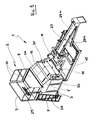
- the structure marked by 1 as a whole which is arranged in front of the bridge 2 and which forms a free volume arranged to receive in its center and maintain the bucket 6 to clean, is attached to at least two of the three elements constituted by the technical cabinet 3, the second settling tank 4 and the clean water tank 5.
- this hooking is performed by means of bolting such as 30 and it is preferably provided on the technical cabinet 3 and on the second decanter 4.
- the gangway 2 is equipped with at least one ladder 7, allowing the companion to wash access to a platform 8, as many gates 9 that there are ladders, and guardrails 10 arranged on all the rest of the periphery of the bridge and whose role is to protect the companion against the risk of falling.
- the bridge 2 overhangs a metal structure 1 which is arranged in front of it and which forms in its center a free volume 11 delimited and arranged by construction to receive and maintain the bucket 6 to clean, preferably in a position where said bucket is in an inclined position so that its opening 12 through which is introduced the concrete is turned towards the bridge 2.
- the free volume 11 of the structure 1 is delimited by different means of the bucket which are separated from each other, namely means 13 arranged in the upper part of the structure, which support and hold the bucket, and means 14 arranged in lower part of the structure and which also support or hold the bucket.
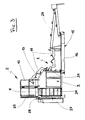
- the structure 1, which thus forms a cradle in which the bucket to be cleaned can be accommodated, is provided to articulate relative to the bridge 2. It can occupy either a working position in which its support means and lower restraint rest on the ground, either a storage position, or transport, shown in dashed lines at the Figure 3 , in which the structure 1 is raised vertically and is then positioned in the vicinity of the bridge 2.
- the structure 1 cradle-shaped overhangs a tank 15 for retention and decantation of wash water, this bin 15 being disposed on the ground, in the vertical structure.
- the tray 15 is equipped with a filter 16 with very large mesh, or a perforated sheet 16, this filter or this sheet 16 being disposed transversely inside the tray.
- the function of this tank is to make a first separation of the concrete residues removed from the bucket by the wash water, the most loaded water, flowing from the chute 17 of the bucket, flowing into the front part of the tank and the least loaded water, which flows from the body of the bucket, pouring into the rear part of the tank.
- the tray 15 may advantageously be provided with a deck 15 ', preferably removable and movable from front to back, on which the standing companion will be able to clean the bottom of the tray.
- This decking 15 ' will also allow the companion to access more easily, in the lower and front areas, to all parts washing the bucket, while securing the washing area.
- the technical cabinet 3 is equipped with a power supply box 18, a lifting pump 19, for pumping the slightly soiled water on the surface of the rear part of the tank 15, which pump is connected to a pipe of Aspiration shown schematically by its grip 20, and a pump equipped with a pressure washing gun of construction equipment shown schematically by its support 21, as it is particularly visible to Figures 6 and 7 , the construction equipment to be washed is either a bucket or a truck top truck whose rear is then placed above the front portion of the tank 15.
- a soiled water treatment unit this treatment unit essentially consisting of a second settling tank 4 and a tank of water. clean water reprocessed 5.
- the second tank 4 rests on the tank of clean water 5, these two tanks are immediately adjacent to the technical cabinet 3, and the assembly thus constituted by the three elements 3, 4 and 5 above is placed under the bridge 2.
- the assembly is placed so as not to overflow the base of the bridge, both on the lateral sides 22 and on the rear side 23 opposite to the one facing the structure 1.
- the left edges of the technical cabinet 3 and the straight edges of the bins 4 and 5 are reinforced by profiles or metal angles such as 24, which constitute extensions. corner posts 25 of the guardrails 10.
- the assembly consisting of the three elements 3, 4 and 5 does not emerge from the bridge 2 and is protected from shocks that could cause vehicles during their maneuvers.
- the height of the technical cabinet 3 will be substantially equal to the height of the lower tank of clean water 5 increased by the height of the upper decantation tank 4 in order, if necessary, to provide additional support for the platform 8.
- the technical cabinet 3 and the upper tray 4 will have, by construction, front faces, respectively 3 'and 4', inclined towards the ground from rear to front, and this always in order to save space since then these two elements may come to fit under the upper holding means 13.
- the clean water tank 5 must be an enclosure protected from any projection. That's why he is highly preferable to place it under the second settling tank 4, the latter constantly protecting it naturally. In addition, this construction will allow the treated water in the tray 4 to flow by simple gravity in the tray 5, while in the opposite case it would be necessary to use an additional pump.
- the clean water tank 5 further comprises: a water intake, which will be connected by a pipe to the support 21, a filter disposed upstream of this pipe, a device such as manual valve, solenoid valve or cap for example , for the emptying of said tank 5 and, advantageously, a water level and a inspection hatch to allow its cleaning, said hatch being located on one of the three accessible free faces of said tank 5, that is to say on the right side 22 or on the rear side 23, or better still on the front side 23 'since then the poorly directed stains during such cleaning will automatically fall into the retention tank 15 instead of spreading on the ground.
- a water intake which will be connected by a pipe to the support 21, a filter disposed upstream of this pipe, a device such as manual valve, solenoid valve or cap for example , for the emptying of said tank 5 and, advantageously, a water level and a inspection hatch to allow its cleaning, said hatch being located on one of the three accessible free faces of said tank 5, that is to say on the right side 22 or on the rear side 23, or better
- the second settling tank 4 is for its part equipped with a separating plate 26, shown in dashed line at the Figure 2 , which sheet will be arranged vertically, preferably parallel to the general direction of the installation, so that from the front of the latter, the companion can more easily access each of the two compartments that it delimits in the tray 4, or at least have a perfect visibility of these two compartments.
- This sheet 26 has the function of separating any formwork oils from soiled washing water to be treated.
- the second settling tank 4 further comprises a device of the manual valve or electrovalve type, for example, for the transfer of the treated water into said tank 4.
- the latter will also optionally be provided with a inspection hatch to allow it to be cleaned. said hatch being located on the right side 22 or on the rear side 23, or better still on the front side 23 ', that is to say on one of its three accessible free faces.
- the installation according to the invention thus allows a complete recycling of washing water. These are recovered in the first holding tank 15, where they are subjected to a first settling. They are then transferred, for those with the least soil, into the second settling tank 4 where they are then subjected to a second settling, to a separation recovery of any formwork oil residues and to a treatment of their pH. . The water thus recycled is then transferred to the clean water tank 5, where it is stored so that it can be used for future washing, except to be discharged into the sewers at the end of the construction site, when all the equipment has been cleaned for one last time.
- the plant according to the invention ensures a reprocessing such that the pH value of the water treated in the second settling tank 4 is within the permissible range of 6, 5 to 8.5 and in any event conforms to the value imposed by the competent local authorities.
- the treated water is put in the sewer, it is certain that this will be done without risk of pollution.
- the treatment unit before each transfer of water from the second settling tank 4 into the clean water tank 5, the treatment unit provides a pH treatment. This operation is carried out without adding acid, unlike previous techniques.
- the treatment unit of the present installation comprises means for injecting CO 2 gas into the washing water contained in the second settling tank 4.
- injection means are comprise a bottle 27 of CO 2 gas and an expansion valve fixed on said bottle and connected by a flexible pipe to a CO 2 diffuser disposed in the bottom of the second settling tank 4, preferably in the middle of this tank, centered with respect to the separating plate 26.
- the bottle 27 of CO 2 gas is supported by a bottle holder 28 itself fixed to the rear of the bins 4 and 5.
- the diffuser 31 shown in FIG. Figure 8 consists of a support plate 32 folded in U, each of the two wings 33 is pierced with orifices 34 whose diameter is greater than the diameter of a porous pipe 35 which will ensure the injection of CO 2 (for example 18 mm for the diameter of the orifices and 16 mm for the diameter of the pipe).
- the U-shaped support plate 32 is placed substantially in the center of the bottom of the second settling tank 4 and the porous pipe 35 is wound in three or four loops in said sheet, as shown in FIG. Figure 8 , using the orifices 34.
- the porous pipe is about three to four meters long. It can be a simple garden hose that lets the CO 2 gas escape freely from the pipe to the liquid to be treated.
- the porous pipe 35 is connected at 36 to the non-porous pipe 37 which feeds it with CO 2 gas from the bottle 27.
- a valve is advantageously arranged at the connection 36 between the two pipes 35 and 37.
- the treatment of dirty water by CO 2 gas injection in the second settling tank 4 is preferably carried out semi-automatically, for example by adjusting the expansion valve at a flow rate of about fifty liters per minute for cycles of each about three minutes. After each gas injection cycle, and also after being checked with a pH paper or pH meter, the pH value of the treated water is well within the range 6.5 8.5, the CO 2 gas cylinder is closed for safety.
- a chute 29 which extends the first settling tank 15 and which is adapted to receive and support any possible outlet pipe of the concrete disposed under the body of the bucket 6 being cleaned.
- This chute being substantially inclined up and down forwards, it will allow the flow and recovery of wash water from the inside of the bucket into the holding tank, while maintaining the dry pipe during the phases of storage of the bucket on the installation to limit its degradation.
- the pipe extending the body of the bucket 6 is too long and extends beyond the front edge of the first bin 15, it is intended to build the chute 29 in two superimposed segments and inverse inclinations, and this has been represented to Figures 1 to 7 .
- the pipe extending the bucket 6 then rests on the upper segment 29a of the chute 29 while the washing water flows from the upper segment 29a in the second lower segment 29b, through the aperture provided at the end of said upper segment 29a, then the second segment 29b in the tray 15.
- frost-free holding device of the installation in order to avoid any deterioration of the equipment, if such an installation is to operate in winter and / or in cold countries.
- Such a device will then include heating ducts around the pumps and around all water circulation pipes.
Landscapes
- Engineering & Computer Science (AREA)
- Mechanical Engineering (AREA)
- Architecture (AREA)
- Water Supply & Treatment (AREA)
- Structural Engineering (AREA)
- Life Sciences & Earth Sciences (AREA)
- Hydrology & Water Resources (AREA)
- Environmental & Geological Engineering (AREA)
- Civil Engineering (AREA)
- Chemical & Material Sciences (AREA)
- Organic Chemistry (AREA)
- Cleaning By Liquid Or Steam (AREA)
- Processing Of Solid Wastes (AREA)
- Fertilizers (AREA)
- Physical Water Treatments (AREA)
- Purification Treatments By Anaerobic Or Anaerobic And Aerobic Bacteria Or Animals (AREA)
Applications Claiming Priority (1)
| Application Number | Priority Date | Filing Date | Title |
|---|---|---|---|
| FR0900795A FR2942417B1 (fr) | 2009-02-20 | 2009-02-20 | Installation de lavage des materiels de chantier et de traitement, suivi d'un recyclage, des eaux utilisees pour un tel lavage |
Publications (2)
| Publication Number | Publication Date |
|---|---|
| EP2221434A1 true EP2221434A1 (de) | 2010-08-25 |
| EP2221434B1 EP2221434B1 (de) | 2011-02-23 |
Family
ID=41010886
Family Applications (1)
| Application Number | Title | Priority Date | Filing Date |
|---|---|---|---|
| EP10290088A Active EP2221434B1 (de) | 2009-02-20 | 2010-02-22 | Waschanlage für Baustellen- und Aufbereitungsmaterial, gefolgt von einem Recycling des Brauchwassers für einen solchen Waschvorgang |
Country Status (6)
| Country | Link |
|---|---|
| EP (1) | EP2221434B1 (de) |
| AT (1) | ATE499495T1 (de) |
| DE (1) | DE602010000005D1 (de) |
| ES (1) | ES2361722T3 (de) |
| FR (1) | FR2942417B1 (de) |
| PT (1) | PT2221434E (de) |
Cited By (5)
| Publication number | Priority date | Publication date | Assignee | Title |
|---|---|---|---|---|
| WO2013124639A1 (en) * | 2012-02-21 | 2013-08-29 | Siltbuster Limited | Concrete washout unit and method |
| FR2990936A1 (fr) * | 2012-07-13 | 2013-11-29 | Laurent Topelet | Installation de lavage et de recyclage d'eau chargee de gravats |
| FR3007755A1 (fr) * | 2013-06-28 | 2015-01-02 | Secatol | Station de recyclage des eaux de lavage de materiels de chantier |
| FR3031973A1 (fr) * | 2015-01-23 | 2016-07-29 | Vcf Tp Lyon | Dispositif de traitement des eaux de lavage d'une goulotte de toupie a beton. |
| CN117583345A (zh) * | 2024-01-19 | 2024-02-23 | 上海奔曜科技有限公司 | 器皿清洁装置、器皿清洁模块、配液平台及配液系统 |
Families Citing this family (1)
| Publication number | Priority date | Publication date | Assignee | Title |
|---|---|---|---|---|
| FR3028191A1 (fr) | 2014-11-07 | 2016-05-13 | Secatol | Tour de lavage pour bennes a beton, comprenant des patins de centrage des faces inclinees de ces bennes |
Citations (4)
| Publication number | Priority date | Publication date | Assignee | Title |
|---|---|---|---|---|
| FR2728004A1 (fr) * | 1994-12-13 | 1996-06-14 | Meunier Jean Francis | Plate-forme de lavage pour bennes distributrices a beton |
| EP1464775A1 (de) | 2003-03-31 | 2004-10-06 | Société d'Etude et Construction d'Application de la Tolerie "SECATOL" SA | Waschplattform für Betonkübel |
| US20050145624A1 (en) * | 2003-12-30 | 2005-07-07 | Minegar Peter J. | Construction residue transport system |
| FR2913894A1 (fr) * | 2007-03-19 | 2008-09-26 | Air Vibration Services Sarl | Bac de decantation pour benne a beton |
-
2009
- 2009-02-20 FR FR0900795A patent/FR2942417B1/fr not_active Expired - Fee Related
-
2010
- 2010-02-22 ES ES10290088T patent/ES2361722T3/es active Active
- 2010-02-22 EP EP10290088A patent/EP2221434B1/de active Active
- 2010-02-22 PT PT10290088T patent/PT2221434E/pt unknown
- 2010-02-22 DE DE602010000005T patent/DE602010000005D1/de active Active
- 2010-02-22 AT AT10290088T patent/ATE499495T1/de not_active IP Right Cessation
Patent Citations (4)
| Publication number | Priority date | Publication date | Assignee | Title |
|---|---|---|---|---|
| FR2728004A1 (fr) * | 1994-12-13 | 1996-06-14 | Meunier Jean Francis | Plate-forme de lavage pour bennes distributrices a beton |
| EP1464775A1 (de) | 2003-03-31 | 2004-10-06 | Société d'Etude et Construction d'Application de la Tolerie "SECATOL" SA | Waschplattform für Betonkübel |
| US20050145624A1 (en) * | 2003-12-30 | 2005-07-07 | Minegar Peter J. | Construction residue transport system |
| FR2913894A1 (fr) * | 2007-03-19 | 2008-09-26 | Air Vibration Services Sarl | Bac de decantation pour benne a beton |
Cited By (7)
| Publication number | Priority date | Publication date | Assignee | Title |
|---|---|---|---|---|
| WO2013124639A1 (en) * | 2012-02-21 | 2013-08-29 | Siltbuster Limited | Concrete washout unit and method |
| FR2990936A1 (fr) * | 2012-07-13 | 2013-11-29 | Laurent Topelet | Installation de lavage et de recyclage d'eau chargee de gravats |
| EP2684848A1 (de) * | 2012-07-13 | 2014-01-15 | Laurent Topelet | Vorrichtung zum Waschen und Rückführen von Baustellenabwasser |
| FR3007755A1 (fr) * | 2013-06-28 | 2015-01-02 | Secatol | Station de recyclage des eaux de lavage de materiels de chantier |
| FR3031973A1 (fr) * | 2015-01-23 | 2016-07-29 | Vcf Tp Lyon | Dispositif de traitement des eaux de lavage d'une goulotte de toupie a beton. |
| CN117583345A (zh) * | 2024-01-19 | 2024-02-23 | 上海奔曜科技有限公司 | 器皿清洁装置、器皿清洁模块、配液平台及配液系统 |
| CN117583345B (zh) * | 2024-01-19 | 2024-04-26 | 上海奔曜科技有限公司 | 器皿清洁装置、器皿清洁模块、配液平台及配液系统 |
Also Published As
| Publication number | Publication date |
|---|---|
| FR2942417A1 (fr) | 2010-08-27 |
| DE602010000005D1 (de) | 2011-04-07 |
| FR2942417B1 (fr) | 2011-02-11 |
| EP2221434B1 (de) | 2011-02-23 |
| PT2221434E (pt) | 2011-05-23 |
| ES2361722T3 (es) | 2011-06-21 |
| ATE499495T1 (de) | 2011-03-15 |
Similar Documents
| Publication | Publication Date | Title |
|---|---|---|
| EP2221434B1 (de) | Waschanlage für Baustellen- und Aufbereitungsmaterial, gefolgt von einem Recycling des Brauchwassers für einen solchen Waschvorgang | |
| CA2314542A1 (fr) | Unite mobile de lavage et de recuperation d'eaux usees | |
| JPH11216435A (ja) | 閉ループ圧力洗浄システム及び方法 | |
| US9943982B2 (en) | Concrete mixing transport truck chute washout system | |
| EP2684848B1 (de) | Vorrichtung zum Waschen und Rückführen von Baustellenabwasser | |
| US9937636B2 (en) | Concrete mixing transport truck chute washout system | |
| JP5406404B1 (ja) | 洗浄選別装置 | |
| FR3007755B1 (fr) | Station de recyclage des eaux de lavage de materiels de chantier | |
| EP3529021A1 (de) | Kompakte recycling-vorrichtung für kunststoffabfälle | |
| FR2913895A1 (fr) | Bac de decantation pour benne a beton | |
| FR3094175A1 (fr) | Dispositif de lavage permettant de laver l’ensemble de la carrosserie extérieure, le bas et les lames des robots tondeuses | |
| FR2949107A1 (fr) | Dispositif pour accueillir un conteneur de collecte de dechets au moins partiellement enterre | |
| FR2930962A1 (fr) | Plate-forme de nettoyage de materiel de chantier de construction | |
| FR3031100A1 (fr) | Dispositif de chantier perfectionne pour le recyclage d’une eau de lavage | |
| JP3970271B2 (ja) | 洗浄装置 | |
| US20200276623A1 (en) | Apparatus, system and method for cleaning a wheelbarrow | |
| JP4570401B2 (ja) | 沈砂池における揚砂洗浄搬送システム | |
| EP0769248B1 (de) | Vorrichtung zum Waschen von Fischen und Fisch-Träger für diese Vorrichtung | |
| FR2932465A1 (fr) | Dispositif de plate-forme d'accueil pour le vidage et le lavage des vehicules de nettoiement des chaussees | |
| FR2810010A1 (fr) | Installation de nettoyage de coques de bateaux | |
| FR2907111A1 (fr) | Dispositif de recyclage d'eau par separation dynamique des boues, et installation de lavage de l'eau equipee d'un tel dispositif | |
| EP0965542A2 (de) | Waschanlage für Müllbehälter | |
| FR2858286A1 (fr) | Installation transportable de lavage de vehicules routiers et de chantiers de travaux publics | |
| FR3080342A1 (fr) | Aire de nettoyage de vehicules | |
| EP2924160B1 (de) | Vorrichtung zum Waschen von textilen Artikeln großer Abmessungen |
Legal Events
| Date | Code | Title | Description |
|---|---|---|---|
| PUAI | Public reference made under article 153(3) epc to a published international application that has entered the european phase |
Free format text: ORIGINAL CODE: 0009012 |
|
| 17P | Request for examination filed |
Effective date: 20100301 |
|
| AK | Designated contracting states |
Kind code of ref document: A1 Designated state(s): AT BE BG CH CY CZ DE DK EE ES FI FR GB GR HR HU IE IS IT LI LT LU LV MC MK MT NL NO PL PT RO SE SI SK SM TR |
|
| AX | Request for extension of the european patent |
Extension state: AL BA RS |
|
| GRAP | Despatch of communication of intention to grant a patent |
Free format text: ORIGINAL CODE: EPIDOSNIGR1 |
|
| RIC1 | Information provided on ipc code assigned before grant |
Ipc: E04G 21/02 20060101AFI20101025BHEP |
|
| GRAS | Grant fee paid |
Free format text: ORIGINAL CODE: EPIDOSNIGR3 |
|
| GRAA | (expected) grant |
Free format text: ORIGINAL CODE: 0009210 |
|
| AK | Designated contracting states |
Kind code of ref document: B1 Designated state(s): AT BE BG CH CY CZ DE DK EE ES FI FR GB GR HR HU IE IS IT LI LT LU LV MC MK MT NL NO PL PT RO SE SI SK SM TR |
|
| REG | Reference to a national code |
Ref country code: GB Ref legal event code: FG4D Free format text: NOT ENGLISH |
|
| REG | Reference to a national code |
Ref country code: CH Ref legal event code: EP |
|
| REG | Reference to a national code |
Ref country code: IE Ref legal event code: FG4D Free format text: LANGUAGE OF EP DOCUMENT: FRENCH |
|
| REF | Corresponds to: |
Ref document number: 602010000005 Country of ref document: DE Date of ref document: 20110407 Kind code of ref document: P |
|
| REG | Reference to a national code |
Ref country code: DE Ref legal event code: R096 Ref document number: 602010000005 Country of ref document: DE Effective date: 20110407 |
|
| REG | Reference to a national code |
Ref country code: PT Ref legal event code: SC4A Free format text: AVAILABILITY OF NATIONAL TRANSLATION Effective date: 20110513 |
|
| REG | Reference to a national code |
Ref country code: CH Ref legal event code: NV Representative=s name: INTERPAT LAW AG |
|
| REG | Reference to a national code |
Ref country code: NL Ref legal event code: T3 |
|
| REG | Reference to a national code |
Ref country code: ES Ref legal event code: FG2A Ref document number: 2361722 Country of ref document: ES Kind code of ref document: T3 Effective date: 20110621 |
|
| LTIE | Lt: invalidation of european patent or patent extension |
Effective date: 20110223 |
|
| PG25 | Lapsed in a contracting state [announced via postgrant information from national office to epo] |
Ref country code: SE Free format text: LAPSE BECAUSE OF FAILURE TO SUBMIT A TRANSLATION OF THE DESCRIPTION OR TO PAY THE FEE WITHIN THE PRESCRIBED TIME-LIMIT Effective date: 20110223 Ref country code: GR Free format text: LAPSE BECAUSE OF FAILURE TO SUBMIT A TRANSLATION OF THE DESCRIPTION OR TO PAY THE FEE WITHIN THE PRESCRIBED TIME-LIMIT Effective date: 20110524 Ref country code: NO Free format text: LAPSE BECAUSE OF FAILURE TO SUBMIT A TRANSLATION OF THE DESCRIPTION OR TO PAY THE FEE WITHIN THE PRESCRIBED TIME-LIMIT Effective date: 20110523 Ref country code: LV Free format text: LAPSE BECAUSE OF FAILURE TO SUBMIT A TRANSLATION OF THE DESCRIPTION OR TO PAY THE FEE WITHIN THE PRESCRIBED TIME-LIMIT Effective date: 20110223 Ref country code: LT Free format text: LAPSE BECAUSE OF FAILURE TO SUBMIT A TRANSLATION OF THE DESCRIPTION OR TO PAY THE FEE WITHIN THE PRESCRIBED TIME-LIMIT Effective date: 20110223 |
|
| PG25 | Lapsed in a contracting state [announced via postgrant information from national office to epo] |
Ref country code: BG Free format text: LAPSE BECAUSE OF FAILURE TO SUBMIT A TRANSLATION OF THE DESCRIPTION OR TO PAY THE FEE WITHIN THE PRESCRIBED TIME-LIMIT Effective date: 20110523 Ref country code: SI Free format text: LAPSE BECAUSE OF FAILURE TO SUBMIT A TRANSLATION OF THE DESCRIPTION OR TO PAY THE FEE WITHIN THE PRESCRIBED TIME-LIMIT Effective date: 20110223 Ref country code: FI Free format text: LAPSE BECAUSE OF FAILURE TO SUBMIT A TRANSLATION OF THE DESCRIPTION OR TO PAY THE FEE WITHIN THE PRESCRIBED TIME-LIMIT Effective date: 20110223 Ref country code: AT Free format text: LAPSE BECAUSE OF FAILURE TO SUBMIT A TRANSLATION OF THE DESCRIPTION OR TO PAY THE FEE WITHIN THE PRESCRIBED TIME-LIMIT Effective date: 20110223 Ref country code: CY Free format text: LAPSE BECAUSE OF FAILURE TO SUBMIT A TRANSLATION OF THE DESCRIPTION OR TO PAY THE FEE WITHIN THE PRESCRIBED TIME-LIMIT Effective date: 20110223 |
|
| PG25 | Lapsed in a contracting state [announced via postgrant information from national office to epo] |
Ref country code: EE Free format text: LAPSE BECAUSE OF FAILURE TO SUBMIT A TRANSLATION OF THE DESCRIPTION OR TO PAY THE FEE WITHIN THE PRESCRIBED TIME-LIMIT Effective date: 20110223 Ref country code: DK Free format text: LAPSE BECAUSE OF FAILURE TO SUBMIT A TRANSLATION OF THE DESCRIPTION OR TO PAY THE FEE WITHIN THE PRESCRIBED TIME-LIMIT Effective date: 20110223 |
|
| PG25 | Lapsed in a contracting state [announced via postgrant information from national office to epo] |
Ref country code: SK Free format text: LAPSE BECAUSE OF FAILURE TO SUBMIT A TRANSLATION OF THE DESCRIPTION OR TO PAY THE FEE WITHIN THE PRESCRIBED TIME-LIMIT Effective date: 20110223 Ref country code: RO Free format text: LAPSE BECAUSE OF FAILURE TO SUBMIT A TRANSLATION OF THE DESCRIPTION OR TO PAY THE FEE WITHIN THE PRESCRIBED TIME-LIMIT Effective date: 20110223 Ref country code: CZ Free format text: LAPSE BECAUSE OF FAILURE TO SUBMIT A TRANSLATION OF THE DESCRIPTION OR TO PAY THE FEE WITHIN THE PRESCRIBED TIME-LIMIT Effective date: 20110223 |
|
| PLBE | No opposition filed within time limit |
Free format text: ORIGINAL CODE: 0009261 |
|
| STAA | Information on the status of an ep patent application or granted ep patent |
Free format text: STATUS: NO OPPOSITION FILED WITHIN TIME LIMIT |
|
| PG25 | Lapsed in a contracting state [announced via postgrant information from national office to epo] |
Ref country code: HR Free format text: LAPSE BECAUSE OF FAILURE TO SUBMIT A TRANSLATION OF THE DESCRIPTION OR TO PAY THE FEE WITHIN THE PRESCRIBED TIME-LIMIT Effective date: 20110907 |
|
| 26N | No opposition filed |
Effective date: 20111124 |
|
| PG25 | Lapsed in a contracting state [announced via postgrant information from national office to epo] |
Ref country code: PL Free format text: LAPSE BECAUSE OF FAILURE TO SUBMIT A TRANSLATION OF THE DESCRIPTION OR TO PAY THE FEE WITHIN THE PRESCRIBED TIME-LIMIT Effective date: 20110223 |
|
| REG | Reference to a national code |
Ref country code: DE Ref legal event code: R097 Ref document number: 602010000005 Country of ref document: DE Effective date: 20111124 |
|
| PG25 | Lapsed in a contracting state [announced via postgrant information from national office to epo] |
Ref country code: MK Free format text: LAPSE BECAUSE OF FAILURE TO SUBMIT A TRANSLATION OF THE DESCRIPTION OR TO PAY THE FEE WITHIN THE PRESCRIBED TIME-LIMIT Effective date: 20110223 |
|
| PG25 | Lapsed in a contracting state [announced via postgrant information from national office to epo] |
Ref country code: MT Free format text: LAPSE BECAUSE OF FAILURE TO SUBMIT A TRANSLATION OF THE DESCRIPTION OR TO PAY THE FEE WITHIN THE PRESCRIBED TIME-LIMIT Effective date: 20110223 |
|
| PG25 | Lapsed in a contracting state [announced via postgrant information from national office to epo] |
Ref country code: HR Free format text: LAPSE BECAUSE OF FAILURE TO SUBMIT A TRANSLATION OF THE DESCRIPTION OR TO PAY THE FEE WITHIN THE PRESCRIBED TIME-LIMIT Effective date: 20110223 |
|
| PG25 | Lapsed in a contracting state [announced via postgrant information from national office to epo] |
Ref country code: TR Free format text: LAPSE BECAUSE OF FAILURE TO SUBMIT A TRANSLATION OF THE DESCRIPTION OR TO PAY THE FEE WITHIN THE PRESCRIBED TIME-LIMIT Effective date: 20110223 |
|
| PG25 | Lapsed in a contracting state [announced via postgrant information from national office to epo] |
Ref country code: SM Free format text: LAPSE BECAUSE OF FAILURE TO SUBMIT A TRANSLATION OF THE DESCRIPTION OR TO PAY THE FEE WITHIN THE PRESCRIBED TIME-LIMIT Effective date: 20110223 |
|
| PG25 | Lapsed in a contracting state [announced via postgrant information from national office to epo] |
Ref country code: HU Free format text: LAPSE BECAUSE OF FAILURE TO SUBMIT A TRANSLATION OF THE DESCRIPTION OR TO PAY THE FEE WITHIN THE PRESCRIBED TIME-LIMIT Effective date: 20100222 |
|
| REG | Reference to a national code |
Ref country code: FR Ref legal event code: PLFP Year of fee payment: 7 |
|
| PG25 | Lapsed in a contracting state [announced via postgrant information from national office to epo] |
Ref country code: IS Free format text: LAPSE BECAUSE OF FAILURE TO SUBMIT A TRANSLATION OF THE DESCRIPTION OR TO PAY THE FEE WITHIN THE PRESCRIBED TIME-LIMIT Effective date: 20110223 |
|
| REG | Reference to a national code |
Ref country code: FR Ref legal event code: PLFP Year of fee payment: 8 |
|
| REG | Reference to a national code |
Ref country code: FR Ref legal event code: PLFP Year of fee payment: 9 |
|
| PGFP | Annual fee paid to national office [announced via postgrant information from national office to epo] |
Ref country code: IE Payment date: 20180221 Year of fee payment: 9 Ref country code: PT Payment date: 20180214 Year of fee payment: 9 |
|
| PGFP | Annual fee paid to national office [announced via postgrant information from national office to epo] |
Ref country code: ES Payment date: 20180328 Year of fee payment: 9 |
|
| PG25 | Lapsed in a contracting state [announced via postgrant information from national office to epo] |
Ref country code: PT Free format text: LAPSE BECAUSE OF NON-PAYMENT OF DUE FEES Effective date: 20190822 |
|
| REG | Reference to a national code |
Ref country code: IE Ref legal event code: MM4A |
|
| PG25 | Lapsed in a contracting state [announced via postgrant information from national office to epo] |
Ref country code: IE Free format text: LAPSE BECAUSE OF NON-PAYMENT OF DUE FEES Effective date: 20190222 |
|
| REG | Reference to a national code |
Ref country code: ES Ref legal event code: FD2A Effective date: 20200331 |
|
| PG25 | Lapsed in a contracting state [announced via postgrant information from national office to epo] |
Ref country code: ES Free format text: LAPSE BECAUSE OF NON-PAYMENT OF DUE FEES Effective date: 20190223 |
|
| PGFP | Annual fee paid to national office [announced via postgrant information from national office to epo] |
Ref country code: FR Payment date: 20230227 Year of fee payment: 14 |
|
| PGFP | Annual fee paid to national office [announced via postgrant information from national office to epo] |
Ref country code: IT Payment date: 20230221 Year of fee payment: 14 Ref country code: BE Payment date: 20230216 Year of fee payment: 14 |
|
| P01 | Opt-out of the competence of the unified patent court (upc) registered |
Effective date: 20230606 |
|
| PGFP | Annual fee paid to national office [announced via postgrant information from national office to epo] |
Ref country code: LU Payment date: 20240220 Year of fee payment: 15 |
|
| PGFP | Annual fee paid to national office [announced via postgrant information from national office to epo] |
Ref country code: NL Payment date: 20240202 Year of fee payment: 15 |
|
| PGFP | Annual fee paid to national office [announced via postgrant information from national office to epo] |
Ref country code: MC Payment date: 20240226 Year of fee payment: 15 |
|
| PGFP | Annual fee paid to national office [announced via postgrant information from national office to epo] |
Ref country code: DE Payment date: 20240227 Year of fee payment: 15 Ref country code: GB Payment date: 20240201 Year of fee payment: 15 Ref country code: CH Payment date: 20240301 Year of fee payment: 15 |