EP2221434A1 - Facility for washing plant machinery and for treating the water used for such washing process, followed by recycling same - Google Patents
Facility for washing plant machinery and for treating the water used for such washing process, followed by recycling same Download PDFInfo
- Publication number
- EP2221434A1 EP2221434A1 EP10290088A EP10290088A EP2221434A1 EP 2221434 A1 EP2221434 A1 EP 2221434A1 EP 10290088 A EP10290088 A EP 10290088A EP 10290088 A EP10290088 A EP 10290088A EP 2221434 A1 EP2221434 A1 EP 2221434A1
- Authority
- EP
- European Patent Office
- Prior art keywords
- water
- tank
- washing
- settling tank
- installation according
- Prior art date
- Legal status (The legal status is an assumption and is not a legal conclusion. Google has not performed a legal analysis and makes no representation as to the accuracy of the status listed.)
- Granted
Links
- XLYOFNOQVPJJNP-UHFFFAOYSA-N water Substances O XLYOFNOQVPJJNP-UHFFFAOYSA-N 0.000 title claims abstract description 129
- 238000005406 washing Methods 0.000 title claims abstract description 65
- 238000004064 recycling Methods 0.000 title claims description 6
- 238000009434 installation Methods 0.000 claims abstract description 49
- 238000004140 cleaning Methods 0.000 claims description 10
- 230000014759 maintenance of location Effects 0.000 claims description 7
- 238000002347 injection Methods 0.000 claims description 6
- 239000007924 injection Substances 0.000 claims description 6
- 238000005086 pumping Methods 0.000 claims description 6
- 238000007689 inspection Methods 0.000 claims description 5
- 238000011084 recovery Methods 0.000 claims description 5
- 238000005520 cutting process Methods 0.000 claims description 4
- 239000003921 oil Substances 0.000 claims description 4
- 238000000926 separation method Methods 0.000 claims description 4
- 238000003860 storage Methods 0.000 claims description 4
- 230000015556 catabolic process Effects 0.000 claims description 3
- 238000006731 degradation reaction Methods 0.000 claims description 3
- 238000012545 processing Methods 0.000 claims description 3
- 238000011144 upstream manufacturing Methods 0.000 claims description 3
- 238000009987 spinning Methods 0.000 claims description 2
- CURLTUGMZLYLDI-UHFFFAOYSA-N Carbon dioxide Chemical compound O=C=O CURLTUGMZLYLDI-UHFFFAOYSA-N 0.000 abstract 4
- 229910002092 carbon dioxide Inorganic materials 0.000 abstract 2
- 239000001569 carbon dioxide Substances 0.000 abstract 2
- 239000013505 freshwater Substances 0.000 abstract 2
- 238000010276 construction Methods 0.000 description 26
- 238000012958 reprocessing Methods 0.000 description 8
- 239000000463 material Substances 0.000 description 5
- 230000033228 biological regulation Effects 0.000 description 4
- 238000010908 decantation Methods 0.000 description 4
- 230000006866 deterioration Effects 0.000 description 3
- 239000007788 liquid Substances 0.000 description 3
- 239000002184 metal Substances 0.000 description 3
- 238000004062 sedimentation Methods 0.000 description 3
- 206010040560 shock Diseases 0.000 description 3
- 230000035939 shock Effects 0.000 description 3
- 239000002699 waste material Substances 0.000 description 3
- 239000010419 fine particle Substances 0.000 description 2
- 238000009415 formwork Methods 0.000 description 2
- 239000002245 particle Substances 0.000 description 2
- 238000003892 spreading Methods 0.000 description 2
- 239000000725 suspension Substances 0.000 description 2
- 239000002351 wastewater Substances 0.000 description 2
- 239000003643 water by type Substances 0.000 description 2
- 206010039740 Screaming Diseases 0.000 description 1
- 239000002253 acid Substances 0.000 description 1
- 230000001934 delay Effects 0.000 description 1
- 238000001035 drying Methods 0.000 description 1
- 238000003912 environmental pollution Methods 0.000 description 1
- 230000005484 gravity Effects 0.000 description 1
- 239000003673 groundwater Substances 0.000 description 1
- 238000010438 heat treatment Methods 0.000 description 1
- 238000000034 method Methods 0.000 description 1
- 238000002156 mixing Methods 0.000 description 1
- 238000006386 neutralization reaction Methods 0.000 description 1
- 239000002689 soil Substances 0.000 description 1
- 239000007921 spray Substances 0.000 description 1
- 239000002352 surface water Substances 0.000 description 1
- 230000009182 swimming Effects 0.000 description 1
Images


Classifications
-
- E—FIXED CONSTRUCTIONS
- E04—BUILDING
- E04G—SCAFFOLDING; FORMS; SHUTTERING; BUILDING IMPLEMENTS OR AIDS, OR THEIR USE; HANDLING BUILDING MATERIALS ON THE SITE; REPAIRING, BREAKING-UP OR OTHER WORK ON EXISTING BUILDINGS
- E04G21/00—Preparing, conveying, or working-up building materials or building elements in situ; Other devices or measures for constructional work
- E04G21/02—Conveying or working-up concrete or similar masses able to be heaped or cast
- E04G21/025—Buckets specially adapted for use with concrete
-
- B—PERFORMING OPERATIONS; TRANSPORTING
- B08—CLEANING
- B08B—CLEANING IN GENERAL; PREVENTION OF FOULING IN GENERAL
- B08B17/00—Methods preventing fouling
- B08B17/02—Preventing deposition of fouling or of dust
- B08B17/06—Preventing deposition of fouling or of dust by giving articles subject to fouling a special shape or arrangement
- B08B17/065—Preventing deposition of fouling or of dust by giving articles subject to fouling a special shape or arrangement the surface having a microscopic surface pattern to achieve the same effect as a lotus flower
-
- B—PERFORMING OPERATIONS; TRANSPORTING
- B08—CLEANING
- B08B—CLEANING IN GENERAL; PREVENTION OF FOULING IN GENERAL
- B08B3/00—Cleaning by methods involving the use or presence of liquid or steam
- B08B3/04—Cleaning involving contact with liquid
- B08B3/10—Cleaning involving contact with liquid with additional treatment of the liquid or of the object being cleaned, e.g. by heat, by electricity or by vibration
- B08B3/14—Removing waste, e.g. labels, from cleaning liquid; Regenerating cleaning liquids
-
- B—PERFORMING OPERATIONS; TRANSPORTING
- B08—CLEANING
- B08B—CLEANING IN GENERAL; PREVENTION OF FOULING IN GENERAL
- B08B9/00—Cleaning hollow articles by methods or apparatus specially adapted thereto
- B08B9/08—Cleaning containers, e.g. tanks
- B08B9/0821—Handling or manipulating containers, e.g. moving or rotating containers in cleaning devices, conveying to or from cleaning devices
- B08B9/0826—Handling or manipulating containers, e.g. moving or rotating containers in cleaning devices, conveying to or from cleaning devices the containers being brought to the cleaning device
-
- B—PERFORMING OPERATIONS; TRANSPORTING
- B08—CLEANING
- B08B—CLEANING IN GENERAL; PREVENTION OF FOULING IN GENERAL
- B08B9/00—Cleaning hollow articles by methods or apparatus specially adapted thereto
- B08B9/08—Cleaning containers, e.g. tanks
- B08B9/093—Cleaning containers, e.g. tanks by the force of jets or sprays
-
- C—CHEMISTRY; METALLURGY
- C02—TREATMENT OF WATER, WASTE WATER, SEWAGE, OR SLUDGE
- C02F—TREATMENT OF WATER, WASTE WATER, SEWAGE, OR SLUDGE
- C02F1/00—Treatment of water, waste water, or sewage
- C02F1/66—Treatment of water, waste water, or sewage by neutralisation; pH adjustment
-
- B—PERFORMING OPERATIONS; TRANSPORTING
- B01—PHYSICAL OR CHEMICAL PROCESSES OR APPARATUS IN GENERAL
- B01D—SEPARATION
- B01D21/00—Separation of suspended solid particles from liquids by sedimentation
- B01D21/02—Settling tanks with single outlets for the separated liquid
-
- C—CHEMISTRY; METALLURGY
- C02—TREATMENT OF WATER, WASTE WATER, SEWAGE, OR SLUDGE
- C02F—TREATMENT OF WATER, WASTE WATER, SEWAGE, OR SLUDGE
- C02F1/00—Treatment of water, waste water, or sewage
- C02F2001/007—Processes including a sedimentation step
-
- C—CHEMISTRY; METALLURGY
- C02—TREATMENT OF WATER, WASTE WATER, SEWAGE, OR SLUDGE
- C02F—TREATMENT OF WATER, WASTE WATER, SEWAGE, OR SLUDGE
- C02F2103/00—Nature of the water, waste water, sewage or sludge to be treated
- C02F2103/001—Runoff or storm water
Definitions
- the present invention relates to a combined installation (a) washing the skips and troughs of trucks spinning top and (b) treatment, followed by recycling, wash water such equipment.
- the short drying time of the concrete residues would not allow to transport the washing equipment from the sites to a unit equipped for the reprocessing of washing water.
- bins are generally associated with a gangway equipped with one and usually two access ladders for the companion in charge of washing, as many gates as there are ladders, and a guardrail arranged on everything the rest of the periphery of the bridge and whose role is to protect the companion against the risk of falling.
- the bridge On site, the bridge is positioned along any side of the tray and, most often, it is attached to it to ensure a perfect stability.
- the truck As for the washing of a truck top, the truck is of course then oriented so that the top overhangs the tank, it is performed by the companion perched on the bridge or using a pressure washing gun fed in water by a pump which takes the water on the surface of the tank, that is to say the least polluted water possible, the washing thus being done in closed circuit, either by means of a pipe of truck specific spray, which projects clean water from a tank also associated with the truck, the water thus fed by the truck flowing after washing in the tank and causing the water level to rise in the bin.
- the Spin trucks are never equipped with a device for recovering polluted water, let alone a device for treating such water.
- the applicant company of the present patent application has designed a washing facility of construction equipment (skips and trucks spindle) constituting a significant advance compared to simple bins.
- This installation described in European Patent No. 1,464,775 published on October 6, 2004 , consists of a gateway of the kind mentioned above, said gateway having the particularity of overhanging a metal structure which is arranged in front of it and which forms in its center a free volume arranged to receive and maintain the bucket to be cleaned, and whatever the type of skip concerned.
- the bucket rests in an inclined position in this cradle-shaped structure such that its upper opening through which the concrete is introduced is turned towards the bridge, a provision which obviously facilitates the washing of the bucket by the companion.
- the cradle-shaped structure itself overhangs a holding tank and settling of washing water to prevent them, stained, do not spread on the floor of the site.
- the applicant company of the present patent application has subsequently perfected such an installation by adding a first unit for treating and recycling the washing water filling its retention and settling tank, this as well to improve the quality of the washing of the construction equipment that to avoid too frequent emptying operations of the tank and routing of dirty water to a concrete plant whose mission will be to reprocess such dirty water.
- the invention thus improved comprises a technical cabinet equipped with a power supply box, a washing pump equipped with a pressurized washing gun, a lifting pump, for pumping dirty water into the water. retention and settling tank, connected to a suction pipe, and a washing water treatment unit arranged between the lifting pump and the washing gun.
- the present invention proposes to overcome all these drawbacks and, to this end, it relates to an installation of the last aforementioned type which is remarkable in that it further comprises a second settling tank disposed under the bridge and a tray of clean water reprocessed arranged under the second settling tank, the technical cabinet is also placed under the bridge, next to the second settling tank and the clean water tank.
- the set composed of the second settling tank, the clean water tank and the technical cabinet which is very compact, is perfectly protected against the risk of shocks since it is arranged under the bridge and overflows the base of the latter neither on the lateral sides, nor on the back side, opposite to that which receives the structure in the form of cradle.
- the second settling tank, the clean water tank and the technical cabinet also overflow the gangway forward and fit partly under the structure arranged to receive and maintain the bucket to be cleaned.
- This construction variant thus makes it possible to exploit all the existing free volume under the bridge and under the cradle-shaped structure, while maintaining the same compactness character to the whole "second settling tank + tank of clean water + technical cabinet "and keeping the same guarantee of protection against shocks.
- the free volume available under the cradle-shaped structure it is obvious that it becomes possible to provide for the use of a second settling tank and a tank of clean water of possible capacity. more important.
- the height of the technical cabinet is substantially equal to the height of the tank of clean water increased by the height of the second settling tank.
- the plant according to the invention is also remarkable in that its treatment unit allows a treatment of the pH before each transfer of water from the second settling tank into the clean water tank in order to reduce the pH value of the water in the allowable range from 6.5 to 8.5.
- the treatment unit comprises means for injecting CO 2 gas into the washing water contained in the second settling tank to treat the pH.
- the installation comprises a bottle of CO 2 gas and an expansion valve fixed on said bottle and connected by a flexible pipe to a CO 2 diffuser disposed in the bottom of the second settling tank, of preferably in the center of this tray.
- the installation also comprises a bottle holder adapted to receive and fix the CO 2 gas bottle at the rear of the second settling tank and the clean water tank.
- the improved treatment by CO 2 gas injection is performed semi-automatically, for example by adjusting the expander at a flow rate of about 50 liters per minute for cycles of each about 3 minutes.
- the first settling tank of the installation according to the invention is provided with a removable decking allowing the companion to access all parts washing the bucket while securing the washing area.
- the first settling tank of the installation according to the invention is extended towards the front of a chute adapted to receive and support a possible concrete flow pipe disposed under the body of the bucket being cleaned, this chute being substantially inclined to allow the flow and recovery of wash water from the inside of the bucket in the holding tank, while keeping the pipe dry during the storage phases of the bucket on the installation to limit its degradation.
- the second settling tank is equipped with: a separation plate arranged vertically, making it possible to separating the possible oils from the water to be treated, a device of the manual valve type, electro-valve for example, for transferring water from said second settling tank into the clean water tank, a device of the manual valve type , electro-valve, cap for example, for the emptying of the second settling tank, and possibly a hatch, for cleaning said second settling tank, which inspection hatch is located on one of the accessible free faces of the last.
- a separation plate arranged vertically, making it possible to separating the possible oils from the water to be treated
- a device of the manual valve type electro-valve for example, for transferring water from said second settling tank into the clean water tank
- a device of the manual valve type electro-valve, cap for example, for the emptying of the second settling tank, and possibly a hatch, for cleaning said second settling tank, which inspection hatch is located on one of the accessible free faces of the last.
- the clean water tank is advantageously made in the form of an enclosure protected from any projection, said tank further comprising: a water intake, a filter arranged upstream of a pump equipped with a pipe leading to the pressure washing gun, a device of the manual valve type, electrovalve, cap for example, for emptying the tank of clean water, and possibly a water level and a trap door , for cleaning said clean water tank, located on one of the accessible free faces thereof.
- the technical cabinet can advantageously include: the lifting pump pumping the dirty water in the first settling tank, a suction pipe of such dirty water, possibly a strainer, possibly a float to cut the power supply pump in the case where the water level in the first settling tank is too low, a discharge pipe and possibly a timer to limit the use of pumps in time to avoid any deterioration of those -this.
- the technical cabinet may also include a booster equipped with a cleaning lance with a washing pipe, a washing gun and possibly a float to cut the power supply. electric pump in case the water level in the clean water tank is too low.
- the technical cabinet can also include a protection device for all the components of the installation in case of negative external temperatures.
- the structure marked by 1 as a whole which is arranged in front of the bridge 2 and which forms a free volume arranged to receive in its center and maintain the bucket 6 to clean, is attached to at least two of the three elements constituted by the technical cabinet 3, the second settling tank 4 and the clean water tank 5.
- this hooking is performed by means of bolting such as 30 and it is preferably provided on the technical cabinet 3 and on the second decanter 4.
- the gangway 2 is equipped with at least one ladder 7, allowing the companion to wash access to a platform 8, as many gates 9 that there are ladders, and guardrails 10 arranged on all the rest of the periphery of the bridge and whose role is to protect the companion against the risk of falling.
- the bridge 2 overhangs a metal structure 1 which is arranged in front of it and which forms in its center a free volume 11 delimited and arranged by construction to receive and maintain the bucket 6 to clean, preferably in a position where said bucket is in an inclined position so that its opening 12 through which is introduced the concrete is turned towards the bridge 2.
- the free volume 11 of the structure 1 is delimited by different means of the bucket which are separated from each other, namely means 13 arranged in the upper part of the structure, which support and hold the bucket, and means 14 arranged in lower part of the structure and which also support or hold the bucket.
- the structure 1, which thus forms a cradle in which the bucket to be cleaned can be accommodated, is provided to articulate relative to the bridge 2. It can occupy either a working position in which its support means and lower restraint rest on the ground, either a storage position, or transport, shown in dashed lines at the Figure 3 , in which the structure 1 is raised vertically and is then positioned in the vicinity of the bridge 2.
- the structure 1 cradle-shaped overhangs a tank 15 for retention and decantation of wash water, this bin 15 being disposed on the ground, in the vertical structure.
- the tray 15 is equipped with a filter 16 with very large mesh, or a perforated sheet 16, this filter or this sheet 16 being disposed transversely inside the tray.
- the function of this tank is to make a first separation of the concrete residues removed from the bucket by the wash water, the most loaded water, flowing from the chute 17 of the bucket, flowing into the front part of the tank and the least loaded water, which flows from the body of the bucket, pouring into the rear part of the tank.
- the tray 15 may advantageously be provided with a deck 15 ', preferably removable and movable from front to back, on which the standing companion will be able to clean the bottom of the tray.
- This decking 15 ' will also allow the companion to access more easily, in the lower and front areas, to all parts washing the bucket, while securing the washing area.
- the technical cabinet 3 is equipped with a power supply box 18, a lifting pump 19, for pumping the slightly soiled water on the surface of the rear part of the tank 15, which pump is connected to a pipe of Aspiration shown schematically by its grip 20, and a pump equipped with a pressure washing gun of construction equipment shown schematically by its support 21, as it is particularly visible to Figures 6 and 7 , the construction equipment to be washed is either a bucket or a truck top truck whose rear is then placed above the front portion of the tank 15.
- a soiled water treatment unit this treatment unit essentially consisting of a second settling tank 4 and a tank of water. clean water reprocessed 5.
- the second tank 4 rests on the tank of clean water 5, these two tanks are immediately adjacent to the technical cabinet 3, and the assembly thus constituted by the three elements 3, 4 and 5 above is placed under the bridge 2.
- the assembly is placed so as not to overflow the base of the bridge, both on the lateral sides 22 and on the rear side 23 opposite to the one facing the structure 1.
- the left edges of the technical cabinet 3 and the straight edges of the bins 4 and 5 are reinforced by profiles or metal angles such as 24, which constitute extensions. corner posts 25 of the guardrails 10.
- the assembly consisting of the three elements 3, 4 and 5 does not emerge from the bridge 2 and is protected from shocks that could cause vehicles during their maneuvers.
- the height of the technical cabinet 3 will be substantially equal to the height of the lower tank of clean water 5 increased by the height of the upper decantation tank 4 in order, if necessary, to provide additional support for the platform 8.
- the technical cabinet 3 and the upper tray 4 will have, by construction, front faces, respectively 3 'and 4', inclined towards the ground from rear to front, and this always in order to save space since then these two elements may come to fit under the upper holding means 13.
- the clean water tank 5 must be an enclosure protected from any projection. That's why he is highly preferable to place it under the second settling tank 4, the latter constantly protecting it naturally. In addition, this construction will allow the treated water in the tray 4 to flow by simple gravity in the tray 5, while in the opposite case it would be necessary to use an additional pump.
- the clean water tank 5 further comprises: a water intake, which will be connected by a pipe to the support 21, a filter disposed upstream of this pipe, a device such as manual valve, solenoid valve or cap for example , for the emptying of said tank 5 and, advantageously, a water level and a inspection hatch to allow its cleaning, said hatch being located on one of the three accessible free faces of said tank 5, that is to say on the right side 22 or on the rear side 23, or better still on the front side 23 'since then the poorly directed stains during such cleaning will automatically fall into the retention tank 15 instead of spreading on the ground.
- a water intake which will be connected by a pipe to the support 21, a filter disposed upstream of this pipe, a device such as manual valve, solenoid valve or cap for example , for the emptying of said tank 5 and, advantageously, a water level and a inspection hatch to allow its cleaning, said hatch being located on one of the three accessible free faces of said tank 5, that is to say on the right side 22 or on the rear side 23, or better
- the second settling tank 4 is for its part equipped with a separating plate 26, shown in dashed line at the Figure 2 , which sheet will be arranged vertically, preferably parallel to the general direction of the installation, so that from the front of the latter, the companion can more easily access each of the two compartments that it delimits in the tray 4, or at least have a perfect visibility of these two compartments.
- This sheet 26 has the function of separating any formwork oils from soiled washing water to be treated.
- the second settling tank 4 further comprises a device of the manual valve or electrovalve type, for example, for the transfer of the treated water into said tank 4.
- the latter will also optionally be provided with a inspection hatch to allow it to be cleaned. said hatch being located on the right side 22 or on the rear side 23, or better still on the front side 23 ', that is to say on one of its three accessible free faces.
- the installation according to the invention thus allows a complete recycling of washing water. These are recovered in the first holding tank 15, where they are subjected to a first settling. They are then transferred, for those with the least soil, into the second settling tank 4 where they are then subjected to a second settling, to a separation recovery of any formwork oil residues and to a treatment of their pH. . The water thus recycled is then transferred to the clean water tank 5, where it is stored so that it can be used for future washing, except to be discharged into the sewers at the end of the construction site, when all the equipment has been cleaned for one last time.
- the plant according to the invention ensures a reprocessing such that the pH value of the water treated in the second settling tank 4 is within the permissible range of 6, 5 to 8.5 and in any event conforms to the value imposed by the competent local authorities.
- the treated water is put in the sewer, it is certain that this will be done without risk of pollution.
- the treatment unit before each transfer of water from the second settling tank 4 into the clean water tank 5, the treatment unit provides a pH treatment. This operation is carried out without adding acid, unlike previous techniques.
- the treatment unit of the present installation comprises means for injecting CO 2 gas into the washing water contained in the second settling tank 4.
- injection means are comprise a bottle 27 of CO 2 gas and an expansion valve fixed on said bottle and connected by a flexible pipe to a CO 2 diffuser disposed in the bottom of the second settling tank 4, preferably in the middle of this tank, centered with respect to the separating plate 26.
- the bottle 27 of CO 2 gas is supported by a bottle holder 28 itself fixed to the rear of the bins 4 and 5.
- the diffuser 31 shown in FIG. Figure 8 consists of a support plate 32 folded in U, each of the two wings 33 is pierced with orifices 34 whose diameter is greater than the diameter of a porous pipe 35 which will ensure the injection of CO 2 (for example 18 mm for the diameter of the orifices and 16 mm for the diameter of the pipe).
- the U-shaped support plate 32 is placed substantially in the center of the bottom of the second settling tank 4 and the porous pipe 35 is wound in three or four loops in said sheet, as shown in FIG. Figure 8 , using the orifices 34.
- the porous pipe is about three to four meters long. It can be a simple garden hose that lets the CO 2 gas escape freely from the pipe to the liquid to be treated.
- the porous pipe 35 is connected at 36 to the non-porous pipe 37 which feeds it with CO 2 gas from the bottle 27.
- a valve is advantageously arranged at the connection 36 between the two pipes 35 and 37.
- the treatment of dirty water by CO 2 gas injection in the second settling tank 4 is preferably carried out semi-automatically, for example by adjusting the expansion valve at a flow rate of about fifty liters per minute for cycles of each about three minutes. After each gas injection cycle, and also after being checked with a pH paper or pH meter, the pH value of the treated water is well within the range 6.5 8.5, the CO 2 gas cylinder is closed for safety.
- a chute 29 which extends the first settling tank 15 and which is adapted to receive and support any possible outlet pipe of the concrete disposed under the body of the bucket 6 being cleaned.
- This chute being substantially inclined up and down forwards, it will allow the flow and recovery of wash water from the inside of the bucket into the holding tank, while maintaining the dry pipe during the phases of storage of the bucket on the installation to limit its degradation.
- the pipe extending the body of the bucket 6 is too long and extends beyond the front edge of the first bin 15, it is intended to build the chute 29 in two superimposed segments and inverse inclinations, and this has been represented to Figures 1 to 7 .
- the pipe extending the bucket 6 then rests on the upper segment 29a of the chute 29 while the washing water flows from the upper segment 29a in the second lower segment 29b, through the aperture provided at the end of said upper segment 29a, then the second segment 29b in the tray 15.
- frost-free holding device of the installation in order to avoid any deterioration of the equipment, if such an installation is to operate in winter and / or in cold countries.
- Such a device will then include heating ducts around the pumps and around all water circulation pipes.
Landscapes
- Engineering & Computer Science (AREA)
- Mechanical Engineering (AREA)
- Architecture (AREA)
- Water Supply & Treatment (AREA)
- Life Sciences & Earth Sciences (AREA)
- Chemical & Material Sciences (AREA)
- Organic Chemistry (AREA)
- Environmental & Geological Engineering (AREA)
- Hydrology & Water Resources (AREA)
- Civil Engineering (AREA)
- Structural Engineering (AREA)
- Cleaning By Liquid Or Steam (AREA)
- Processing Of Solid Wastes (AREA)
- Fertilizers (AREA)
- Physical Water Treatments (AREA)
- Purification Treatments By Anaerobic Or Anaerobic And Aerobic Bacteria Or Animals (AREA)
Abstract
Description
La présente invention est relative à une installation combinée (a) de lavage des bennes et des goulottes de camions toupie et (b) de traitement, suivi d'un recyclage, des eaux de lavage de tels matériels de chantier.The present invention relates to a combined installation (a) washing the skips and troughs of trucks spinning top and (b) treatment, followed by recycling, wash water such equipment.
On sait qu'il est nécessaire de nettoyer régulièrement les différents matériels qui permettent le transport du béton, notamment les camions toupie qui amènent le béton sur les chantiers et les bennes qui, sur les chantiers à proprement parler, assurent le déversement du béton aux endroits et dans les volumes voulus, et ce afin dans ces deux cas de garantir la durée de vie la plus longue possible à de tels matériels.We know that it is necessary to regularly clean the various materials that allow the transport of concrete, including truck top trucks that bring concrete on construction sites and dumpsters that, on the actual construction sites, ensure the pouring of concrete to places and in the desired volumes, and in these two cases to ensure the longest possible life of such materials.
On sait aussi qu'au contact du béton les eaux utilisées pour le lavage des matériels précités, chargées en laitance, donc souillées, deviennent fortement basiques, leur PH atteignant le plus souvent des valeurs de l'ordre de 12, voire supérieures à 12.It is also known that in contact with concrete the water used for washing the aforementioned materials, laden with laitance, and therefore soiled, become strongly basic, their PH often reaching values of the order of 12, or even greater than 12.
Or, les réglementations récentes -Code de l'environnement, Règlement Sanitaire Départemental- visant à réduire la pollution de l'environnement, et plus particulièrement celle de la nappe phréatique de l'environnement des chantiers, interdisent de nettoyer sur les chantiers les matériels précités en déversant les eaux de lavage souillées sur le sol.However, the recent regulations - Code of the Environment, Departmental Sanitary Regulation - aimed at reducing environmental pollution, and more particularly that of the water table of the environment of construction sites, prohibit cleaning on the building sites the aforementioned equipment spilling soiled washing water on the ground.
En outre, en répandant de telles eaux de lavage à même le sol d'un chantier, non seulement les responsables de ce chantier se placent en non-conformité avec les réglementations, puisqu'ils polluent les eaux naturelles, les cours d'eau et les nappes phréatiques, mais ils consomment et gaspillent des quantités énormes d'eau. On estime en effet de 100 à 200 m3 les besoins en eau nécessaires pour nettoyer les goulottes de camions toupie et les bennes utilisés sur un chantier de moyenne importance.In addition, by spreading such washing water on the ground of a building site, not only the officials of this site are placed in non-compliance with the regulations, since they pollute the natural waters, the rivers and groundwater, but they consume and waste huge amounts of water. It is estimated that from 100 to 200 m 3 the water requirements needed to clean the chutes Dump trucks and skips used on a medium sized construction site.
Pour respecter les exigences imposées par les réglementations, et pour simultanément réaliser autant que cela est possible des économies dans la consommation d'eau nécessaire au lavage des bennes et des camions toupie, il conviendrait donc d'installer sur chaque chantier une unité de retraitement des eaux usées (du genre centrale à béton de type ICPE ou station d'épuration) qui puisse assurer la décantation, la neutralisation et le traitement de telles eaux, voire le recyclage des déchets.To comply with the requirements imposed by the regulations, and simultaneously to achieve as much as possible savings in the consumption of water needed for the washing of skips and trucks spindle, it would be appropriate to install on each site a reprocessing unit of wastewater (of the ICPE type of concrete mixing plant or treatment plant) that can ensure the decantation, the neutralization and the treatment of such water, or even the recycling of waste.
Les seules unités actuellement capables de tels retraitements sont des unités très volumineuses, de très grande capacité, fixes, qui nécessitent donc des travaux de terrassement. De telles unités ne sont à l'évidence pas du tout adaptées aux types de chantiers les plus courants.The only units currently capable of such reprocessing are very large units, very large capacity, fixed, which therefore require earthworks. Such units are clearly not suited to the most common types of construction sites.
Toutefois, si, à l'extrême rigueur, il est possible d'envisager la construction d'une telle unité de retraitement sur un chantier, encore faut-il que ce dernier soit de très longue durée et qu'il occupe un site dont la superficie est très étendue.However, if, in extreme severity, it is possible to envisage the construction of such a reprocessing unit on a construction site, it is still necessary that it be of very long duration and that it occupies a site whose area is very extensive.
Rares sont cependant les chantiers qui répondent à ces deux critères. Et ceci est d'autant plus vrai que les chantiers sont pour la plupart urbains, qu'ils sont donc généralement prévus pour des temps courts et surtout qu'il leur est impossible, du fait d'un manque de place, d'accueillir ce genre d'unités de retraitement.Few sites, however, meet these two criteria. And this is all the more true because the building sites are mostly urban, so they are generally planned for short periods and especially because it is impossible, because of a lack of space, to accommodate this. kind of reprocessing units.
Par ailleurs, d'un point de vue économique, il n'est pas envisageable que les bennes et les camions toupie soient, après utilisation, transportées jusqu'à une unité équipée spécifiquement pour le retraitement des eaux de lavage. Les temps de transport et de lavage de ces matériels retarderaient par trop l'avancement du chantier, d'où des surcoûts dus non seulement à de telles interruptions dans l'utilisation des matériels, mais dus surtout aux retards apportés dans l'achèvement des travaux.Moreover, from an economic point of view, it is not conceivable that the skips and trucks rotor, after use, transported to a unit equipped specifically for the reprocessing of wash water. The time of transport and washing of these materials would delay too much the progress of the building site, resulting in additional costs due not only to such interruptions in the use of equipment, but mainly due to delays in the completion of the work. .
Au surplus, d'un point de vue technique, le temps court de séchage des résidus du béton ne permettrait pas de transporter les matériels à laver depuis les chantiers jusqu'à une unité équipée pour le retraitement des eaux de lavage.Moreover, from a technical point of view, the short drying time of the concrete residues would not allow to transport the washing equipment from the sites to a unit equipped for the reprocessing of washing water.
Les installations de lavage des bennes et des camions toupie actuellement présentes sur les chantiers se réduisent donc à de simples bacs de décantation dans lesquels les bennes sont posées ou au-dessus desquels les bennes sont suspendues afin que, lors du lavage de ces matériels, ils reçoivent les eaux usées, chargées en laitance. De tels bacs évitent donc que les eaux ainsi souillées ne soient répandues sur le sol, et polluent par la suite les nappes phréatiques, mais ils n'assurent aucun traitement des eaux souillées autre qu'une décantation grossière. Cela règle le problème de récupération des eaux lors du lavage, mais ne règle pas le problème de retraitement de ces eaux.The washing facilities of skips and truck mixers currently present on construction sites are therefore reduced to simple settling tanks in which the skips are placed or above which skips are suspended so that, when washing these materials, they receive the waste water, laden with laitance. Such bins therefore prevent so contaminated water is spread on the ground, and subsequently pollute the water table, but they provide no treatment of dirty water other than a rough sedimentation. This solves the problem of water recovery during washing, but does not solve the problem of reprocessing these waters.
Ces bacs sont généralement associés à une passerelle équipée d'une et le plus souvent de deux échelles d'accès pour le compagnon préposé au lavage, d'autant de portillons qu'il existe d'échelles, et d'une rambarde disposée sur tout le reste de la périphérie de la passerelle et dont le rôle est de protéger le compagnon contre les risques de chute.These bins are generally associated with a gangway equipped with one and usually two access ladders for the companion in charge of washing, as many gates as there are ladders, and a guardrail arranged on everything the rest of the periphery of the bridge and whose role is to protect the companion against the risk of falling.
Sur chantier, la passerelle est positionnée le long de l'un quelconque des côtés du bac et, le plus souvent, elle est accrochée à celui-ci afin de garantir une parfaite stabilité.On site, the bridge is positioned along any side of the tray and, most often, it is attached to it to ensure a perfect stability.
Quant au lavage d'un camion toupie, le camion étant bien sûr alors orienté de telle sorte que la toupie surplombe le bac, il est effectué par le compagnon juché sur la passerelle soit à l'aide d'un pistolet de lavage sous pression alimenté en eau par une pompe qui prend l'eau en surface du bac, c'est-à-dire l'eau la moins polluée possible, le lavage se faisant ainsi en circuit fermé, soit à l'aide d'un tuyau d'aspersion spécifique au camion, qui projette de l'eau propre provenant d'un réservoir également associé au camion, l'eau alimentée ainsi par le camion s'écoulant après lavage dans le bac et faisant monter d'autant le niveau de l'eau dans le bac. Les camions toupie ne sont en effet jamais équipés d'un dispositif de récupération des eaux polluées, et encore moins d'un dispositif de traitement de telles eaux.As for the washing of a truck top, the truck is of course then oriented so that the top overhangs the tank, it is performed by the companion perched on the bridge or using a pressure washing gun fed in water by a pump which takes the water on the surface of the tank, that is to say the least polluted water possible, the washing thus being done in closed circuit, either by means of a pipe of truck specific spray, which projects clean water from a tank also associated with the truck, the water thus fed by the truck flowing after washing in the tank and causing the water level to rise in the bin. The Spin trucks are never equipped with a device for recovering polluted water, let alone a device for treating such water.
Si ces bacs sont équipés d'une pompe qui récupère l'eau de surface et la renvoie pour être utilisée pour d'autres lavages, tandis que les déchets et particules en suspension tombent, par sédimentation, au fond des bacs, il convient néanmoins d'acheminer fréquemment les eaux souillées vers une centrale à béton dès lors qu'elles ne font l'objet d'aucun traitement sur chantier et qu'elles sont en conséquence trop rapidement chargées en laitance pour assurer un lavage correct des matériels de chantier.If these tanks are equipped with a pump that recovers the surface water and returns it to be used for other washes, while the waste and particles in suspension fall, by sedimentation, at the bottom of the tanks, it is nevertheless necessary to routinely divert soiled water to a concrete batching plant as soon as they are not treated on site and are therefore too quickly loaded with laitance to ensure proper washing of the construction equipment.
La société déposante de la présente demande de brevet a conçu une installation de lavage des matériels de chantier (bennes et camions toupie) constituant une avancée notable comparée aux simples bacs. Cette installation, décrite dans le brevet européen n°
La benne repose en position inclinée dans cette structure en forme de berceau de telle manière que son ouverture supérieure par laquelle est introduit le béton soit tournée vers la passerelle, disposition qui à l'évidence facilite le lavage de la benne par le compagnon. La structure en forme de berceau surplombe elle-même un bac de rétention et de décantation des eaux de lavage afin d'éviter que ces dernières, souillées, ne se répandent sur le sol du chantier.The bucket rests in an inclined position in this cradle-shaped structure such that its upper opening through which the concrete is introduced is turned towards the bridge, a provision which obviously facilitates the washing of the bucket by the companion. The cradle-shaped structure itself overhangs a holding tank and settling of washing water to prevent them, stained, do not spread on the floor of the site.
La société déposante de la présente demande de brevet a par la suite perfectionné une telle installation en lui adjoignant une première unité de traitement et de recyclage des eaux de lavage remplissant son bac de rétention et de décantation, ceci tant pour améliorer la qualité du lavage des matériels de chantier que pour éviter de trop fréquentes opérations de vidange du bac et d'acheminement des eaux souillées vers une centrale à béton dont la mission sera de retraiter de telles eaux souillées.The applicant company of the present patent application has subsequently perfected such an installation by adding a first unit for treating and recycling the washing water filling its retention and settling tank, this as well to improve the quality of the washing of the construction equipment that to avoid too frequent emptying operations of the tank and routing of dirty water to a concrete plant whose mission will be to reprocess such dirty water.
L'invention ainsi améliorée comprend une armoire technique équipée d'un coffret d'alimentation électrique, d'une pompe de lavage équipée d'un pistolet de lavage sous pression, d'une pompe de relevage, pour le pompage des eaux souillées dans le bac de rétention et de décantation, reliée à un tuyau d'aspiration, et une unité de traitement des eaux de lavage disposée entre la pompe de relevage et le pistolet de lavage.The invention thus improved comprises a technical cabinet equipped with a power supply box, a washing pump equipped with a pressurized washing gun, a lifting pump, for pumping dirty water into the water. retention and settling tank, connected to a suction pipe, and a washing water treatment unit arranged between the lifting pump and the washing gun.
Cette dernière installation présente toutefois l'inconvénient d'être très encombrante, dans la mesure où l'unité de traitement, elle-même d'un volume important, est disposée au voisinage de la passerelle, du côté opposé à celui de la structure en forme de berceau qui reçoit la benne à nettoyer. Or, l'on sait que, sur les chantiers, notamment les chantiers urbains, le manque de place libre disponible au sol est criant. De plus, il existe un risque important que l'unité de traitement, qui est fragile, soit heurtée par des objets ou des véhicules lourds, des bennes mal manoeuvrées par le grutier ou des camions par exemple, lors de leurs déplacements sur le chantier.This latter installation, however, has the disadvantage of being very cumbersome, insofar as the processing unit, itself of a large volume, is arranged in the vicinity of the bridge, on the opposite side to that of the structure. form of cradle that receives the bucket to clean. However, we know that on construction sites, especially urban sites, the lack of free space available on the ground is screaming. In addition, there is a significant risk that the processing unit, which is fragile, be struck by objects or heavy vehicles, skips improperly operated by the crane operator or trucks for example, when they travel on the site.
La présente invention se propose de pallier l'ensemble de ces inconvénients et, à cette fin, elle a pour objet une installation du dernier type précité qui est remarquable en ce qu'elle comprend en outre un deuxième bac de décantation disposé sous la passerelle et un bac d'eau propre retraitée disposé sous le deuxième bac de décantation, l'armoire technique étant pour sa part placée également sous la passerelle, à côté du deuxième bac de décantation et du bac d'eau propre.The present invention proposes to overcome all these drawbacks and, to this end, it relates to an installation of the last aforementioned type which is remarkable in that it further comprises a second settling tank disposed under the bridge and a tray of clean water reprocessed arranged under the second settling tank, the technical cabinet is also placed under the bridge, next to the second settling tank and the clean water tank.
Ainsi, l'ensemble composé du deuxième bac de décantation, du bac d'eau propre et de l'armoire technique, qui est d'une très grande compacité, est parfaitement protégé à l'égard du risque de chocs puisqu'il est disposé sous la passerelle et ne déborde du piètement de celle-ci ni sur les côtés latéraux, ni sur le côté arrière, opposé à celui qui reçoit la structure en forme de berceau.Thus, the set composed of the second settling tank, the clean water tank and the technical cabinet, which is very compact, is perfectly protected against the risk of shocks since it is arranged under the bridge and overflows the base of the latter neither on the lateral sides, nor on the back side, opposite to that which receives the structure in the form of cradle.
De préférence, le deuxième bac de décantation, le bac d'eau propre et l'armoire technique débordent en outre la passerelle vers l'avant et s'encastrent pour partie sous la structure agencée pour recevoir et maintenir la benne à nettoyer.Preferably, the second settling tank, the clean water tank and the technical cabinet also overflow the gangway forward and fit partly under the structure arranged to receive and maintain the bucket to be cleaned.
Cette variante de construction permet ainsi d'exploiter tout le volume libre existant sous la passerelle et sous la structure en forme de berceau, tout en conservant le même caractère de compacité à l'ensemble "deuxième bac de décantation + bac d'eau propre + armoire technique" et en conservant la même garantie de protection contre les chocs. En outre, en exploitant aussi le volume libre disponible sous la structure en forme de berceau, il est évident qu'il devient possible de prévoir l'emploi d'un deuxième bac de décantation et d'un bac d'eau propre de capacités éventuellement plus importantes.This construction variant thus makes it possible to exploit all the existing free volume under the bridge and under the cradle-shaped structure, while maintaining the same compactness character to the whole "second settling tank + tank of clean water + technical cabinet "and keeping the same guarantee of protection against shocks. In addition, by also exploiting the free volume available under the cradle-shaped structure, it is obvious that it becomes possible to provide for the use of a second settling tank and a tank of clean water of possible capacity. more important.
Dans une variante idéale de construction, on prévoit que la hauteur de l'armoire technique est sensiblement égale à la hauteur du bac d'eau propre augmentée de la hauteur du deuxième bac de décantation.In an ideal variant of construction, it is expected that the height of the technical cabinet is substantially equal to the height of the tank of clean water increased by the height of the second settling tank.
L'installation selon l'invention est également remarquable en ce que son unité de traitement permet un traitement du pH avant chaque transvasement d'eau du deuxième bac de décantation dans le bac d'eau propre afin de ramener la valeur du pH de l'eau dans la plage admissible allant de 6,5 à 8,5.The plant according to the invention is also remarkable in that its treatment unit allows a treatment of the pH before each transfer of water from the second settling tank into the clean water tank in order to reduce the pH value of the water in the allowable range from 6.5 to 8.5.
Afin d'améliorer la qualité de l'eau traitée par l'installation conforme à l'invention, que cette eau soit destinée à être rejetée aux égouts ou qu'elle soit destinée au lavage futur d'autres matériels de chantier, il est proposé de substituer au traitement antérieur, effectué avec du produit ordinaire du type "pH moins pour piscines", un traitement d'une efficacité notablement supérieure. Pour cela, l'unité de traitement comprend des moyens d'injection de gaz CO2 dans les eaux de lavage contenues dans le deuxième bac de décantation pour traiter le pH.In order to improve the quality of the water treated by the installation according to the invention, whether this water is intended to be discharged into the sewers or that it is intended for the future washing of other construction equipment, it is proposed of to replace the previous treatment, with the ordinary product type "pH less for swimming pools", a treatment of a significantly higher efficiency. For this purpose, the treatment unit comprises means for injecting CO 2 gas into the washing water contained in the second settling tank to treat the pH.
Pour la mise en oeuvre de ce traitement amélioré, l'installation comprend une bouteille de gaz CO2 et un détendeur fixé sur ladite bouteille et relié par un tuyau souple à un diffuseur de CO2 disposé dans le fond du deuxième bac de décantation, de préférence au centre de ce bac. Dans une construction préférentielle, l'installation comprend également un porte-bouteille apte à recevoir et à fixer la bouteille de gaz CO2 à l'arrière du deuxième bac de décantation et du bac d'eau propre.For the implementation of this improved treatment, the installation comprises a bottle of CO 2 gas and an expansion valve fixed on said bottle and connected by a flexible pipe to a CO 2 diffuser disposed in the bottom of the second settling tank, of preferably in the center of this tray. In a preferred construction, the installation also comprises a bottle holder adapted to receive and fix the CO 2 gas bottle at the rear of the second settling tank and the clean water tank.
Avantageusement, le traitement amélioré par injection de gaz CO2 est réalisé de manière semi-automatique, par exemple en réglant le détendeur à un débit d'environ 50 litres par minute pour des cycles de chacun environ 3 minutes.Advantageously, the improved treatment by CO 2 gas injection is performed semi-automatically, for example by adjusting the expander at a flow rate of about 50 liters per minute for cycles of each about 3 minutes.
Selon une autre variante de réalisation, le premier bac de décantation de l'installation selon l'invention est doté d'un platelage amovible permettant au compagnon d'accéder à toutes les parties à laver de la benne tout en sécurisant la zone de lavage.According to another embodiment, the first settling tank of the installation according to the invention is provided with a removable decking allowing the companion to access all parts washing the bucket while securing the washing area.
Selon encore une autre variante de réalisation, le premier bac de décantation de l'installation selon l'invention est prolongé vers l'avant d'une goulotte apte à recevoir et à supporter un éventuel tuyau d'écoulement du béton disposé sous le corps de la benne en cours de nettoyage, cette goulotte étant sensiblement inclinée pour permettre l'écoulement et la récupération des eaux de lavage de l'intérieur de la benne dans le bac de rétention, tout en maintenant au sec le tuyau lors des phases de stockage de la benne sur l'installation afin de limiter sa dégradation.According to yet another alternative embodiment, the first settling tank of the installation according to the invention is extended towards the front of a chute adapted to receive and support a possible concrete flow pipe disposed under the body of the bucket being cleaned, this chute being substantially inclined to allow the flow and recovery of wash water from the inside of the bucket in the holding tank, while keeping the pipe dry during the storage phases of the bucket on the installation to limit its degradation.
De préférence, le deuxième bac de décantation est équipé : d'une tôle de séparation disposée verticalement, permettant de séparer les huiles éventuelles des eaux à traiter, d'un dispositif du type vanne manuelle, electro-vanne par exemple, pour le transvasement des eaux dudit deuxième bac de décantation dans le bac d'eau propre, d'un dispositif du type vanne manuelle, electro-vanne, bouchon par exemple, pour la vidange du deuxième bac de décantation, et éventuellement d'une trappe de visite, pour le nettoyage dudit deuxième bac de décantation, laquelle trappe de visite est située sur l'une des faces libres accessibles de ce dernier.Preferably, the second settling tank is equipped with: a separation plate arranged vertically, making it possible to separating the possible oils from the water to be treated, a device of the manual valve type, electro-valve for example, for transferring water from said second settling tank into the clean water tank, a device of the manual valve type , electro-valve, cap for example, for the emptying of the second settling tank, and possibly a hatch, for cleaning said second settling tank, which inspection hatch is located on one of the accessible free faces of the last.
Pour sa part, le bac d'eau propre est avantageusement réalisé sous la forme d'une enceinte protégée de toute projection, ledit bac comprenant en outre : une prise d'eau, un filtre disposé en amont d'une pompe équipée d'un tuyau conduisant au pistolet de lavage sous pression, d'un dispositif du type vanne manuelle, electro-vanne, bouchon par exemple, pour la vidange du bac d'eau propre, et, éventuellement, un niveau d'eau et une trappe de visite, pour le nettoyage dudit bac d'eau propre, située sur l'une des faces libres accessibles de ce dernier.For its part, the clean water tank is advantageously made in the form of an enclosure protected from any projection, said tank further comprising: a water intake, a filter arranged upstream of a pump equipped with a pipe leading to the pressure washing gun, a device of the manual valve type, electrovalve, cap for example, for emptying the tank of clean water, and possibly a water level and a trap door , for cleaning said clean water tank, located on one of the accessible free faces thereof.
Quant à l'armoire technique, elle peut avantageusement comprendre : la pompe de relevage pompant les eaux souillées dans le premier bac de décantation, un tuyau d'aspiration de telles eaux souillées, éventuellement une crépine, éventuellement un flotteur permettant de couper l'alimentation électrique de la pompe dans le cas où le niveau de l'eau dans le premier bac de décantation est trop bas, un tuyau de refoulement et éventuellement une minuterie pour limiter dans le temps l'utilisation des pompes afin d'éviter toute détérioration de celles-ci.As for the technical cabinet, it can advantageously include: the lifting pump pumping the dirty water in the first settling tank, a suction pipe of such dirty water, possibly a strainer, possibly a float to cut the power supply pump in the case where the water level in the first settling tank is too low, a discharge pipe and possibly a timer to limit the use of pumps in time to avoid any deterioration of those -this.
Dans une autre forme de réalisation préférée, l'armoire technique peut comprendre également un surpresseur équipé d'une lance de nettoyage dotée d'un tuyau de lavage, d'un pistolet de lavage et éventuellement d'un flotteur permettant de couper l'alimentation électrique de la pompe dans le cas où le niveau de l'eau dans le bac d'eau propre est trop bas. En variante, ou complémentairement, l'armoire technique peut également comprendre un dispositif de protection de l'ensemble des composants de l'installation en cas de températures extérieures négatives.In another preferred embodiment, the technical cabinet may also include a booster equipped with a cleaning lance with a washing pipe, a washing gun and possibly a float to cut the power supply. electric pump in case the water level in the clean water tank is too low. Alternatively, or additionally, the technical cabinet can also include a protection device for all the components of the installation in case of negative external temperatures.
Les spécifications détaillées de l'invention sont données dans la description qui suit en liaison avec les dessins ci-joints. Il est à noter que ces dessins n'ont d'autre but que celui d'illustrer le texte de la description et qu'ils ne constituent donc en aucune sorte une limitation de la portée de la présente invention.Detailed specifications of the invention are given in the following description in conjunction with the accompanying drawings. It should be noted that these drawings have no other purpose than to illustrate the text of the description and therefore do not constitute in any way a limitation of the scope of the present invention.
-
La
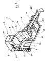
Figure 1 est une vue en perspective de l'installation selon l'invention.TheFigure 1 is a perspective view of the installation according to the invention. -
La
Figure 2 est une vue éclatée de l'installation de laFigure 1 .TheFigure 2 is an exploded view of the installation of theFigure 1 . -
La
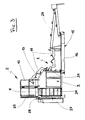
Figure 3 est une vue par le côté gauche de l'installation de laFigure 1 , étant ici précisé que l'avant de ladite installation est constitué par la structure qui est surplombée par la passerelle.TheFigure 3 is a view from the left side of the installation of theFigure 1 , being specified here that the front of said installation is constituted by the structure which is overhung by the bridge. -
La
Figure 4 est une vue de dessus de l'installation de laFigure 1 .TheFigure 4 is a top view of the installation of theFigure 1 . -
La
Figure 5 est une vue de l'installation de laFigure 1 prise par son avant.TheFigure 5 is a view of the installation of theFigure 1 taken by his front. -
La
Figure 6 représente schématiquement l'installation selon l'invention vue en perspective, et dans la structure en forme de berceau de laquelle il a été placé une benne en cours de lavage.TheFigure 6 schematically represents the plant according to the invention seen in perspective, and in the cradle-shaped structure of which it was placed a bucket during washing. -
La
Figure 7 représente schématiquement l'installation selon l'invention vue par le côté gauche, et dans la structure en forme de berceau de laquelle repose une benne en cours de lavage.TheFigure 7 schematically represents the installation according to the invention seen from the left side, and in the cradle-shaped structure of which rests a bucket during washing. -
La
Figure 8 est une vue en perspective d'un mode de réalisation préféré du diffuseur disposé dans le fond du deuxième bac de décantation et dont le rôle est d'injecter du gaz CO2 pour abaisser jusqu'à une valeur acceptable le pH des eaux de lavage contenues dans ledit deuxième bac de décantation.TheFigure 8 is a perspective view of a preferred embodiment of the diffuser disposed in the bottom of the second settling tank and whose role is to inject CO 2 gas to lower to an acceptable value the pH of the washing water contained in said second settling tank.
Dans toute la description qui va suivre, la structure repérée par 1 dans son ensemble, qui est disposée devant la passerelle 2 et qui forme un volume libre agencé pour recevoir en son centre et y maintenir la benne 6 à nettoyer, est accrochée sur au moins deux des trois éléments constitués par l'armoire technique 3, le deuxième bac de décantation 4 et le bac d'eau propre 5. Pour exemple, cet accrochage est réalisé au moyen de boulonnages tels que 30 et il est de préférence assuré sur l'armoire technique 3 et sur le deuxième bac de décantation 4.Throughout the following description, the structure marked by 1 as a whole, which is arranged in front of the
Il est clair toutefois que ce type d'attache peut être différent sans que l'invention s'en trouve modifiée, et pour exemple la structure 1 peut être directement fixée sur la passerelle 2 comme cela est décrit en détail dans le brevet européen n°
Identiquement à ce qui a été décrit dans ce brevet européen n°
Toujours identiquement à ce qui a été décrit dans le document précité, la passerelle 2 surplombe une structure métallique 1 qui est disposée devant elle et qui forme en son centre un volume libre 11 délimité et agencé par construction pour recevoir et y maintenir la benne 6 à nettoyer, de préférence dans une position où ladite benne est en position inclinée afin que son ouverture 12 par laquelle est introduit le béton soit tournée vers la passerelle 2.Still identically to what has been described in the aforementioned document, the
Le volume libre 11 de la structure 1 est délimité par différents moyens de la benne qui sont séparés les uns des autres, à savoir des moyens 13 disposés en partie haute de la structure, qui supportent et retiennent la benne, et des moyens 14 disposés en partie basse de la structure et qui, également, supportent, voire retiennent, la benne.The free volume 11 of the
Avantageusement, la structure 1, qui forme ainsi un berceau dans lequel la benne à nettoyer va pouvoir être logée, est prévue pour s'articuler relativement à la passerelle 2. Elle peut occuper soit une position de travail dans laquelle ses moyens de support et de retenue inférieurs reposent sur le sol, soit une position de rangement, ou de transport, représentée en pointillés à la
La structure 1 en forme de berceau surplombe un bac 15 de rétention et de décantation des eaux de lavage, ce bac 15 étant disposé au sol, à la verticale de la structure. De préférence, le bac 15 est équipé d'un filtre 16 à très grosses mailles, ou d'une tôle ajourée 16, ce filtre ou cette tôle 16 étant disposé transversalement à l'intérieur du bac. La fonction de ce bac est de procéder à une première séparation des résidus de béton éliminés de la benne par les eaux de lavage, les eaux les plus chargées, qui s'écoulent depuis la goulotte 17 de la benne, se déversant dans la partie avant du bac et les eaux les moins chargées, qui s'écoulent depuis le corps de la benne, se déversant dans la partie arrière du bac. C'est bien évidemment l'eau prise en surface en partie arrière du bac qui est réutilisée pour les futurs lavages, l'essentiel des résidus de béton restant bloqués en avant du filtre 16 pendant que le liquide passe à travers les mailles du filtre au fur et à mesure du pompage des eaux les moins chargées en partie arrière du bac 15, le liquide qui traverse le filtre ne pouvant ainsi qu'être chargé en particules relativement fines.The
En toute hypothèse, entre les opérations de pompage, il se produit une décantation des eaux souillées, tant dans la partie arrière que dans la partie avant du bac de rétention 15, les particules fines en suspension en partie arrière du bac et les particules lourdes en suspension en partie avant du bac se déposant par sédimentation au fond de celui-ci et pouvant dès lors en être retirées, les unes et les autres, à l'aide par exemple d'outils du genre raclettes, aussi fréquemment que cela sera nécessaire.In any case, between the pumping operations, there is a decantation of the dirty water, both in the part back only in the front part of the
A cette fin, le bac 15 pourra être avantageusement doté d'un platelage 15', de préférence amovible et déplaçable d'avant en arrière, sur lequel le compagnon se tenant debout sera à même de nettoyer le fond du bac. Ce platelage 15' permettra aussi au compagnon d'accéder plus facilement, en zones basse et avant, à toutes les parties à laver de la benne, tout en sécurisant la zone de lavage.To this end, the
L'armoire technique 3 est équipée d'un coffret d'alimentation électrique 18, d'une pompe de relevage 19, pour le pompage des eaux peu souillées en surface de la partie arrière du bac 15, pompe qui est reliée à un tuyau d'aspiration schématisé par sa prise 20, et d'une pompe équipée d'un pistolet de lavage sous pression des matériels de chantier schématisé par son support 21, ainsi qu'il est particulièrement visible aux
Entre la pompe de relevage 19 et le support 21 du pistolet de lavage, il est prévu une unité de traitement des eaux de lavage souillées, cette unité de traitement se composant essentiellement d'un deuxième bac de décantation 4 et d'un bac d'eau propre retraitée 5.Between the lifting
Conformément à l'invention, dans un souci de compacité de cet ensemble, le deuxième bac 4 repose sur le bac d'eau propre 5, ces deux bacs sont immédiatement adjacents à l'armoire technique 3, et l'ensemble ainsi constitué par les trois éléments 3, 4 et 5 précités est placé sous la passerelle 2.According to the invention, for the sake of compactness of this assembly, the
Dans une première variante de construction, l'ensemble est placé de sorte à ne pas déborder le piétement de la passerelle, tant sur les côtés latéraux 22 que sur le côté arrière 23 opposé à celui qui fait face à la structure 1.In a first variant of construction, the assembly is placed so as not to overflow the base of the bridge, both on the lateral sides 22 and on the
Dans une seconde variante de construction, illustrée sur les dessins d'accompagnement, les arêtes gauches de l'armoire technique 3 et les arêtes droites des bacs 4 et 5 sont renforcées par des profilés ou des cornières métalliques tels que 24, qui constituent des prolongements des poteaux d'angle 25 des rambardes 10.In a second construction variant, illustrated in the accompanying drawings, the left edges of the
Dans ces deux variantes, l'ensemble constitué des trois éléments 3, 4 et 5 n'émerge pas de la passerelle 2 et est protégé des chocs que pourraient occasionner des véhicules lors de leurs manoeuvres.In these two variants, the assembly consisting of the three
Afin de pouvoir disposer de bacs 4 et 5 de capacités plus importantes, on prévoit que l'ensemble précité déborde la passerelle 2 vers l'avant et s'encastre pour partie sous la structure 1, sans toutefois gêner le passage d'une benne à nettoyer lorsque le grutier vient placer cette dernière dans le volume libre 11 jusqu'à ce qu'elle repose sur les moyens de maintien 13 et 14. Par cette construction, l'armoire technique, puisqu'elle sera alors plus longue, pourra être réduite en largeur, ce qui augmentera d'autant plus la capacité de chacun des bacs 4 et 5.In order to be able to have
Avantageusement, la hauteur de l'armoire technique 3 sera sensiblement égale à la hauteur du bac inférieur d'eau propre 5 augmentée de la hauteur du bac supérieur de décantation 4 afin, le cas échéant, de constituer un support supplémentaire pour la plateforme 8. L'armoire technique 3 et le bac supérieur 4 auront, par construction, des faces avant, respectivement 3' et 4', inclinées vers le sol d'arrière en avant, et ce toujours dans un souci de gain de place puisqu'alors ces deux éléments pourront venir s'encastrer sous les moyens de maintien supérieurs 13.Advantageously, the height of the
Le bac d'eau propre 5 doit être une enceinte protégée de toute projection. C'est la raison pour laquelle il est hautement préférable de le placer sous le deuxième bac de décantation 4, ce dernier le protégeant constamment naturellement. En outre, cette construction permettra à l'eau traitée dans le bac 4 de s'écouler par simple gravité dans le bac 5, alors que dans le cas inverse il faudrait faire appel à une pompe supplémentaire.The
Le bac d'eau propre 5 comprend en outre : une prise d'eau, qui sera raccordée par un tuyau au support 21, un filtre disposé en amont de ce tuyau, un dispositif du type vanne manuelle, électro-vanne ou bouchon par exemple, pour la vidange dudit bac 5 et, avantageusement, un niveau d'eau et une trappe de visite pour permettre son nettoyage, ladite trappe étant située sur l'une des trois faces libres accessibles dudit bac 5, c'est-à-dire sur le côté droit 22 ou sur le côté arrière 23, ou mieux encore sur le côté avant 23' puisqu'alors les souillures mal dirigées au cours d'un tel nettoyage tomberont automatiquement dans le bac de rétention 15 au lieu de se répandre sur le sol.The
Le deuxième bac de décantation 4 est pour sa part équipé d'une tôle de séparation 26, représentée en pointillés à la
Le deuxième bac de décantation 4 comprend en outre un dispositif de type vanne manuelle ou électro-vanne par exemple, pour le transvasement des eaux traitées dans ledit bac 4. Ce dernier sera également éventuellement doté d'une trappe de visite pour permettre son nettoyage, ladite trappe étant située sur le côté droit 22 ou sur le côté arrière 23, ou mieux encore sur le côté avant 23', c'est-à-dire sur l'une de ses trois faces libres accessibles.The
L'installation selon l'invention permet ainsi un recyclage complet des eaux de lavage. Ces dernières sont récupérées dans le premier bac de rétention 15, où elles sont soumises à une première décantation. Elles sont ensuite transférées, pour celles qui sont les moins souillées, dans le deuxième bac de décantation 4 où elles sont alors soumises à une deuxième décantation, à une récupération par séparation des éventuels résidus d'huiles de décoffrage et à un traitement de leur pH. Les eaux ainsi retraitées sont ensuite transférées dans le bac d'eau propre 5, où elles sont stockées afin de pouvoir être utilisées pour un lavage futur, sauf à être rejetées dans les égouts en fin de chantier, lorsque tous les matériels ont été nettoyés pour une dernière fois.The installation according to the invention thus allows a complete recycling of washing water. These are recovered in the
Dans l'une et l'autre de ces deux hypothèses, l'installation selon l'invention assure un retraitement tel que la valeur du pH de l'eau traitée dans le deuxième bac de décantation 4 est située dans la plage admissible de 6,5 à 8,5 et conforme quoi qu'il en soit à la valeur imposée par les autorités locales compétentes. Ainsi, lorsqu'en fin de chantier les eaux traitées sont mises à l'égout, il est certain que cela se fera sans risque de pollution.In either of these two hypotheses, the plant according to the invention ensures a reprocessing such that the pH value of the water treated in the
A cette fin, avant chaque transvasement d'eau du deuxième bac de décantation 4 dans le bac d'eau propre 5, l'unité de traitement assure un traitement du pH. Cette opération s'effectue sans apport d'acide, à la différence donc des techniques antérieures.To this end, before each transfer of water from the
Conformément à l'invention, pour traiter le pH, l'unité de traitement de la présente installation comprend des moyens d'injection de gaz CO2 dans les eaux de lavage contenues dans le deuxième bac de décantation 4. Ces moyens d'injection se composent d'une bouteille 27 de gaz CO2 et d'un détendeur fixé sur ladite bouteille et relié par un tuyau souple à un diffuseur de CO2 disposé dans le fond du deuxième bac de décantation 4, de préférence au milieu de ce bac, centré par rapport à la tôle séparatrice 26. La bouteille 27 de gaz CO2 est supportée par un porte-bouteille 28 lui-même fixé à l'arrière des bacs 4 et 5.According to the invention, in order to treat the pH, the treatment unit of the present installation comprises means for injecting CO 2 gas into the washing water contained in the
Dans une forme préférée de réalisation, le diffuseur 31 représenté à la
A cette fin, la tôle support 32 pliée en U est placée sensiblement au centre du fond du deuxième bac de décantation 4 et le tuyau poreux 35 est enroulé en trois ou quatre boucles dans ladite tôle, ainsi qu'il est représenté à la
Le tuyau poreux fait environ trois à quatre mètres de longueur. Il peut s'agir d'un simple tuyau d'arrosage qui laisse librement fuir le gaz CO2 du tuyau vers le liquide à traiter. Le tuyau poreux 35 est raccordé en 36 au tuyau non poreux 37 qui l'alimente en gaz CO2 à partir de la bouteille 27. Une vanne est avantageusement disposée au niveau du raccord 36 entre les deux tuyaux 35 et 37.The porous pipe is about three to four meters long. It can be a simple garden hose that lets the CO 2 gas escape freely from the pipe to the liquid to be treated. The
Le traitement des eaux souillées par injection de gaz CO2 dans le deuxième bac de décantation 4 est de préférence réalisé de manière semi-automatique, par exemple en réglant le détendeur à un débit d'environ cinquante litres par minute pour des cycles de chacun environ trois minutes. Après chaque cycle d'injection de gaz, et après également qu'il a été vérifié à l'aide d'un papier pH ou d'un pHmètre que la valeur du pH des eaux traitées est bien située dans la plage 6,5-8,5, la bouteille de gaz CO2 est fermée par sécurité.The treatment of dirty water by CO 2 gas injection in the
Compte tenu des différents éléments qui ont été détaillés ci-dessus et qui composent l'installation selon l'invention, l'armoire technique 3 comprendra aussi avantageusement :
- un surpresseur équipé d'une lance de nettoyage dotée d'un tuyau de lavage,
- un flotteur permettant de couper l'alimentation électrique de la pompe dans le cas où le niveau de l'eau dans le
bac d'eau propre 5 serait trop bas, - une crépine de relevage des eaux souillées, disposée en partie arrière du premier bac de rétention et de décantation 15,
- un flotteur permettant de couper l'alimentation électrique de la pompe dans le cas où le niveau de l'eau dans le premier bac de rétention et de décantation 15 serait trop bas,
- un tuyau de refoulement,
- une minuterie pour limiter dans le temps l'utilisation des pompes afin d'éviter toute détérioration de celles-ci,
- un dispositif de protection de l'ensemble des composants de l'installation en cas de températures extérieures négatives.
- a booster equipped with a cleaning lance with a washing hose,
- a float for cutting off the power supply of the pump in the case where the level of the water in the
clean water tank 5 is too low, - a strainer for lifting dirty water disposed in the rear part of the first holding and settling
tank 15, - a float for cutting off the power supply of the pump in the case where the level of the water in the first holding and settling
tank 15 is too low, - a discharge pipe,
- a timer to limit the use of pumps in time to avoid any deterioration thereof,
- a device for protecting all the components of the installation in case of negative external temperatures.
Comme il va de soi, l'invention ne se limite pas aux seuls modes d'exécution préférentiels décrits ci-dessus.It goes without saying that the invention is not limited to the only preferred embodiments described above.
Elle embrasse au contraire toutes les variantes de réalisation telles que divulguées dans les revendications, et notamment l'apport d'une goulotte 29 qui prolonge le premier bac de décantation 15 et qui est apte à recevoir et à supporter tout éventuel tuyau d'écoulement du béton disposé sous le corps de la benne 6 en cours de nettoyage. Cette goulotte étant sensiblement inclinée de haut en bas vers l'avant, elle permettra l'écoulement et la récupération des eaux de lavage de l'intérieur de la benne dans le bac de rétention, tout en maintenant au sec le tuyau lors des phases de stockage de la benne sur l'installation afin de limiter sa dégradation. Au cas où le tuyau prolongeant le corps de la benne 6 serait trop long et s'étendrait au-delà du bord avant du premier bac 15, il est prévu de construire la goulotte 29 en deux segments superposés et d'inclinaisons inverses, ainsi que cela a été représenté aux
De même, il est possible de prévoir un dispositif de maintien hors gel de l'installation selon l'invention, afin d'éviter toute détérioration du matériel, si une telle installation est appelée à fonctionner en hiver et/ou dans des pays froids. Un tel dispositif comprendra alors des gaines chauffantes autour des pompes et autour de toutes les canalisations de circulation d'eau.Similarly, it is possible to provide a frost-free holding device of the installation according to the invention, in order to avoid any deterioration of the equipment, if such an installation is to operate in winter and / or in cold countries. Such a device will then include heating ducts around the pumps and around all water circulation pipes.
Claims (16)
Applications Claiming Priority (1)
| Application Number | Priority Date | Filing Date | Title |
|---|---|---|---|
| FR0900795A FR2942417B1 (en) | 2009-02-20 | 2009-02-20 | INSTALLATION FOR THE WASHING OF CONSTRUCTION AND TREATMENT EQUIPMENT, MONITORED WITH RECYCLING, WATER USED FOR SUCH WASHING |
Publications (2)
| Publication Number | Publication Date |
|---|---|
| EP2221434A1 true EP2221434A1 (en) | 2010-08-25 |
| EP2221434B1 EP2221434B1 (en) | 2011-02-23 |
Family
ID=41010886
Family Applications (1)
| Application Number | Title | Priority Date | Filing Date |
|---|---|---|---|
| EP10290088A Active EP2221434B1 (en) | 2009-02-20 | 2010-02-22 | Facility for washing plant machinery and for treating the water used for such washing process, followed by recycling same |
Country Status (6)
| Country | Link |
|---|---|
| EP (1) | EP2221434B1 (en) |
| AT (1) | ATE499495T1 (en) |
| DE (1) | DE602010000005D1 (en) |
| ES (1) | ES2361722T3 (en) |
| FR (1) | FR2942417B1 (en) |
| PT (1) | PT2221434E (en) |
Cited By (5)
| Publication number | Priority date | Publication date | Assignee | Title |
|---|---|---|---|---|
| WO2013124639A1 (en) * | 2012-02-21 | 2013-08-29 | Siltbuster Limited | Concrete washout unit and method |
| FR2990936A1 (en) * | 2012-07-13 | 2013-11-29 | Laurent Topelet | INSTALLATION FOR WASHING AND RECYCLING WATER CHARGED WITH GRAVES |
| FR3007755A1 (en) * | 2013-06-28 | 2015-01-02 | Secatol | RECYCLING STATION OF WASHING WATER OF CONSTRUCTION EQUIPMENT |
| FR3031973A1 (en) * | 2015-01-23 | 2016-07-29 | Vcf Tp Lyon | DEVICE FOR TREATING WASHING WATER FROM A CONCRETE WASTE CHUTE. |
| CN117583345A (en) * | 2024-01-19 | 2024-02-23 | 上海奔曜科技有限公司 | Vessel cleaning device, vessel cleaning module, liquid distribution platform and liquid distribution system |
Families Citing this family (1)
| Publication number | Priority date | Publication date | Assignee | Title |
|---|---|---|---|---|
| FR3028191A1 (en) | 2014-11-07 | 2016-05-13 | Secatol | WASHING TOWER FOR CONCRETE BEAMS, COMPRISING CENTERING SKINS FOR THE INCLINED FACES OF THESE BEATS |
Citations (4)
| Publication number | Priority date | Publication date | Assignee | Title |
|---|---|---|---|---|
| FR2728004A1 (en) * | 1994-12-13 | 1996-06-14 | Meunier Jean Francis | Washing platform for concrete mixer |
| EP1464775A1 (en) | 2003-03-31 | 2004-10-06 | Société d'Etude et Construction d'Application de la Tolerie "SECATOL" SA | Cleaning platform for concrete bucket |
| US20050145624A1 (en) * | 2003-12-30 | 2005-07-07 | Minegar Peter J. | Construction residue transport system |
| FR2913894A1 (en) * | 2007-03-19 | 2008-09-26 | Air Vibration Services Sarl | Settling tub for rinsing roadwork equipments, comprises a bottom and side walls with a volume intended to receive rinsing water containing residues of construction materials, and an intermediate wall for retaining the residues |
-
2009
- 2009-02-20 FR FR0900795A patent/FR2942417B1/en not_active Expired - Fee Related
-
2010
- 2010-02-22 AT AT10290088T patent/ATE499495T1/en not_active IP Right Cessation
- 2010-02-22 DE DE602010000005T patent/DE602010000005D1/en active Active
- 2010-02-22 EP EP10290088A patent/EP2221434B1/en active Active
- 2010-02-22 PT PT10290088T patent/PT2221434E/en unknown
- 2010-02-22 ES ES10290088T patent/ES2361722T3/en active Active
Patent Citations (4)
| Publication number | Priority date | Publication date | Assignee | Title |
|---|---|---|---|---|
| FR2728004A1 (en) * | 1994-12-13 | 1996-06-14 | Meunier Jean Francis | Washing platform for concrete mixer |
| EP1464775A1 (en) | 2003-03-31 | 2004-10-06 | Société d'Etude et Construction d'Application de la Tolerie "SECATOL" SA | Cleaning platform for concrete bucket |
| US20050145624A1 (en) * | 2003-12-30 | 2005-07-07 | Minegar Peter J. | Construction residue transport system |
| FR2913894A1 (en) * | 2007-03-19 | 2008-09-26 | Air Vibration Services Sarl | Settling tub for rinsing roadwork equipments, comprises a bottom and side walls with a volume intended to receive rinsing water containing residues of construction materials, and an intermediate wall for retaining the residues |
Cited By (7)
| Publication number | Priority date | Publication date | Assignee | Title |
|---|---|---|---|---|
| WO2013124639A1 (en) * | 2012-02-21 | 2013-08-29 | Siltbuster Limited | Concrete washout unit and method |
| FR2990936A1 (en) * | 2012-07-13 | 2013-11-29 | Laurent Topelet | INSTALLATION FOR WASHING AND RECYCLING WATER CHARGED WITH GRAVES |
| EP2684848A1 (en) * | 2012-07-13 | 2014-01-15 | Laurent Topelet | System for cleaning and for recycling of water on building sites |
| FR3007755A1 (en) * | 2013-06-28 | 2015-01-02 | Secatol | RECYCLING STATION OF WASHING WATER OF CONSTRUCTION EQUIPMENT |
| FR3031973A1 (en) * | 2015-01-23 | 2016-07-29 | Vcf Tp Lyon | DEVICE FOR TREATING WASHING WATER FROM A CONCRETE WASTE CHUTE. |
| CN117583345A (en) * | 2024-01-19 | 2024-02-23 | 上海奔曜科技有限公司 | Vessel cleaning device, vessel cleaning module, liquid distribution platform and liquid distribution system |
| CN117583345B (en) * | 2024-01-19 | 2024-04-26 | 上海奔曜科技有限公司 | Vessel cleaning device, vessel cleaning module, liquid distribution platform and liquid distribution system |
Also Published As
| Publication number | Publication date |
|---|---|
| FR2942417A1 (en) | 2010-08-27 |
| ES2361722T3 (en) | 2011-06-21 |
| DE602010000005D1 (en) | 2011-04-07 |
| ATE499495T1 (en) | 2011-03-15 |
| EP2221434B1 (en) | 2011-02-23 |
| FR2942417B1 (en) | 2011-02-11 |
| PT2221434E (en) | 2011-05-23 |
Similar Documents
| Publication | Publication Date | Title |
|---|---|---|
| EP2221434B1 (en) | Facility for washing plant machinery and for treating the water used for such washing process, followed by recycling same | |
| CA2314542A1 (en) | Mobile washing and wastewater recovery unit | |
| JPH11216435A (en) | Closed loop pressure washing system and method | |
| US9943982B2 (en) | Concrete mixing transport truck chute washout system | |
| EP2684848B1 (en) | System for cleaning and for recycling of water on building sites | |
| US9937636B2 (en) | Concrete mixing transport truck chute washout system | |
| JP5406404B1 (en) | Cleaning and sorting device | |
| FR3007755B1 (en) | RECYCLING STATION OF WASHING WATER OF CONSTRUCTION EQUIPMENT | |
| EP3529021A1 (en) | Compact device for recycling plastic waste | |
| FR2913895A1 (en) | DECANTING BOX FOR CONCRETE BENCH | |
| FR3094175A1 (en) | Washing device for washing the entire exterior body, the bottom and the blades of robot mowers | |
| FR2949107A1 (en) | DEVICE FOR RECEIVING A WASTE COLLECTION CONTAINER AT LEAST PARTIALLY BURIED | |
| FR2930962A1 (en) | Platform for cleaning construction site material e.g. concrete mix truck's trough, has footboard combined with removable drum for simultaneously forming cleaning fluid reservoir, material dipping container and cleaning residue settling tank | |
| EP3240757A1 (en) | Improved site device for recycling washing water | |
| EP3681646B1 (en) | Apparatus, system and method for cleaning a wheelbarrow | |
| EP0769248B1 (en) | Fish washing installation and fish-support for such an installation | |
| JP2006068635A (en) | Washing device | |
| FR2932465A1 (en) | Receiving platform device for e.g. washing lorry, at construction site, has platform and ramp formed into modules, where elements of device are placed above ground without requiring underground equipment installation | |
| FR3085951A1 (en) | PROCESS FOR RECYCLING THE WATER USED BY A SELF-CLEANER FOR CLEANING A ROAD | |
| JP2005342687A (en) | Pumped-up sand washing and transporting system in settling basin | |
| FR2810010A1 (en) | Boat hull cleaning installation having U shape structure with vertical elements holding liquid cleaning pipe with high pressure pump refill and fixing unit boat position holding | |
| FR2907111A1 (en) | DEVICE FOR RECYCLING WATER BY DYNAMIC SEPARATION OF SLUDGE, AND WATER WASHING INSTALLATION PROVIDED WITH SUCH A DEVICE | |
| FR2978685A1 (en) | Device for cleaning container for hydroponic culture for endives, has washing block including support structure, spraying units and separation units for separation of solid and liquid wastes, and processing unit for processing liquid waste | |
| FR2858286A1 (en) | Washing installation for e.g. truck, has washing tank comprising two vertical transversal walls with length not exceeding two and half meters, and spraying bars provided at interior of tank to wash vehicle lower side | |
| FR3080342A1 (en) | AREA FOR CLEANING VEHICLES |
Legal Events
| Date | Code | Title | Description |
|---|---|---|---|
| PUAI | Public reference made under article 153(3) epc to a published international application that has entered the european phase |
Free format text: ORIGINAL CODE: 0009012 |
|
| 17P | Request for examination filed |
Effective date: 20100301 |
|
| AK | Designated contracting states |
Kind code of ref document: A1 Designated state(s): AT BE BG CH CY CZ DE DK EE ES FI FR GB GR HR HU IE IS IT LI LT LU LV MC MK MT NL NO PL PT RO SE SI SK SM TR |
|
| AX | Request for extension of the european patent |
Extension state: AL BA RS |
|
| GRAP | Despatch of communication of intention to grant a patent |
Free format text: ORIGINAL CODE: EPIDOSNIGR1 |
|
| RIC1 | Information provided on ipc code assigned before grant |
Ipc: E04G 21/02 20060101AFI20101025BHEP |
|
| GRAS | Grant fee paid |
Free format text: ORIGINAL CODE: EPIDOSNIGR3 |
|
| GRAA | (expected) grant |
Free format text: ORIGINAL CODE: 0009210 |
|
| AK | Designated contracting states |
Kind code of ref document: B1 Designated state(s): AT BE BG CH CY CZ DE DK EE ES FI FR GB GR HR HU IE IS IT LI LT LU LV MC MK MT NL NO PL PT RO SE SI SK SM TR |
|
| REG | Reference to a national code |
Ref country code: GB Ref legal event code: FG4D Free format text: NOT ENGLISH |
|
| REG | Reference to a national code |
Ref country code: CH Ref legal event code: EP |
|
| REG | Reference to a national code |
Ref country code: IE Ref legal event code: FG4D Free format text: LANGUAGE OF EP DOCUMENT: FRENCH |
|
| REF | Corresponds to: |
Ref document number: 602010000005 Country of ref document: DE Date of ref document: 20110407 Kind code of ref document: P |
|
| REG | Reference to a national code |
Ref country code: DE Ref legal event code: R096 Ref document number: 602010000005 Country of ref document: DE Effective date: 20110407 |
|
| REG | Reference to a national code |
Ref country code: PT Ref legal event code: SC4A Free format text: AVAILABILITY OF NATIONAL TRANSLATION Effective date: 20110513 |
|
| REG | Reference to a national code |
Ref country code: CH Ref legal event code: NV Representative=s name: INTERPAT LAW AG |
|
| REG | Reference to a national code |
Ref country code: NL Ref legal event code: T3 |
|
| REG | Reference to a national code |
Ref country code: ES Ref legal event code: FG2A Ref document number: 2361722 Country of ref document: ES Kind code of ref document: T3 Effective date: 20110621 |
|
| LTIE | Lt: invalidation of european patent or patent extension |
Effective date: 20110223 |
|
| PG25 | Lapsed in a contracting state [announced via postgrant information from national office to epo] |
Ref country code: SE Free format text: LAPSE BECAUSE OF FAILURE TO SUBMIT A TRANSLATION OF THE DESCRIPTION OR TO PAY THE FEE WITHIN THE PRESCRIBED TIME-LIMIT Effective date: 20110223 Ref country code: GR Free format text: LAPSE BECAUSE OF FAILURE TO SUBMIT A TRANSLATION OF THE DESCRIPTION OR TO PAY THE FEE WITHIN THE PRESCRIBED TIME-LIMIT Effective date: 20110524 Ref country code: NO Free format text: LAPSE BECAUSE OF FAILURE TO SUBMIT A TRANSLATION OF THE DESCRIPTION OR TO PAY THE FEE WITHIN THE PRESCRIBED TIME-LIMIT Effective date: 20110523 Ref country code: LV Free format text: LAPSE BECAUSE OF FAILURE TO SUBMIT A TRANSLATION OF THE DESCRIPTION OR TO PAY THE FEE WITHIN THE PRESCRIBED TIME-LIMIT Effective date: 20110223 Ref country code: LT Free format text: LAPSE BECAUSE OF FAILURE TO SUBMIT A TRANSLATION OF THE DESCRIPTION OR TO PAY THE FEE WITHIN THE PRESCRIBED TIME-LIMIT Effective date: 20110223 |
|
| PG25 | Lapsed in a contracting state [announced via postgrant information from national office to epo] |
Ref country code: BG Free format text: LAPSE BECAUSE OF FAILURE TO SUBMIT A TRANSLATION OF THE DESCRIPTION OR TO PAY THE FEE WITHIN THE PRESCRIBED TIME-LIMIT Effective date: 20110523 Ref country code: SI Free format text: LAPSE BECAUSE OF FAILURE TO SUBMIT A TRANSLATION OF THE DESCRIPTION OR TO PAY THE FEE WITHIN THE PRESCRIBED TIME-LIMIT Effective date: 20110223 Ref country code: FI Free format text: LAPSE BECAUSE OF FAILURE TO SUBMIT A TRANSLATION OF THE DESCRIPTION OR TO PAY THE FEE WITHIN THE PRESCRIBED TIME-LIMIT Effective date: 20110223 Ref country code: AT Free format text: LAPSE BECAUSE OF FAILURE TO SUBMIT A TRANSLATION OF THE DESCRIPTION OR TO PAY THE FEE WITHIN THE PRESCRIBED TIME-LIMIT Effective date: 20110223 Ref country code: CY Free format text: LAPSE BECAUSE OF FAILURE TO SUBMIT A TRANSLATION OF THE DESCRIPTION OR TO PAY THE FEE WITHIN THE PRESCRIBED TIME-LIMIT Effective date: 20110223 |
|
| PG25 | Lapsed in a contracting state [announced via postgrant information from national office to epo] |
Ref country code: EE Free format text: LAPSE BECAUSE OF FAILURE TO SUBMIT A TRANSLATION OF THE DESCRIPTION OR TO PAY THE FEE WITHIN THE PRESCRIBED TIME-LIMIT Effective date: 20110223 Ref country code: DK Free format text: LAPSE BECAUSE OF FAILURE TO SUBMIT A TRANSLATION OF THE DESCRIPTION OR TO PAY THE FEE WITHIN THE PRESCRIBED TIME-LIMIT Effective date: 20110223 |
|
| PG25 | Lapsed in a contracting state [announced via postgrant information from national office to epo] |
Ref country code: SK Free format text: LAPSE BECAUSE OF FAILURE TO SUBMIT A TRANSLATION OF THE DESCRIPTION OR TO PAY THE FEE WITHIN THE PRESCRIBED TIME-LIMIT Effective date: 20110223 Ref country code: RO Free format text: LAPSE BECAUSE OF FAILURE TO SUBMIT A TRANSLATION OF THE DESCRIPTION OR TO PAY THE FEE WITHIN THE PRESCRIBED TIME-LIMIT Effective date: 20110223 Ref country code: CZ Free format text: LAPSE BECAUSE OF FAILURE TO SUBMIT A TRANSLATION OF THE DESCRIPTION OR TO PAY THE FEE WITHIN THE PRESCRIBED TIME-LIMIT Effective date: 20110223 |
|
| PLBE | No opposition filed within time limit |
Free format text: ORIGINAL CODE: 0009261 |
|
| STAA | Information on the status of an ep patent application or granted ep patent |
Free format text: STATUS: NO OPPOSITION FILED WITHIN TIME LIMIT |
|
| PG25 | Lapsed in a contracting state [announced via postgrant information from national office to epo] |
Ref country code: HR Free format text: LAPSE BECAUSE OF FAILURE TO SUBMIT A TRANSLATION OF THE DESCRIPTION OR TO PAY THE FEE WITHIN THE PRESCRIBED TIME-LIMIT Effective date: 20110907 |
|
| 26N | No opposition filed |
Effective date: 20111124 |
|
| PG25 | Lapsed in a contracting state [announced via postgrant information from national office to epo] |
Ref country code: PL Free format text: LAPSE BECAUSE OF FAILURE TO SUBMIT A TRANSLATION OF THE DESCRIPTION OR TO PAY THE FEE WITHIN THE PRESCRIBED TIME-LIMIT Effective date: 20110223 |
|
| REG | Reference to a national code |
Ref country code: DE Ref legal event code: R097 Ref document number: 602010000005 Country of ref document: DE Effective date: 20111124 |
|
| PG25 | Lapsed in a contracting state [announced via postgrant information from national office to epo] |
Ref country code: MK Free format text: LAPSE BECAUSE OF FAILURE TO SUBMIT A TRANSLATION OF THE DESCRIPTION OR TO PAY THE FEE WITHIN THE PRESCRIBED TIME-LIMIT Effective date: 20110223 |
|
| PG25 | Lapsed in a contracting state [announced via postgrant information from national office to epo] |
Ref country code: MT Free format text: LAPSE BECAUSE OF FAILURE TO SUBMIT A TRANSLATION OF THE DESCRIPTION OR TO PAY THE FEE WITHIN THE PRESCRIBED TIME-LIMIT Effective date: 20110223 |
|
| PG25 | Lapsed in a contracting state [announced via postgrant information from national office to epo] |
Ref country code: HR Free format text: LAPSE BECAUSE OF FAILURE TO SUBMIT A TRANSLATION OF THE DESCRIPTION OR TO PAY THE FEE WITHIN THE PRESCRIBED TIME-LIMIT Effective date: 20110223 |
|
| PG25 | Lapsed in a contracting state [announced via postgrant information from national office to epo] |
Ref country code: TR Free format text: LAPSE BECAUSE OF FAILURE TO SUBMIT A TRANSLATION OF THE DESCRIPTION OR TO PAY THE FEE WITHIN THE PRESCRIBED TIME-LIMIT Effective date: 20110223 |
|
| PG25 | Lapsed in a contracting state [announced via postgrant information from national office to epo] |
Ref country code: SM Free format text: LAPSE BECAUSE OF FAILURE TO SUBMIT A TRANSLATION OF THE DESCRIPTION OR TO PAY THE FEE WITHIN THE PRESCRIBED TIME-LIMIT Effective date: 20110223 |
|
| PG25 | Lapsed in a contracting state [announced via postgrant information from national office to epo] |
Ref country code: HU Free format text: LAPSE BECAUSE OF FAILURE TO SUBMIT A TRANSLATION OF THE DESCRIPTION OR TO PAY THE FEE WITHIN THE PRESCRIBED TIME-LIMIT Effective date: 20100222 |
|
| REG | Reference to a national code |
Ref country code: FR Ref legal event code: PLFP Year of fee payment: 7 |
|
| PG25 | Lapsed in a contracting state [announced via postgrant information from national office to epo] |
Ref country code: IS Free format text: LAPSE BECAUSE OF FAILURE TO SUBMIT A TRANSLATION OF THE DESCRIPTION OR TO PAY THE FEE WITHIN THE PRESCRIBED TIME-LIMIT Effective date: 20110223 |
|
| REG | Reference to a national code |
Ref country code: FR Ref legal event code: PLFP Year of fee payment: 8 |
|
| REG | Reference to a national code |
Ref country code: FR Ref legal event code: PLFP Year of fee payment: 9 |
|
| PGFP | Annual fee paid to national office [announced via postgrant information from national office to epo] |
Ref country code: IE Payment date: 20180221 Year of fee payment: 9 Ref country code: PT Payment date: 20180214 Year of fee payment: 9 |
|
| PGFP | Annual fee paid to national office [announced via postgrant information from national office to epo] |
Ref country code: ES Payment date: 20180328 Year of fee payment: 9 |
|
| PG25 | Lapsed in a contracting state [announced via postgrant information from national office to epo] |
Ref country code: PT Free format text: LAPSE BECAUSE OF NON-PAYMENT OF DUE FEES Effective date: 20190822 |
|
| REG | Reference to a national code |
Ref country code: IE Ref legal event code: MM4A |
|
| PG25 | Lapsed in a contracting state [announced via postgrant information from national office to epo] |
Ref country code: IE Free format text: LAPSE BECAUSE OF NON-PAYMENT OF DUE FEES Effective date: 20190222 |
|
| REG | Reference to a national code |
Ref country code: ES Ref legal event code: FD2A Effective date: 20200331 |
|
| PG25 | Lapsed in a contracting state [announced via postgrant information from national office to epo] |
Ref country code: ES Free format text: LAPSE BECAUSE OF NON-PAYMENT OF DUE FEES Effective date: 20190223 |
|
| P01 | Opt-out of the competence of the unified patent court (upc) registered |
Effective date: 20230606 |
|
| PGFP | Annual fee paid to national office [announced via postgrant information from national office to epo] |
Ref country code: LU Payment date: 20240220 Year of fee payment: 15 |
|
| PGFP | Annual fee paid to national office [announced via postgrant information from national office to epo] |
Ref country code: NL Payment date: 20240202 Year of fee payment: 15 |
|
| PGFP | Annual fee paid to national office [announced via postgrant information from national office to epo] |
Ref country code: MC Payment date: 20240226 Year of fee payment: 15 |
|
| PGFP | Annual fee paid to national office [announced via postgrant information from national office to epo] |
Ref country code: DE Payment date: 20240227 Year of fee payment: 15 Ref country code: GB Payment date: 20240201 Year of fee payment: 15 Ref country code: CH Payment date: 20240301 Year of fee payment: 15 |
|
| PGFP | Annual fee paid to national office [announced via postgrant information from national office to epo] |
Ref country code: IT Payment date: 20240221 Year of fee payment: 15 Ref country code: FR Payment date: 20240201 Year of fee payment: 15 Ref country code: BE Payment date: 20240219 Year of fee payment: 15 |