EP2220965A2 - Système de présentation doté de rails de profil de support - Google Patents
Système de présentation doté de rails de profil de support Download PDFInfo
- Publication number
- EP2220965A2 EP2220965A2 EP10001488A EP10001488A EP2220965A2 EP 2220965 A2 EP2220965 A2 EP 2220965A2 EP 10001488 A EP10001488 A EP 10001488A EP 10001488 A EP10001488 A EP 10001488A EP 2220965 A2 EP2220965 A2 EP 2220965A2
- Authority
- EP
- European Patent Office
- Prior art keywords
- line
- rail
- presentation system
- carrier
- contact
- Prior art date
- Legal status (The legal status is an assumption and is not a legal conclusion. Google has not performed a legal analysis and makes no representation as to the accuracy of the status listed.)
- Granted
Links
Images


Classifications
-
- A—HUMAN NECESSITIES
- A47—FURNITURE; DOMESTIC ARTICLES OR APPLIANCES; COFFEE MILLS; SPICE MILLS; SUCTION CLEANERS IN GENERAL
- A47B—TABLES; DESKS; OFFICE FURNITURE; CABINETS; DRAWERS; GENERAL DETAILS OF FURNITURE
- A47B97/00—Furniture or accessories for furniture, not provided for in other groups of this subclass
-
- A—HUMAN NECESSITIES
- A47—FURNITURE; DOMESTIC ARTICLES OR APPLIANCES; COFFEE MILLS; SPICE MILLS; SUCTION CLEANERS IN GENERAL
- A47F—SPECIAL FURNITURE, FITTINGS, OR ACCESSORIES FOR SHOPS, STOREHOUSES, BARS, RESTAURANTS OR THE LIKE; PAYING COUNTERS
- A47F11/00—Arrangements in shop windows, shop floors or show cases
- A47F11/06—Means for bringing about special optical effects
- A47F11/10—Arrangements of light sources
-
- A—HUMAN NECESSITIES
- A47—FURNITURE; DOMESTIC ARTICLES OR APPLIANCES; COFFEE MILLS; SPICE MILLS; SUCTION CLEANERS IN GENERAL
- A47F—SPECIAL FURNITURE, FITTINGS, OR ACCESSORIES FOR SHOPS, STOREHOUSES, BARS, RESTAURANTS OR THE LIKE; PAYING COUNTERS
- A47F5/00—Show stands, hangers, or shelves characterised by their constructional features
- A47F5/08—Show stands, hangers, or shelves characterised by their constructional features secured to the wall, ceiling, or the like; Wall-bracket display devices
- A47F5/0807—Display panels, grids or rods used for suspending merchandise or cards supporting articles; Movable brackets therefor
- A47F5/0846—Display panels or rails with elongated channels; Sliders, brackets, shelves, or the like, slidably attached therein
-
- A—HUMAN NECESSITIES
- A47—FURNITURE; DOMESTIC ARTICLES OR APPLIANCES; COFFEE MILLS; SPICE MILLS; SUCTION CLEANERS IN GENERAL
- A47B—TABLES; DESKS; OFFICE FURNITURE; CABINETS; DRAWERS; GENERAL DETAILS OF FURNITURE
- A47B2220/00—General furniture construction, e.g. fittings
- A47B2220/0075—Lighting
- A47B2220/0077—Lighting for furniture, e.g. cupboards and racks
-
- F—MECHANICAL ENGINEERING; LIGHTING; HEATING; WEAPONS; BLASTING
- F21—LIGHTING
- F21V—FUNCTIONAL FEATURES OR DETAILS OF LIGHTING DEVICES OR SYSTEMS THEREOF; STRUCTURAL COMBINATIONS OF LIGHTING DEVICES WITH OTHER ARTICLES, NOT OTHERWISE PROVIDED FOR
- F21V21/00—Supporting, suspending, or attaching arrangements for lighting devices; Hand grips
- F21V21/34—Supporting elements displaceable along a guiding element
- F21V21/35—Supporting elements displaceable along a guiding element with direct electrical contact between the supporting element and electric conductors running along the guiding element
-
- F—MECHANICAL ENGINEERING; LIGHTING; HEATING; WEAPONS; BLASTING
- F21—LIGHTING
- F21W—INDEXING SCHEME ASSOCIATED WITH SUBCLASSES F21K, F21L, F21S and F21V, RELATING TO USES OR APPLICATIONS OF LIGHTING DEVICES OR SYSTEMS
- F21W2131/00—Use or application of lighting devices or systems not provided for in codes F21W2102/00-F21W2121/00
- F21W2131/40—Lighting for industrial, commercial, recreational or military use
- F21W2131/405—Lighting for industrial, commercial, recreational or military use for shop-windows or displays
-
- F—MECHANICAL ENGINEERING; LIGHTING; HEATING; WEAPONS; BLASTING
- F21—LIGHTING
- F21Y—INDEXING SCHEME ASSOCIATED WITH SUBCLASSES F21K, F21L, F21S and F21V, RELATING TO THE FORM OR THE KIND OF THE LIGHT SOURCES OR OF THE COLOUR OF THE LIGHT EMITTED
- F21Y2115/00—Light-generating elements of semiconductor light sources
- F21Y2115/10—Light-emitting diodes [LED]
-
- H—ELECTRICITY
- H01—ELECTRIC ELEMENTS
- H01R—ELECTRICALLY-CONDUCTIVE CONNECTIONS; STRUCTURAL ASSOCIATIONS OF A PLURALITY OF MUTUALLY-INSULATED ELECTRICAL CONNECTING ELEMENTS; COUPLING DEVICES; CURRENT COLLECTORS
- H01R25/00—Coupling parts adapted for simultaneous co-operation with two or more identical counterparts, e.g. for distributing energy to two or more circuits
- H01R25/14—Rails or bus-bars constructed so that the counterparts can be connected thereto at any point along their length
Definitions
- the invention relates to a presentation system for presenting goods, a support rail, in particular for use in presentation systems, and a male element therefor.
- WO 2007/020470 A1 From the WO 2007/020470 A1 is a presentation system known, as it is commonly used at trade fairs or in shops. It comprises at least two preferably vertically arranged carriers, to which a plurality of presentation elements in the form of shelves are attached. On the shelves network devices, for example. In the form of display elements, can be arranged. For this purpose, a power supply is integrated into the system. In addition, the presentation system has a data line for supplying data from a central server to the display elements. For this purpose, a combined power and data line is used, which is arranged on the carriers or shelves or integrated therein.
- Presentation elements can only be positioned one above the other in discrete grid positions and at discrete locations next to each other. In the latter case, several such vertical beams must be installed.
- presentation systems are needed that enable quick and easy insertion and transfer of the presentation elements, which can be changed to any position.
- room divider systems eg US 6,446,396 B1
- the carrier and fastened thereto elements wherein in the carrier and the elements, a power supply is integrated.
- furniture eg US 6,231,205 B1
- systems with integrated power supply are known.
- carrier profile rails preferably made of aluminum, are used, which have a receiving slot which extends through in the longitudinal direction. In this receiving slot presentation elements can be inserted at any point.
- the object of the invention is to provide a presentation system, which is simple and modular and makes it possible to integrate electrical and possibly network-enabled terminals. It is a further object of the invention to provide a simply constructed, flexible to use and suitable for receiving electrical or electronic devices support rail, in particular for use in such presentation systems, and to create a plug-in element for this purpose.
- the presentation system has at least one support rail with a receiving slot for one or more male members, and an electrical or electronic device which is connected to the male member or connectable. Furthermore, an integrated into the presentation system, multi-part power and / or data line connection for the electronic device is provided, wherein a first part of the line connection to the carrier rail and a second part is arranged on the male member.
- an adapter module for releasably conductive connection of arranged on the support rail first line part with the insertion element arranged on the second line part it is possible to automatically connect the male elements in the mechanical mounting to the support rail conductively connected to the line system of the presentation system and in this integrate. No complicated wiring work and expertise is required to make the connection and mis-installation is prevented.
- the male elements can be hung easily and variably at different points in the professional rail be made simultaneously with the electrical connection.
- the conductive connection of the first line part arranged on the carrier profile rail can be easily realized with a first line part arranged on a further carrier profile rail or with a line part arranged fixedly in space.
- the line connection has both a high-voltage and a low-voltage and a data line.
- This allows the greatest possible design freedom in the construction of presentation walls using electrical equipment.
- individual ones of these lines can be omitted.
- the low voltage and data connections can also be made in a single line, also e.g. a bus line, be integrated.
- Under a line or line arrangement is here a set of conductor elements, such as cables, conductors or the like., Understood to form a circuit. Each line may have two or more conductor elements.
- the electronic device can be arranged on the presentation system such that at the same time all the necessary conductive connections between the electronic device and the line connection can be produced on the presentation system by arranging.
- the adapter module can already be attached to the male element, connected to the device via the second line section, and configured such that it automatically achieves a mechanical security in it when inserted into the receiving slot of the carrier profile rail and at the same time establishes a conductive connection between the first and second line sections , This allows time-saving installation and at the same time reliably prevents errors.
- the male elements have a uniform, "normalized” receptacle for the adapter module.
- the adapter module is preferably designed so that it is equipped for maximum equipment of the presentation system with power and data lines. That is, for each conductor element of each possible first line part on the carrier rail is a corresponding connection or contact point for making a conductive connection with the first line part to the support rail and a corresponding number of second connection or contact points for making a conductive connection with the second conduit part provided on a male element on the adapter module. Furthermore, a plurality of line connections for connecting each of all corresponding first and second contact points are provided on or in the adapter module.
- the actual contacting then takes place via elastic or elastically prestressed contact elements which are provided on or in the contact points.
- contact elements which are provided on or in the contact points.
- it can be determined by arranging or omitting contact elements, whether the associated male member is connected to a high-voltage, a low-voltage and / or a data line.
- the adapter module is thus flexibly configurable.
- a corresponding system with contact points and elastic or elastically prestressed contact elements can advantageously also be provided for a second adapter part for the conductive connection of two carrier profile rails or for the conductive connection of a carrier profile rail with a spatially fixed connection.
- a carrier rail is provided, which is particularly but not exclusively suitable for use in the above-described presentation systems according to claim 1.
- the carrier rail according to the invention has a base plate and a first and a second leg, wherein the legs, starting from the base plate extending away from the distance away from each other and define between each other a receiving slot for a male element, which is accessible via a base plate opposite the inlet opening ,
- at least one extending in the longitudinal direction over the support rail rail arrangement is arranged on the support rail, preferably in the receiving slot.
- the carrier rail can also be equipped with two or more line arrangements.
- lines are provided for both high-voltage and low-voltage power supply as well as for data communication.
- these are preferably arranged distributed on opposite legs. This makes the electrical insulation easier. Short circuits between different line arrangements can be largely avoided.
- the contact with associated adapter modules and adapter parts is facilitated.
- the height of the entrance opening may be smaller than the thickness of a hand of an adult Average person or even a child. It may be less than 20 mm, preferably less than 10 mm, for example, about 7 mm. Also, the depth of the receiving slot may be sufficiently large to reduce the risk of accidental contact of the supply lines.
- the lines provided on different legs are preferably arranged offset from each other for better short-circuit protection in the depth direction of the receiving slot.
- Provided in the receiving slot on the legs support and support surfaces for the male, in particular the adapter module, preferably further project into the receiving slot than the conductor elements of the lines. This preferably also applies to the insulating means in which the conductor elements are embedded.
- the protective measures according to the invention can be provided individually or in combination with one another.
- the mechanical structure essentially corresponds to the structure of the carrier profile rails according to the prior art ( DE 103 06 002 A1 )
- the use of the carrier rails according to the invention is compatible with such conventional presentation system.
- these can essentially only be mounted in a horizontal orientation.
- a fixation of the male elements in the receiving slot of the support rail would not be possible.
- a plurality of insertion openings can be provided in the base plate of the support rail corresponding to the receiving slot in a defined pitch, can be mounted in which male with corresponding hook.
- the carrier rail according to the invention is flexible, can also be used in a vertical arrangement.
- this flexible system allows electronic devices to be easily and cost effectively integrated into a presentation system.
- a data connection can be realized in parallel become.
- the data connection but also the power supply, can also be combined with wireless transmission paths (eg WLAN or similar).
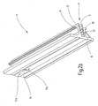
- a rear wall or any substructure 2 is covered with a total of 3 designated front wall.
- the front wall 3 is composed of a plurality of front wall elements 3a-3h.
- the front wall elements 3a-3h are held by carrier profile rails 4, which are mounted in the embodiment substantially in a horizontal position at a distance from each other on the rear wall 2.
- the carrier profile rails 4 are flush with the front wall elements 3a-3h, so that only horizontal receiving slots 5 between the front wall elements 3a-3h are released. In these receiving slots 5 more, generally designated 7 male members are mounted.
- the carrier profile rails 4 together with the male elements 7 form a carrier arrangement 8.
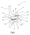
- the associated carrier rail 4 as shown in more detail in Fig. 2a-2c is shown, has a base plate 6 and an upper leg 9 and a lower leg 10, which are supported by the base plate 6 extend substantially perpendicular away.
- the support rail 4 is, for example, integrally formed and produced by means of the extrusion of aluminum.
- the base plate 6 is arranged with its rear side for mounting on a wall or on a substructure or supporting structure (not shown). Between the two legs 9, 10 of the receiving slot 5 is formed, which is accessible via an inlet opening 11 in front.
- the inlet opening 11 is provided on the front side 100 of the carrier profile rail 4 and formed by two substantially planar, parallel to each other and in use preferably horizontally extending inner surfaces 101, 102 of the legs 9, 10, which limit the receiving slot 5.
- the distance between the inner surfaces 101 and 102 is preferably less than 20 mm. It can even be less than 10 mm.
- the surface 101 of the upper leg is in the depth direction of the receiving slot 5 to the base plate 6 via a stepped transition region 103 in a projecting surface area 104, which is connected to the base plate 6 and forms a support surface.
- the lower inner surface 102 forms the support surface of the lower leg 10 and passes via a step 106 in a recessed surface area 107, which is located in the vicinity of the base plate 6.
- the receiving slot 5 thus has a slightly curved, (in the illustrated horizontal insertion position according to Fig. 2c ) to the rear and bottom sloping cross-sectional shape.
- the carrier rail 4 advantageously has an integrated line arrangement for power supply and data communication.
- a low-voltage line 12 (hereinafter NV line) is arranged on the upper leg 9, which has two conductor tracks or elements 12a and 12b and facing the receiving slot 5.
- this NV line 12 is a strip or ribbon-like line with a small cross-section, which is provided with an adhesive strip, which can be glued directly to the upper leg 9.
- the NV line 12 is preferably used simultaneously as a data line.
- voltages are referred to less than about 50 volts.
- it is a 6V, 12V or 24V voltage of conventional halogen or LED systems.
- the two conductor elements 12a, 12b extend in the receiving slot 5 parallel to each other along the rail 4, wherein the inlet opening 11 adjacent conductor element 12b is disposed slightly higher than the conductor element 12a further inside the receiving slot 5.
- the conductors 12a, 12b are electrically insulated from the upper leg 9 and from each other by an insulating means 120, which preferably extends beyond the exposed plane of the conductors 12a, 12b further into the slot 5 and thus provides contact protection.
- a high-voltage line 13 (hereinafter HV line) is arranged, which has three conductor tracks or elements 13a to 13c and also faces the receiving slot.
- HV line high-voltage line
- the three conductors 13a to 13c of the lower leg 10 and from each other by an insulating means 130 are electrically insulated, which projects beyond the slot 5 facing exposed conductor surfaces.
- the conductor 13a which is arranged at the lowest point in the interior is preferably the current-carrying conductor, also referred to as phase conductor, while the conductors 13b or 13c then form, for example, the neutral or protective conductor.
- HV lines 13 are available in the form of strip or ribbon-like lines with a small, flat cross-section, which can be glued directly onto the lower leg 10 via an adhesive tape.
- voltages of more than approximately 80 volts are referred to as high voltage.
- this is a conventional 120V or 240V AC power supply.
- the NV line 12 and the HV line 13 form a total of a first line section 22 of the voltage and data line connection.
- the carrier rail 4 further has in the base plate 6, corresponding to the receiving slot 5, a recess 14 and two associated mounting holes 15a, 15b.
- Through the recess 14 can preferably be a contacting of the first line section 22 to the support rail 4 with a fixed space line or with another Carrier rail done.
- this is a below in connection with Fig. 8 used closer illustrated adapter part, which is inserted into the receiving slot 5 and screwed using the mounting holes 15 on the base plate, clipped or otherwise secured.
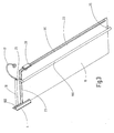
- FIG. 3 An application of such a carrier rail 4 in a presentation system 1 shows a partial view Fig. 3 , wherein only a very short section of the carrier rail 4 is shown.
- this support rail 4 two male elements 7, namely a lamp arm 16 with an LED lamp 17 and a glass bottom 18 with a hanging rod 190, a LED light bar 191 and a display 20, inserted.
- the LED lamp 17, the LED light bar 191 and the display 20 are referred to below as electronic or electrical devices.
- the second line section 23 extends here in the form of, for example, two line elements 23a along a short edge of the glass bottom 18 and further than Section 23b along a long edge on the front of the glass bottom. He could, if necessary, continue on the other short edge of the glass bottom 18.
- the lines on the glass bottom 18 could also be embedded within it or, for example, covered by a foil and only partially exposed at desired contacting points.
- the second line section 23 is by means of a in Fig. 3 and Fig. 4 not shown adapter module 35, which is described in detail below, connected to the NV line 12 of the first line section 22.
- a receptacle 24 for the adapter module 35 is arranged for this purpose.
- the receptacle 24 is in the glass bottom 18 in the form of a plan view formed in the substantially rectangular section, in which the adapter module can be used.
- the hanging rod 190 makes it possible to hang goods on it. It is attached by means of two holders 25 on the glass bottom 18 each at the end faces. Instead of or in addition to the suspension rod 190 there could also be an electrical or electronic device attached.
- the optional LED light bar 191 is attached to the underside of the glass bottom 18. This preferably extends in a parallel arrangement between the line section 23b and the long edge on the front side of the glass bottom 18 almost over this entire edge.
- the LED light bar 191 has a plurality of LED elements not shown here in detail and is electrically connected to the second line section 23.
- the display 20 is also attached, which is also connected to the second line section 23.
- FIG. 5 shown display 20 has a housing 26 which, with the aid of a two-piece locking unit 29, 33 can be fastened to the glass bottom 18.
- a display surface 27 is provided at the front of the housing 26 .
- Controls for controlling the display 20 may also be provided but are not shown.
- an upper part 29 and a lower part 33 of the latching unit are arranged in the form of two projecting arms. Together with a recess 28 formed therebetween, the two parts 29, 33 of the detent unit form a receptacle for the glass bottom 18.
- the two parts 29, 33 of the detent unit cooperate by receiving the glass bottom 18 between each other and light pinch.
- At least one arm, in this case the lower part 33 can be made somewhat elastic for this purpose.
- the conductive contact takes place here alone through the lower part 33.
- two conductor tracks 31 and two corresponding resilient connecting pieces 32 are arranged on the glass bottom 18 facing surface of the lower part 33.
- the two connecting pieces 32 are spatially arranged so that they produce a conductive connection between the two conductor tracks 31 on the display 20 and the second line section 23 on the glass bottom 18 in the mounted state.
- the lower part 33 of the latching unit has a bridge region 30 protruding from the glass bottom 18 in the middle region. In this area, the LED light bar 191 or a further part of the second line section 23 for supplying the LED light bar 191 can be laid on the glass bottom 18. In this case, a contact of the two conductor tracks 31 with the further line part or the LED light bar 191 is avoided by the bridge part 30.
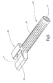
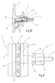
- Fig. 6 shows the lamp arm 16 according to Fig. 3 in detail.
- This lamp arm 16 is made of an electrically non-conductive material, for example. Plastic. It also has a receptacle 24 for an adapter module 35.
- this receptacle 24 on the lamp arm 16 preferably corresponds to the receptacle 24 on the glass bottom 18, so that an externally uniform adapter module 35 can be used for all plug-in elements 7.
- the receptacle 24 is arranged as a substantially rectangular recess in a plug-in region 160 of the lamp arm 16, which is inserted during assembly in the receiving slot 5 of the support rail 4.
- the insertion region 160 is substantially parallelepiped-shaped and has a height adapted to the size of the receiving slot 5.
- the insertion region 160 merges into a tubular support arm 161, which in use may also be coated with a metal sleeve, for example.
- the support arm 161 has a through opening in the interior, which at the free end of the lamp arm 16 in an insertion opening 34 for receiving the actual LED light opens.
- the conductive connection between the adapter module 35 and the LED lamp can be made via a cable positioned in the passage opening 34 or a connection line similar to the lines 12, 13.
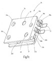
- adapter module 35 preferably has a housing with an upper part 36 and a lower part 37 and has an overall cuboid shape that fits into the receptacle 24 to the male elements 7.
- the adapter module 35 is snapped or clipped into the receptacle 24.
- the adapter module 35 on two opposite side surfaces locking lugs 350 which einfinden in corresponding latching openings 351 of the receptacle 24 of the lamp arm 16 and the glass bottom 18.
- the adapter module 35 can also be screwed to the male member 7, glued or connected permanently or detachably in any other way.
- connection or contact points 38a, 38b are arranged on the male member 7 facing end face 352 of the adapter module 35 on the upper housing part 36.
- three further connection or contact points 39a-c are arranged on the same front side of the lower part 37.
- a plurality of passage openings are arranged in the upper side 353 of the upper housing part 36, to which contact openings 40 and bores 354 belong, through which threaded bolts for securing the upper housing part 36 to the lower part 37 are received.
- conductive connections between the contact openings 40 and the associated NV contact points 38 are provided in the adapter module 35 further not shown conductive connections between the contact openings 40 and the associated NV contact points 38 are provided.
- Corresponding contact openings 40 in particular three contact openings 40, are also arranged in the underside 356 of the housing lower part 37. Furthermore, corresponding conductive connections are additionally provided between the contact openings 40 on the underside 356 and the HV contact points 39.
- elastic contact elements 41 which are preferably formed here by spring-loaded pressure balls.
- the pressure balls 41 sit in each selected contact openings 40 and are biased by not shown here spring elements against the edge of the contact openings 40 to the outside such that they slightly protrude beyond the respective flat top 353 and bottom 356.
- spring-loaded pressure balls 41 other resilient contacts, such as e.g. Contact lugs or tongues, be provided.
- Fig. 7a Us 7b are on the upper part 36 of the adapter module 35, two elastic contact elements 41 installed in corresponding contact openings 40.
- the position of these two contact openings 40 corresponds to the position of the NV conductor 12a, 12b of the first line section 22 on the support rail 4.
- the three contact openings 40 on the lower housing part 37 are then usually not equipped with an elastic contact element 41 and thus have no conductive contact with the first line section 22.
- Fig. 7a Us 7b are on the upper part 36 of the adapter module 35, two elastic contact elements 41 installed in corresponding contact openings 40.
- the position of these two contact openings 40 corresponds to the position of the NV conductor 12a, 12b of the first line section 22 on the support rail 4.
- contact elements 41 may be provided on the underside 356 to provide an HV connection in addition to or instead of the NV connection.
- the contact openings 40 on the underside 356 are created at positions that correspond in use to the positions of the conductor elements 13a-13c.
- two tabs 21 are plugged into the two HV pads 39a and 39b.
- a second line section 23 can then be connected during assembly with these two contact plugs 21 and thus connected to a line network.
- connection between the adapter module 35 and the support rail 4 is preferably carried out via spring-loaded pressure balls 41. These are pressed when inserting the male members 7 against the spring force in the associated contact opening 41 and then provide the conductive contact forth, they safely maintain.
- the maximum number of contact openings 41 is always present. However, the number and position of the pressure balls 41 is selected depending on the desired function.
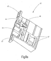
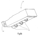
- a corresponding adapter part 42 as in the embodiment according to Fig. 8 can be used to connect the first line sections 22 of two carrier profile rails 4 or to connect the first line section 22 of a carrier rail 4 with a spatially fixed connection.
- the adapter part 42 corresponds functionally to the adapter module 35, wherein on the upper side of the adapter part 42 (see Fig. 8a ) two elastic NV-contact elements 46 and on the underside of the adapter part 42 (see Fig. 8b ) three elastic HV contact elements 47 are provided.
- On the back of the adapter part 42 two mounting holes 43 are arranged, by means of which the adapter part 42 can be fixed after insertion into the insertion opening 11 on the support rail.
- NV clutch 44 and HV clutch 45 are also arranged on the back of the adapter part 42.
- NV clutch 44 and HV clutch 45 are also arranged in these couplings 44, 45 .
- conductive connections (not shown) between the couplings 44, 45 and the associated elastic contact elements 47 and 46 are provided.
- cover 48 are provided, which is inserted after completion of the assembly on the open end face of a support rail 4.
- locking lugs 49a-d may be provided on the cover 48, which correspond to the corresponding profile of the support rail.
- the cover member 48 may be made of a suitable insulating material (eg, PVC).
- a flexible presentation system 1 is provided by the present invention.
- the choice of a suitable support rail 4 is the first step. In this case, preferably in Fig. 2 illustrated carrier rail 4 are used. However, other embodiments may be used.
- the desired type of cabling with NV, HV and / or data lines and the position of the individual line sections is provided.
- an NV line 12 with two conductors and a HV line with three conductors can be arranged on opposite sides of an insertion opening 11.
- several lines 12 or 13 can be arranged on only one side of the insertion opening 11. But it is also possible to provide a plurality of parallel insertion openings 11, in which case the lines 12, 13 can be divided into the different insertion openings.
- the carrier rail could also for a DC connection and / or a three-phase connection to be established.
- an adapter part is then designed so that it interacts mechanically with the insertion opening 11 of the carrier profile rail 4.
- the number and positions of the elastic contact elements 46, 47 are matched to the number and positions of the conductor elements of the lines 12, 13.
- the number and the position of the contact openings 40 and the contact points 38, 39 on the adapter module 35 are adapted to the number and position of the conductor elements 12a, 12b or 13a, 13b, 13c.
- any plug-in elements 7 can be designed that are mechanically compatible with the support rail. If such a plug-in element 7 is to be provided with a voltage and / or data line, it is preferable to provide a corresponding receptacle 24 on the plug-in element 7 and to provide the plug-in element 7 with a corresponding second line section 23.
- This second line section 23 begins in the region of the receptacle 24 in order to establish a connection with the adapter module 35.
- the connection between the second line section 23 and the tabs or connectors 21 of the adapter module 35 can be done by settlelastetes concern, plug-in connections, soldering or the like.
- the second conduit section 23 also extends below, on, in or on the insertion part 7 into a region in which an electronic device 17, 19, 20 is to be arranged.
- the electronic device 17, 19, 20 in turn can then be firmly connected to the plug-in part 7 or via a plug connection or the like releasably connected to the plug-in part 7.
- the appropriate connection of the electronic device 17, 19, 20 with the specific one of the plurality of first line sections 22 present is ensured via a suitably configured adapter module 35.
- the elastic contact elements 40 are placed on the adapter module 35 such that only a connection with the desired conductor elements of the first line section 22 is produced. That is, when using different electronic devices (eg LED lamp with NV supply, lamp with HV supply, display with NV and data supply) differently configured adapter modules are used, each having an identical outer shape, but have different contacts , As long as each male element 7 is equipped with the appropriate adapter module 35, care must be taken in the construction of the presentation system is no longer on a correct wiring. Rather, the correct conductive connection is automatically made when inserting the male element 7 with inserted adapter module.
- different electronic devices eg LED lamp with NV supply, lamp with HV supply, display with NV and data supply
- insertion element 7 is inserted at the desired position in a slightly inclined position through the insertion opening 11 into the receiving slot 5.
- the recessed, embedded in their environment arrangement of the conductor elements 12a, 12b, 13a, 13b, 13c, their position as well as the position and configuration of the contact elements 41 in the form of spring-loaded pressure balls help to effectively prevent short circuits when inserting the adapter module 35.
- the adapter module 35 is fully inserted, it is slightly pivoted down so that it comes to rest with its bottom 356 on the lower support surface 102, while it is supported with its top 353 against the upper support surface 104.
- the adapter module 35 can on its underside 356 a Have protrusion that prevents in interaction with the step 106 in the receiving slot 5 that the male member 7 from the slot 5 accidentally falls out or is pulled out.
- This state is shown in the schematic representation Fig. 10 illustrates in the case that a provided with an adapter module 35 male member 7 is connected to the HV power supply.
- the HV circuit via the pressure balls 41, provided in the adapter module 35 conductor means 49, connecting means 51 between the adapter module 35 and the male member 7, for example.
- a Lampenarm 16 the head of the second line section 23 and not shown here electronic device closed.
- the spring force for the contact elements 41 is selected such that the pressure balls 41 are optionally pressed when inserting the plug-in elements 7 in the contact openings 40 to support the insertion, but in the inserted state a secure and permanent contact with the conductor elements 12, 13 is ensured , Both high short-circuit and high contact safety can be achieved.
- Essential advantages of the invention include the fact that when inserting the male member 7 via the adapter module 35 automatically the correct connection is made, so that mounting errors avoided and no specialists are required for the installation. At the same time, the adapter modules can be produced in large quantities and thus low.
- the combination of the carrier rail 4 according to the invention and an insert element 7 equipped with the adapter module 35 according to the invention ensures high security. Presentation walls according to the invention can be constructed easily and quickly. The male members 7 can be very variable, easy and quickly reposition.
- carrier profile rails can be easily combined with the carrier profile rails 4 according to the invention with the first line section 22, so that an extension of existing presentation system 1 is easily possible.
- the carrier profile rails can be equipped with only one NV line or one HV line as needed.
- adapter parts 42 offer the advantage that the presentation system 1 can be connected very flexibly to the existing, fixed-space connections.
- additional sockets can be inserted as plug-in elements 7 at any point in the support rail 4.
- carrier profile rails 4 can be provided with a fixed integrated adapter part 42.
- the adapter part 42 can also be partially embodied in one piece with the carrier profile rail 4.
- the support rail 4 according to the invention and the insertion element 7 according to the invention, in particular the lamp or other support arm 16, can also be modified to be used in a vertical arrangement and moreover to ensure compatibility with known slot support systems.
- this can in the base plate 6 in the region of the insertion opening 11, this opposite corresponding Slots 52 are provided in a desired pattern.
- suitable male members 7 are provided with corresponding hooks 53, which are additionally hooked into the slots 51 during insertion into the insertion opening 11 in order to secure the male member 7 therein.
- this embodiment can also be used without an integrated power and data supply and it has the advantage over conventional presentation systems that it allows both a horizontal and a vertical deployment position of the support rail.
- the carrier rail can not be used only for presentation systems 1. Rather, this can also take over the function of a cable channel.
- Such cable ducts can be used in offices, in living rooms or shops, in partitions or in furniture systems.
- an additional cover can be provided, which is placed on the support rail 4 and thereby realized the desired appearance of a cable channel.
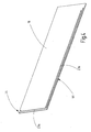
- Fig. 12 shows a modified embodiment of a presentation system 1 according to the invention
- the presentation wall discrete insertion openings 11 has.
- the carrier profile rail 4 is modified such that it has along its longitudinal extension at a distance from each other a number of incisions 54 which are configured as recesses in the front side 100 of the carrier profile rail 4. More specifically, here are targeted areas of the legs 9, 10, which connect directly to the front side 100 and the inner surfaces 101, 102, locally removed or omitted to provide the cuts 54.
- the incisions 54 can then be covered, for example, by one or more front wall elements 3.
- the individual insertion openings 11 are released at predetermined, discrete locations.
- the carrier profile rail 4 with the power and optionally data supply integrated therein runs continuously over all or at least more of the cuts 54 and insertion openings 11.
- This presentation system 1 can advantageously be used in combination with a local or distributed network and one or more servers.
- the server can be located in a central location. If additionally individually addressable electronic devices 17, 19, 20 are used, they can be controlled by the server. For example. This also makes it possible to control presentation systems 1 in different branches worldwide from a central server. In this case, for example, advertising posters displayed on large displays can be changed at the same time. In addition, electronic price announcements can be changed seasonally or depending on the time of day. In addition, the lighting can be centrally controlled and adapted to the time of day or to the exhibited range of goods.
- the power supply of the electronic devices 17, 19 20 takes place here via the NV and / or HV lines 12, 13.
- the data supply can either be combined in a known manner with the NV line 12 or via known wireless connections (eg WLAN) will be realized.
- WLAN wireless connections
- the brightness and / or the color of LED lamps can be varied via the combination with the data transmission.
Landscapes
- Connections Arranged To Contact A Plurality Of Conductors (AREA)
- Mounting Components In General For Electric Apparatus (AREA)
- Connector Housings Or Holding Contact Members (AREA)
- Illuminated Signs And Luminous Advertising (AREA)
Applications Claiming Priority (1)
| Application Number | Priority Date | Filing Date | Title |
|---|---|---|---|
| DE102009003509A DE102009003509A1 (de) | 2009-02-19 | 2009-02-19 | Präsentationssystem mit Trägerprofilschiene |
Publications (3)
| Publication Number | Publication Date |
|---|---|
| EP2220965A2 true EP2220965A2 (fr) | 2010-08-25 |
| EP2220965A3 EP2220965A3 (fr) | 2012-04-25 |
| EP2220965B1 EP2220965B1 (fr) | 2018-04-04 |
Family
ID=42237280
Family Applications (1)
| Application Number | Title | Priority Date | Filing Date |
|---|---|---|---|
| EP10001488.5A Not-in-force EP2220965B1 (fr) | 2009-02-19 | 2010-02-13 | Rails de profil de support et système de présentation |
Country Status (4)
| Country | Link |
|---|---|
| EP (1) | EP2220965B1 (fr) |
| DE (1) | DE102009003509A1 (fr) |
| DK (1) | DK2220965T3 (fr) |
| ES (1) | ES2673995T3 (fr) |
Cited By (14)
| Publication number | Priority date | Publication date | Assignee | Title |
|---|---|---|---|---|
| EP2752618A1 (fr) * | 2013-01-03 | 2014-07-09 | DongGuan HengLong Fixture Manufacturing Company LTD | Dispositif d'éclairage pour vitrine |
| WO2014118528A1 (fr) * | 2013-01-30 | 2014-08-07 | Artform International Limited | Panneau de présentation et procédé de fabrication |
| US8979296B2 (en) | 2011-03-08 | 2015-03-17 | Dci Marketing, Inc. | Illuminated shelving |
| FR3025708A1 (fr) * | 2014-09-12 | 2016-03-18 | Actuel Pharm | Panneau de presentoir, ensemble de presentation, et procede de fabrication |
| EP2886019A3 (fr) * | 2013-12-20 | 2016-03-23 | Aydin Keyvanloo | Dispositif de suspension |
| FR3027638A1 (fr) * | 2014-10-28 | 2016-04-29 | Francois Nicolas Armel Vuillet | Systeme d'assemblage compose de deux barres et d'une piece complementaire comportant deux ergots |
| EP3045088A1 (fr) * | 2015-01-16 | 2016-07-20 | GESA Form + Funktion Displaybau GmbH | Dispositif de presentation, en particulier de marchandises |
| CH713515A1 (de) * | 2017-02-20 | 2018-08-31 | Visplay Int Ag | Horizontalwarenträger, Präsentationsmodul und Warenpräsentationssystem. |
| US10130196B2 (en) | 2014-08-07 | 2018-11-20 | Artform International Limited | Product display shelf, system and method |
| US10405674B2 (en) | 2016-03-23 | 2019-09-10 | Retail Space Solutions Llc | Low product indicator for self facing merchandiser and related methods |
| EP3659471A1 (fr) * | 2018-11-27 | 2020-06-03 | OZ lighting GmbH | Système barre conductrice et panneau de mur ou de plafond avec ceci |
| US10702076B2 (en) | 2016-01-18 | 2020-07-07 | Atlas Bolt & Screw Company Llc | Sensors, devices, adapters and mating structures for merchandisers and related methods |
| EP3739261A1 (fr) * | 2019-05-17 | 2020-11-18 | Self Electronics Co., Ltd. | Appareil d'éclairage doté d'une enseigne éclairée |
| US10952548B2 (en) | 2016-10-18 | 2021-03-23 | Retail Space Solutions Llc | Illuminated merchandiser, retrofit kit and related methods |
Families Citing this family (11)
| Publication number | Priority date | Publication date | Assignee | Title |
|---|---|---|---|---|
| DE102011000846A1 (de) | 2011-02-21 | 2012-08-23 | Juvema Ag | Flexibles Präsentationssystem mit Trägerprofilschiene |
| DE102011101937B4 (de) | 2011-05-18 | 2018-04-05 | Dula-Werke Dustmann & Co. Gmbh | Vorrichtung zur Präsentation von Waren und anderen Gegenständen |
| DE102012100023B3 (de) * | 2012-01-03 | 2013-07-04 | Concept-S Ladenbau Und Objektdesign Gmbh | Präsentationsvorrichtung, beispielsweise für eine Brille |
| DE202012009365U1 (de) | 2012-09-28 | 2014-01-07 | Daycar Consulting Ag | LED-Leuchte |
| DE102014103974A1 (de) * | 2014-03-24 | 2015-09-24 | Alanod Gmbh & Co. Kg | Stromschiene zum Anschluss von Leuchtdioden |
| DE102016113419A1 (de) | 2016-07-20 | 2018-01-25 | Juvema Ag | Elektrifizierte Trägeranordnung für Warenpräsentationssysteme mit Tragstangen |
| DE102016121435B3 (de) | 2016-11-09 | 2018-03-15 | Juvema Ag | Elektrifiziertes steckhülsenbasiertes Trägersystem |
| DE102017100958B4 (de) | 2017-01-18 | 2023-06-01 | Juvema Ag | Elektrifizierung für Hänge- und/oder Regalsysteme |
| DE102018105699B4 (de) | 2018-03-13 | 2019-10-02 | Juvema Ag | Elektrifizierungssystem für Hänge- und/oder Regalsysteme und Hänge- und/oder Regalsystem mit derartigem Elektrifizierungssystem |
| US10900839B2 (en) | 2019-05-06 | 2021-01-26 | Behr Process Corporation | Systems and methods for illuminating paint color chip locations within a display assembly |
| DE102020100357A1 (de) * | 2020-01-09 | 2021-07-15 | Wieland Electric Gmbh | Flachbandleitung als Stromführungsprofil |
Citations (5)
| Publication number | Priority date | Publication date | Assignee | Title |
|---|---|---|---|---|
| US6231205B1 (en) | 1998-10-23 | 2001-05-15 | Powerwall, Inc. | Illuminated shelving |
| US6446396B1 (en) | 1999-06-04 | 2002-09-10 | Teknion Furniture Systems Limited | Wall system |
| DE10306002A1 (de) | 2003-02-10 | 2004-09-02 | Kraiss Gmbh Einrichtungen | Trägeranordnung |
| WO2005099522A2 (fr) | 2004-04-19 | 2005-10-27 | Charles Daniel | Systeme de tablette |
| WO2007020470A1 (fr) | 2005-08-19 | 2007-02-22 | Charles Daniel | Etagere |
Family Cites Families (5)
| Publication number | Priority date | Publication date | Assignee | Title |
|---|---|---|---|---|
| US3596226A (en) * | 1969-08-01 | 1971-07-27 | Jack A Meltzer | Electrical poer track and shoe |
| FR2720247B1 (fr) * | 1994-05-26 | 1996-08-02 | Patrick Carlin | Dispositif d'exposition ou de présentation avec moyens combinés d'accrochage et d'alimentation électrique pour appareils d'éclairage. |
| US6527565B1 (en) * | 2000-08-11 | 2003-03-04 | Robert L. Johns | Adjustable light display assembly |
| DE102007020125A1 (de) * | 2007-04-28 | 2008-10-30 | Dula-Werke Dustmann & Co Gmbh | Vorrichtung zur Präsentation und/oder zum Verkauf von Waren, insbesondere von Kleidungsstücken |
| DE202008003360U1 (de) * | 2008-02-23 | 2008-06-26 | Visplay International Ag | Aufhängevorrichtung zur Warenpräsentation mit einer Profilschiene und darin einhängbarem Primärträger |
-
2009
- 2009-02-19 DE DE102009003509A patent/DE102009003509A1/de not_active Withdrawn
-
2010
- 2010-02-13 EP EP10001488.5A patent/EP2220965B1/fr not_active Not-in-force
- 2010-02-13 ES ES10001488.5T patent/ES2673995T3/es active Active
- 2010-02-13 DK DK10001488.5T patent/DK2220965T3/en active
Patent Citations (5)
| Publication number | Priority date | Publication date | Assignee | Title |
|---|---|---|---|---|
| US6231205B1 (en) | 1998-10-23 | 2001-05-15 | Powerwall, Inc. | Illuminated shelving |
| US6446396B1 (en) | 1999-06-04 | 2002-09-10 | Teknion Furniture Systems Limited | Wall system |
| DE10306002A1 (de) | 2003-02-10 | 2004-09-02 | Kraiss Gmbh Einrichtungen | Trägeranordnung |
| WO2005099522A2 (fr) | 2004-04-19 | 2005-10-27 | Charles Daniel | Systeme de tablette |
| WO2007020470A1 (fr) | 2005-08-19 | 2007-02-22 | Charles Daniel | Etagere |
Cited By (26)
| Publication number | Priority date | Publication date | Assignee | Title |
|---|---|---|---|---|
| US9775447B2 (en) | 2011-03-08 | 2017-10-03 | Dci Marketing, Inc. | Illuminated shelving |
| US8979296B2 (en) | 2011-03-08 | 2015-03-17 | Dci Marketing, Inc. | Illuminated shelving |
| EP2752618A1 (fr) * | 2013-01-03 | 2014-07-09 | DongGuan HengLong Fixture Manufacturing Company LTD | Dispositif d'éclairage pour vitrine |
| WO2014118528A1 (fr) * | 2013-01-30 | 2014-08-07 | Artform International Limited | Panneau de présentation et procédé de fabrication |
| GB2512810A (en) * | 2013-01-30 | 2014-10-15 | Artform Internat Ltd | Display panel and method of manufacture |
| GB2512810B (en) * | 2013-01-30 | 2018-07-04 | Artform Int Ltd | Display panel and method of manufacture |
| EP2886019A3 (fr) * | 2013-12-20 | 2016-03-23 | Aydin Keyvanloo | Dispositif de suspension |
| US10470594B2 (en) | 2014-08-07 | 2019-11-12 | Artform International Limited | Product display shelf, system and method |
| US10130196B2 (en) | 2014-08-07 | 2018-11-20 | Artform International Limited | Product display shelf, system and method |
| FR3025708A1 (fr) * | 2014-09-12 | 2016-03-18 | Actuel Pharm | Panneau de presentoir, ensemble de presentation, et procede de fabrication |
| FR3027638A1 (fr) * | 2014-10-28 | 2016-04-29 | Francois Nicolas Armel Vuillet | Systeme d'assemblage compose de deux barres et d'une piece complementaire comportant deux ergots |
| EP3015029A1 (fr) * | 2014-10-28 | 2016-05-04 | Francois Vuillet | Système d'assemblage de deux barres et d'une pièce complémentaire comportant deux ergots |
| US10028595B2 (en) | 2015-01-16 | 2018-07-24 | Gesa Form + Funktion Displaybau Gmbh | Display unit, in particular for products |
| CN105795792B (zh) * | 2015-01-16 | 2020-12-01 | 柯萨化妆品陈列设备股份有限公司 | 一种商品展示装置 |
| EP3045088B1 (fr) | 2015-01-16 | 2018-09-05 | GESA Form + Funktion Displaybau GmbH | Dispositif de presentation, en particulier de marchandises |
| EP3400847A1 (fr) * | 2015-01-16 | 2018-11-14 | GESA Form + Funktion Displaybau GmbH | Dispositif de presentation, en particulier de marchandises |
| EP3045088A1 (fr) * | 2015-01-16 | 2016-07-20 | GESA Form + Funktion Displaybau GmbH | Dispositif de presentation, en particulier de marchandises |
| CN105795792A (zh) * | 2015-01-16 | 2016-07-27 | 柯萨化妆品陈列设备股份有限公司 | 一种商品展示装置 |
| US10702076B2 (en) | 2016-01-18 | 2020-07-07 | Atlas Bolt & Screw Company Llc | Sensors, devices, adapters and mating structures for merchandisers and related methods |
| US10405674B2 (en) | 2016-03-23 | 2019-09-10 | Retail Space Solutions Llc | Low product indicator for self facing merchandiser and related methods |
| US10588427B2 (en) | 2016-03-23 | 2020-03-17 | Retail Space Solutions Llc | Low product indicator for self facing merchandiser and related methods |
| US11291312B2 (en) | 2016-03-23 | 2022-04-05 | Retail Space Solutions Llc | Low product indicator for self facing merchandiser and related methods |
| US10952548B2 (en) | 2016-10-18 | 2021-03-23 | Retail Space Solutions Llc | Illuminated merchandiser, retrofit kit and related methods |
| CH713515A1 (de) * | 2017-02-20 | 2018-08-31 | Visplay Int Ag | Horizontalwarenträger, Präsentationsmodul und Warenpräsentationssystem. |
| EP3659471A1 (fr) * | 2018-11-27 | 2020-06-03 | OZ lighting GmbH | Système barre conductrice et panneau de mur ou de plafond avec ceci |
| EP3739261A1 (fr) * | 2019-05-17 | 2020-11-18 | Self Electronics Co., Ltd. | Appareil d'éclairage doté d'une enseigne éclairée |
Also Published As
| Publication number | Publication date |
|---|---|
| DK2220965T3 (en) | 2018-06-25 |
| ES2673995T3 (es) | 2018-06-26 |
| EP2220965B1 (fr) | 2018-04-04 |
| DE102009003509A1 (de) | 2010-09-02 |
| EP2220965A3 (fr) | 2012-04-25 |
Similar Documents
| Publication | Publication Date | Title |
|---|---|---|
| EP2220965B1 (fr) | Rails de profil de support et système de présentation | |
| DE2911065C2 (fr) | ||
| DE2642066C2 (fr) | ||
| DE69127019T2 (de) | Elektrifiziertes Wandplattensystem | |
| DE3004372A1 (de) | Wandsystem | |
| EP2170123B1 (fr) | Système de support d'étagère | |
| EP2886021A1 (fr) | Système d'étagère dotée d'une alimentation électrique | |
| DE102020104017A1 (de) | System für einen Präsentations-, Verkaufs- oder Messestand und/oder für den Ladenbau | |
| DE69111001T2 (de) | Leistungsverteilerstruktur. | |
| DE102013104470B4 (de) | Regalsystem mit Beleuchtung | |
| WO2019081592A1 (fr) | Support de ligne, élément de barre conductrice, système de barre conductrice, élément de connexion mécanique pour un système de barre conductrice, procédé de fabrication d'un élément de barre conductrice et procédé de fabrication d'un système de barre conductrice | |
| DE2248131A1 (de) | Verteiler-anordnung fuer elektrische leitungen | |
| EP0007071A1 (fr) | Dispositif de fixation pour suspendre des panneaux ou des éléments de mobilier | |
| DE102012002587B4 (de) | Anschlusseinheit für ein Lichtband | |
| WO2001089050A1 (fr) | Cablage d'un systeme de meuble modulaire | |
| DE4021826C2 (de) | Verteileranlage mit wenigstens zwei untereinander angeordneten Reihen von elektrischen Installationsgeräten in Schmalbauweise | |
| DE3019412A1 (de) | Elektrische wandleiste | |
| DE4032622C2 (fr) | ||
| EP1566864B1 (fr) | Module de prise de courant pour une tête de support de plafond médical | |
| DE102005032409B4 (de) | Modulgehäuse mit Durchgangsverdrahtung | |
| DE2002419A1 (de) | Endlos-Sicherheits-Steckdose mit Stecker | |
| EP1443617B1 (fr) | Ensemble rail de support pour armoires électriques | |
| DE102017100958B4 (de) | Elektrifizierung für Hänge- und/oder Regalsysteme | |
| DE2829728C2 (de) | Befestigungsvorrichtung zum Aufhängen von Paneelen und Möbelelementen | |
| EP3419128A1 (fr) | Multiprise pour une boîte de distribution |
Legal Events
| Date | Code | Title | Description |
|---|---|---|---|
| PUAI | Public reference made under article 153(3) epc to a published international application that has entered the european phase |
Free format text: ORIGINAL CODE: 0009012 |
|
| AK | Designated contracting states |
Kind code of ref document: A2 Designated state(s): AT BE BG CH CY CZ DE DK EE ES FI FR GB GR HR HU IE IS IT LI LT LU LV MC MK MT NL NO PL PT RO SE SI SK SM TR |
|
| AX | Request for extension of the european patent |
Extension state: AL BA RS |
|
| PUAL | Search report despatched |
Free format text: ORIGINAL CODE: 0009013 |
|
| AK | Designated contracting states |
Kind code of ref document: A3 Designated state(s): AT BE BG CH CY CZ DE DK EE ES FI FR GB GR HR HU IE IS IT LI LT LU LV MC MK MT NL NO PL PT RO SE SI SK SM TR |
|
| AX | Request for extension of the european patent |
Extension state: AL BA RS |
|
| RIC1 | Information provided on ipc code assigned before grant |
Ipc: A47F 5/08 20060101ALI20120321BHEP Ipc: A47F 11/10 20060101ALI20120321BHEP Ipc: A47B 97/00 20060101AFI20120321BHEP |
|
| 17P | Request for examination filed |
Effective date: 20120925 |
|
| 17Q | First examination report despatched |
Effective date: 20121127 |
|
| RAP1 | Party data changed (applicant data changed or rights of an application transferred) |
Owner name: JUVEMA AG |
|
| GRAP | Despatch of communication of intention to grant a patent |
Free format text: ORIGINAL CODE: EPIDOSNIGR1 |
|
| STAA | Information on the status of an ep patent application or granted ep patent |
Free format text: STATUS: GRANT OF PATENT IS INTENDED |
|
| INTG | Intention to grant announced |
Effective date: 20171122 |
|
| GRAS | Grant fee paid |
Free format text: ORIGINAL CODE: EPIDOSNIGR3 |
|
| GRAA | (expected) grant |
Free format text: ORIGINAL CODE: 0009210 |
|
| STAA | Information on the status of an ep patent application or granted ep patent |
Free format text: STATUS: THE PATENT HAS BEEN GRANTED |
|
| RAP1 | Party data changed (applicant data changed or rights of an application transferred) |
Owner name: JUVEMA AG |
|
| AK | Designated contracting states |
Kind code of ref document: B1 Designated state(s): AT BE BG CH CY CZ DE DK EE ES FI FR GB GR HR HU IE IS IT LI LT LU LV MC MK MT NL NO PL PT RO SE SI SK SM TR |
|
| REG | Reference to a national code |
Ref country code: GB Ref legal event code: FG4D Free format text: NOT ENGLISH |
|
| REG | Reference to a national code |
Ref country code: CH Ref legal event code: EP |
|
| REG | Reference to a national code |
Ref country code: AT Ref legal event code: REF Ref document number: 984631 Country of ref document: AT Kind code of ref document: T Effective date: 20180415 |
|
| REG | Reference to a national code |
Ref country code: IE Ref legal event code: FG4D Free format text: LANGUAGE OF EP DOCUMENT: GERMAN |
|
| REG | Reference to a national code |
Ref country code: DE Ref legal event code: R096 Ref document number: 502010014812 Country of ref document: DE |
|
| REG | Reference to a national code |
Ref country code: DK Ref legal event code: T3 Effective date: 20180618 |
|
| REG | Reference to a national code |
Ref country code: ES Ref legal event code: FG2A Ref document number: 2673995 Country of ref document: ES Kind code of ref document: T3 Effective date: 20180626 |
|
| REG | Reference to a national code |
Ref country code: NL Ref legal event code: FP |
|
| REG | Reference to a national code |
Ref country code: LT Ref legal event code: MG4D |
|
| PG25 | Lapsed in a contracting state [announced via postgrant information from national office to epo] |
Ref country code: BG Free format text: LAPSE BECAUSE OF FAILURE TO SUBMIT A TRANSLATION OF THE DESCRIPTION OR TO PAY THE FEE WITHIN THE PRESCRIBED TIME-LIMIT Effective date: 20180704 Ref country code: FI Free format text: LAPSE BECAUSE OF FAILURE TO SUBMIT A TRANSLATION OF THE DESCRIPTION OR TO PAY THE FEE WITHIN THE PRESCRIBED TIME-LIMIT Effective date: 20180404 Ref country code: SE Free format text: LAPSE BECAUSE OF FAILURE TO SUBMIT A TRANSLATION OF THE DESCRIPTION OR TO PAY THE FEE WITHIN THE PRESCRIBED TIME-LIMIT Effective date: 20180404 Ref country code: NO Free format text: LAPSE BECAUSE OF FAILURE TO SUBMIT A TRANSLATION OF THE DESCRIPTION OR TO PAY THE FEE WITHIN THE PRESCRIBED TIME-LIMIT Effective date: 20180704 Ref country code: PL Free format text: LAPSE BECAUSE OF FAILURE TO SUBMIT A TRANSLATION OF THE DESCRIPTION OR TO PAY THE FEE WITHIN THE PRESCRIBED TIME-LIMIT Effective date: 20180404 Ref country code: LT Free format text: LAPSE BECAUSE OF FAILURE TO SUBMIT A TRANSLATION OF THE DESCRIPTION OR TO PAY THE FEE WITHIN THE PRESCRIBED TIME-LIMIT Effective date: 20180404 |
|
| PG25 | Lapsed in a contracting state [announced via postgrant information from national office to epo] |
Ref country code: HR Free format text: LAPSE BECAUSE OF FAILURE TO SUBMIT A TRANSLATION OF THE DESCRIPTION OR TO PAY THE FEE WITHIN THE PRESCRIBED TIME-LIMIT Effective date: 20180404 Ref country code: LV Free format text: LAPSE BECAUSE OF FAILURE TO SUBMIT A TRANSLATION OF THE DESCRIPTION OR TO PAY THE FEE WITHIN THE PRESCRIBED TIME-LIMIT Effective date: 20180404 Ref country code: GR Free format text: LAPSE BECAUSE OF FAILURE TO SUBMIT A TRANSLATION OF THE DESCRIPTION OR TO PAY THE FEE WITHIN THE PRESCRIBED TIME-LIMIT Effective date: 20180705 |
|
| PG25 | Lapsed in a contracting state [announced via postgrant information from national office to epo] |
Ref country code: PT Free format text: LAPSE BECAUSE OF FAILURE TO SUBMIT A TRANSLATION OF THE DESCRIPTION OR TO PAY THE FEE WITHIN THE PRESCRIBED TIME-LIMIT Effective date: 20180806 |
|
| REG | Reference to a national code |
Ref country code: DE Ref legal event code: R097 Ref document number: 502010014812 Country of ref document: DE |
|
| PG25 | Lapsed in a contracting state [announced via postgrant information from national office to epo] |
Ref country code: RO Free format text: LAPSE BECAUSE OF FAILURE TO SUBMIT A TRANSLATION OF THE DESCRIPTION OR TO PAY THE FEE WITHIN THE PRESCRIBED TIME-LIMIT Effective date: 20180404 Ref country code: EE Free format text: LAPSE BECAUSE OF FAILURE TO SUBMIT A TRANSLATION OF THE DESCRIPTION OR TO PAY THE FEE WITHIN THE PRESCRIBED TIME-LIMIT Effective date: 20180404 Ref country code: SK Free format text: LAPSE BECAUSE OF FAILURE TO SUBMIT A TRANSLATION OF THE DESCRIPTION OR TO PAY THE FEE WITHIN THE PRESCRIBED TIME-LIMIT Effective date: 20180404 Ref country code: CZ Free format text: LAPSE BECAUSE OF FAILURE TO SUBMIT A TRANSLATION OF THE DESCRIPTION OR TO PAY THE FEE WITHIN THE PRESCRIBED TIME-LIMIT Effective date: 20180404 |
|
| PLBE | No opposition filed within time limit |
Free format text: ORIGINAL CODE: 0009261 |
|
| STAA | Information on the status of an ep patent application or granted ep patent |
Free format text: STATUS: NO OPPOSITION FILED WITHIN TIME LIMIT |
|
| PG25 | Lapsed in a contracting state [announced via postgrant information from national office to epo] |
Ref country code: SM Free format text: LAPSE BECAUSE OF FAILURE TO SUBMIT A TRANSLATION OF THE DESCRIPTION OR TO PAY THE FEE WITHIN THE PRESCRIBED TIME-LIMIT Effective date: 20180404 |
|
| 26N | No opposition filed |
Effective date: 20190107 |
|
| PG25 | Lapsed in a contracting state [announced via postgrant information from national office to epo] |
Ref country code: SI Free format text: LAPSE BECAUSE OF FAILURE TO SUBMIT A TRANSLATION OF THE DESCRIPTION OR TO PAY THE FEE WITHIN THE PRESCRIBED TIME-LIMIT Effective date: 20180404 |
|
| PG25 | Lapsed in a contracting state [announced via postgrant information from national office to epo] |
Ref country code: MC Free format text: LAPSE BECAUSE OF FAILURE TO SUBMIT A TRANSLATION OF THE DESCRIPTION OR TO PAY THE FEE WITHIN THE PRESCRIBED TIME-LIMIT Effective date: 20180404 |
|
| REG | Reference to a national code |
Ref country code: IE Ref legal event code: MM4A |
|
| PG25 | Lapsed in a contracting state [announced via postgrant information from national office to epo] |
Ref country code: IE Free format text: LAPSE BECAUSE OF NON-PAYMENT OF DUE FEES Effective date: 20190213 |
|
| PG25 | Lapsed in a contracting state [announced via postgrant information from national office to epo] |
Ref country code: TR Free format text: LAPSE BECAUSE OF FAILURE TO SUBMIT A TRANSLATION OF THE DESCRIPTION OR TO PAY THE FEE WITHIN THE PRESCRIBED TIME-LIMIT Effective date: 20180404 |
|
| PGFP | Annual fee paid to national office [announced via postgrant information from national office to epo] |
Ref country code: GB Payment date: 20200219 Year of fee payment: 11 Ref country code: NL Payment date: 20200219 Year of fee payment: 11 Ref country code: ES Payment date: 20200322 Year of fee payment: 11 Ref country code: IT Payment date: 20200225 Year of fee payment: 11 Ref country code: DK Payment date: 20200224 Year of fee payment: 11 Ref country code: DE Payment date: 20200227 Year of fee payment: 11 Ref country code: AT Payment date: 20200220 Year of fee payment: 11 |
|
| PGFP | Annual fee paid to national office [announced via postgrant information from national office to epo] |
Ref country code: BE Payment date: 20200219 Year of fee payment: 11 Ref country code: LU Payment date: 20200219 Year of fee payment: 11 Ref country code: CH Payment date: 20200219 Year of fee payment: 11 |
|
| PG25 | Lapsed in a contracting state [announced via postgrant information from national office to epo] |
Ref country code: MT Free format text: LAPSE BECAUSE OF FAILURE TO SUBMIT A TRANSLATION OF THE DESCRIPTION OR TO PAY THE FEE WITHIN THE PRESCRIBED TIME-LIMIT Effective date: 20180404 |
|
| PGFP | Annual fee paid to national office [announced via postgrant information from national office to epo] |
Ref country code: FR Payment date: 20200219 Year of fee payment: 11 |
|
| PG25 | Lapsed in a contracting state [announced via postgrant information from national office to epo] |
Ref country code: CY Free format text: LAPSE BECAUSE OF FAILURE TO SUBMIT A TRANSLATION OF THE DESCRIPTION OR TO PAY THE FEE WITHIN THE PRESCRIBED TIME-LIMIT Effective date: 20180404 |
|
| PG25 | Lapsed in a contracting state [announced via postgrant information from national office to epo] |
Ref country code: IS Free format text: LAPSE BECAUSE OF FAILURE TO SUBMIT A TRANSLATION OF THE DESCRIPTION OR TO PAY THE FEE WITHIN THE PRESCRIBED TIME-LIMIT Effective date: 20180804 |
|
| PG25 | Lapsed in a contracting state [announced via postgrant information from national office to epo] |
Ref country code: HU Free format text: LAPSE BECAUSE OF FAILURE TO SUBMIT A TRANSLATION OF THE DESCRIPTION OR TO PAY THE FEE WITHIN THE PRESCRIBED TIME-LIMIT; INVALID AB INITIO Effective date: 20100213 |
|
| REG | Reference to a national code |
Ref country code: DE Ref legal event code: R119 Ref document number: 502010014812 Country of ref document: DE |
|
| REG | Reference to a national code |
Ref country code: DK Ref legal event code: EBP Effective date: 20210228 |
|
| REG | Reference to a national code |
Ref country code: AT Ref legal event code: MM01 Ref document number: 984631 Country of ref document: AT Kind code of ref document: T Effective date: 20210213 |
|
| GBPC | Gb: european patent ceased through non-payment of renewal fee |
Effective date: 20210213 |
|
| REG | Reference to a national code |
Ref country code: BE Ref legal event code: MM Effective date: 20210228 |
|
| PG25 | Lapsed in a contracting state [announced via postgrant information from national office to epo] |
Ref country code: CH Free format text: LAPSE BECAUSE OF NON-PAYMENT OF DUE FEES Effective date: 20210228 Ref country code: AT Free format text: LAPSE BECAUSE OF NON-PAYMENT OF DUE FEES Effective date: 20210213 Ref country code: LI Free format text: LAPSE BECAUSE OF NON-PAYMENT OF DUE FEES Effective date: 20210228 Ref country code: LU Free format text: LAPSE BECAUSE OF NON-PAYMENT OF DUE FEES Effective date: 20210213 |
|
| REG | Reference to a national code |
Ref country code: NL Ref legal event code: MM Effective date: 20210301 |
|
| PG25 | Lapsed in a contracting state [announced via postgrant information from national office to epo] |
Ref country code: NL Free format text: LAPSE BECAUSE OF NON-PAYMENT OF DUE FEES Effective date: 20210301 |
|
| PG25 | Lapsed in a contracting state [announced via postgrant information from national office to epo] |
Ref country code: FR Free format text: LAPSE BECAUSE OF NON-PAYMENT OF DUE FEES Effective date: 20210228 Ref country code: GB Free format text: LAPSE BECAUSE OF NON-PAYMENT OF DUE FEES Effective date: 20210213 Ref country code: DE Free format text: LAPSE BECAUSE OF NON-PAYMENT OF DUE FEES Effective date: 20210901 Ref country code: DK Free format text: LAPSE BECAUSE OF NON-PAYMENT OF DUE FEES Effective date: 20210228 |
|
| PG25 | Lapsed in a contracting state [announced via postgrant information from national office to epo] |
Ref country code: IT Free format text: LAPSE BECAUSE OF NON-PAYMENT OF DUE FEES Effective date: 20210213 |
|
| REG | Reference to a national code |
Ref country code: ES Ref legal event code: FD2A Effective date: 20220510 |
|
| PG25 | Lapsed in a contracting state [announced via postgrant information from national office to epo] |
Ref country code: MK Free format text: LAPSE BECAUSE OF FAILURE TO SUBMIT A TRANSLATION OF THE DESCRIPTION OR TO PAY THE FEE WITHIN THE PRESCRIBED TIME-LIMIT Effective date: 20180404 |
|
| PG25 | Lapsed in a contracting state [announced via postgrant information from national office to epo] |
Ref country code: ES Free format text: LAPSE BECAUSE OF NON-PAYMENT OF DUE FEES Effective date: 20210214 Ref country code: BE Free format text: LAPSE BECAUSE OF NON-PAYMENT OF DUE FEES Effective date: 20210228 |