EP2220726B1 - Koaxialsteckverbinder - Google Patents
Koaxialsteckverbinder Download PDFInfo
- Publication number
- EP2220726B1 EP2220726B1 EP08860569.6A EP08860569A EP2220726B1 EP 2220726 B1 EP2220726 B1 EP 2220726B1 EP 08860569 A EP08860569 A EP 08860569A EP 2220726 B1 EP2220726 B1 EP 2220726B1
- Authority
- EP
- European Patent Office
- Prior art keywords
- conductor part
- inner conductor
- diameter
- channel
- dielectric
- Prior art date
- Legal status (The legal status is an assumption and is not a legal conclusion. Google has not performed a legal analysis and makes no representation as to the accuracy of the status listed.)
- Active
Links
- 239000004020 conductor Substances 0.000 claims description 84
- 230000000295 complement effect Effects 0.000 claims description 6
- 230000002093 peripheral effect Effects 0.000 claims 1
- 230000005540 biological transmission Effects 0.000 description 4
- 230000008901 benefit Effects 0.000 description 2
- 238000002485 combustion reaction Methods 0.000 description 1
- 238000004891 communication Methods 0.000 description 1
- 238000010276 construction Methods 0.000 description 1
- 230000008878 coupling Effects 0.000 description 1
- 238000010168 coupling process Methods 0.000 description 1
- 238000005859 coupling reaction Methods 0.000 description 1
- 238000002788 crimping Methods 0.000 description 1
- 238000005516 engineering process Methods 0.000 description 1
- 230000007613 environmental effect Effects 0.000 description 1
- 238000003780 insertion Methods 0.000 description 1
- 230000037431 insertion Effects 0.000 description 1
- 238000004519 manufacturing process Methods 0.000 description 1
- 230000013011 mating Effects 0.000 description 1
- 238000000034 method Methods 0.000 description 1
- 238000000275 quality assurance Methods 0.000 description 1
Images
Classifications
-
- H—ELECTRICITY
- H01—ELECTRIC ELEMENTS
- H01R—ELECTRICALLY-CONDUCTIVE CONNECTIONS; STRUCTURAL ASSOCIATIONS OF A PLURALITY OF MUTUALLY-INSULATED ELECTRICAL CONNECTING ELEMENTS; COUPLING DEVICES; CURRENT COLLECTORS
- H01R24/00—Two-part coupling devices, or either of their cooperating parts, characterised by their overall structure
- H01R24/38—Two-part coupling devices, or either of their cooperating parts, characterised by their overall structure having concentrically or coaxially arranged contacts
- H01R24/40—Two-part coupling devices, or either of their cooperating parts, characterised by their overall structure having concentrically or coaxially arranged contacts specially adapted for high frequency
-
- H—ELECTRICITY
- H01—ELECTRIC ELEMENTS
- H01R—ELECTRICALLY-CONDUCTIVE CONNECTIONS; STRUCTURAL ASSOCIATIONS OF A PLURALITY OF MUTUALLY-INSULATED ELECTRICAL CONNECTING ELEMENTS; COUPLING DEVICES; CURRENT COLLECTORS
- H01R13/00—Details of coupling devices of the kinds covered by groups H01R12/70 or H01R24/00 - H01R33/00
- H01R13/40—Securing contact members in or to a base or case; Insulating of contact members
- H01R13/405—Securing in non-demountable manner, e.g. moulding, riveting
- H01R13/41—Securing in non-demountable manner, e.g. moulding, riveting by frictional grip in grommet, panel or base
-
- H—ELECTRICITY
- H01—ELECTRIC ELEMENTS
- H01R—ELECTRICALLY-CONDUCTIVE CONNECTIONS; STRUCTURAL ASSOCIATIONS OF A PLURALITY OF MUTUALLY-INSULATED ELECTRICAL CONNECTING ELEMENTS; COUPLING DEVICES; CURRENT COLLECTORS
- H01R13/00—Details of coupling devices of the kinds covered by groups H01R12/70 or H01R24/00 - H01R33/00
- H01R13/64—Means for preventing incorrect coupling
-
- H—ELECTRICITY
- H01—ELECTRIC ELEMENTS
- H01R—ELECTRICALLY-CONDUCTIVE CONNECTIONS; STRUCTURAL ASSOCIATIONS OF A PLURALITY OF MUTUALLY-INSULATED ELECTRICAL CONNECTING ELEMENTS; COUPLING DEVICES; CURRENT COLLECTORS
- H01R2103/00—Two poles
-
- H—ELECTRICITY
- H01—ELECTRIC ELEMENTS
- H01R—ELECTRICALLY-CONDUCTIVE CONNECTIONS; STRUCTURAL ASSOCIATIONS OF A PLURALITY OF MUTUALLY-INSULATED ELECTRICAL CONNECTING ELEMENTS; COUPLING DEVICES; CURRENT COLLECTORS
- H01R2201/00—Connectors or connections adapted for particular applications
- H01R2201/26—Connectors or connections adapted for particular applications for vehicles
-
- H—ELECTRICITY
- H01—ELECTRIC ELEMENTS
- H01R—ELECTRICALLY-CONDUCTIVE CONNECTIONS; STRUCTURAL ASSOCIATIONS OF A PLURALITY OF MUTUALLY-INSULATED ELECTRICAL CONNECTING ELEMENTS; COUPLING DEVICES; CURRENT COLLECTORS
- H01R9/00—Structural associations of a plurality of mutually-insulated electrical connecting elements, e.g. terminal strips or terminal blocks; Terminals or binding posts mounted upon a base or in a case; Bases therefor
- H01R9/03—Connectors arranged to contact a plurality of the conductors of a multiconductor cable, e.g. tapping connections
- H01R9/05—Connectors arranged to contact a plurality of the conductors of a multiconductor cable, e.g. tapping connections for coaxial cables
Definitions
- the present invention relates to a coaxial connector, in particular coaxial or coaxial jack, with an outer conductor part, an inner conductor part, a dielectric which holds the inner conductor part inside and coaxial to the outer conductor part at a predetermined axial position, and a plug-side end for plugging electrical and mechanical connection of inner conductor part and External conductor part, each having an inner conductor part and an outer conductor part of a complementary coaxial connector, wherein the dielectric has an axial channel with a predetermined first radial diameter, in which the inner conductor part is arranged, according to the preamble of claim 1.
- Such plastic housing for coaxial connectors which are also called FAKRA housing found in automotive engineering for data transmission cable.
- These data transmission cables are usually coaxial cables or similar cables based on an electrical conductor.
- the mechanical dimensions of such FAKRA packages in the interface area, i. in an axial portion of the housing, which cooperates with a complementary plug to make a mechanical connection between the two plastic housings are specified in the DIN standard 72594-1 in the October 2004 version.
- DIN 72594-1 specifies connectors and couplers of an interface with an impedance of 50 ohms for high frequency applications (50- ⁇ -HFSSt) in road vehicles, thus ensuring communication to and from the motor vehicle. It specifies dimensional and electrical requirements and properties and ensures their interchangeability. All well-known automakers manufacture according to this standard. The content of this standard is determined by the Automotive Standards Committee (FAKRA).
- the Automotive Standards Committee (FAKRA) at DIN represents the regional, national and international standardization interests in the field of automotive engineering.
- the area of responsibility of FAKRA includes the creation of all standards relating to compatibility, interchangeability and safety for road vehicles according to DIN 70010 (excluding farm tractors), regardless of whether these road vehicles are equipped with internal combustion engines, electric motors or hybrid drives.
- the FAKRA also produces standards for the bodies of these road vehicles (with the exception of municipal vehicles, fire engines and ambulances). He is also responsible for the standardization of the entire equipment of the above-mentioned vehicles and superstructures, as well as standardization of freight containers (ISO containers). Standardization promotes rationalization and quality assurance in motor vehicle construction as well as the environmental compatibility of the motor vehicle. In addition, it contributes to the current state of technology and science to increase vehicle and road safety, for the benefit of manufacturers and consumers.
- the EP 1 811 613 A1 discloses a coupler according to the Fakra standard for automotive applications.
- An inner conductor part has at one point a diameter that is larger than a diameter of the channel in the dielectric.
- the WO 2005/043683 A2 discloses plugs and couplers of a coaxial connector in waterproof design. An inner conductor part with a collar abuts against a correspondingly narrowed opening of the dielectric.
- the DE 40 15 092 A1 discloses a connector with an elastic latching sleeve.
- the EP 0 657 967 A1 discloses a pin coupling between plug and coupler of a coaxial cable.
- the invention has for its object to improve a coaxial connector of the type mentioned above with regard to mounting safety.
- the channel for the inner conductor part is formed such that the radial diameter of the channel in the direction of the plug-side end of the first predetermined radial diameter on a wherein the inner conductor part has at least a first diameter and a second diameter, which is smaller than the first diameter and less than the second predetermined radial diameter of the channel of the dielectric, wherein the first diameter of the inner conductor part is selected such that that the inner conductor part fits into the first predetermined radial diameter of the channel and at the same time the first diameter of the inner conductor part is greater than the second predetermined radial diameter of the channel, so that on a Outside of the inner conductor part at the point at which the first diameter of the inner conductor part merges into the second diameter of the inner conductor part, a shoulder is formed, which shoulder is arranged on the outer side of the inner conductor part in the axial direction such that the
- An additional function for the axially correct positioning of the inner conductor part is available that at least one elevation is provided on an outer side of the inner conductor part and at least one recess is arranged and formed on an inner side of the dielectric, which faces the channel, that the Survey on the inner conductor part with the recess on the dielectric latched when the inner conductor part is axially inserted into the channel of the dielectric up to the predetermined position.
- the shoulder extends on the outside of the inner conductor part in the circumferential direction over the entire circumference of the inner conductor part.
- the coaxial connector additionally includes a coding housing having mechanical dimensions in its interface region that conform to the FAKRA standardization scheme for 50 ⁇ HFSSt.
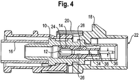
- a coaxial connector according to the invention comprises an outer conductor part 10, an inner conductor part 12, a dielectric 14, a Crimhülse 16, a Kodiergephaseuse 18 and a secondary fuse 20.
- the coaxial connector has a plug-side end 22, which for electrically and mechanically connecting the inner conductor part 12th and outer conductor part 10 is formed in each case with an inner conductor part and outer conductor part of a complementary coaxial connector, not shown.
- an axial channel 24 for axially inserting the inner conductor part 12 into the plug-side end 22 facing away from the end of the dielectric 14 is formed.
- elevations in the form of locking lugs 26 are formed and on a channel 24 facing inside of the dielectric 14 corresponding recesses 28 are formed and arranged such that the locking lugs 26 engage in the recesses 28 when the inner conductor part in a predetermined axial position relative to the outer conductor part.
- the inner conductor part 12 protrudes into the plug-side end 22 in such a way that predetermined connection dimensions are present.
- the channel 24 of the dielectric has a first radial inner diameter 30, which tapers at the plug-side end 22 conically to a smaller, second radial inner diameter 32.
- the inner conductor part 12 has a first outer diameter 34, which tapers to a smaller, second outer diameter 36 such that a shoulder 38 is formed on the outer side of the inner conductor part 12.
- the first outer diameter 34 of the inner conductor part 12 is formed larger than the second inner radial diameter 32 of the channel 24. In this way, the shoulder 38 abuts against the conical taper of the channel 24 at its plug-side end 22 and can then not be moved further in the axial direction.
- the shoulder 38 on the inner conductor part 12 is arranged in such an axial direction that the inner conductor part 12 is located at the predetermined axial position and the locking lugs 26 are already engaged in the recesses 28 when the shoulder 38 at the conical taper of the channel 24 at whose plug-side end 22 abuts.
- This is in Fig. 4 shown.
- an insertion of the inner conductor part 12 in the axial direction over the predetermined axial position beyond in the direction of the plug-side end 22 is effectively avoided even at high axial force. This is Ensure that the connection dimensions at the plug-in end 22 are always correct.
- a coaxial cable (not shown) connectable to the coaxial connector.
Landscapes
- Coupling Device And Connection With Printed Circuit (AREA)
Description
- Die vorliegende Erfindung betrifft einen Koaxialsteckverbinder, insbesondere Koaxialstecker oder Koaxialbuchse, mit einem Außenleiterteil, einem Innenleiterteil, einem Dielektrikum, welches das Innenleiterteil innerhalb und koaxial zum Außenleiterteil an einer vorbestimmten axialen Position hält, und einem steckseitigen Ende zum steckenden elektrischen und mechanischen Verbinden von Innenleiterteil und Außenleiterteil mit jeweils einem Innenleiterteil und einem Außenleiterteil eines komplementären Koaxialsteckverbinders, wobei das Dielektrikum einen axialen Kanal mit einem vorbestimmten ersten radialen Durchmesser aufweist, in dem das Innenleiterteil angeordnet ist, gemäß dem Oberbegriff des Anspruchs 1.
- Bei derartigen Koaxialsteckverbindern ist es üblich zur Montage des Koaxialsteckverbinders das Innenleiterteil axial in den Kanal des Dielektrikums einzuschieben, bis sich das Innenleiterteil an der axialen vorbestimmten Position befindet. In dieser axialen vorbestimmten Position weist der Koaxialsteckverbinder an seinem steckseitigen Ende die korrekten Anschlussmaße auf. Durch Einschieben des Innenleiterteils mit zu hoher axialer Kraft kann es jedoch passieren, dass das Innenleiterteil über die axiale vorbestimmte Position hinaus geschoben wird. Der Koaxialsteckverbinder ist dann beschädigt und eine Übertragung von HF-Signalen über diesen Koaxialsteckverbinder ist nicht mehr einwandfrei möglich. Zusätzlich wird beim Einstecken dieses Koaxialsteckverbinders mit falschen Anschlussmaßen in einen komplementären Koaxialsteckverbinder auch dieser komplementäre Koaxialsteckverbinder beschädigt. Die Folge ist auch hier eine sehr schlechte Übertragung von HF-Signalen.
- Aus der
US 2003/0176104 A1 ist ein Koaxialsteckverbinder mit einem Kunststoffgehäuse bekannt, welcher dem sog. FAKRA-Standardisierungsschema (FAKRA = Fachkreis Automobiltechnik) für SMB-Verbindungen entspricht. Hierbei ist ein Kunststoffgehäuse vorgesehen, welches den Steckverbinder hält, schützt und für den Steckvorgang mit einem anderen Steckverbinder mit Kunststoffgehäuse vorpositioniert. Das Gehäuse weist zusätzlich mechanische Kodierungen auf, so dass nur zusammenpassende Gehäuse ineinander gesteckt werden können. - Derartige Kunststoffgehäuse für Koaxialsteckverbinder, welche auch FAKRA-Gehäuse genannt werden, finden in der Automobiltechnik Anwendung für Datenübertragungskabel. Diese Datenübertragungskabel sind üblicherweise Koaxialkabel oder ähnliche auf einem elektrischen Leiter basierende Kabel. Die mechanischen Abmessungen derartiger FAKRA-Gehäuse im Interface-Bereich, d.h. in einem axialen Abschnitt des Gehäuses, welcher mit einem komplementären Stecker zusammenwirkt, um eine mechanische Verbindung zwischen beiden Kunststoffgehäusen herzustellen, sind in der DIN-Norm 72594-1 in der Fassung vom Oktober 2004 festgelegt. Der Teil "Straßenfahrzeuge - 50-Ohm-Hochfrequenz-Schnittstelle (50-Ω-HFSSt) - Teil 1: Maße und elektrische Anforderungen" der o.g. DIN-Norm 72594-1 legt Stecker und Kuppler einer Schnittstelle mit einer Impedanz von 50 Ohm für Hochfrequenz-Anwendungen (50-Ω-HFSSt) in Straßenfahrzeugen fest und stellt so die Kommunikation zum und vom Kfz sicher. Er legt maßliche und elektrische Anforderungen und Eigenschaften fest und sichert deren Austauschbarkeit. Alle namhaften Autohersteller fertigen nach dieser Norm. Der Inhalt dieser Norm wird von dem Normenausschuss Kraftfahrzeuge (FAKRA) festgelegt.
- Der Normenausschuss Kraftfahrzeuge (FAKRA) im DIN vertritt die regionalen, nationalen und internationalen Normungsinteressen auf dem Gebiet des Kraftfahrzeugwesens. Das Aufgabengebiet des FAKRA umfasst die Erstellung von allen Normen bezüglich Vereinbarkeit, Austauschbarkeit und Sicherheit für Straßenfahrzeuge nach DIN 70010 (ausgenommen Ackerschlepper), unabhängig davon, ob diese Straßenfahrzeuge mit Verbrennungsmotoren, Elektromotoren oder Hybridantrieben ausgerüstet sind. Auch für die Aufbauten dieser Straßenfahrzeuge (ausgenommen Kommunal-, Feuerwehrfahrzeuge und Krankenkraftwagen) erstellt der FAKRA Normen. Ferner ist er zuständig für die Normung der gesamten Ausrüstung vorstehend genannter Fahrzeuge und Aufbauten sowie für die Normung der Frachtcontainer (ISO-Container). Die Normung fördert Rationalisierung und Qualitätssicherung im Kraftfahrzeugbau sowie die Umweltverträglichkeit des Kraftfahrzeugs. Außerdem trägt sie dem aktuellen Stand von Technik und Wissenschaft entsprechend zur Erhöhung der Fahrzeug- und Verkehrssicherheit bei, zum Nutzen der Hersteller und Verbraucher.
- Die
EP 1 811 613 A1 offenbart einen Kuppler nach dem Fakra-Standard für fahrzeugtechnische Anwendungen. Ein Innenleiterteil weist an einer Stelle einen Durchmesser auf, der größer ist als ein Durchmesser des Kanals im Dielektrikum ist. - Die
WO 2005/043683 A2 offenbart Stecker und Kuppler einer koaxialen Steckverbindung in wasserdichter Ausführung. Ein Innenleiterteil mit einem Bund schlägt an einer entsprechend verengten Öffnung des Dielektrikums an. - Die
DE 40 15 092 A1 offenbart einen Steckverbinder mit einer elastischen Rasthülse. - Die
EP 0 657 967 A1 offenbart eine Stiftkupplung zwischen Stecker und Kuppler eines Koaxialkabels. - Die
US 6 491 542 B1 offenbart einen Verbinder für Kraftfahrzeugsteckverbinder. - Der Erfindung liegt die Aufgabe zugrunde, einen Koaxialsteckverbinder der o.g. Art hinsichtlich der Montagesicherheit zu verbessern.
- Diese Aufgabe wird erfindungsgemäß durch einen Koaxialsteckverbinder der o.g. Art mit den in Anspruch 1 gekennzeichneten Merkmalen gelöst. Vorteilhafte Ausgestaltungen der Erfindung sind in den weiteren Ansprüchen beschrieben.
- Bei einem Koaxialsteckverbinder der o.g. Art ist es erfindungsgemäß vorgesehen, dass an oder beabstandet von einem steckseitigen Ende des Dielektrikums der Kanal für das Innenleiterteil derart ausgebildet ist, dass sich der radiale Durchmesser des Kanals in Richtung des steckseitigen Endes von dem ersten vorbestimmten radialen Durchmesser auf einen zweiten vorbestimmten radialen Durchmesser verjüngt, wobei das Innenleiterteil wenigstens einen ersten Durchmesser und einen zweiten Durchmesser, welcher kleiner als der erste Durchmesser sowie kleiner als der zweite vorbestimmte radiale Durchmesser des Kanals des Dielektrikums ist, aufweist, wobei der erste Durchmesser des Innenleiterteils derart gewählt ist, dass das Innenleiterteil in den ersten vorbestimmten radialen Durchmesser des Kanals passt und gleichzeitig der erste Durchmesser des Innenleiterteils größer als der zweite vorbestimmte radiale Durchmesser des Kanals ist, so dass sich an einer Außenseite des Innenleiterteils an der Stelle, an der der erste Durchmesser des Innenleiterteils in den zweiten Durchmesser des Innenleiterteils übergeht, eine Schulter ausgebildet ist, wobei diese Schulter an der Außenseite des Innenleiterteils in axialer Richtung derart angeordnet ist, dass sich das Innenleiterteil an der vorbestimmten axialen Position innerhalb des Außenleiterteils befindet, wenn die Schulter des Innenleiterteils an der Verjüngung des radialen Durchmessers des Kanals des Dielektrikums anschlägt.
- Dies hat den Vorteil, dass ein Durchschiebeschutz in axialer Richtung für das Innenleiterteil zur Verfügung steht, der auch hohen axialen Kräften bei der Montage des Koaxialsteckverbinders widersteht.
- Eine zusätzliche Funktion für das axial korrekte Positionieren des Innenleiterteils steht dadurch zur Verfügung, dass an einer Außenseite des Innenleiterteils wenigstens eine Erhebung vorgesehenen ist und an einer Innenseite des Dielektrikums, welche dem Kanal zugewandt ist, wenigstens eine Ausnehmung derart angeordnet und ausgebildet ist, dass die Erhebung am Innenleiterteil mit der Ausnehmung am Dielektrikum verrastet, wenn das Innenleiterteil axial in den Kanal des Dielektrikums bis zu der vorbestimmten Position eingeschoben ist.
- Zweckmäßigerweise erstreckt sich die Schulter an der Außenseite des Innenleiterteils in Umfangsrichtung über den gesamten Umfang des Innenleiterteils.
- In einer bevorzugten Ausführungsform weist der Koaxialsteckverbinder zusätzlich ein Kodiergehäuse auf, welches in seinem Interfacebereich mechanische Abmessungen aufweist, die dem FAKRA-Standardisierungsschema für 50-Ω-HFSSt entsprechen.
- Die Erfindung wird im Folgenden anhand der Zeichnung näher erläutert. Diese zeigt in:
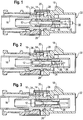
- Fig.1
- eine bevorzugte Ausführungsform eines erfindungsgemäßen Koaxialsteckverbinders in Schnittansicht, wobei ein Innenleiterteil axial bis zu einer ersten axialen Position in ein Dielektrikum eingeschoben ist,
- Fig. 2
- die bevorzugte Ausführungsform eines erfindungsgemäßen Koaxialsteckverbinders gemäß
Fig. 1 in Schnittansicht, wobei das Innenleiterteil axial bis zu einer zweiten axialen Position in das Dielektrikum eingeschoben ist, - Fig.3
- die bevorzugte Ausführungsform eines erfindungsgemäßen Koaxialsteckverbinders gemäß
Fig. 1 in Schnittansicht, wobei das Innenleiterteil axial bis zu einer dritten axialen Position in das Dielektrikum eingeschoben ist, bei der Rastnasen an einer Außenseite des Innenleiterteils in Ausnehmungen an einer Innenseite des Dielektrikums einrasten und - Fig. 4
- die bevorzugte Ausführungsform eines erfindungsgemäßen Koaxialsteckverbinders gemäß
Fig. 1 in Schnittansicht, wobei das Innenleiterteil axial bis zu einer vierten axialen Position in das Dielektrikum eingeschoben ist, bei der eine an einer Außenseite des Innenleiterteils ausgebildete Schulter an einer Durchmesserverjüngung im Dielektrikum anschlägt. - Die in den
Fig. 1 bis 4 dargestellte, bevorzugte Ausführungsform eines erfindungsgemäßen Koaxialsteckverbinders umfasst ein Außenleiterteil 10, ein Innenleiterteil 12, ein Dielektrikum 14, eine Crimphülse 16, ein Kodiergehäuse 18 und eine Sekundärsicherung 20. Der Koaxialsteckverbinder weist ein steckseitiges Ende 22 auf, welches zum elektrischen und mechanischen Verbinden des Innenleiterteils 12 sowie Außenleiterteils 10 jeweils mit einem Innenleiterteil und Außenleiterteil eines nicht dargestellten komplementären Koaxialsteckverbinders ausgebildet ist. - In dem Dielektrikum 14 ist ein axialer Kanal 24 zum axialen Einschieben des Innenleiterteils 12 in das dem steckseitigen Ende 22 abgewandten Ende des Dielektrikums 14 ausgebildet. Auf einer Außenseite des Innenleiterteils 12 sind Erhebungen in Form von Rastnasen 26 ausgebildet und an einer dem Kanal 24 zugewandten Innenseite des Dielektrikums 14 sind entsprechende Ausnehmungen 28 derart ausgebildet und angeordnet, dass die Rastnasen 26 in die Ausnehmungen 28 einrasten, wenn sich das Innenleiterteil in einer vorbestimmten axialen Position relativ zum Außenleiterteil befindet. In dieser vorbestimmten axialen Position ragt das Innenleiterteil 12 derart in das steckseitige Ende 22, dass vorbestimmte Anschlussmaße vorhanden sind. Bei der Montage des Koaxialsteckverbinders wird das Innenleiterteil 12 von der dem steckseitigen Ende 22 abgewandten Ende her in das Dielektrikum 14 axial eingeschoben, bis die Rastnasen 26 spürbar und hörbar in die Ausnehmungen 28 einrasten.
- Der Kanal 24 des Dielektrikums weist einen ersten radialen Innendurchmesser 30 auf, welcher sich an dem steckseitigen Ende 22 konisch zu einem kleineren, zweiten radialen Innendurchmesser 32 verjüngt. Zusätzlich weist das Innenleiterteil 12 einen ersten Außendurchmesser 34 auf, welcher sich zu einem kleineren, zweiten Außendurchmesser 36 derart verjüngt, dass an der Außenseite des Innenleiterteils 12 eine Schulter 38 ausgebildet ist. Der erste Außendurchmesser 34 des Innenleiterteils 12 ist größer als der zweite radiale Innendurchmesser 32 des Kanals 24 ausgebildet. Auf diese Weise schlägt die Schulter 38 an der konischen Verjüngung des Kanals 24 an dessen steckseitigen Ende 22 an und kann dann in axialer Richtung nicht weiter verschoben werden. Die Schulter 38 auf dem Innenleiterteil 12 ist dabei derart in axialer Richtung angeordnet, dass sich das Innenleiterteil 12 an der vorbestimmten axialen Position befindet und die Rastnasen 26 in die Ausnehmungen 28 bereits eingerastet sind, wenn die Schulter 38 an der konischen Verjüngung des Kanals 24 an dessen steckseitigen Ende 22 anschlägt. Dies ist in
Fig. 4 dargestellt. Auf diese Weise ist ein Einschieben des Innenleiterteils 12 in axialer Richtung über die vorbestimmte axiale Position hinaus in Richtung des steckseitigen Endes 22 auch bei hoher axialer Kraft wirksam vermieden. Dadurch ist sichergestellt, dass die Anschlussabmessungen am steckseitigen Ende 22 immer korrekt sind. - An dem dem steckseitigen Ende 22 gegenüberliegenden Ende des Koaxialsteckverbinders mit der Crimphülse 16 ist ein Koaxialkabel (nicht dargestellt) mit dem Koaxialsteckverbinder verbindbar.
Claims (3)
- Koaxialsteckverbinder, insbesondere Koaxialstecker oder Koaxialbuchse, mit einem Außenleiterteil (10), einem Innenleiterteil (12), einem Dielektrikum (14), welches das Innenleiterteil (12) innerhalb und koaxial zum Außenleiterteil (10) an einer vorbestimmten axialen Position hält, und einem steckseitigen Ende (22) zum steckenden elektrischen und mechanischen Verbinden von Innenleiterteil (12) und Außenleiterteil (10) mit jeweils einem Innenleiterteil und einem Außenleiterteil eines komplementären Koaxialsteckverbinders, wobei das Dielektrikum (14) einen axialen Kanal (24) mit einem vorbestimmten ersten radialen Durchmesser (30) aufweist, in dem das Innenleiterteil (12) angeordnet ist, wobei der Kanal (24) derart ausgebildet ist, dass sich der radiale Durchmesser des Kanals (24) in Richtung des steckseitigen Endes (22) von dem ersten vorbestimmten radialen Durchmesser (30) auf einen zweiten vorbestimmten radialen Durchmesser (32) verjüngt, wobei das Innenleiterteil (12) wenigstens einen ersten Durchmesser (34) und einen zweiten Durchmesser (36), welcher kleiner als der erste Durchmesser (34) sowie kleiner als der zweite vorbestimmte radiale Durchmesser (32) des Kanals (24) des Dielektrikums (14) ist, aufweist, wobei der erste Durchmesser (34) des Innenleiterteils (12) derart gewählt ist, dass das Innenleiterteil (12) in den ersten vorbestimmten radialen Durchmesser (30) des Kanals (24) passt und gleichzeitig der erste Durchmesser (34) des Innenleiterteils (12) größer als der zweite vorbestimmte radiale Durchmesser (32) des Kanals (24) ist, so dass an einer Außenseite des Innenleiterteils (12) an der Stelle, an der der erste Durchmesser (34) des Innenleiterteils (12) in den zweiten Durchmesser (36) des Innenleiterteils (12) übergeht, eine Schulter (38) ausgebildet ist, wobei diese Schulter (38) an der Außenseite des Innenleiterteils (12) in axialer Richtung derart angeordnet ist, dass sich das Innenleiterteil (12) an der vorbestimmten axialen Position innerhalb des Außenleiterteils (10) befindet, wenn die Schulter (38) des Innenleiterteils (12) an der Verjüngung des radialen Durchmessers (30, 32) des Kanals (24) des Dielektrikums (14) anschlägt,
wobei an einer Außenseite des Innenleiterteils (12) wenigstens eine Erhebung (26) vorgesehenen ist und an einer Innenseite des Dielektrikums (14), welche dem Kanal (24) zugewandt ist, wenigstens eine Ausnehmung (28) derart angeordnet und ausgebildet ist, dass die Erhebung (26) am Innenleiterteil (12) mit der Ausnehmung (28) am Dielektrikum (14) verrastet, wenn das Innenleiterteil (12) axial in den Kanal (24) des Dielektrikums (14) bis zu der vorbestimmten Position eingeschoben ist, dadurch gekennzeichnet, dass sich der erste Durchmesser (30) des Kanals (24) an dem steckseitigen Ende (22) des Dielektrikums (14) konisch zu dem zweiten Durchmesser (32) verjüngt. - Koaxialsteckverbinder nach Anspruch 1, dadurch gekennzeichnet, dass sich die Schulter (38) an der Außenseite des Innenleiterteils (12) in Umfangsrichtung über den gesamten Umfang des Innenleiterteils (12) erstreckt.
- Koaxialsteckverbinder nach wenigstens einem der vorhergehenden Ansprüche, dadurch gekennzeichnet, dass der Koaxialsteckverbinder zusätzlich ein Kodiergehäuse (18) aufweist, welches in seinem Interfacebereich mechanische Abmessungen aufweist, die dem FAKRA-Standardisierungsschema für 50-Ω-HFSSt entsprechen.
Applications Claiming Priority (2)
| Application Number | Priority Date | Filing Date | Title |
|---|---|---|---|
| DE202007017309U DE202007017309U1 (de) | 2007-12-12 | 2007-12-12 | Koaxialsteckverbinder |
| PCT/EP2008/010301 WO2009074263A1 (de) | 2007-12-12 | 2008-12-04 | Koaxialsteckverbinder |
Publications (2)
| Publication Number | Publication Date |
|---|---|
| EP2220726A1 EP2220726A1 (de) | 2010-08-25 |
| EP2220726B1 true EP2220726B1 (de) | 2016-04-13 |
Family
ID=39135032
Family Applications (1)
| Application Number | Title | Priority Date | Filing Date |
|---|---|---|---|
| EP08860569.6A Active EP2220726B1 (de) | 2007-12-12 | 2008-12-04 | Koaxialsteckverbinder |
Country Status (9)
| Country | Link |
|---|---|
| US (1) | US8043117B2 (de) |
| EP (1) | EP2220726B1 (de) |
| JP (1) | JP5255650B2 (de) |
| CN (1) | CN101884142B (de) |
| CA (1) | CA2708612C (de) |
| DE (1) | DE202007017309U1 (de) |
| HK (1) | HK1146600A1 (de) |
| TW (1) | TWM355486U (de) |
| WO (1) | WO2009074263A1 (de) |
Families Citing this family (10)
| Publication number | Priority date | Publication date | Assignee | Title |
|---|---|---|---|---|
| DE202008015000U1 (de) * | 2008-11-12 | 2009-01-29 | Rosenberger Hochfrequenztechnik Gmbh & Co. Kg | HF-Steckverbinder |
| DE102010014981A1 (de) * | 2010-04-14 | 2011-10-20 | Pfisterer Kontaktsysteme Gmbh | Vorrichtung zum elektrischen Verbinden eines Kabels, insbesondere Steckverbindungsteil |
| CN102386503A (zh) * | 2011-08-25 | 2012-03-21 | 合肥佰特微波技术有限公司 | 一种外导体为整体式的同轴电缆连接器 |
| DE102011113062A1 (de) * | 2011-09-09 | 2013-03-14 | Amphenol-Tuchel Electronics Gmbh | Kontaktgeschützter Steckverbinder |
| DK2680372T3 (en) * | 2012-06-29 | 2017-09-11 | Corning Optical Comm Rf Llc | Multiple section insulator for coaxial connector |
| CN102801014B (zh) * | 2012-08-07 | 2014-08-27 | 上海航天科工电器研究院有限公司 | 一种用于涡流检测设备的连接器插座 |
| EP3289647A4 (de) * | 2015-05-01 | 2018-12-26 | Commscope Technologies LLC | Koaxialkabelverbinderschnittstelle zur verhinderung der kopplung mit einem falschen steckverbinder |
| DE102016109266A1 (de) | 2016-05-06 | 2017-11-09 | Rosenberger Hochfrequenztechnik Gmbh & Co. Kg | Steckverbindungsvorrichtung mit wenigstens einem Steckverbinder |
| CN106711657B (zh) * | 2017-03-08 | 2022-07-05 | 国网河南省电力公司漯河供电公司 | 一种分体式2m接头及其制作方法 |
| US10992087B2 (en) | 2018-12-13 | 2021-04-27 | Amphenol Corporation | Contact member for electrical connector |
Family Cites Families (15)
| Publication number | Priority date | Publication date | Assignee | Title |
|---|---|---|---|---|
| JPS549977Y2 (de) * | 1974-08-19 | 1979-05-10 | ||
| DE4015092A1 (de) * | 1990-05-11 | 1991-11-14 | Hirschmann Richard Gmbh Co | Steckverbinder |
| JPH0423081U (de) * | 1990-06-14 | 1992-02-25 | ||
| ES2081207T3 (es) * | 1992-02-14 | 1996-02-16 | Itt Ind Ltd | Disposicion de terminal de un conductor electrico. |
| IT1270760B (it) * | 1993-12-13 | 1997-05-07 | Massimo Calearo | Innesto a spina per il bloccaggio del collegamento tra un connettore maschio ed un connettore femmina in un cavo coassiale |
| JPH11289651A (ja) * | 1998-04-01 | 1999-10-19 | Nissin High Voltage Co Ltd | イオン源用コネクタ |
| US6491542B1 (en) * | 2002-01-16 | 2002-12-10 | Yazaki North America | Combined connection and terminal position assurance structure for vehicle wiring connectors |
| US6575786B1 (en) * | 2002-01-18 | 2003-06-10 | Adc Telecommunications, Inc. | Triaxial connector and method |
| US6676445B2 (en) * | 2002-01-25 | 2004-01-13 | Tyco Electronics Corporation | Coaxial cable connector apparatus, methods and articles of manufacture for angle or in-line applications |
| US20030176104A1 (en) * | 2002-03-13 | 2003-09-18 | Hall John W. | Apparatus and method for electrical connector cable retention |
| US6769933B2 (en) * | 2002-11-27 | 2004-08-03 | Corning Gilbert Inc. | Coaxial cable connector and related methods |
| CN1853318A (zh) * | 2003-09-20 | 2006-10-25 | 赫希曼电子有限及两合公司 | 按防水设计的同轴插塞连接装置的插头和联接器 |
| US7329149B2 (en) * | 2004-01-26 | 2008-02-12 | John Mezzalingua Associates, Inc. | Clamping and sealing mechanism with multiple rings for cable connector |
| DE102005007589B3 (de) * | 2005-02-18 | 2006-06-14 | Kathrein-Werke Kg | Koaxialsteckverbinder |
| DE102006003236A1 (de) * | 2006-01-24 | 2007-07-26 | Hirschmann Car Communication Gmbh | Kuppler, insbesondere Winkelkuppler nach dem Fakra-Standard, für fahrzeugtechnische Anwendungen |
-
2007
- 2007-12-12 DE DE202007017309U patent/DE202007017309U1/de not_active Expired - Lifetime
-
2008
- 2008-12-04 WO PCT/EP2008/010301 patent/WO2009074263A1/de active Application Filing
- 2008-12-04 US US12/747,370 patent/US8043117B2/en active Active
- 2008-12-04 CN CN2008801187817A patent/CN101884142B/zh active Active
- 2008-12-04 JP JP2010537298A patent/JP5255650B2/ja not_active Expired - Fee Related
- 2008-12-04 EP EP08860569.6A patent/EP2220726B1/de active Active
- 2008-12-04 CA CA2708612A patent/CA2708612C/en not_active Expired - Fee Related
- 2008-12-09 TW TW097221986U patent/TWM355486U/zh not_active IP Right Cessation
-
2011
- 2011-01-25 HK HK11100731.1A patent/HK1146600A1/xx not_active IP Right Cessation
Also Published As
| Publication number | Publication date |
|---|---|
| JP5255650B2 (ja) | 2013-08-07 |
| CN101884142B (zh) | 2013-01-23 |
| US8043117B2 (en) | 2011-10-25 |
| EP2220726A1 (de) | 2010-08-25 |
| TWM355486U (en) | 2009-04-21 |
| CA2708612C (en) | 2015-01-27 |
| WO2009074263A1 (de) | 2009-06-18 |
| DE202007017309U1 (de) | 2008-02-28 |
| CA2708612A1 (en) | 2009-06-18 |
| JP2011507168A (ja) | 2011-03-03 |
| US20100261379A1 (en) | 2010-10-14 |
| CN101884142A (zh) | 2010-11-10 |
| HK1146600A1 (en) | 2011-06-24 |
Similar Documents
| Publication | Publication Date | Title |
|---|---|---|
| EP2220726B1 (de) | Koaxialsteckverbinder | |
| EP2220730B1 (de) | Koaxialsteckverbinder mit einem kodiergehäuse | |
| EP2361451B1 (de) | Hf-winkelsteckverbinder | |
| EP1866686B1 (de) | Optische datenübertragungskabelsteckerverbindung mit fakra-gehäuse | |
| EP1652275B1 (de) | Koaxialstecker für einen koaxialsteckverbinder | |
| EP2347475B1 (de) | Hf-steckverbinder | |
| EP1825575B1 (de) | Isolierteil für hf-steckverbinder, insbesondere fakra-steckverbinder | |
| EP3745541B1 (de) | Steckdose für eine kombinierte elektrische verbindung und datenverbindung | |
| EP2311154A1 (de) | Datenkabel | |
| EP1861898B1 (de) | Steckverbinder | |
| KR20200070612A (ko) | 커넥터 | |
| DE202005009962U1 (de) | Isolierteil für HF-Steckverbinder, insbesondere FAKRA-Steckverbinder | |
| EP1797621B1 (de) | Koaxialsteckverbinder für ein koaxialkabel | |
| DE202008014541U1 (de) | Steckverbinder mit einem Kodiergehäuse | |
| DE102018126448A1 (de) | Elektrischer Steckverbinder und elektrische Steckverbindung | |
| EP3713018B1 (de) | Elektrischer steckverbinder | |
| DE10339965B3 (de) | Winkelkuppler | |
| EP3671975A1 (de) | Kabelsteckverbinderanordnung, kabelsteckverbinder und pressmittel | |
| DE102009052353A1 (de) | Kontaktstecker | |
| WO2015117695A1 (de) | Elektrisches gerät und verbindungsanordnung mit einem elektrischen gerät | |
| WO2022184412A1 (de) | Schaltmodul ausgebildet mit einer abgedichteten schnittstelle | |
| EP0856920B1 (de) | Steckverbindung aus Stecker und Steckdose, vorzugsweise für die elektrische Versorgung von Kraftfahrzeuganhängern | |
| EP1617505A1 (de) | Kabelsatz, insbesondere für die Anwendung in einem Fahrzeug |
Legal Events
| Date | Code | Title | Description |
|---|---|---|---|
| PUAI | Public reference made under article 153(3) epc to a published international application that has entered the european phase |
Free format text: ORIGINAL CODE: 0009012 |
|
| 17P | Request for examination filed |
Effective date: 20100401 |
|
| AK | Designated contracting states |
Kind code of ref document: A1 Designated state(s): AT BE BG CH CY CZ DE DK EE ES FI FR GB GR HR HU IE IS IT LI LT LU LV MC MT NL NO PL PT RO SE SI SK TR |
|
| AX | Request for extension of the european patent |
Extension state: AL BA MK RS |
|
| DAX | Request for extension of the european patent (deleted) | ||
| 17Q | First examination report despatched |
Effective date: 20140718 |
|
| REG | Reference to a national code |
Ref country code: DE Ref legal event code: R079 Ref document number: 502008014103 Country of ref document: DE Free format text: PREVIOUS MAIN CLASS: H01R0013410000 Ipc: H01R0009050000 |
|
| GRAP | Despatch of communication of intention to grant a patent |
Free format text: ORIGINAL CODE: EPIDOSNIGR1 |
|
| RIC1 | Information provided on ipc code assigned before grant |
Ipc: H01R 103/00 20060101ALI20151113BHEP Ipc: H01R 13/64 20060101ALI20151113BHEP Ipc: H01R 13/41 20060101ALI20151113BHEP Ipc: H01R 9/05 20060101AFI20151113BHEP Ipc: H01R 24/40 20110101ALI20151113BHEP Ipc: H01R 13/646 20110101ALI20151113BHEP |
|
| INTG | Intention to grant announced |
Effective date: 20151204 |
|
| GRAS | Grant fee paid |
Free format text: ORIGINAL CODE: EPIDOSNIGR3 |
|
| GRAA | (expected) grant |
Free format text: ORIGINAL CODE: 0009210 |
|
| AK | Designated contracting states |
Kind code of ref document: B1 Designated state(s): AT BE BG CH CY CZ DE DK EE ES FI FR GB GR HR HU IE IS IT LI LT LU LV MC MT NL NO PL PT RO SE SI SK TR |
|
| REG | Reference to a national code |
Ref country code: GB Ref legal event code: FG4D Free format text: NOT ENGLISH |
|
| REG | Reference to a national code |
Ref country code: AT Ref legal event code: REF Ref document number: 791025 Country of ref document: AT Kind code of ref document: T Effective date: 20160415 Ref country code: CH Ref legal event code: EP |
|
| REG | Reference to a national code |
Ref country code: IE Ref legal event code: FG4D Free format text: LANGUAGE OF EP DOCUMENT: GERMAN |
|
| REG | Reference to a national code |
Ref country code: DE Ref legal event code: R096 Ref document number: 502008014103 Country of ref document: DE |
|
| REG | Reference to a national code |
Ref country code: SE Ref legal event code: TRGR |
|
| REG | Reference to a national code |
Ref country code: LT Ref legal event code: MG4D |
|
| REG | Reference to a national code |
Ref country code: NL Ref legal event code: MP Effective date: 20160413 |
|
| PG25 | Lapsed in a contracting state [announced via postgrant information from national office to epo] |
Ref country code: PL Free format text: LAPSE BECAUSE OF FAILURE TO SUBMIT A TRANSLATION OF THE DESCRIPTION OR TO PAY THE FEE WITHIN THE PRESCRIBED TIME-LIMIT Effective date: 20160413 Ref country code: NO Free format text: LAPSE BECAUSE OF FAILURE TO SUBMIT A TRANSLATION OF THE DESCRIPTION OR TO PAY THE FEE WITHIN THE PRESCRIBED TIME-LIMIT Effective date: 20160713 Ref country code: LT Free format text: LAPSE BECAUSE OF FAILURE TO SUBMIT A TRANSLATION OF THE DESCRIPTION OR TO PAY THE FEE WITHIN THE PRESCRIBED TIME-LIMIT Effective date: 20160413 Ref country code: FI Free format text: LAPSE BECAUSE OF FAILURE TO SUBMIT A TRANSLATION OF THE DESCRIPTION OR TO PAY THE FEE WITHIN THE PRESCRIBED TIME-LIMIT Effective date: 20160413 Ref country code: NL Free format text: LAPSE BECAUSE OF FAILURE TO SUBMIT A TRANSLATION OF THE DESCRIPTION OR TO PAY THE FEE WITHIN THE PRESCRIBED TIME-LIMIT Effective date: 20160413 |
|
| PG25 | Lapsed in a contracting state [announced via postgrant information from national office to epo] |
Ref country code: GR Free format text: LAPSE BECAUSE OF FAILURE TO SUBMIT A TRANSLATION OF THE DESCRIPTION OR TO PAY THE FEE WITHIN THE PRESCRIBED TIME-LIMIT Effective date: 20160714 Ref country code: PT Free format text: LAPSE BECAUSE OF FAILURE TO SUBMIT A TRANSLATION OF THE DESCRIPTION OR TO PAY THE FEE WITHIN THE PRESCRIBED TIME-LIMIT Effective date: 20160816 Ref country code: ES Free format text: LAPSE BECAUSE OF FAILURE TO SUBMIT A TRANSLATION OF THE DESCRIPTION OR TO PAY THE FEE WITHIN THE PRESCRIBED TIME-LIMIT Effective date: 20160413 Ref country code: LV Free format text: LAPSE BECAUSE OF FAILURE TO SUBMIT A TRANSLATION OF THE DESCRIPTION OR TO PAY THE FEE WITHIN THE PRESCRIBED TIME-LIMIT Effective date: 20160413 Ref country code: HR Free format text: LAPSE BECAUSE OF FAILURE TO SUBMIT A TRANSLATION OF THE DESCRIPTION OR TO PAY THE FEE WITHIN THE PRESCRIBED TIME-LIMIT Effective date: 20160413 |
|
| REG | Reference to a national code |
Ref country code: FR Ref legal event code: PLFP Year of fee payment: 9 |
|
| REG | Reference to a national code |
Ref country code: DE Ref legal event code: R097 Ref document number: 502008014103 Country of ref document: DE |
|
| PG25 | Lapsed in a contracting state [announced via postgrant information from national office to epo] |
Ref country code: RO Free format text: LAPSE BECAUSE OF FAILURE TO SUBMIT A TRANSLATION OF THE DESCRIPTION OR TO PAY THE FEE WITHIN THE PRESCRIBED TIME-LIMIT Effective date: 20160413 Ref country code: SK Free format text: LAPSE BECAUSE OF FAILURE TO SUBMIT A TRANSLATION OF THE DESCRIPTION OR TO PAY THE FEE WITHIN THE PRESCRIBED TIME-LIMIT Effective date: 20160413 Ref country code: EE Free format text: LAPSE BECAUSE OF FAILURE TO SUBMIT A TRANSLATION OF THE DESCRIPTION OR TO PAY THE FEE WITHIN THE PRESCRIBED TIME-LIMIT Effective date: 20160413 Ref country code: CZ Free format text: LAPSE BECAUSE OF FAILURE TO SUBMIT A TRANSLATION OF THE DESCRIPTION OR TO PAY THE FEE WITHIN THE PRESCRIBED TIME-LIMIT Effective date: 20160413 Ref country code: DK Free format text: LAPSE BECAUSE OF FAILURE TO SUBMIT A TRANSLATION OF THE DESCRIPTION OR TO PAY THE FEE WITHIN THE PRESCRIBED TIME-LIMIT Effective date: 20160413 |
|
| PLBE | No opposition filed within time limit |
Free format text: ORIGINAL CODE: 0009261 |
|
| STAA | Information on the status of an ep patent application or granted ep patent |
Free format text: STATUS: NO OPPOSITION FILED WITHIN TIME LIMIT |
|
| 26N | No opposition filed |
Effective date: 20170116 |
|
| PG25 | Lapsed in a contracting state [announced via postgrant information from national office to epo] |
Ref country code: SI Free format text: LAPSE BECAUSE OF FAILURE TO SUBMIT A TRANSLATION OF THE DESCRIPTION OR TO PAY THE FEE WITHIN THE PRESCRIBED TIME-LIMIT Effective date: 20160413 Ref country code: BE Free format text: LAPSE BECAUSE OF NON-PAYMENT OF DUE FEES Effective date: 20161231 |
|
| REG | Reference to a national code |
Ref country code: CH Ref legal event code: PL |
|
| PG25 | Lapsed in a contracting state [announced via postgrant information from national office to epo] |
Ref country code: MC Free format text: LAPSE BECAUSE OF FAILURE TO SUBMIT A TRANSLATION OF THE DESCRIPTION OR TO PAY THE FEE WITHIN THE PRESCRIBED TIME-LIMIT Effective date: 20160413 |
|
| REG | Reference to a national code |
Ref country code: IE Ref legal event code: MM4A |
|
| PG25 | Lapsed in a contracting state [announced via postgrant information from national office to epo] |
Ref country code: LU Free format text: LAPSE BECAUSE OF NON-PAYMENT OF DUE FEES Effective date: 20161204 Ref country code: CH Free format text: LAPSE BECAUSE OF NON-PAYMENT OF DUE FEES Effective date: 20161231 Ref country code: LI Free format text: LAPSE BECAUSE OF NON-PAYMENT OF DUE FEES Effective date: 20161231 |
|
| PG25 | Lapsed in a contracting state [announced via postgrant information from national office to epo] |
Ref country code: IE Free format text: LAPSE BECAUSE OF NON-PAYMENT OF DUE FEES Effective date: 20161204 |
|
| REG | Reference to a national code |
Ref country code: FR Ref legal event code: PLFP Year of fee payment: 10 |
|
| REG | Reference to a national code |
Ref country code: BE Ref legal event code: MM Effective date: 20161231 |
|
| REG | Reference to a national code |
Ref country code: AT Ref legal event code: MM01 Ref document number: 791025 Country of ref document: AT Kind code of ref document: T Effective date: 20161204 |
|
| PG25 | Lapsed in a contracting state [announced via postgrant information from national office to epo] |
Ref country code: AT Free format text: LAPSE BECAUSE OF NON-PAYMENT OF DUE FEES Effective date: 20161204 Ref country code: CY Free format text: LAPSE BECAUSE OF FAILURE TO SUBMIT A TRANSLATION OF THE DESCRIPTION OR TO PAY THE FEE WITHIN THE PRESCRIBED TIME-LIMIT Effective date: 20160413 Ref country code: HU Free format text: LAPSE BECAUSE OF FAILURE TO SUBMIT A TRANSLATION OF THE DESCRIPTION OR TO PAY THE FEE WITHIN THE PRESCRIBED TIME-LIMIT; INVALID AB INITIO Effective date: 20081204 |
|
| PG25 | Lapsed in a contracting state [announced via postgrant information from national office to epo] |
Ref country code: IS Free format text: LAPSE BECAUSE OF FAILURE TO SUBMIT A TRANSLATION OF THE DESCRIPTION OR TO PAY THE FEE WITHIN THE PRESCRIBED TIME-LIMIT Effective date: 20160413 Ref country code: TR Free format text: LAPSE BECAUSE OF FAILURE TO SUBMIT A TRANSLATION OF THE DESCRIPTION OR TO PAY THE FEE WITHIN THE PRESCRIBED TIME-LIMIT Effective date: 20160413 |
|
| PG25 | Lapsed in a contracting state [announced via postgrant information from national office to epo] |
Ref country code: BG Free format text: LAPSE BECAUSE OF FAILURE TO SUBMIT A TRANSLATION OF THE DESCRIPTION OR TO PAY THE FEE WITHIN THE PRESCRIBED TIME-LIMIT Effective date: 20160413 |
|
| PG25 | Lapsed in a contracting state [announced via postgrant information from national office to epo] |
Ref country code: MT Free format text: LAPSE BECAUSE OF FAILURE TO SUBMIT A TRANSLATION OF THE DESCRIPTION OR TO PAY THE FEE WITHIN THE PRESCRIBED TIME-LIMIT Effective date: 20160413 |
|
| P01 | Opt-out of the competence of the unified patent court (upc) registered |
Effective date: 20230523 |
|
| REG | Reference to a national code |
Ref country code: DE Ref legal event code: R082 Ref document number: 502008014103 Country of ref document: DE Representative=s name: KANDLBINDER, MARKUS, DIPL.-PHYS., DE |
|
| PGFP | Annual fee paid to national office [announced via postgrant information from national office to epo] |
Ref country code: GB Payment date: 20231219 Year of fee payment: 16 |
|
| PGFP | Annual fee paid to national office [announced via postgrant information from national office to epo] |
Ref country code: SE Payment date: 20231222 Year of fee payment: 16 Ref country code: IT Payment date: 20231221 Year of fee payment: 16 Ref country code: FR Payment date: 20231226 Year of fee payment: 16 |
|
| PGFP | Annual fee paid to national office [announced via postgrant information from national office to epo] |
Ref country code: DE Payment date: 20231227 Year of fee payment: 16 |