EP2219778B1 - Verfahren zur durchführung chemischer reaktionen mit hilfe eines induktiv erwärmten heizmediums - Google Patents
Verfahren zur durchführung chemischer reaktionen mit hilfe eines induktiv erwärmten heizmediums Download PDFInfo
- Publication number
- EP2219778B1 EP2219778B1 EP08859853A EP08859853A EP2219778B1 EP 2219778 B1 EP2219778 B1 EP 2219778B1 EP 08859853 A EP08859853 A EP 08859853A EP 08859853 A EP08859853 A EP 08859853A EP 2219778 B1 EP2219778 B1 EP 2219778B1
- Authority
- EP
- European Patent Office
- Prior art keywords
- reaction
- heating medium
- medium
- reactor
- heating
- Prior art date
- Legal status (The legal status is an assumption and is not a legal conclusion. Google has not performed a legal analysis and makes no representation as to the accuracy of the status listed.)
- Not-in-force
Links
- 238000010438 heat treatment Methods 0.000 title claims abstract description 130
- 238000006243 chemical reaction Methods 0.000 title claims abstract description 84
- 238000000034 method Methods 0.000 title claims abstract description 47
- 239000012429 reaction media Substances 0.000 claims abstract description 77
- 239000000376 reactant Substances 0.000 claims abstract description 43
- 239000007787 solid Substances 0.000 claims abstract description 32
- 230000005674 electromagnetic induction Effects 0.000 claims abstract description 29
- 150000001875 compounds Chemical class 0.000 claims abstract description 18
- 239000000126 substance Substances 0.000 claims abstract description 14
- 239000002245 particle Substances 0.000 claims description 47
- 230000008569 process Effects 0.000 claims description 26
- 239000000463 material Substances 0.000 claims description 17
- 239000000203 mixture Substances 0.000 claims description 10
- 239000007788 liquid Substances 0.000 claims description 9
- 230000005294 ferromagnetic effect Effects 0.000 claims description 8
- 125000004429 atom Chemical group 0.000 claims description 5
- 125000004432 carbon atom Chemical group C* 0.000 claims description 4
- 229910052739 hydrogen Inorganic materials 0.000 claims description 4
- 229910052757 nitrogen Inorganic materials 0.000 claims description 4
- 229910052787 antimony Inorganic materials 0.000 claims description 2
- 229910052785 arsenic Inorganic materials 0.000 claims description 2
- 229910052797 bismuth Inorganic materials 0.000 claims description 2
- 229910052796 boron Inorganic materials 0.000 claims description 2
- 229910052732 germanium Inorganic materials 0.000 claims description 2
- 229910052736 halogen Inorganic materials 0.000 claims description 2
- 150000002367 halogens Chemical class 0.000 claims description 2
- 229910052745 lead Inorganic materials 0.000 claims description 2
- 239000000696 magnetic material Substances 0.000 claims description 2
- 229910052760 oxygen Inorganic materials 0.000 claims description 2
- 229910052698 phosphorus Inorganic materials 0.000 claims description 2
- 229910052710 silicon Inorganic materials 0.000 claims description 2
- 229910052717 sulfur Inorganic materials 0.000 claims description 2
- 229910052718 tin Inorganic materials 0.000 claims description 2
- 229910052799 carbon Inorganic materials 0.000 claims 1
- YXFVVABEGXRONW-UHFFFAOYSA-N Toluene Chemical compound CC1=CC=CC=C1 YXFVVABEGXRONW-UHFFFAOYSA-N 0.000 description 30
- 239000003054 catalyst Substances 0.000 description 25
- VYPSYNLAJGMNEJ-UHFFFAOYSA-N Silicium dioxide Chemical compound O=[Si]=O VYPSYNLAJGMNEJ-UHFFFAOYSA-N 0.000 description 21
- 239000000047 product Substances 0.000 description 15
- 238000001816 cooling Methods 0.000 description 14
- 239000000243 solution Substances 0.000 description 13
- ZMXDDKWLCZADIW-UHFFFAOYSA-N N,N-Dimethylformamide Chemical compound CN(C)C=O ZMXDDKWLCZADIW-UHFFFAOYSA-N 0.000 description 12
- 239000006247 magnetic powder Substances 0.000 description 12
- RTZKZFJDLAIYFH-UHFFFAOYSA-N Diethyl ether Chemical compound CCOCC RTZKZFJDLAIYFH-UHFFFAOYSA-N 0.000 description 11
- 230000015572 biosynthetic process Effects 0.000 description 10
- 230000001939 inductive effect Effects 0.000 description 10
- 239000012018 catalyst precursor Substances 0.000 description 9
- XEEYBQQBJWHFJM-UHFFFAOYSA-N iron Substances [Fe] XEEYBQQBJWHFJM-UHFFFAOYSA-N 0.000 description 9
- 239000000377 silicon dioxide Substances 0.000 description 9
- 238000005755 formation reaction Methods 0.000 description 8
- 239000011159 matrix material Substances 0.000 description 8
- 229910052751 metal Inorganic materials 0.000 description 8
- 239000002184 metal Substances 0.000 description 8
- KDLHZDBZIXYQEI-UHFFFAOYSA-N palladium Substances [Pd] KDLHZDBZIXYQEI-UHFFFAOYSA-N 0.000 description 8
- 239000011541 reaction mixture Substances 0.000 description 8
- 238000005259 measurement Methods 0.000 description 7
- PXHVJJICTQNCMI-UHFFFAOYSA-N nickel Substances [Ni] PXHVJJICTQNCMI-UHFFFAOYSA-N 0.000 description 7
- 238000012856 packing Methods 0.000 description 7
- OKTJSMMVPCPJKN-UHFFFAOYSA-N Carbon Chemical compound [C] OKTJSMMVPCPJKN-UHFFFAOYSA-N 0.000 description 6
- LFQSCWFLJHTTHZ-UHFFFAOYSA-N Ethanol Chemical compound CCO LFQSCWFLJHTTHZ-UHFFFAOYSA-N 0.000 description 6
- UQSXHKLRYXJYBZ-UHFFFAOYSA-N Iron oxide Chemical compound [Fe]=O UQSXHKLRYXJYBZ-UHFFFAOYSA-N 0.000 description 6
- OKKJLVBELUTLKV-UHFFFAOYSA-N Methanol Chemical compound OC OKKJLVBELUTLKV-UHFFFAOYSA-N 0.000 description 6
- FAPWRFPIFSIZLT-UHFFFAOYSA-M Sodium chloride Chemical compound [Na+].[Cl-] FAPWRFPIFSIZLT-UHFFFAOYSA-M 0.000 description 6
- 230000005291 magnetic effect Effects 0.000 description 6
- 239000006249 magnetic particle Substances 0.000 description 6
- 229910000859 α-Fe Inorganic materials 0.000 description 6
- 230000005672 electromagnetic field Effects 0.000 description 5
- 238000002474 experimental method Methods 0.000 description 5
- 239000007789 gas Substances 0.000 description 5
- WTFXARWRTYJXII-UHFFFAOYSA-N iron(2+);iron(3+);oxygen(2-) Chemical compound [O-2].[O-2].[O-2].[O-2].[Fe+2].[Fe+3].[Fe+3] WTFXARWRTYJXII-UHFFFAOYSA-N 0.000 description 5
- 229910052759 nickel Inorganic materials 0.000 description 5
- 239000012071 phase Substances 0.000 description 5
- 238000002360 preparation method Methods 0.000 description 5
- 230000009467 reduction Effects 0.000 description 5
- 238000006722 reduction reaction Methods 0.000 description 5
- 239000002904 solvent Substances 0.000 description 5
- IJGRMHOSHXDMSA-UHFFFAOYSA-N Atomic nitrogen Chemical compound N#N IJGRMHOSHXDMSA-UHFFFAOYSA-N 0.000 description 4
- 239000011162 core material Substances 0.000 description 4
- HGCIXCUEYOPUTN-UHFFFAOYSA-N cyclohexene Chemical compound C1CCC=CC1 HGCIXCUEYOPUTN-UHFFFAOYSA-N 0.000 description 4
- 238000001035 drying Methods 0.000 description 4
- 238000011049 filling Methods 0.000 description 4
- -1 for example Substances 0.000 description 4
- 238000011068 loading method Methods 0.000 description 4
- 239000002122 magnetic nanoparticle Substances 0.000 description 4
- 239000012528 membrane Substances 0.000 description 4
- 230000035484 reaction time Effects 0.000 description 4
- 230000008707 rearrangement Effects 0.000 description 4
- 238000000926 separation method Methods 0.000 description 4
- 239000012279 sodium borohydride Substances 0.000 description 4
- 229910000033 sodium borohydride Inorganic materials 0.000 description 4
- 210000002268 wool Anatomy 0.000 description 4
- 239000013543 active substance Substances 0.000 description 3
- 229910045601 alloy Inorganic materials 0.000 description 3
- 239000000956 alloy Substances 0.000 description 3
- 150000001502 aryl halides Chemical class 0.000 description 3
- 229910001566 austenite Inorganic materials 0.000 description 3
- 230000008901 benefit Effects 0.000 description 3
- 239000011554 ferrofluid Substances 0.000 description 3
- 239000006260 foam Substances 0.000 description 3
- 239000011888 foil Substances 0.000 description 3
- 239000011521 glass Substances 0.000 description 3
- 238000005984 hydrogenation reaction Methods 0.000 description 3
- 239000012535 impurity Substances 0.000 description 3
- 229910052742 iron Inorganic materials 0.000 description 3
- SZVJSHCCFOBDDC-UHFFFAOYSA-N iron(II,III) oxide Inorganic materials O=[Fe]O[Fe]O[Fe]=O SZVJSHCCFOBDDC-UHFFFAOYSA-N 0.000 description 3
- 229910052748 manganese Inorganic materials 0.000 description 3
- 239000011572 manganese Substances 0.000 description 3
- 150000002739 metals Chemical class 0.000 description 3
- 230000004048 modification Effects 0.000 description 3
- 238000012986 modification Methods 0.000 description 3
- BASFCYQUMIYNBI-UHFFFAOYSA-N platinum Substances [Pt] BASFCYQUMIYNBI-UHFFFAOYSA-N 0.000 description 3
- 230000005855 radiation Effects 0.000 description 3
- 239000011347 resin Substances 0.000 description 3
- 229920005989 resin Polymers 0.000 description 3
- 239000004576 sand Substances 0.000 description 3
- ABKQFSYGIHQQLS-UHFFFAOYSA-J sodium tetrachloropalladate Chemical compound [Na+].[Na+].Cl[Pd+2](Cl)(Cl)Cl ABKQFSYGIHQQLS-UHFFFAOYSA-J 0.000 description 3
- 238000003786 synthesis reaction Methods 0.000 description 3
- 238000012360 testing method Methods 0.000 description 3
- 238000005809 transesterification reaction Methods 0.000 description 3
- 238000012546 transfer Methods 0.000 description 3
- 229910052725 zinc Inorganic materials 0.000 description 3
- 239000011701 zinc Substances 0.000 description 3
- QGZKDVFQNNGYKY-UHFFFAOYSA-N Ammonia Chemical compound N QGZKDVFQNNGYKY-UHFFFAOYSA-N 0.000 description 2
- CURLTUGMZLYLDI-UHFFFAOYSA-N Carbon dioxide Chemical compound O=C=O CURLTUGMZLYLDI-UHFFFAOYSA-N 0.000 description 2
- HEDRZPFGACZZDS-UHFFFAOYSA-N Chloroform Chemical compound ClC(Cl)Cl HEDRZPFGACZZDS-UHFFFAOYSA-N 0.000 description 2
- RYGMFSIKBFXOCR-UHFFFAOYSA-N Copper Chemical compound [Cu] RYGMFSIKBFXOCR-UHFFFAOYSA-N 0.000 description 2
- 238000005698 Diels-Alder reaction Methods 0.000 description 2
- UFHFLCQGNIYNRP-UHFFFAOYSA-N Hydrogen Chemical compound [H][H] UFHFLCQGNIYNRP-UHFFFAOYSA-N 0.000 description 2
- PWHULOQIROXLJO-UHFFFAOYSA-N Manganese Chemical compound [Mn] PWHULOQIROXLJO-UHFFFAOYSA-N 0.000 description 2
- WQDUMFSSJAZKTM-UHFFFAOYSA-N Sodium methoxide Chemical compound [Na+].[O-]C WQDUMFSSJAZKTM-UHFFFAOYSA-N 0.000 description 2
- PPBRXRYQALVLMV-UHFFFAOYSA-N Styrene Chemical compound C=CC1=CC=CC=C1 PPBRXRYQALVLMV-UHFFFAOYSA-N 0.000 description 2
- 238000006161 Suzuki-Miyaura coupling reaction Methods 0.000 description 2
- 239000006096 absorbing agent Substances 0.000 description 2
- 239000000853 adhesive Substances 0.000 description 2
- 230000001070 adhesive effect Effects 0.000 description 2
- 238000004458 analytical method Methods 0.000 description 2
- 239000012298 atmosphere Substances 0.000 description 2
- 239000006227 byproduct Substances 0.000 description 2
- 229910052793 cadmium Inorganic materials 0.000 description 2
- 229910052791 calcium Inorganic materials 0.000 description 2
- 239000011575 calcium Substances 0.000 description 2
- 235000011089 carbon dioxide Nutrition 0.000 description 2
- 230000003197 catalytic effect Effects 0.000 description 2
- 239000003638 chemical reducing agent Substances 0.000 description 2
- 239000011248 coating agent Substances 0.000 description 2
- 238000000576 coating method Methods 0.000 description 2
- 229910017052 cobalt Inorganic materials 0.000 description 2
- 239000010941 cobalt Substances 0.000 description 2
- GUTLYIVDDKVIGB-UHFFFAOYSA-N cobalt atom Chemical compound [Co] GUTLYIVDDKVIGB-UHFFFAOYSA-N 0.000 description 2
- 239000011246 composite particle Substances 0.000 description 2
- 239000004020 conductor Substances 0.000 description 2
- 229910052802 copper Inorganic materials 0.000 description 2
- 239000010949 copper Substances 0.000 description 2
- 238000006352 cycloaddition reaction Methods 0.000 description 2
- 238000013461 design Methods 0.000 description 2
- SNRUBQQJIBEYMU-UHFFFAOYSA-N dodecane Chemical compound CCCCCCCCCCCC SNRUBQQJIBEYMU-UHFFFAOYSA-N 0.000 description 2
- 230000000694 effects Effects 0.000 description 2
- 239000003925 fat Substances 0.000 description 2
- 239000012530 fluid Substances 0.000 description 2
- 125000000623 heterocyclic group Chemical group 0.000 description 2
- 239000001257 hydrogen Substances 0.000 description 2
- LELOWRISYMNNSU-UHFFFAOYSA-N hydrogen cyanide Chemical compound N#C LELOWRISYMNNSU-UHFFFAOYSA-N 0.000 description 2
- 238000001095 inductively coupled plasma mass spectrometry Methods 0.000 description 2
- 230000003993 interaction Effects 0.000 description 2
- 229910052749 magnesium Inorganic materials 0.000 description 2
- 239000011777 magnesium Substances 0.000 description 2
- 238000004519 manufacturing process Methods 0.000 description 2
- VNWKTOKETHGBQD-UHFFFAOYSA-N methane Chemical compound C VNWKTOKETHGBQD-UHFFFAOYSA-N 0.000 description 2
- 238000002156 mixing Methods 0.000 description 2
- 239000002105 nanoparticle Substances 0.000 description 2
- 239000003921 oil Substances 0.000 description 2
- 230000003647 oxidation Effects 0.000 description 2
- 238000007254 oxidation reaction Methods 0.000 description 2
- 229910052763 palladium Inorganic materials 0.000 description 2
- 230000005298 paramagnetic effect Effects 0.000 description 2
- 230000037361 pathway Effects 0.000 description 2
- 229910052697 platinum Inorganic materials 0.000 description 2
- 229920000642 polymer Polymers 0.000 description 2
- 239000000843 powder Substances 0.000 description 2
- 238000010992 reflux Methods 0.000 description 2
- 239000012047 saturated solution Substances 0.000 description 2
- 235000012239 silicon dioxide Nutrition 0.000 description 2
- 239000011780 sodium chloride Substances 0.000 description 2
- 241000894007 species Species 0.000 description 2
- 238000004454 trace mineral analysis Methods 0.000 description 2
- 238000005406 washing Methods 0.000 description 2
- WRIDQFICGBMAFQ-UHFFFAOYSA-N (E)-8-Octadecenoic acid Natural products CCCCCCCCCC=CCCCCCCC(O)=O WRIDQFICGBMAFQ-UHFFFAOYSA-N 0.000 description 1
- BQCIDUSAKPWEOX-UHFFFAOYSA-N 1,1-Difluoroethene Chemical compound FC(F)=C BQCIDUSAKPWEOX-UHFFFAOYSA-N 0.000 description 1
- OZAIFHULBGXAKX-UHFFFAOYSA-N 2-(2-cyanopropan-2-yldiazenyl)-2-methylpropanenitrile Chemical compound N#CC(C)(C)N=NC(C)(C)C#N OZAIFHULBGXAKX-UHFFFAOYSA-N 0.000 description 1
- LQJBNNIYVWPHFW-UHFFFAOYSA-N 20:1omega9c fatty acid Natural products CCCCCCCCCCC=CCCCCCCCC(O)=O LQJBNNIYVWPHFW-UHFFFAOYSA-N 0.000 description 1
- SJECZPVISLOESU-UHFFFAOYSA-N 3-trimethoxysilylpropan-1-amine Chemical compound CO[Si](OC)(OC)CCCN SJECZPVISLOESU-UHFFFAOYSA-N 0.000 description 1
- QSBYPNXLFMSGKH-UHFFFAOYSA-N 9-Heptadecensaeure Natural products CCCCCCCC=CCCCCCCCC(O)=O QSBYPNXLFMSGKH-UHFFFAOYSA-N 0.000 description 1
- OZAIFHULBGXAKX-VAWYXSNFSA-N AIBN Substances N#CC(C)(C)\N=N\C(C)(C)C#N OZAIFHULBGXAKX-VAWYXSNFSA-N 0.000 description 1
- 241000894006 Bacteria Species 0.000 description 1
- 238000006443 Buchwald-Hartwig cross coupling reaction Methods 0.000 description 1
- OYPRJOBELJOOCE-UHFFFAOYSA-N Calcium Chemical compound [Ca] OYPRJOBELJOOCE-UHFFFAOYSA-N 0.000 description 1
- 239000004215 Carbon black (E152) Substances 0.000 description 1
- 229910003321 CoFe Inorganic materials 0.000 description 1
- 239000004338 Dichlorodifluoromethane Substances 0.000 description 1
- 102000004190 Enzymes Human genes 0.000 description 1
- 108090000790 Enzymes Proteins 0.000 description 1
- KBEBGUQPQBELIU-CMDGGOBGSA-N Ethyl cinnamate Chemical compound CCOC(=O)\C=C\C1=CC=CC=C1 KBEBGUQPQBELIU-CMDGGOBGSA-N 0.000 description 1
- JOYRKODLDBILNP-UHFFFAOYSA-N Ethyl urethane Chemical compound CCOC(N)=O JOYRKODLDBILNP-UHFFFAOYSA-N 0.000 description 1
- 229910005335 FePt Inorganic materials 0.000 description 1
- FYYHWMGAXLPEAU-UHFFFAOYSA-N Magnesium Chemical compound [Mg] FYYHWMGAXLPEAU-UHFFFAOYSA-N 0.000 description 1
- 229910001289 Manganese-zinc ferrite Inorganic materials 0.000 description 1
- 238000006845 Michael addition reaction Methods 0.000 description 1
- ZQPPMHVWECSIRJ-UHFFFAOYSA-N Oleic acid Natural products CCCCCCCCC=CCCCCCCCC(O)=O ZQPPMHVWECSIRJ-UHFFFAOYSA-N 0.000 description 1
- 239000005642 Oleic acid Substances 0.000 description 1
- 229910052772 Samarium Inorganic materials 0.000 description 1
- 229910052581 Si3N4 Inorganic materials 0.000 description 1
- 229910004298 SiO 2 Inorganic materials 0.000 description 1
- 241000700605 Viruses Species 0.000 description 1
- HCHKCACWOHOZIP-UHFFFAOYSA-N Zinc Chemical compound [Zn] HCHKCACWOHOZIP-UHFFFAOYSA-N 0.000 description 1
- ZXOFHTCCTUEJQJ-UHFFFAOYSA-N [4-(chloromethyl)phenyl]-trimethoxysilane Chemical compound CO[Si](OC)(OC)C1=CC=C(CCl)C=C1 ZXOFHTCCTUEJQJ-UHFFFAOYSA-N 0.000 description 1
- JIYIUPFAJUGHNL-UHFFFAOYSA-N [O--].[O--].[O--].[O--].[O--].[O--].[O--].[O--].[O--].[O--].[O--].[O--].[O--].[O--].[O--].[O--].[O--].[O--].[O--].[O--].[Mn++].[Mn++].[Mn++].[Fe+3].[Fe+3].[Fe+3].[Fe+3].[Fe+3].[Fe+3].[Fe+3].[Fe+3].[Fe+3].[Fe+3].[Zn++].[Zn++] Chemical compound [O--].[O--].[O--].[O--].[O--].[O--].[O--].[O--].[O--].[O--].[O--].[O--].[O--].[O--].[O--].[O--].[O--].[O--].[O--].[O--].[Mn++].[Mn++].[Mn++].[Fe+3].[Fe+3].[Fe+3].[Fe+3].[Fe+3].[Fe+3].[Fe+3].[Fe+3].[Fe+3].[Fe+3].[Zn++].[Zn++] JIYIUPFAJUGHNL-UHFFFAOYSA-N 0.000 description 1
- 238000010521 absorption reaction Methods 0.000 description 1
- 239000000654 additive Substances 0.000 description 1
- 238000004026 adhesive bonding Methods 0.000 description 1
- 150000001298 alcohols Chemical class 0.000 description 1
- 229910052782 aluminium Inorganic materials 0.000 description 1
- XAGFODPZIPBFFR-UHFFFAOYSA-N aluminium Chemical compound [Al] XAGFODPZIPBFFR-UHFFFAOYSA-N 0.000 description 1
- 238000010640 amide synthesis reaction Methods 0.000 description 1
- 150000001412 amines Chemical class 0.000 description 1
- 229910021529 ammonia Inorganic materials 0.000 description 1
- 125000000129 anionic group Chemical group 0.000 description 1
- 230000005290 antiferromagnetic effect Effects 0.000 description 1
- 239000002885 antiferromagnetic material Substances 0.000 description 1
- 239000000427 antigen Substances 0.000 description 1
- 102000036639 antigens Human genes 0.000 description 1
- 108091007433 antigens Proteins 0.000 description 1
- 238000000149 argon plasma sintering Methods 0.000 description 1
- 238000007080 aromatic substitution reaction Methods 0.000 description 1
- 238000009529 body temperature measurement Methods 0.000 description 1
- ZADPBFCGQRWHPN-UHFFFAOYSA-N boronic acid Chemical compound OBO ZADPBFCGQRWHPN-UHFFFAOYSA-N 0.000 description 1
- BDOSMKKIYDKNTQ-UHFFFAOYSA-N cadmium atom Chemical compound [Cd] BDOSMKKIYDKNTQ-UHFFFAOYSA-N 0.000 description 1
- 125000002091 cationic group Chemical group 0.000 description 1
- 239000000919 ceramic Substances 0.000 description 1
- 230000008859 change Effects 0.000 description 1
- 239000007795 chemical reaction product Substances 0.000 description 1
- 239000003153 chemical reaction reagent Substances 0.000 description 1
- 238000006757 chemical reactions by type Methods 0.000 description 1
- KBEBGUQPQBELIU-UHFFFAOYSA-N cinnamic acid ethyl ester Natural products CCOC(=O)C=CC1=CC=CC=C1 KBEBGUQPQBELIU-UHFFFAOYSA-N 0.000 description 1
- CCRCUPLGCSFEDV-UHFFFAOYSA-N cinnamic acid methyl ester Natural products COC(=O)C=CC1=CC=CC=C1 CCRCUPLGCSFEDV-UHFFFAOYSA-N 0.000 description 1
- 239000000084 colloidal system Substances 0.000 description 1
- 230000000295 complement effect Effects 0.000 description 1
- 238000009833 condensation Methods 0.000 description 1
- 230000005494 condensation Effects 0.000 description 1
- 239000011889 copper foil Substances 0.000 description 1
- 239000011258 core-shell material Substances 0.000 description 1
- 230000008878 coupling Effects 0.000 description 1
- 238000010168 coupling process Methods 0.000 description 1
- 238000005859 coupling reaction Methods 0.000 description 1
- 238000006880 cross-coupling reaction Methods 0.000 description 1
- 239000012043 crude product Substances 0.000 description 1
- 239000013078 crystal Substances 0.000 description 1
- 150000001925 cycloalkenes Chemical class 0.000 description 1
- 238000006114 decarboxylation reaction Methods 0.000 description 1
- 230000000593 degrading effect Effects 0.000 description 1
- 238000003795 desorption Methods 0.000 description 1
- 238000003745 diagnosis Methods 0.000 description 1
- 230000005292 diamagnetic effect Effects 0.000 description 1
- PXBRQCKWGAHEHS-UHFFFAOYSA-N dichlorodifluoromethane Chemical compound FC(F)(Cl)Cl PXBRQCKWGAHEHS-UHFFFAOYSA-N 0.000 description 1
- 235000019404 dichlorodifluoromethane Nutrition 0.000 description 1
- 238000011038 discontinuous diafiltration by volume reduction Methods 0.000 description 1
- 238000007700 distillative separation Methods 0.000 description 1
- 238000009826 distribution Methods 0.000 description 1
- 230000008030 elimination Effects 0.000 description 1
- 238000003379 elimination reaction Methods 0.000 description 1
- 238000005516 engineering process Methods 0.000 description 1
- 230000002255 enzymatic effect Effects 0.000 description 1
- 150000002148 esters Chemical class 0.000 description 1
- 238000001704 evaporation Methods 0.000 description 1
- 230000008020 evaporation Effects 0.000 description 1
- 230000005284 excitation Effects 0.000 description 1
- 230000005293 ferrimagnetic effect Effects 0.000 description 1
- 239000003302 ferromagnetic material Substances 0.000 description 1
- 239000000945 filler Substances 0.000 description 1
- 238000013467 fragmentation Methods 0.000 description 1
- 238000006062 fragmentation reaction Methods 0.000 description 1
- 229920001002 functional polymer Polymers 0.000 description 1
- 238000007306 functionalization reaction Methods 0.000 description 1
- 230000002538 fungal effect Effects 0.000 description 1
- 239000008187 granular material Substances 0.000 description 1
- 238000004128 high performance liquid chromatography Methods 0.000 description 1
- 229930195733 hydrocarbon Natural products 0.000 description 1
- 150000002430 hydrocarbons Chemical class 0.000 description 1
- 125000002887 hydroxy group Chemical group [H]O* 0.000 description 1
- 239000000411 inducer Substances 0.000 description 1
- 230000006698 induction Effects 0.000 description 1
- 239000011261 inert gas Substances 0.000 description 1
- 229910010272 inorganic material Inorganic materials 0.000 description 1
- 239000011147 inorganic material Substances 0.000 description 1
- JEIPFZHSYJVQDO-UHFFFAOYSA-N iron(III) oxide Inorganic materials O=[Fe]O[Fe]=O JEIPFZHSYJVQDO-UHFFFAOYSA-N 0.000 description 1
- 230000001678 irradiating effect Effects 0.000 description 1
- QXJSBBXBKPUZAA-UHFFFAOYSA-N isooleic acid Natural products CCCCCCCC=CCCCCCCCCC(O)=O QXJSBBXBKPUZAA-UHFFFAOYSA-N 0.000 description 1
- 238000005304 joining Methods 0.000 description 1
- 229910052747 lanthanoid Inorganic materials 0.000 description 1
- 150000002602 lanthanoids Chemical class 0.000 description 1
- 239000007791 liquid phase Substances 0.000 description 1
- 238000007885 magnetic separation Methods 0.000 description 1
- 230000005415 magnetization Effects 0.000 description 1
- 230000007257 malfunction Effects 0.000 description 1
- WPBNNNQJVZRUHP-UHFFFAOYSA-L manganese(2+);methyl n-[[2-(methoxycarbonylcarbamothioylamino)phenyl]carbamothioyl]carbamate;n-[2-(sulfidocarbothioylamino)ethyl]carbamodithioate Chemical compound [Mn+2].[S-]C(=S)NCCNC([S-])=S.COC(=O)NC(=S)NC1=CC=CC=C1NC(=S)NC(=O)OC WPBNNNQJVZRUHP-UHFFFAOYSA-L 0.000 description 1
- 230000013011 mating Effects 0.000 description 1
- 238000002844 melting Methods 0.000 description 1
- 230000008018 melting Effects 0.000 description 1
- 150000002736 metal compounds Chemical class 0.000 description 1
- 229910044991 metal oxide Inorganic materials 0.000 description 1
- 150000004706 metal oxides Chemical class 0.000 description 1
- 239000003863 metallic catalyst Substances 0.000 description 1
- 238000005649 metathesis reaction Methods 0.000 description 1
- UKVIEHSSVKSQBA-UHFFFAOYSA-N methane;palladium Chemical compound C.[Pd] UKVIEHSSVKSQBA-UHFFFAOYSA-N 0.000 description 1
- CCRCUPLGCSFEDV-BQYQJAHWSA-N methyl trans-cinnamate Chemical compound COC(=O)\C=C\C1=CC=CC=C1 CCRCUPLGCSFEDV-BQYQJAHWSA-N 0.000 description 1
- 239000002808 molecular sieve Substances 0.000 description 1
- 229910000510 noble metal Inorganic materials 0.000 description 1
- ZQPPMHVWECSIRJ-KTKRTIGZSA-N oleic acid Chemical compound CCCCCCCC\C=C/CCCCCCCC(O)=O ZQPPMHVWECSIRJ-KTKRTIGZSA-N 0.000 description 1
- 229920000620 organic polymer Polymers 0.000 description 1
- 238000013021 overheating Methods 0.000 description 1
- GPNDARIEYHPYAY-UHFFFAOYSA-N palladium(ii) nitrate Chemical compound [Pd+2].[O-][N+]([O-])=O.[O-][N+]([O-])=O GPNDARIEYHPYAY-UHFFFAOYSA-N 0.000 description 1
- 238000007149 pericyclic reaction Methods 0.000 description 1
- 239000004033 plastic Substances 0.000 description 1
- 238000006116 polymerization reaction Methods 0.000 description 1
- 239000011148 porous material Substances 0.000 description 1
- 238000001556 precipitation Methods 0.000 description 1
- 230000001681 protective effect Effects 0.000 description 1
- 102000004169 proteins and genes Human genes 0.000 description 1
- 108090000623 proteins and genes Proteins 0.000 description 1
- 238000000746 purification Methods 0.000 description 1
- 150000003254 radicals Chemical class 0.000 description 1
- 230000009257 reactivity Effects 0.000 description 1
- 239000011833 salt mixture Substances 0.000 description 1
- HBMJWWWQQXIZIP-UHFFFAOYSA-N silicon carbide Chemical compound [Si+]#[C-] HBMJWWWQQXIZIP-UHFFFAOYSA-N 0.000 description 1
- 229910010271 silicon carbide Inorganic materials 0.000 description 1
- HQVNEWCFYHHQES-UHFFFAOYSA-N silicon nitride Chemical compound N12[Si]34N5[Si]62N3[Si]51N64 HQVNEWCFYHHQES-UHFFFAOYSA-N 0.000 description 1
- 238000005245 sintering Methods 0.000 description 1
- URGAHOPLAPQHLN-UHFFFAOYSA-N sodium aluminosilicate Chemical compound [Na+].[Al+3].[O-][Si]([O-])=O.[O-][Si]([O-])=O URGAHOPLAPQHLN-UHFFFAOYSA-N 0.000 description 1
- 238000001179 sorption measurement Methods 0.000 description 1
- 230000006641 stabilisation Effects 0.000 description 1
- 238000011105 stabilization Methods 0.000 description 1
- 230000000087 stabilizing effect Effects 0.000 description 1
- 230000003068 static effect Effects 0.000 description 1
- 238000003756 stirring Methods 0.000 description 1
- 238000006467 substitution reaction Methods 0.000 description 1
- 239000000758 substrate Substances 0.000 description 1
- 239000000725 suspension Substances 0.000 description 1
- 238000002560 therapeutic procedure Methods 0.000 description 1
- 229910052720 vanadium Inorganic materials 0.000 description 1
- 238000012795 verification Methods 0.000 description 1
- XLYOFNOQVPJJNP-UHFFFAOYSA-N water Substances O XLYOFNOQVPJJNP-UHFFFAOYSA-N 0.000 description 1
- 238000010626 work up procedure Methods 0.000 description 1
- 229910052727 yttrium Inorganic materials 0.000 description 1
Classifications
-
- B—PERFORMING OPERATIONS; TRANSPORTING
- B01—PHYSICAL OR CHEMICAL PROCESSES OR APPARATUS IN GENERAL
- B01J—CHEMICAL OR PHYSICAL PROCESSES, e.g. CATALYSIS OR COLLOID CHEMISTRY; THEIR RELEVANT APPARATUS
- B01J19/00—Chemical, physical or physico-chemical processes in general; Their relevant apparatus
- B01J19/08—Processes employing the direct application of electric or wave energy, or particle radiation; Apparatus therefor
- B01J19/12—Processes employing the direct application of electric or wave energy, or particle radiation; Apparatus therefor employing electromagnetic waves
-
- B—PERFORMING OPERATIONS; TRANSPORTING
- B01—PHYSICAL OR CHEMICAL PROCESSES OR APPARATUS IN GENERAL
- B01J—CHEMICAL OR PHYSICAL PROCESSES, e.g. CATALYSIS OR COLLOID CHEMISTRY; THEIR RELEVANT APPARATUS
- B01J8/00—Chemical or physical processes in general, conducted in the presence of fluids and solid particles; Apparatus for such processes
- B01J8/18—Chemical or physical processes in general, conducted in the presence of fluids and solid particles; Apparatus for such processes with fluidised particles
- B01J8/24—Chemical or physical processes in general, conducted in the presence of fluids and solid particles; Apparatus for such processes with fluidised particles according to "fluidised-bed" technique
- B01J8/42—Chemical or physical processes in general, conducted in the presence of fluids and solid particles; Apparatus for such processes with fluidised particles according to "fluidised-bed" technique with fluidised bed subjected to electric current or to radiations this sub-group includes the fluidised bed subjected to electric or magnetic fields
-
- C—CHEMISTRY; METALLURGY
- C07—ORGANIC CHEMISTRY
- C07B—GENERAL METHODS OF ORGANIC CHEMISTRY; APPARATUS THEREFOR
- C07B61/00—Other general methods
-
- C—CHEMISTRY; METALLURGY
- C07—ORGANIC CHEMISTRY
- C07C—ACYCLIC OR CARBOCYCLIC COMPOUNDS
- C07C205/00—Compounds containing nitro groups bound to a carbon skeleton
- C07C205/49—Compounds containing nitro groups bound to a carbon skeleton the carbon skeleton being further substituted by carboxyl groups
- C07C205/57—Compounds containing nitro groups bound to a carbon skeleton the carbon skeleton being further substituted by carboxyl groups having nitro groups and carboxyl groups bound to carbon atoms of six-membered aromatic rings of the carbon skeleton
- C07C205/59—Compounds containing nitro groups bound to a carbon skeleton the carbon skeleton being further substituted by carboxyl groups having nitro groups and carboxyl groups bound to carbon atoms of six-membered aromatic rings of the carbon skeleton the carbon skeleton being further substituted by singly-bound oxygen atoms
- C07C205/60—Compounds containing nitro groups bound to a carbon skeleton the carbon skeleton being further substituted by carboxyl groups having nitro groups and carboxyl groups bound to carbon atoms of six-membered aromatic rings of the carbon skeleton the carbon skeleton being further substituted by singly-bound oxygen atoms in ortho-position to the carboxyl group, e.g. nitro-salicylic acids
-
- C—CHEMISTRY; METALLURGY
- C07—ORGANIC CHEMISTRY
- C07C—ACYCLIC OR CARBOCYCLIC COMPOUNDS
- C07C209/00—Preparation of compounds containing amino groups bound to a carbon skeleton
- C07C209/30—Preparation of compounds containing amino groups bound to a carbon skeleton by reduction of nitrogen-to-oxygen or nitrogen-to-nitrogen bonds
- C07C209/32—Preparation of compounds containing amino groups bound to a carbon skeleton by reduction of nitrogen-to-oxygen or nitrogen-to-nitrogen bonds by reduction of nitro groups
- C07C209/36—Preparation of compounds containing amino groups bound to a carbon skeleton by reduction of nitrogen-to-oxygen or nitrogen-to-nitrogen bonds by reduction of nitro groups by reduction of nitro groups bound to carbon atoms of six-membered aromatic rings in presence of hydrogen-containing gases and a catalyst
-
- C—CHEMISTRY; METALLURGY
- C07—ORGANIC CHEMISTRY
- C07C—ACYCLIC OR CARBOCYCLIC COMPOUNDS
- C07C37/00—Preparation of compounds having hydroxy or O-metal groups bound to a carbon atom of a six-membered aromatic ring
- C07C37/01—Preparation of compounds having hydroxy or O-metal groups bound to a carbon atom of a six-membered aromatic ring by replacing functional groups bound to a six-membered aromatic ring by hydroxy groups, e.g. by hydrolysis
- C07C37/055—Preparation of compounds having hydroxy or O-metal groups bound to a carbon atom of a six-membered aromatic ring by replacing functional groups bound to a six-membered aromatic ring by hydroxy groups, e.g. by hydrolysis the substituted group being bound to oxygen, e.g. ether group
-
- C—CHEMISTRY; METALLURGY
- C07—ORGANIC CHEMISTRY
- C07C—ACYCLIC OR CARBOCYCLIC COMPOUNDS
- C07C41/00—Preparation of ethers; Preparation of compounds having groups, groups or groups
- C07C41/01—Preparation of ethers
- C07C41/18—Preparation of ethers by reactions not forming ether-oxygen bonds
- C07C41/30—Preparation of ethers by reactions not forming ether-oxygen bonds by increasing the number of carbon atoms, e.g. by oligomerisation
-
- C—CHEMISTRY; METALLURGY
- C07—ORGANIC CHEMISTRY
- C07C—ACYCLIC OR CARBOCYCLIC COMPOUNDS
- C07C45/00—Preparation of compounds having >C = O groups bound only to carbon or hydrogen atoms; Preparation of chelates of such compounds
- C07C45/61—Preparation of compounds having >C = O groups bound only to carbon or hydrogen atoms; Preparation of chelates of such compounds by reactions not involving the formation of >C = O groups
- C07C45/67—Preparation of compounds having >C = O groups bound only to carbon or hydrogen atoms; Preparation of chelates of such compounds by reactions not involving the formation of >C = O groups by isomerisation; by change of size of the carbon skeleton
- C07C45/68—Preparation of compounds having >C = O groups bound only to carbon or hydrogen atoms; Preparation of chelates of such compounds by reactions not involving the formation of >C = O groups by isomerisation; by change of size of the carbon skeleton by increase in the number of carbon atoms
- C07C45/69—Preparation of compounds having >C = O groups bound only to carbon or hydrogen atoms; Preparation of chelates of such compounds by reactions not involving the formation of >C = O groups by isomerisation; by change of size of the carbon skeleton by increase in the number of carbon atoms by addition to carbon-to-carbon double or triple bonds
-
- C—CHEMISTRY; METALLURGY
- C07—ORGANIC CHEMISTRY
- C07C—ACYCLIC OR CARBOCYCLIC COMPOUNDS
- C07C67/00—Preparation of carboxylic acid esters
- C07C67/03—Preparation of carboxylic acid esters by reacting an ester group with a hydroxy group
-
- C—CHEMISTRY; METALLURGY
- C07—ORGANIC CHEMISTRY
- C07C—ACYCLIC OR CARBOCYCLIC COMPOUNDS
- C07C67/00—Preparation of carboxylic acid esters
- C07C67/30—Preparation of carboxylic acid esters by modifying the acid moiety of the ester, such modification not being an introduction of an ester group
- C07C67/303—Preparation of carboxylic acid esters by modifying the acid moiety of the ester, such modification not being an introduction of an ester group by hydrogenation of unsaturated carbon-to-carbon bonds
-
- C—CHEMISTRY; METALLURGY
- C07—ORGANIC CHEMISTRY
- C07D—HETEROCYCLIC COMPOUNDS
- C07D277/00—Heterocyclic compounds containing 1,3-thiazole or hydrogenated 1,3-thiazole rings
- C07D277/02—Heterocyclic compounds containing 1,3-thiazole or hydrogenated 1,3-thiazole rings not condensed with other rings
- C07D277/20—Heterocyclic compounds containing 1,3-thiazole or hydrogenated 1,3-thiazole rings not condensed with other rings having two or three double bonds between ring members or between ring members and non-ring members
- C07D277/32—Heterocyclic compounds containing 1,3-thiazole or hydrogenated 1,3-thiazole rings not condensed with other rings having two or three double bonds between ring members or between ring members and non-ring members with hetero atoms or with carbon atoms having three bonds to hetero atoms with at the most one bond to halogen, e.g. ester or nitrile radicals, directly attached to ring carbon atoms
- C07D277/56—Carbon atoms having three bonds to hetero atoms with at the most one bond to halogen
-
- C—CHEMISTRY; METALLURGY
- C07—ORGANIC CHEMISTRY
- C07D—HETEROCYCLIC COMPOUNDS
- C07D295/00—Heterocyclic compounds containing polymethylene-imine rings with at least five ring members, 3-azabicyclo [3.2.2] nonane, piperazine, morpholine or thiomorpholine rings, having only hydrogen atoms directly attached to the ring carbon atoms
- C07D295/04—Heterocyclic compounds containing polymethylene-imine rings with at least five ring members, 3-azabicyclo [3.2.2] nonane, piperazine, morpholine or thiomorpholine rings, having only hydrogen atoms directly attached to the ring carbon atoms with substituted hydrocarbon radicals attached to ring nitrogen atoms
- C07D295/06—Heterocyclic compounds containing polymethylene-imine rings with at least five ring members, 3-azabicyclo [3.2.2] nonane, piperazine, morpholine or thiomorpholine rings, having only hydrogen atoms directly attached to the ring carbon atoms with substituted hydrocarbon radicals attached to ring nitrogen atoms substituted by halogen atoms or nitro radicals
- C07D295/073—Heterocyclic compounds containing polymethylene-imine rings with at least five ring members, 3-azabicyclo [3.2.2] nonane, piperazine, morpholine or thiomorpholine rings, having only hydrogen atoms directly attached to the ring carbon atoms with substituted hydrocarbon radicals attached to ring nitrogen atoms substituted by halogen atoms or nitro radicals with the ring nitrogen atoms and the substituents separated by carbocyclic rings or by carbon chains interrupted by carbocyclic rings
-
- H—ELECTRICITY
- H05—ELECTRIC TECHNIQUES NOT OTHERWISE PROVIDED FOR
- H05B—ELECTRIC HEATING; ELECTRIC LIGHT SOURCES NOT OTHERWISE PROVIDED FOR; CIRCUIT ARRANGEMENTS FOR ELECTRIC LIGHT SOURCES, IN GENERAL
- H05B6/00—Heating by electric, magnetic or electromagnetic fields
- H05B6/02—Induction heating
- H05B6/10—Induction heating apparatus, other than furnaces, for specific applications
- H05B6/105—Induction heating apparatus, other than furnaces, for specific applications using a susceptor
- H05B6/106—Induction heating apparatus, other than furnaces, for specific applications using a susceptor in the form of fillings
-
- H—ELECTRICITY
- H05—ELECTRIC TECHNIQUES NOT OTHERWISE PROVIDED FOR
- H05B—ELECTRIC HEATING; ELECTRIC LIGHT SOURCES NOT OTHERWISE PROVIDED FOR; CIRCUIT ARRANGEMENTS FOR ELECTRIC LIGHT SOURCES, IN GENERAL
- H05B6/00—Heating by electric, magnetic or electromagnetic fields
- H05B6/02—Induction heating
- H05B6/10—Induction heating apparatus, other than furnaces, for specific applications
- H05B6/105—Induction heating apparatus, other than furnaces, for specific applications using a susceptor
- H05B6/108—Induction heating apparatus, other than furnaces, for specific applications using a susceptor for heating a fluid
-
- B—PERFORMING OPERATIONS; TRANSPORTING
- B01—PHYSICAL OR CHEMICAL PROCESSES OR APPARATUS IN GENERAL
- B01J—CHEMICAL OR PHYSICAL PROCESSES, e.g. CATALYSIS OR COLLOID CHEMISTRY; THEIR RELEVANT APPARATUS
- B01J2208/00—Processes carried out in the presence of solid particles; Reactors therefor
- B01J2208/00008—Controlling the process
- B01J2208/00017—Controlling the temperature
- B01J2208/00327—Controlling the temperature by direct heat exchange
- B01J2208/00336—Controlling the temperature by direct heat exchange adding a temperature modifying medium to the reactants
- B01J2208/0038—Solids
-
- B—PERFORMING OPERATIONS; TRANSPORTING
- B01—PHYSICAL OR CHEMICAL PROCESSES OR APPARATUS IN GENERAL
- B01J—CHEMICAL OR PHYSICAL PROCESSES, e.g. CATALYSIS OR COLLOID CHEMISTRY; THEIR RELEVANT APPARATUS
- B01J2208/00—Processes carried out in the presence of solid particles; Reactors therefor
- B01J2208/00008—Controlling the process
- B01J2208/00017—Controlling the temperature
- B01J2208/00433—Controlling the temperature using electromagnetic heating
-
- B—PERFORMING OPERATIONS; TRANSPORTING
- B01—PHYSICAL OR CHEMICAL PROCESSES OR APPARATUS IN GENERAL
- B01J—CHEMICAL OR PHYSICAL PROCESSES, e.g. CATALYSIS OR COLLOID CHEMISTRY; THEIR RELEVANT APPARATUS
- B01J2208/00—Processes carried out in the presence of solid particles; Reactors therefor
- B01J2208/00008—Controlling the process
- B01J2208/00017—Controlling the temperature
- B01J2208/00513—Controlling the temperature using inert heat absorbing solids in the bed
-
- B—PERFORMING OPERATIONS; TRANSPORTING
- B01—PHYSICAL OR CHEMICAL PROCESSES OR APPARATUS IN GENERAL
- B01J—CHEMICAL OR PHYSICAL PROCESSES, e.g. CATALYSIS OR COLLOID CHEMISTRY; THEIR RELEVANT APPARATUS
- B01J2219/00—Chemical, physical or physico-chemical processes in general; Their relevant apparatus
- B01J2219/00049—Controlling or regulating processes
- B01J2219/00051—Controlling the temperature
- B01J2219/00139—Controlling the temperature using electromagnetic heating
Definitions
- the present invention is in the field of chemical synthesis and relates to a method for carrying out a chemical reaction by means of an inductively heated heating medium.
- the reactants For carrying out thermally inducible chemical reactions, different ways are known to heat the reactants. The most common is heating by heat conduction. In this case, the reactants are in a reactor, wherein either the walls of the reactor itself are heated or in which heat transferring elements such as heating coils or heat exchanger tubes or plates are installed in the reactor. This process is relatively slow, so that on the one hand the heating of the reactants takes place slowly and on the other hand, the heat supply can not be quickly prevented or even replaced by a cooling.
- An alternative to this is to heat the reactants by irradiating microwaves into the reactants themselves or into a medium containing the reactants.
- microwave generators represent a significant security risk because they are expensive in terms of apparatus and there is a risk of the emission of radiation.
- the present invention provides a method of heating a reaction medium by bringing it into contact with a heating medium heatable by electromagnetic induction, which is heated "externally” by electromagnetic induction by means of an inductor.
- inductive heating has been used in industry for some time.
- the most common applications are melting, hardening, sintering and the heat treatment of alloys. But also processes such as gluing, shrinking or joining of components are known applications of this heating technology.
- the operating principle is to adsorptively or covalently bind to the surface of a functional polymer matrix, in which the inductively heatable magnetic colloids or finely dispersed magnetic particles are encapsulated, which are capable of analytes such as DNA / RNA sequences, antibodies To bind antigens, proteins, cells, bacteria, viruses or fungal spores according to the complementary affinity principle After binding of the analytes on the matrix, the magnetic particles in a high-frequency alternating magnetic field to the relevant for the analysis, diagnosis and therapy temperatures of preferably 40 to Heated to 120 ° C. " Furthermore, this document deals with the technical design of coil systems and high frequency generators Method can be used. The cited document thus describes the use of inductively heatable particles in the analysis of complex biological systems or biomolecules.
- US 5,110,996 describes the preparation of vinylidene fluoride by reacting dichlorodifluoromethane with methane in the gas phase in a heated reactor.
- the reactor is filled with a non-metallic filler.
- the reaction space containing this filling material is surrounded by a metallic shell, which is heated from the outside by electromagnetic induction.
- the reaction space itself is therefore heated from the outside, as a result of which the filling material likewise heats up as a result of heat radiation and / or heat conduction over time.
- An immediate heating of the filling material flowed around by the reactants by electromagnetic induction does not take place even if this filling material is electrically conductive, since the metallic reactor wall shields the electromagnetic fields of the induction coil.
- WO 95/21126 discloses a process for the production of hydrogen cyanide in the gas phase from ammonia and a hydrocarbon by means of a metallic catalyst.
- the catalyst is within the reaction space so that it flows around the reactants. It is heated externally by electromagnetic induction at a frequency of 0.5 to 30 MHz, ie with an alternating field in the high-frequency range.
- This document cites the above document US 5,110,996 with the remark that usually inductive heating in the frequency range of about 0.1 to 0.2 MHz is performed. This indication is, however, in the cited US 5,110,996 not included, so it is unclear what she refers to.
- WO 00/38831 deals with controlled adsorption and desorption processes, wherein the temperature of the adsorber material is controlled by electromagnetic induction,
- the present invention is a process for carrying out a chemical reaction to produce a target compound by heating a reaction medium containing at least a first reactant in a reactor, whereby a chemical bond is formed or changed within the first reactant or between the first and a second reactant, wherein the reaction medium is brought into contact with a heatable by electromagnetic induction solid heating medium, which is located within the reactor and which is surrounded by the reaction medium, and the heating medium is heated by electromagnetic induction by means of an inductor, wherein from the first reactant or from the first and second reactants forming the target compound and separating the target compound from the heating medium, wherein the reaction medium is in the reactor as a liquid and the inductor is an alternating field having a frequency in the range of 1 to 10 0 khz generated.
- the chemical reaction thus takes place by heating a reaction medium which contains at least one first reactant.
- the reaction medium for example a liquid, itself participates in the reaction and thus constitutes a reactant.
- the entire reaction medium can thus consist of a reactant.
- a reactant may be dissolved or dispersed in the reaction medium, wherein the reaction medium itself may be inert or in turn may constitute a reactant. Or one, two or more reactants are dissolved or dispersed in a reaction medium which itself is not altered by the chemical reaction.
- the reaction medium may consist of or contain a single reactant, with molecules of the reactant reacting with one another or with a change in the chemical bonding system being able to take place in the individual molecules of the reactant itself.
- the reactant is chemically altered.
- two or more reactants will react with each other, thereby rearranging or forming chemical bonds within and / or between the individual reactants.
- the solid heating medium is surrounded by the reaction medium.
- This may mean that the solid heating medium, apart from possible edge zones, is located inside the reaction medium, for example when the heating medium is present in the form of particles, chips, wires, nets, wool, random packings, etc.
- this can also mean that the reaction medium flows through the heating medium through a plurality of cavities in the heating medium, if this consists for example of one or more membranes, a bundle of tubes, a rolled metal foil, frits, porous packing or of a foam.
- the heating medium is essentially surrounded by the reaction medium, since most of its surface (90% or more) is in contact with the reaction medium.
- a reactor whose outer wall is heated by electromagnetic induction (such as according to the cited document US 5,110,996 ) only the inner reactor surface in contact with the reaction medium.
- the wall of the reactor is made of a material that does not shield or absorb the alternating electromagnetic field generated by the inductor and therefore does not heat itself. Metals are therefore unsuitable.
- it may be made of plastic, glass or ceramic (such as silicon carbide or silicon nitride). The latter is particularly suitable for reactions at high temperature (500-600 ° C) and / or under pressure.
- the procedure described above has the advantage that the thermal energy for carrying out the chemical reaction is not introduced into the reaction medium through surfaces such as the reactor walls, heating coils, heat exchanger plates or the like, but is produced directly in the volume of the reactor.
- the ratio of heated surface to volume of the reaction medium can be substantially larger than in a heating via heat transfer surfaces, as for example, according to the above-cited DE 10 2005 051637 the case is.
- the efficiency of electric power is improved to heat output.
- the target compound After formation of the target compound, this is separated from the heating medium.
- the target compound is isolated in pure form, ie without solvent and with no more than the usual impurities.
- the target compound can also be separated from the heating medium in a mixture with reactants or as a solution in the reaction medium and only then isolated by further work-up or transferred to another solvent, if desired. The process thus serves for the preparative preparation of the target compound in order to be able to use it further.
- the heating medium consists of an electrically conductive material that heats up when exposed to an alternating electromagnetic field. It is preferably selected from materials which have a very large surface area compared to their volume.
- the heating medium may be selected from in each case electrically conductive chips, wires, nets, wool, membranes, porous frits, tube bundles (of three or more tubes), rolled metal foil, foams, random packings such as granules or spheres, Raschig rings and in particular Particles preferably having a mean diameter of not more than 1 mm.
- metallic mixing elements as used for static mixer.
- the heating medium is electrically conductive, for example, metallic (which may be diamagnetic,) or it has a diamagnetism-enhanced interaction with a magnetic field and is in particular ferromagnetic, ferrimagnetic, paramagnetic or superparamagnetic. It is irrelevant whether the heating medium of organic or inorganic nature or whether it contains both inorganic and organic components.
- the heating medium is selected from particles of electrically conductive and / or magnetizable solids, wherein the particles have an average particle size in the range from 1 to 1000, in particular from 10 to 500 nm.
- the average particle size and, if necessary, the particle size distribution can be determined, for example, by light scattering.
- magnetic particles for example ferromagnetic or superparamagnetic particles, which have the lowest possible remanence or residual magnetization. This has the advantage that the particles do not adhere to each other.
- the magnetic particles may, for example, be in the form of so-called "ferrofluids", ie liquids in which ferromagnetic particles are dispersed on the nanoscale scale. The liquid phase of the ferrofluid can then serve as the reaction medium.
- Magnetisable particles in particular ferromagnetic particles, which have the desired properties are known in the art and are commercially available.
- the commercially available ferrofluids may be mentioned.
- Suitable magnetic nano-particles are known with different compositions and phases. Examples include: pure metals such as Fe, Co and Ni, oxides such as Fe 3 O 4 and gamma-Fe 2 O 3 , spinel-like ferromagnets such as MgFe 2 O 4 MnFe 2 O 4 and CoFe 2 O 4 and alloys such as C O Pt 3 and FePt.
- the magnetic nanoparticles can be homogeneously structured or have a core-shell structure. In the latter case, core and shell may consist of different ferromagnetic or antiferromagnetic materials.
- At least one magnetizable core which may be, for example, ferromagnetic, antiferromagnetic, paramagnetic or superparamagnetic
- a non-magnetic material may be, for example, an organic polymer.
- the shell is made of an inorganic material such as silica or SiO 2 .
- the material of the shell can be surface-functionalized without the material of the magnetizable core interacting with the functionalizing species. In this case, also several particles of the core material can be enclosed together in such a shell.
- nanoscale particles of superparamagnetic materials can be used, which are selected from aluminum, cobalt, iron, nickel or their alloys, metal oxides of the n-maghemite type (gamma-Fe 2 O 3 ), n-magnetite (Fe 3 O 4 ) or of the MeFe 2 O 4 type , where Me is a divalent metal selected from manganese, copper, zinc, cobalt, nickel, magnesium, calcium or cadmium.
- a material which is available from Evonik (formerly Degussa) under the name MagSilica R is suitable.
- iron oxide crystals having a size of 5 to 30 nm are embedded in an amorphous silica matrix.
- Particularly suitable are iron oxide-silica composite particles, in the German patent application DE 101 40 089 are described in more detail.
- These particles may contain superparamagnetic iron oxide domains with a diameter of 3 to 20 nm. These are to be understood as spatially separated superparamagnetic regions. In these domains, the iron oxide may be present in a uniform modification or in various modifications.
- a particularly preferred superparamagnetic iron oxide domain is gamma-Fe 2 O 3 , Fe 3 O 4, and mixtures thereof.
- the proportion of the superparamagnetic iron oxide domains of these particles can be between 1 and 99.6 wt .-%.
- the individual domains are separated and / or surrounded by a nonmagnetizable silicon dioxide matrix.
- the range with a proportion of superparamagnetic domains of> 30 wt .-%, particularly preferably> 50 wt .-% is preferred.
- the proportion of superparamagnetic regions also increases the achievable magnetic activity of the particles according to the invention.
- the silica matrix also has the task of stabilizing the oxidation state of the domain. For example, magnetite is stabilized as a superparamagnetic iron oxide phase by a silica matrix.
- nano-scale ferrites can be used as the heating medium, as for example from the WO 03/054102 are known.
- These ferrites have a composition (M a 1-xy M b x Fe II y ) Fe III 2 O 4 , in which M a is selected from Mn, Co, Ni, Mg, Ca, Cu, Zn, Y and V M b is selected from Zn and Cd, x is 0.05 to 0.95, preferably 0.01 to 0.8, y stands for 0 to 0.95 and the sum of x and y is at most 1.
- the heatable by electromagnetic induction particles can be the heating medium without further additives. However, it is also possible to mix the heatable by electromagnetic induction particles with other particles that are not heated by electromagnetic induction. For example, this can be sand.
- the inductively heatable particles can therefore be diluted by non-inductively heatable particles. As a result, an improved temperature control can be achieved.
- the inductively heatable particles can be present in mixtures with non-inductively heatable particles which have catalytic properties for the chemical reaction to be carried out or otherwise participate in the chemical reaction. These particles are then not heated directly by electromagnetic induction, but indirectly by the fact that they are heated by the contact with the heatable particles or by heat transfer through the reaction medium.
- nano-scale particles which can be heated by electromagnetic induction are mixed with coarser particles which can not be heated inductively, this can lead to a reduction in the packing density of the heating medium.
- this may result in a desired reduction of the pressure loss in the reactor through which flows.
- the solid heating medium may be superficially occupied by a substance catalytically active for the intended chemical reaction.
- these may be organic molecules or biomolecules having enzyme activity. Then it must be ensured that the electromagnetic medium does not heat up the heating medium so much that these molecules lose their enzymatic action.
- the inductively heatable heating medium can be coated with metal atoms or metal compounds whose catalytic action is known.
- these may be atoms or compounds of metals of the lanthanide series, in particular Sm or Ce, Fe, Co, Ni or noble metals, preferably platinum metals and in particular Pd or Pt.
- Particularly suitable for coating with catalytically active atoms or compounds are particles which contain magnetizable domains in a silica or silica matrix, for example the composite particles of iron oxide and silicon dioxide described above.
- the silica shell wears as in WO 03/042315 described in more detail, reactive OH groups whose reactivity can be exploited for fixing the catalytically active substance on the particle surface.
- the chemical reaction can be carried out continuously or batchwise. If the reaction is carried out batchwise, the procedure is preferably such that the reaction medium and the inductively heated solid heating medium are moved relative to one another during the reaction. When using a particulate heating medium, this can be done in particular by stirring the reaction medium together with the heating medium or swirling the heating medium in the reaction medium. If, for example, nets or wool are used in a filament-shaped heating medium, it is possible, for example, to shake the reaction vessel containing the reaction medium and the heating medium.
- a preferred embodiment of a batch reaction is that the reaction medium is together with particles of the heating medium in a reaction vessel and is moved by means of a moving member located in the reaction medium, wherein the moving element is arranged as an inductor through which the particles of the heating medium by electromagnetic Induction heated.
- the inductor is located within the reaction medium.
- the movement element can be designed, for example, as a stirrer or as a piston moving up and down.
- the reactor is cooled from the outside during the chemical reaction. This is particularly possible in batch operation when, as indicated above, the inductor is immersed in the reaction medium. The feeding of the alternating electromagnetic field into the reactor is then not hindered by the cooling device.
- a cooling of the reactor can be done from the inside via cooling coils or heat exchangers or preferably from the outside.
- cooling it is possible to use, for example, optionally precooled water or else a cooling mixture whose temperature is below 0 ° C.
- cooling mixtures are ice-salt mixtures, methanol / dry ice or liquid nitrogen.
- the chemical reaction of the reactant then takes place only when it has contact with the heating medium or is at least in its immediate vicinity. Due to the relative movement of the reaction medium to the heating medium, product species formed during the reaction rapidly reach cooler areas of the reaction medium, so that their thermal further reaction is inhibited. In this way one can kinetically select a desired pathway for several possible reaction pathways of the reactant or reactants.
- the chemical reaction is carried out continuously in a flow-through reactor, which is at least partially filled with the solid heating medium and thereby has at least one heatable by electromagnetic induction heating zone, wherein the reaction medium flows through the flow reactor continuously and wherein the inductor outside the reactor located.
- the reaction medium flows around the heating medium, e.g. if this is in the form of particles, chips, wires, nets, wool, packing etc.
- the reaction medium flows through the heating medium through a plurality of cavities in the heating medium, if this consists for example of one or more membranes, frits, porous packing or of a foam.
- the flow reactor is designed as a tubular reactor.
- the inductor may completely or at least partially surround the reactor.
- the alternating electromagnetic field generated by the inductor is then introduced into the reactor on all sides or at least from several points.
- continuous is understood to mean a reaction procedure in which the reaction medium flows through the reactor for at least such a period of time that a total volume of reaction medium which is large in comparison to the internal volume of the reactor itself, the reactor has flowed through before interrupting the flow of the reaction medium.
- Big in this sense means “at least twice as big”. Of course, such a continuous reaction also has a beginning and an end.
- the reactor in this continuous procedure in a flow reactor, it is possible for the reactor to have several heating zones. For example, different heating zones can be heated to different degrees. This can be done either by the arrangement of different heating media in the flow reactor or by differently designed inductors along the reactor.
- the flow reactor has a first and a second heating zone, wherein the first in the flow direction of the reaction medium heating zone contains a not occupied with a catalytically active substance heating medium, while in the flow direction of the reaction medium second heating zone contains a occupied with a catalytically active substance heating medium.
- the reverse arrangement is chosen for the catalytically active and the non-catalytically active heating medium. This makes it possible to carry out a further, non-catalytically excited reaction step before or after a catalytically excited reaction step.
- a cooling zone may be provided after the (last) heating zone, for example in the form of a cooling jacket around the reactor.
- reaction medium after leaving the heating zone is brought into contact with an absorber substance which removes by-products or impurities from the reaction medium.
- an absorber substance which removes by-products or impurities from the reaction medium.
- this may be a molecular sieve which is flowed through by the reaction medium after leaving the heating zone.
- the product yield may be increased if necessary by the fact that the reaction medium, after flowing through the solid heating medium, is at least partially recycled to re-flow through the solid heating medium.
- it can be provided after the respective passage of the solid heating medium that impurities, by-products or even the desired main product are removed from the reaction medium.
- the known different separation methods are suitable, for example absorption on an absorber substance, separation by a membrane process, precipitation by cooling or distillative separation. As a result, a complete conversion of the reactant or reactants can ultimately be achieved. This also applies in cases where the chemical reaction proceeds without separation of the reaction product only up to an equilibrium state.
- the expediently to be selected total contact time of the reaction medium with the inductively heated heating medium depends on the kinetics of the respective chemical reaction. The longer the desired chemical reaction, the longer the contact time. This has to be adjusted empirically in individual cases. As an indication may be that preferably the reaction medium flows through the flow reactor once or more at such a rate that the total contact time of the reaction medium with the inductively heated heating medium in the range of about 1 second to about 2 hours before separating the target compound. Shorter contact times are conceivable but more difficult to control. Longer contact times may be required for particularly slow chemical reactions, but they are increasingly degrading the economics of the process.
- the reactor is designed as a pressure reactor and the chemical reaction at a pressure of above atmospheric pressure, preferably of at least 1.5 bar is performed.
- a pressure reactor preferably of at least 1.5 bar is performed.
- this can increase the product yield if the product formation (formation of the target compound) is associated with a decrease in volume. With two or more possible reactions, the formation of the product which results in the greatest volume reduction may be preferred.
- the process according to the invention is carried out in such a way that the reaction medium in the reactor is present as a liquid under the reaction conditions set (in particular temperature and pressure).
- the reaction conditions set in particular temperature and pressure.
- the reactor volume generally better volume / time yields are possible than in the case of reactions in the gas phase.
- the nature of the heating medium and the design of the inductor must be adapted to each other so that the desired heating of the reaction medium can be realized.
- One critical factor for this is the power of the inductor, which can be expressed in watts, as well as the frequency of the alternating field generated by the inductor. In principle, the power must be selected the higher, the greater the mass of the heating medium to be heated inductively. In practice, the achievable power is limited in particular by the possibility of cooling the generator required to supply the inductor.
- Inductors are suitable which generate an alternating field with a frequency in the range from 1 to 100 kHz, preferably from 10 to 80 kHz and in particular in the range from approximately 10 to approximately 30 kHz.
- Such inductors and the associated generators are commercially available, for example from IFF GmbH in Ismaning (Germany).
- inductive heating is preferably carried out with an alternating field in the middle frequency range.
- this has the advantage that the energy input into the heating medium is better controllable. This is especially true when the reaction medium is present under the reaction conditions as a liquid. Therefore, in the context of the present invention it is preferred that the reaction medium is present as a liquid and that inductors are used which produce an alternating field in the abovementioned medium-frequency range. This allows an economical and easily controllable reaction.
- the heating medium is ferromagnetic and has a Curie temperature in the range of about 40 to about 250 ° C, which is selected so that the Curie temperature by not more than 20 ° C, preferably not more than 10 ° C from the selected reaction temperature.
- the heating medium can be heated by electromagnetic induction only up to its Curie temperature, while it is not further heated by the electromagnetic alternating field at an overlying temperature. Even with a malfunction of the inductor can be prevented in this way that the temperature of the reaction medium unintentionally increases to a value well above the Curie temperature of the heating medium. If the temperature of the heating medium falls below its Curie temperature again, it can be heated again by electromagnetic induction. This leads to a self-regulation of the temperature of the heating medium in the range of the Curie temperature.
- the process according to the invention is particularly suitable for carrying out thermally inducible reactions.
- reaction conditions such as pH
- reactants are used or products are formed which destroy the heating medium.
- chemical reactions can be carried out in which at least one chemical bond is formed, split or rearranged between 2 C atoms or between a C atom and an atom X, where X is selected from: H, B, O, N, S, P, Si, Ge, Sn, Pb, As, Sb, Bi and halogens.
- This can also be a rearrangement of chemical bonds, as occurs for example in cycloadditions and Diels-Alder reactions.
- the thermally inducible reaction may correspond to at least one of the following reaction types: oxidation, reduction (including hydrogenation), fragmentation, addition to a double or triple bond (including cycloaddition and Diels-Alder reaction), substitution (SN1 or SN2, radical) , in particular aromatic substitution, elimination, rearrangement, cross-coupling, metathesis reaction, formation of heterocycles, ether formation, ester formation or transesterification, amine or amide formation, urethane formation, pericyclic reaction, Michael addition, condensation, polymerization (free-radical, anionic, cationic), grafting of polymers. ( "Polymer-grafting").
- suitable reducing agents or sources of hydrogen are, for example: cycloalkenes such as cyclohexene, alcohols such as ethanol, inorganic hydrogenating reagents such as sodium borohydride or sodium aluminum hydride.
- fats or oils can be fragmented. This can be done in solution, but also without solvent in substance. In the latter case, the fat or oil as such represents the entire reaction medium.
- the invention has been tested in the laboratory. As tube reactors glass tubes of 10 cm in length and different inner and outer diameter were used. At both ends, the pipes were glanded to attach HPLC ports and mating hoses.
- the PWM is given in ⁇ .
- the measurement of the induced temperature was carried out with a thermocouple and an infrared thermometer.
- the thermocouple was mounted directly behind the reactor in the fluid to allow the most accurate measurement possible.
- the second temperature measurement used was a sharp-focus laser infrared thermometer.
- the measuring point had a diameter of 1 mm.
- the surface temperature of the reactor should be measured, thereby obtaining a second measuring point for the temperature determination.
- the emission factor of the material is an important constant. He is a measure of the heat radiation. It was worked with an emission factor of 0.85, which corresponds to an average glass.
- the heating of rolled copper foil was checked by electromagnetic induction: the foil warmed to> 160 ° C at a frequency of 20 kHz and a PWM of only 175 ⁇ after less than 10 minutes.
- MagSilica ® 58/85 was from Evonik (Degussa earlier) used optionally in accordance with inferior procedure was modified superficially.
- MagSilica 50/85 ® (15.0 g) is redistilled for 2 h. H 2 O (150 mL) heated to reflux and then dried under high vacuum. The solid is slurried in toluene (180 mL) and shaken with (p-chloromethyl) phenyltrimethoxysilane (15 mL, 68.1 mmol) for 26 h. The reaction mixture is refluxed for 3 h. After cooling, the solid is centrifuged and washed with toluene (2 ⁇ 40 ml). After drying in a high vacuum, 12.1 g of 14 are obtained as a black, magnetic powder.
- MagSilica 50/85 ® (6.0 g) is dried for 6 h under high vacuum at 200 ° C and then under inert gas atmosphere in abs.
- the reaction mixture is shaken for 16 h and centrifuged. The solid is washed with abs.
- Toluene (2x 40 mL) and aqueous toluene (1x 40 mL) and then dried under high vacuum. 5.3 g of 12 are obtained as black, magnetic powder.
- MagSilica 50/85 ® (2.0 g) is suspended in EtOH and treated with a solution of palladium nitrate (84 mg, 0:32 mmol) in EtOH (10 mL) at 50 ° C for 30 min. The reaction mixture is concentrated in vacuo to dryness. After drying in vacuo, 1.92 g of 8 are obtained as a black, magnetic powder. The loading of the catalyst is 11.3. 10 -5 mmol Pd / mg catalyst.
- MagSilica 50/85 ® (3.0 g) is redistilled for 2 h. H 2 O (50 mL) heated under reflux and dried under high vacuum.
- the black solid is provided in dodecane (18 mL) with DVB (0.41 g, 5.3 m%), VBC (7.11 g, 94.7 m%) and AIBN (37.5 mg, 0.5 m%) and with a KPG stirrer at 70 ° C stirred for 16 h.
- the resulting black suspension is purified in a Soxlett extractor for 13 h with chloroform.
- the product is separated from the rest of the polymer with a magnet and dried under high vacuum.
- 4.4 g of 63 are obtained as a blackish-greenish magnetic powder.
- 63 (4.4 g) is slurried in a trimethylamine-saturated solution of toluene (350 mL) and shaken for 93 h. The solid is centrifuged and washed with toluene (3x40 mL). After drying in a high vacuum, a black-greenish, magnetic powder is obtained. 4.1 g of 63 are obtained.
- Table 1 Heating table. Measure each time until the temperature remains constant at 25 kHz, 2 mL / min in DMF PWM [ ⁇ ] Measuring time [min] Outdoor temp. [° C] a Fluidtemp. [° C] b 600 2 > 170 - c 400 4 > 170 - c 350 10 > 170 72 325 15 145 60 300 15 136 49 250 15 71 37 225 15 54 20 200 15 33 19 , a Measurement via temperature sensor, measurement via infrared thermometer, no measurement possible due to fluid evaporation.
- the catalyst Pd / C (palladium on charcoal) was used in admixture with MagSilica R.
- the reducing agent (hydrogen source) is essentially cyclohexene.
Landscapes
- Chemical & Material Sciences (AREA)
- Organic Chemistry (AREA)
- Chemical Kinetics & Catalysis (AREA)
- Physics & Mathematics (AREA)
- Electromagnetism (AREA)
- Combustion & Propulsion (AREA)
- Engineering & Computer Science (AREA)
- Health & Medical Sciences (AREA)
- General Health & Medical Sciences (AREA)
- Toxicology (AREA)
- Physical Or Chemical Processes And Apparatus (AREA)
- Organic Low-Molecular-Weight Compounds And Preparation Thereof (AREA)
- Devices And Processes Conducted In The Presence Of Fluids And Solid Particles (AREA)
- Low-Molecular Organic Synthesis Reactions Using Catalysts (AREA)
- General Induction Heating (AREA)
Description
- Die vorliegende Erfindung liegt auf dem Gebiet der chemischen Synthese und betrifft ein Verfahren zum Durchführen einer chemischen Reaktion mit Hilfe eines induktiv erwärmten Heizmediums.
- Zur Durchführung thermisch induzierbarer chemischer Reaktionen sind unterschiedliche Wege bekannt, um die Reaktanten zu erwärmen. Am weitesten verbreitet ist ein Erwärmen durch Wärmeleitung. Dabei befinden sich die Reaktanten in einem Reaktor, wobei entweder die Wände des Reaktors selbst erwärmt werden oder wobei in dem Reaktor Wärme übertragende Elemente wie beispielsweise Heizschlangen oder Wärmetauscherrohre bzw. -platten eingebaut sind. Dieses Verfahren ist vergleichsweise träge, so dass zum einen das Aufheizen der Reaktanten langsam erfolgt und zum anderen die Wärmezufuhr nicht schnell unterbunden bzw. sogar durch eine Kühlung ersetzt werden kann. Eine Alternative hierzu besteht darin, die Reaktanten durch Einstrahlen von Mikrowellen in die Reaktanten selbst oder in ein Medium, das die Reaktanten enthält, zu erwärmen. Mikrowellengeneratoren stellen jedoch ein erhebliches Sicherheitsrisiko dar, da sie apparativ aufwendig sind und die Gefahr des Austritts von Strahlung besteht.
- Im Gegensatz hierzu stellt die vorliegende Erfindung ein Verfahren zur Verfügung, bei dem man ein Reaktionsmedium dadurch erwärmt, dass man es in Kontakt mit einem durch elektromagnetische Induktion erwärmbaren Heizmedium bringt, das man "von außen" durch elektromagnetische Induktion mit Hilfe eines Induktors erwärmt.
- Das Verfahren des induktiven Erhitzens wird schon länger in der Industrie verwendet. Die häufigsten Anwendungen sind Schmelzen, Härten, Sintern und die Wärmebehandlung von Legierungen. Aber auch Prozesse wie Kleben, Schrumpfen oder Verbinden von Bauteilen sind bekannte Anwendungen dieser Heiztechnik.
- Aus der deutschen Patentanmeldung
DE 198 00 294 sind Verfahren zur Isolierung und zur Analyse von Biomolekülen bekannt, wobei diese Biomoleküle an die Oberfläche von induktiv aufheizbaren Magnetpartikeln gebunden werden. Dieses Dokument führt aus: - "Das Wirkprinzip besteht darin, auf die Oberfläche einer funktionellen Polymermatrix, in die die induktiv aufheizbaren magnetischen Kolloide bzw. feindispersen Magnetteilchen eingekapselt sind, Biomoleküle adsorptiv oder covalent zu binden, die in der Lage sind, Analyten wie z.B. DNA/RNA-Sequenzen, Antikörper, Antigene, Proteine, Zellen, Bakterien, Viren oder Pilzsporen gemäß dem komplementären Affinitätsprinzip zu binden. Nach der Bindung der Analyten auf der Matrix können die Magnetpartikel in einem hochfrequenten magnetischen Wechselfeld auf die für die Analytik, Diagnostik und Therapie relevanten Temperaturen von vorzugsweise 40 bis 120 °C aufgeheizt werden." Im weiteren geht dieses Dokument auf die technische Auslegung von Spulensystemen und Hochfrequenzgeneratoren ein, die in diesem Verfahren verwendet werden können. Das genannte Dokument beschreibt also den Einsatz induktiv erwärmbarer Partikel bei der Analyse komplexer biologischer Systeme oder Biomoleküle.
-
DE 10 2005 051637 beschreibt ein Reaktorsystem mit einem mikrostrukturierten Reaktor sowie Verfahren zur Durchführung einer chemischen Reaktion in einem solchen Reaktor. Dabei wird der Reaktor als solcher durch elektromagnetische Induktion aufgeheizt. Der Wärmeübergang in das Reaktionsmedium erfolgt über die aufgeheizten Reaktorwände. Dies begrenzt zum einen die Größe der Fläche, die zum Erwärmen des Reaktionsmediums zur Verfügung steht. Zum anderen ist es erforderlich, Teile des Reaktors mit zu erwärmen, die nicht in direktem Kontakt mit dem Reaktionsmedium stehen. -
US 5,110,996 beschreibt die Herstellung von Vinylidenfluorid durch Umsetzung von Dichlordifluormethan mit Methan in der Gasphase in einem erhitzten Reaktor. Der Reaktor ist mit einem nicht-metallischen Füllmaterial gefüllt. Der Reaktionsraum, der dieses Füllmaterial enthält, ist von einer metallischen Hülle umgeben, die von außen durch elektromagnetische Induktion erhitzt wird. Der Reaktionsraum selbst wird also von außen beheizt, wodurch sich das Füllmaterial durch Wärmestrahlung und/oder Wärmeleitung mit der Zeit ebenfalls erhitzt. Eine unmittelbare Erwärmung des von den Reaktanten umströmten Füllmaterials durch elektromagnetische Induktion erfolgt selbst dann nicht, wenn dieses Füllmaterial elektrisch leitend ist, da die metallische Reaktorwand die elektromagnetischen Felder der Induktionsspule abschirmt. -
WO 95/21126 US 5,110,996 mit der Bemerkung, dass üblicherweise induktives Heizen im Frequenzbereich von etwa 0,1 bis 0,2 MHz durchgeführt wird. Diese Angabe ist jedoch in dem zitiertenUS 5,110,996 nicht enthalten, so dass unklar ist, worauf sie sich bezieht. -
WO 00/38831 - Gegenstand der vorliegenden Erfindung ist ein Verfahren zum Durchführen einer chemischen Reaktion zur Herstellung einer Zielverbindung durch Erwärmen eines Reaktionsmediums enthaltend mindestens einen ersten Reaktanten in einem Reaktor, wodurch eine chemische Bindung innerhalb des ersten Reaktanten oder zwischen dem ersten und einem zweiten Reaktanten gebildet oder verändert wird, wobei man das Reaktionsmedium in Kontakt mit einem durch elektromagnetische Induktion erwärmbaren festen Heizmedium bringt, das sich innerhalb des Reaktors befindet und das von dem Reaktionsmedium umgeben ist, und das Heizmedium durch elektromagnetische Induktion mit Hilfe eines Induktors erwärmt, wobei sich aus dem ersten Reaktanten oder aus dem ersten und einem zweiten Reaktanten die Zielverbindung bildet und wobei man die Zielverbindung von dem Heizmedium abtrennt, wobei das Reaktionsmedium im Reaktor als Flüssigkeit vorliegt und der Induktor ein Wechselfeld mit einer Frequenz im Bereich von 1 bis 100 khz erzeugt.
- Die chemische Reaktion findet also durch Erwärmen eines Reaktionsmediums statt, das mindestens einen ersten Reaktanten enthält. Dies schließt die Möglichkeit mit ein, dass das Reaktionsmedium, beispielsweise eine Flüssigkeit, selbst an der Reaktion beteiligt ist und damit einen Reaktanten darstellt. Das gesamte Reaktionsmedium kann also aus einem Reaktanten bestehen. Weiterhin kann ein Reaktant in dem Reaktionsmedium gelöst oder dispergiert sein, wobei das Reaktionsmedium selbst inert sein oder seinerseits einen Reaktanten darstellen kann. Oder ein, zwei oder mehr Reaktanten liegen gelöst oder dispergiert in einem Reaktionsmedium vor, das selbst nicht durch die chemische Reaktion verändert wird.
- Dabei kann das Reaktionsmedium aus einem einzigen Reaktanten bestehen oder diesen enthalten, wobei Moleküle des Reaktanten miteinander reagieren oder wobei eine Veränderung des chemischen Bindungssystems in den einzelnen Molekülen des Reaktanten selbst stattfinden kann. In beiden Fällen wird der Reaktant chemisch verändert. Im allgemeinen Fall treten jedoch zwei oder mehr Reaktanten miteinander in Reaktion, wobei chemische Bindungen innerhalb und/oder zwischen den einzelnen Reaktanten umgelagert oder gebildet werden.
- Das feste Heizmedium ist von dem Reaktionsmedium umgeben. Dies kann bedeutet, dass sich das feste Heizmedium, von möglichen Randzonen abgesehen, innerhalb des Reaktionsmediums befindet, z.B. wenn das Heizmedium in Form von Partikeln, Spänen, Drähten, Netzen, Wolle, Füllkörpern etc. vorliegt. Dies kann aber auch bedeuten, dass das Reaktionsmedium das Heizmedium durch eine Vielzahl von Hohlräumen im Heizmedium durchströmt, wenn dieses beispielsweise aus einer oder mehreren Membranen, einem Bündel von Rohren, einer aufgerollten Metallfolie, Fritten, porösen Füllkörpern oder aus einem Schaum besteht. Auch hierbei ist das Heizmedium im wesentlichen von dem Reaktionsmedium umgeben, da der größte Teil seiner Oberfläche (90 % oder mehr) im Kontakt mit dem Reaktionsmedium steht. Im Gegensatz hierzu ist bei einem Reaktor, dessen Außenwand durch elektromagnetische Induktion erwärmt wird (wie beispielsweise gemäß dem zitierten Dokument
US 5110996 ), nur die innere Reaktoroberfläche mit dem Reaktionsmedium in Kontakt. - Die Wand des Reaktors ist aus einem Material, das das die vom Induktor erzeugte elektromagnetische Wechselfeld nicht abschirmt bzw. absorbiert und daher nicht selbst erwärmt wird. Metalle sind also ungeeignet. Beispielsweise kann es aus Kunststoff, Glas oder Keramik (wie beispielsweise Siliciumcarbid oder Siliciumnitrid) bestehen. Letztere ist insbesondere für Reaktionen bei hoher Temperatur (500 - 600 °C) und/oder unter Druck geeignet.
- Die vorstehend beschriebene Verfahrensweise hat den Vorteil, dass die thermische Energie zur Durchführung der chemischen Reaktion nicht durch Oberflächen wie beispielsweise die Reaktorwände, Heizschlangen, Wärmetauscherplatten oder ähnliches in das Reaktionsmedium eingebracht wird, sondern direkt im Volumen des Reaktors erzeugt wird. Das Verhältnis von erwärmter Oberfläche zu Volumen des Reaktionsmediums kann dabei wesentlich größer werden als bei einer Heizung über Wärme übertragende Oberflächen, wie es beispielsweise auch gemäß der eingangs zitierten
DE 10 2005 051637 der Fall ist. Zusätzlich wird der Wirkungsgrad von elektrischem Strom zu Heizleistung verbessert. Durch Einschalten des Induktors kann die Wärme in dem gesamten festen Heizmedium, das über eine sehr große Oberfläche mit dem Reaktionsmedium in Kontakt steht, erzeugt werden. Bei Abschalten des Induktors wird der weitere Wärmeeintrag sehr rasch unterbunden. Dies erlaubt eine sehr gezielte Reaktionsführung. - Nach Bildung der Zielverbindung wird diese von dem Heizmedium abgetrennt. Im besten Fall wird dabei die Zielverbindung in reiner Form, also ohne Lösungsmittel und mit nicht mehr als den üblichen Verunreinigungen isoliert. Die Zielverbindung kann aber auch im Gemisch mit Reaktanten oder als Lösung im Reaktionsmedium vom Heizmedium abgetrennt und erst danach durch weitere Aufarbeitung isoliert oder in ein anderes Lösungsmittel überführt werden, sofern dies gewünscht wird. Das Verfahren dient also der präparativen Herstellung der Zielverbindung, um diese weiter verwenden zu können.
- Im Gegensatz hierzu stehen Verfahren, bei denen zwar durch elektromagnetische Induktion eines Heizmediums ebenfalls eine chemische Reaktion gestartet wird, diese Reaktion jedoch nicht der Herstellung einer Zielverbindung dient, die nach Reaktionsende von dem Heizmedium abgetrennt wird. Ein Beispiel hierfür ist das Härten von Harzsystemen, wobei die Härtungsreaktion an Partikeln gestartet wird, die in dem Harzsystem dispergiert sind und die durch elektromagnetische Induktion erhitzt werden. Hierbei verbleiben diese Partikel im ausgehärteten Harzsystem und es wird keine definierte Zielverbindung isoliert. Dasselbe gilt für den umgekehrten Fall, dass eine Klebeverbindung durch das induktive Erhitzen von Partikeln wieder gelöst wird, die sich in der Klebstoffmatrix befinden. Hierbei kann zwar eine chemische Reaktion stattfinden, es werden jedoch keine Zielverbindungen isoliert.
- Das Heizmedium besteht aus einem elektrisch leitfähigen Material, das sich bei Einwirken eines elektromagnetischen Wechselfelds erwärmt. Es ist vorzugsweise ausgewählt aus Materialien, die im Vergleich zu ihrem Volumen eine sehr große Oberfläche aufweisen. Beispielsweise kann das Heizmedium ausgewählt sein aus jeweils elektrisch leitfähigen Spänen, Drähten, Netzen, Wolle, Membranen, porösen Fritten, Rohrbündeln (aus drei oder mehr Rohren), aufgerollter Metallfolie, Schäumen, Füllkörper wie beispielsweise Granulat oder Kugeln, Raschig-Ringe und insbesondere aus Partikeln, die vorzugsweise einen mittleren Durchmesser von nicht mehr als 1 mm aufweisen. Beispielsweise können als Heizmedium metallische Mischelemente eingesetzt werden, wie sie für Statikmischer verwendet werden. Um durch elektromagnetische Induktion erwärmbar zu sein, ist das Heizmedium elektrisch leitfähig, beispielsweise metallisch (wobei es diamagnetisch sein kann,) oder es zeigt eine gegenüber Diamagnetismus verstärkte Wechselwirkung mit einem Magnetfeld und ist insbesondere ferromagnetisch, ferrimagnetisch, paramagnetisch oder superparamagnetisch. Dabei ist es unerheblich, ob das Heizmedium organischer oder anorganischer Natur ist oder ob es sowohl anorganische als auch organische Komponenten enthält.
- In einer bevorzugten Ausführungsform ist das Heizmedium ausgewählt aus Partikeln elektrisch leitfähiger und/oder magnetisierbarer Festkörper, wobei die Partikel eine mittlere Teilchengröße im Bereich von 1 bis 1000, insbesondere von 10 bis 500 nm haben. Die mittlere Teilchengröße und bei Bedarf auch die Teilchengrößenverteilung ist beispielsweise durch Lichtstreuung bestimmbar. Vorzugsweise wählt man magnetische Partikel, beispielsweise ferromagnetische oder superparamagnetische Partikel, die eine möglichst geringe Remanenz bzw. Restmagnetisierung aufweisen. Dies hat den Vorteil, dass die Partikel nicht aneinander haften. Die magnetischen Partikel können beispielsweise in Form sogenannter "Ferrofluide" vorliegen, also Flüssigkeiten, in denen ferromagnetische Partikel im nano-Größenmaßstab dispergiert sind. Die flüssige Phase des Ferrofluids kann dann als Reaktionsmedium dienen.
- Magnetisierbare Partikel, insbesondere ferromagnetische Partikel, welche die gewünschten Eigenschaften aufweisen, sind im Stand der Technik bekannt und kommerziell erhältlich. Beispielsweise seien die kommerziell erhältlichen Ferrofluide genannt. Beispiele für die Herstellung magnetischer nano-Partikel, die im Rahmen des erfindungsgemäßen Verfahrens verwendet werden können, können dem Aufsatz von Lu, Salabas und Schüth: "Magnetische nano-Partikel: Synthese, Stabilisierung, Funktionalisierung und Anwendung", Angew. Chem. 2007, 119, Seiten 1242 bis 1266 entnommen werden.
- Geeignete magnetische nano-Partikel sind mit unterschiedlichen Zusammensetzungen und Phasen bekannt. Beispielsweise seien genannt: reine Metalle wie Fe, Co und Ni, Oxide wie Fe3O4 und gamma-Fe2O3, spinellartige Ferromagnete wie MgFe2O4 MnFe2O4 und CoFe2O4 sowie Legierungen wie COPt3 und FePt. Die magnetischen nano-Partikel können homogen aufgebaut sein oder eine Kern-Schale-Struktur besitzen. In letzterem Fall können Kern und Schale aus unterschiedlichen ferromagnetischen oder auch antiferromagnetischen Materialien bestehen. Es sind jedoch auch Ausführungsformen möglich, bei denen mindestens ein magnetisierbarer Kern, der beispielsweise ferromagnetisch, antiferromagnetisch, paramagnetisch oder superparamagnetisch sein kann, von einem nicht magnetischen Material umgeben ist. Dieses Material kann beispielsweise ein organisches Polymer darstellen. Oder die Schale besteht aus einem anorganischen Material wie beispielsweise Kieselsäure bzw. SiO2. Durch eine solche Beschichtung kann eine chemische Wechselwirkung des Reaktionsmediums bzw. der Reaktanten mit dem Material der magnetischen Partikel selbst verhindert werden. Weiterhin kann das Material der Schale oberflächlich funktionalisiert werden, ohne dass das Material des magnetisierbaren Kerns in Wechselwirkung mit der funktionalisierenden Spezies tritt. Dabei können auch mehrer Partikel des Kernmaterials gemeinsam in eine derartige Schale eingeschlossen sein.
- Als Heizmedium können beispielsweise nanoskalige Teilchen aus superparamagnetischen Stoffen eingesetzt werden, die ausgewählt sind aus Aluminium, Cobalt, Eisen, Nickel oder deren Legierungen, Metalloxiden vom Typ des n-Maghemits (gamma-Fe2O3), n-Magnetits (Fe3O4) oder der Ferritte vom Typ des MeFe2O4, wobei Me ein zweiwertiges Metall ausgewählt aus Mangan, Kupfer, Zink, Cobalt, Nickel, Magnesium, Calcium oder Cadmium ist. Vorzugsweise haben diese Teilchen eine durchschnittliche Teilchengröße von ≤ 100 nm, vorzugsweise ≤ = 51 nm und insbesondere bevorzugt ≤ 30 nm.
- Beispielsweise ist ein Material geeignet, das von der Firma Evonik (früher Degussa) unter der Bezeichnung MagSilicaR erhältlich ist. Bei diesem Material sind Eisenoxidkristalle mit einer Größe von 5 bis 30 nm in eine amorphe Kieselsäurematrix eingebettet. Besonders geeignet sind solche Eisenoxid-Siliciumdioxid-Kompositpartikel, die in der deutschen Patentanmeldung
DE 101 40 089 näher beschrieben sind. - Diese Partikel können superparamagnetische Eisenoxid-Domänen mit einem Durchmesser von 3 bis 20 nm enthalten. Hierunter sind räumlich von einander getrennte superparamagnetische Bereiche zu verstehen. In diesen Domänen kann das Eisenoxid in einer einheitlichen Modifikation oder in verschiedenen Modifikationen vorliegen. Eine besonders bevorzugte superparamagnetische Eisenoxid-Domäne ist gamma-Fe2O3, Fe3O4 und Mischungen hiervon.
- Der Anteil der superparamagnetischen Eisenoxid-Domänen dieser Partikel kann zwischen 1 und 99,6 Gew.-% liegen. Die einzelnen Domänen sind durch eine nichtmagnetisierbare Siliciumdioxid-Matrix voneinander getrennt und/oder von dieser umgeben. Bevorzugt ist der Bereich mit einem Anteil an superparamagnetischen Domänen > 30 Gew.-%, besonders bevorzugt > 50 Gew.-%. Mit dem Anteil der superparamagnetischen Bereiche nimmt auch die erzielbare magnetische Wirkung der erfindungsgemäßen Partikel zu. Neben der räumlichen Trennung der superparamagnetischen Eisenoxid-Domänen kommt der Siliciumdioxid-Matrix auch die Aufgabe zu, die Oxidationsstufe der Domäne zu stabilisieren. So wird zum Beispiel Magnetit als superparamagnetische Eisenoxidphase durch eine Siliciumdioxidmatrix stabilisiert. Diese und weitere Eigenschaften dieser für die vorliegende Erfindung besonders geeigneten Partikel sind in
DE 101 40 089 und inWO 03/042315 - Weiterhin sind als Heizmedium nanoskalige Ferrite einsetzbar, wie sie beispielsweise aus der
WO 03/054102
Ma ausgewählt ist aus Mn, Co, Ni, Mg, Ca, Cu, Zn, Y und V,
Mb ausgewählt ist aus Zn und Cd,
x für 0,05 bis 0,95, bevorzugt 0,01 bis 0,8 steht,
y für 0 bis 0,95 steht und
die Summe aus x und y höchstens 1 beträgt. - Die durch elektromagnetische Induktion erwärmbaren Partikel können ohne weitere Zusatzstoffe das Heizmedium darstellen. Es ist jedoch auch möglich, die durch elektromagnetische Induktion erwärmbaren Partikel mit anderen Partikeln zu mischen, die nicht durch elektromagnetische Induktion erwärmbar sind. Beispielsweise kann es sich hierbei um Sand handeln. Die induktiv erwärmbaren Partikel können also durch nicht induktiv erwärmbare Partikel verdünnt werden. Hierdurch kann eine verbesserte Temperaturkontrolle erreicht werden. In einer weiteren Ausführungsform können die induktiv erwärmbaren Partikel in Abmischungen mit nicht-induktiv erwärmbaren Partikeln vorliegen, die für die durchzuführende chemische Reaktion katalytische Eigenschaften haben oder sich in sonstiger Weise an der chemischen Reaktion beteiligen. Diese Partikel werden dann nicht unmittelbar durch elektromagnetische Induktion erwärmt, sondern mittelbar dadurch, dass sie durch den Kontakt mit den erwärmbaren Partikeln oder durch Wärmeübertragung durch das Reaktionsmedium erwärmt werden.
- Werden nanoskalige durch elektromagnetische Induktion erwärmbare Partikel mit gröberen nicht induktiv erwärmbaren Partikeln vermischt, kann dies zu einer Verringerung der Packungsdichte des Heizmediums führen. Bei Ausführungsformen, bei denen das Reaktionsmedium eine Packung aus dem Heizmedium durchströmt, kann dies eine erwünschte Reduktion des Druckverlusts im durchströmten Reaktor zur Folge haben.
- Das feste Heizmedium kann oberflächlich mit einer für die beabsichtigte chemische Reaktion katalytisch wirkenden Substanz belegt sein. Beispielsweise kann es sich hierbei um organische Moleküle oder um Biomoleküle mit Enzymwirkung handeln. Dann ist dafür Sorge zu tragen, dass durch die elektromagnetische Induktion das Heizmedium nicht so stark erwärmt wird, dass diese Moleküle ihre Enzymwirkung verlieren.
- Insbesondere kann das induktiv erwärmtbare Heizmedium mit Metallatomen bzw. Metallverbindungen belegt sein, deren katalytische Wirkung bekannt ist. Beispielsweise können dies Atome oder Verbindungen von Metallen der Lanthanidenreihe, insbesondere Sm oder Ce, Fe, Co, Ni oder Edelmetalle, vorzugsweise Platinmetalle und insbesondere Pd oder Pt sein.
- Zum Belegen mit katalytisch wirksamen Atomen oder Verbindungen sind insbesondere Partikel geeignet, die magnetisierbare Domänen in einer Siliciumdioxid- bzw. Kieselsäurematrix enthalten, beispielsweise die weiter oben beschriebenen Kompositpartikel aus Eisenoxid und Siliciumdioxid. Die Siliciumdioxid-Hülle trägt, wie in
WO 03/042315 - Prinzipiell kann die chemische Reaktion kontinuierlich oder chargenweise durchgeführt werden. Führt man die Reaktion chargenweise durch, geht man vorzugsweise so vor, dass man während der Reaktion das Reaktionsmedium und das induktiv erwärmte feste Heizmedium relativ zu einander bewegt. Beim Verwenden eines partikelförmigen Heizmediums kann dies insbesondere dadurch erfolgen, dass man das Reaktionsmedium zusammen mit dem Heizmedium rüht oder das Heizmedium in dem Reaktionsmedium verwirbelt. Verwendet man beispielsweise Netze oder Wolle aus einem fadenförmig ausgestalteten Heizmedium, kann beispielsweise der Reaktionsbehälter, der das Reaktionsmedium und das Heizmedium enthält, geschüttelt werden.
- Eine bevorzugte Ausführungsform einer chargenweise durchgeführten Reaktion besteht darin, dass sich das Reaktionsmedium zusammen mit Partikeln des Heizmediums in einem Reaktionsbehälter befindet und mit Hilfe eines im Reaktionsmedium befindlichen Bewegungselements bewegt wird, wobei das Bewegungselement als Induktor eingerichtet ist, durch den die Partikel des Heizmediums durch elektromagnetische Induktion erwärmt werden. In dieser Ausführungsform befindet sich also der Induktor innerhalb des Reaktionsmediums. Das Bewegungselement kann beispielsweise als Rührer oder als sich auf und ab bewegender Stempel ausgebildet sein.
- Man kann zusätzlich vorsehen, dass der Reaktor während der chemischen Reaktion von außen gekühlt wird. Dies ist insbesondere bei Chargenbetrieb möglich, wenn, wie vorstehend angegeben, der Induktor in das Reaktionsmedium eintaucht. Das Einspeisen des elektromagnetischen Wechselfelds in den Reaktor wird dann nicht durch die Kühleinrichtung behindert.
- Eine Kühlung des Reaktors kann von innen über Kühlschlangen oder Wärmetauscher oder vorzugsweise von außen erfolgen. Zur Kühlung kann man beispielsweise ggf. vorgekühltes Wasser oder auch eine Kühlmischung einsetzen, deren Temperatur unterhalb von 0 °C liegt. Beispiele solcher Kühlmischungen sind Eis-Kochsalz-Gemische, Methanol / Trockeneis oder flüssiger Stickstoff. Durch die Kühlung lässt sich ein Temperaturgradient zwischen der Reaktorwand und dem induktiv erwärmten Heizmedium herstellen. Dieser ist besonders ausgeprägt, wenn man eine Kühlmischung mit einer Temperatur deutlich unterhalb von 0 °C einsetzt, beispielsweise Methanol / Trockeneis oder flüssigen Stickstoff. Das Reaktionsmedium, das durch das induktiv erwärmte Heizmedium aufgewärmt wird, wird dann wieder extern abgekühlt. Die chemische Reaktion des Reaktanten findet dann immer nur dann statt, wenn er Kontakt mit dem Heizmedium hat oder sich zumindest in dessen unmittelbarer Nähe befindet. Bei der Reaktion entstandene Produktspezies gelangen durch die Relativbewegung des Reaktionsmediums zum Heizmedium rasch in kühlere Bereiche des Reaktionsmediums, so dass ihre thermische Weiterreaktion gehemmt ist. Auf diese Weise kann man bei mehreren möglichen Reaktionswegen des oder der Reaktanten einen erwünschten Reaktionsweg kinetisch selektieren.
- In einer alternativen Ausführungsform führt man die chemische Reaktion kontinuierlich in einem Durchflussreaktor durch, der zumindest teilweise mit dem festen Heizmedium gefüllt ist und hierdurch mindestens eine durch elektromagnetische Induktion erwärmbare Heizzone aufweist, wobei das Reaktionsmedium den Durchflussreaktor kontinuierlich durchströmt und wobei sich der Induktor außerhalb des Reaktors befindet. Hierbei umströmt das Reaktionsmedium das Heizmedium, z.B. wenn dieses in Form von Partikeln, Spänen, Drähten, Netzen, Wolle, Füllkörpern etc. vorliegt. Oder das Reaktionsmedium durchströmt das Heizmedium durch eine Vielzahl von Hohlräumen im Heizmedium, wenn dieses beispielsweise aus einer oder mehreren Membranen, Fritten, porösen Füllkörpern oder aus einem Schaum besteht.
- Vorzugsweise ist der Durchflussreaktor als Rohrreaktor ausgeführt. In diesem Fall kann der Induktor den Reaktor vollständig oder zumindest teilweise umgeben. Das vom Induktor erzeugte elektromagnetische Wechselfeld wird dann allseitig oder zumindest von mehreren Stellen aus in den Reaktor eingeleitet.
- Unter "kontinuierlich" wird hierbei wie üblich eine Reaktionsführung verstanden, bei der das Reaktionsmedium den Reaktor zumindest über einen solchen Zeitraum durchströmt, dass ein Gesamtvolumen an Reaktionsmedium, das groß ist im Vergleich zum inneren Volumen des Reaktors selbst, den Reaktor durchströmt hat, bevor man den Fluss des Reaktionsmediums unterbricht. "Groß" in diesem Sinne bedeutet: "mindestens doppelt so groß". Selbstverständlich hat auch eine solche kontinuierlich durchgeführte Reaktion ein Beginn und ein Ende.
- Bei dieser kontinuierlichen Verfahrensweise in einem Durchflussreaktor ist es möglich, dass der Reaktor mehrere Heizzonen aufweist. Beispielsweise können unterschiedliche Heizzonen unterschiedlich stark erwärmt werden. Dies kann entweder durch die Anordnung unterschiedlicher Heizmedien in dem Durchflussreaktor oder durch unterschiedlich ausgelegte Induktoren entlang des Reaktors erfolgen.
- Bei der Verwendung mindestens zweier Heizzonen besteht eine besondere Ausführungsform darin, dass der Durchflussreaktor eine erste und eine zweite Heizzone aufweist, wobei die in Strömungsrichtung des Reaktionsmediums erste Heizzone ein nicht mit einer katalytisch wirkenden Substanz belegtes Heizmedium enthält, während die in Strömungsrichtung des Reaktionsmediums zweite Heizzone ein mit einer katalytisch wirkenden Substanz belegtes Heizmedium enthält. In einer alternativen Ausführungsform wählt man die umgekehrte Anordnung für das katalytisch wirksame und das nicht katalytisch wirksame Heizmedium. Hierdurch ist es möglich, vor oder nach einem katalytisch angeregten Reaktionsschritt einen weiteren, nicht katalytisch angeregten Reaktionsschritt vorzunehmen.
- Man kann auch so verfahren, dass man das Lösungsmittel oder das Reaktionsmedium zunächst konventionell vorerwärmt, bevor es zur Durchführung der Reaktion mit dem Heizmedium in Kontakt kommt.
- Falls gewünscht, kann nach der (letzten) Heizzone eine Kühlzone vorgesehen werden, beispielsweise in Form eines Kühlmantels um den Reaktor.
- Weiterhin kann vorgesehen werden, dass das Reaktionsmedium nach Verlassen der Heizzone mit einer Absorbersubstanz in Kontakt gebracht wird, die Nebenprodukte oder Verunreinigungen aus dem Reaktionsmedium entfernt. Beispielsweise kann es sich hierbei um ein Molekularsieb handeln, das von dem Reaktionsmedium nach Verlassen der Heizzone durchströmt wird. Hierdurch ist eine Produktreinigung unmittelbar nach dessen Herstellung möglich.
- Je nach Geschwindigkeit der chemischen Reaktion kann man die Produktausbeute ggf. dadurch erhöhen, dass das Reaktionsmedium nach Durchströmen des festen Heizmediums zumindest teilweise zum erneuten Durchströmen des festen Heizmediums zurückgeführt wird. Dabei kann man nach dem jeweiligen Durchströmen des festen Heizmediums vorsehen, dass Verunreinigungen, Nebenprodukte oder auch das erwünschte Hauptprodukt aus dem Reaktionsmedium entfernt werden. Hierfür sind die bekannten unterschiedlichen Abtrennverfahren geeignet, beispielsweise Absorption auf einer Absorbersubstanz, Separation durch ein Membranverfahren, Ausfällen durch Kühlung oder destillative Abtrennung. Hierdurch kann letztlich eine vollständige Umsetzung des oder der Reaktanten erreicht werden. Dies gilt auch in den Fällen, in denen die chemische Reaktion ohne Abtrennung des Reaktionsprodukts nur bis zu einem Gleichgewichtszustand verläuft.
- Die zweckmäßigerweise zu wählende gesamte Kontaktzeit des Reaktionsmediums mit dem induktiv erwärmten Heizmedium hängt von der Kinetik der jeweiligen chemischen Reaktion ab. Die Kontaktzeit ist um so länger zu wählen, je langsamer die erwünschte chemische Reaktion ist. Dies ist im Einzelfall empirisch anzupassen. Als Anhaltspunkt kann gelten, dass vorzugsweise das Reaktionsmedium den Durchflussreaktor mit einer solchen Geschwindigkeit einmal oder mehrmals durchströmt, dass die gesamte Kontaktzeit des Reaktionsmediums mit dem induktiv erwärmten Heizmedium im Bereich von etwa 1 Sekunde bis etwa 2 Stunden liegt, bevor man die Zielverbindung abtrennt. Kürzere Kontaktzeiten sind denkbar, jedoch schwerer zu steuern. Längere Kontaktzeiten können bei besonders trägen chemischen Reaktionen erforderlich sein, verschlechtern jedoch zunehmend die Wirtschaftlichkeit des Verfahrens.
- Unabhängig davon, ob man die Reaktion chargenweise oder kontinuierlich in einem Durchflussreaktor durchführt, kann man vorsehen, dass der Reaktor als Druckreaktor ausgelegt ist und die chemische Reaktion bei einem Druck von
oberhalb Atmosphärendruck, vorzugsweise von mindestens 1,5 bar durchgeführt wird. Bekanntermaßen kann hierdurch die Produktausbeute erhöht werden, wenn die Produktbildung (Bildung der Zielverbindung) mit einer Volumenverminderung verbunden ist. Bei zwei oder mehr möglichen Reaktionen kann die Bildung desjenigen Produkts bevorzugt werden, das die stärkste Volumenverminderung zur Folge hat. - Vorzugsweise führt man das erfindungsgemäße Verfahren so durch, dass das Reaktionsmedium im Reaktor unter den eingestellten Reaktionsbedingungen (insbesondere Temperatur und Druck) als Flüssigkeit vorliegt. Hierdurch sind, bezogen auf das Reaktorvolumen, in der Regel bessere Volumen/Zeit-Ausbeuten möglich als bei Reaktionen in der Gasphase.
- Es versteht sich von selbst, dass die Natur des Heizmediums und die Auslegung des Induktors so an einander angepasst werden müssen, dass sich die erwünschte Aufheizung des Reaktionsmediums realisieren lässt. Eine kritische Größe hierfür ist einerseits die in Watt ausdrückbare Leistung des Induktors sowie die Frequenz des vom Induktor erzeugten Wechselfelds. Prinzipiell muss die Leistung umso höher gewählt werden, je größer die Masse des induktiv zu erwärmenden Heizmediums ist. In der Praxis ist die erzielbare Leistung insbesondere durch die Möglichkeit begrenzt, den zur Versorgung des Induktors erforderlichen Generator zu kühlen.
- Geeignet sind Induktoren, die ein Wechselfeld mit einer Frequenz im Bereich von 1 bis 100 kHz, vorzugsweise von 10 bis 80 kHz und insbesondere im Bereich von etwa 10 bis etwa 30 kHz erzeugen. Solche Induktoren sowie die zugehörigen Generatoren sind kommerziell erhältlich, beispielsweise von der IFF GmbH in Ismaning (Deutschland).
- Man führt also die induktive Erwärmung vorzugsweise mit einem Wechselfeld im Mittelfrequenz-Bereich durch. Gegenüber einer Anregung mit höheren Frequenzen, beispielsweise mit solchen im Hochfrequenzbereich (Frequenzen oberhalb von 0,5, insbesondere oberhalb von 1 MHz) hat dies den Vorteil, dass der Energieeintrag in das Heizmedium besser steuerbar ist. Dies gilt insbesondere dann, wenn das Reaktionsmedium unter den Reaktionsbedingungen als Flüssigkeit vorliegt. Daher ist es im Rahmen der vorliegenden Erfindung bevorzugt, dass das Reaktionsmedium als Flüssigkeit vorliegt und dass Induktoren eingesetzt werden, die ein Wechselfeld im vorstehend genannten Mittelfrequenz-Bereich erzeugen. Dies erlaubt eine wirtschaftliche und gut kontrollierbare Reaktionsführung.
- In einer speziellen Ausführungsform des erfindungsgemäßen Verfahrens ist das Heizmedium ferromagnetisch und weist eine Curie-Temperatur im Bereich von etwa 40 bis etwa 250°C auf, die man so auswählt, dass sich die Curie-Temperatur um nicht mehr als 20°C, vorzugsweise nicht mehr als 10°C von der ausgewählten Reaktionstemperatur unterscheidet. Dies führt zu einem inhärenten Schutz vor einer unbeabsichtigten Überhitzung. Das Heizmedium lässt sich durch elektromagnetische Induktion nur bis zu seiner Curie-Temperatur aufheizen, während es bei einer darüber liegenden Temperatur nicht weiter durch das elektromagnetische Wechselfeld erwärmt wird. Selbst bei einer Fehlfunktion des Induktors kann auf diese Weise verhindert werden, dass die Temperatur des Reaktionsmediums unbeabsichtigt auf einen Wert deutlich oberhalb der Curie-Temperatur des Heizmediums ansteigt. Fällt die Temperatur des Heizmediums wieder unter seine Curie-Temperatur ab, lässt es sich erneut durch elektromagnetische Induktion erwärmen. Dies führt zu einer Selbstregelung der Temperatur des Heizmediums im Bereich der Curie-Temperatur.
- Das erfindungsgemäße Verfahren ist insbesondere zur Durchführung thermisch induzierbarer Reaktionen geeignet. Eine prinzipielle Begrenzung der möglichen Reaktionstypen besteht dabei nicht, sofern nicht Reaktionsbedingungen (wie beispielsweise pH-Wert) gewählt werden oder Edukte verwendet bzw. Produkte gebildet werden, die die das Heizmedium zerstören. Beispielsweise sind chemische Reaktionen durchführbar, bei denen mindestens eine chemische Bindung zwischen 2 C-Atomen oder zwischen einem C-Atom und einem Atom X gebildet, gespalten oder umgelagert wird, wobei X ausgewählt ist aus: H, B, O, N, S, P, Si, Ge, Sn, Pb, As, Sb, Bi und Halogenen. Hierbei kann es sich auch um eine Umlagerung chemischer Bindungen handeln, wie es beispielsweise bei Cycloadditionen und Diels-Alder-Reaktionen geschieht. Beispielsweise kann die thermisch induzierbare Reaktion mindestens einen der folgenden Reaktionstypen entsprechen: Oxidation, Reduktion (einschließlich Hydrierung), Fragmentierung, Addition an eine Doppel- oder Dreifachbindung (incl. Cycloaddition und Diels-Alder-Reaktion), Substitution (SN1 oder SN2, radikalisch), insbesondere aromatische Substitution, Eliminierung, Umlagerung, Kreuzkupplung, Metathesereaktion, Bildung von Heterocyclen, Etherbildung, Esterbildung bzw. Umesterung, Amin-oder Amidbildung, Urethanbildung, pericyclische Reaktion, Michael-Addition, Kondensation, Polymerisation (radikalisch, anionisch, kationisch), Pfropfung von Polymeren. ("Polymer-Grafting").
- Für Reduktions- bzw. Hydrierungsreaktionen eignen sich als Reduktionsmittel bzw. Wasserstoffquelle beispielsweise: Cycloalkene wie Cyclohexen, Alkohole wie Ethanol, anorganische Hydrierungsreagenzien wie Natriumborhydrid oder Natriumaluminiumhydrid.
- Beispielsweise können Fette oder Öle fragmentiert werden. Dies kann in Lösung, aber auch ohne Lösungsmittel in Substanz erfolgen. In letzterem Fall stellt das Fett bzw. Öl als solches das gesamte Reaktionsmedium dar.
- Selbstverständlich sind auch Reaktionen möglich, die zu anorganischen Zielprodukten führen.
- Die nachfolgenden Beispiele zeigen chemische Reaktionen, die mit dem erfindungsgemäßen Verfahren in einem Durchflussreaktor im Labormaßstab durchgeführt wurden. Die vorliegende Erfindung ist selbstverständlich hierauf nicht beschränkt.
- Die Erfindung wurde labormäßig erprobt. Als Rohrreaktoren wurden Glasrohre von 10 cm Länge und unterschiedlichen Innen- und Außendurchmesser benutzt. An beiden Enden wurden die Rohre mit Verschraubungen versehen, um HPLC-Anschlüsse und die passenden Schläuche anbringen zu können.
- Der Verwendete Induktor hatte folgende Leistungsmerkmale: Induktivität: 134 µHenry, Windungszahl der Spule: = 2·16, Querschnittsfläche = 2.8 mm2 (Die Querschnittsfläche ergibt sich aus der Anzahl der verwendeten Leiterdrähte in dem Induktor und ihrem Durchmesser.) Der Durchmesser des Spalts zur Aufnahme der Rohrreaktoren betrug 12 mm. Der Induktor wurde bei allen Versuchen mit einer Frequenz von 25 kHz betrieben.
- In den durchgeführten Experimenten wurde die festgelegte Frequenz von 25 kHz konstant gelassen und lediglich über die PWM (PWM = Ein- und Ausschalten eines Rechtecksignals bei fester Grundfrequenz) eine Steuerung der Erwärmung vorgenommen. Im Weiteren wird die PWM in ‰ angegeben. Die Messung der induzierten Temperatur wurde mit einem Thermoelement und einem Infrarotthermometer durchgeführt. Das Thermoelement wurde direkt hinter dem Reaktor im Fluid angebracht, um eine möglichst genaue Messung zu ermöglichen. Dabei musste auf Grund der metallischen Bauteile des Temperaturfühlers jedoch ein Mindestabstand von 4 cm eingehalten werden. Als zweite Temperaturmessung wurde ein Laserinfrarotthermometer mit Scharfpunktoptik verwendet. Der Messpunkt hatte einen Durchmesser von 1 mm. Mit dieser Methode sollte die Oberflächentemperatur des Reaktors gemessen werden, um dadurch einen zweiten Messpunkt für die Temperaturbestimmung zu erhalten. Bei einer Infrarotmessung ist der Emissionsfaktor des Materials eine wichtige Konstante. Er ist ein Maß für die Wärmeabstrahlung. Es wurde mit einem Emissionsfaktor von 0.85 gearbeitet, was einem Durchschnittsglas entspricht.
- Die Versuche wurden bei einer Frequenz von 25 kHz mit einer EW 5 Anlage (Leistung 5 Watt) mit trockenen Pulvern (ohne Durchfluss) durchgeführt. Die Erwärmungszeit betrug dabei jeweils 10 Minuten und die Messung der Temperatur wurde mit einem Pyrometer durchgeführt. Folgende Heizmedien wurden getestet:
- a) MagSilica® 58/85 der Firma Evonik (früher Degussa),
- b) Manganferrit-Pulver der Firma SusTech GmbH, Darmstadt,
- c) Bayferrox® 318 M: synthetisches alpha-Fe3O4 von Harold Scholz & Co. GmbH,
- d) Mangan-Zink-Ferrit, mit Ölsäure oberflächenbeschichtet, Ferritanteil 51,7 Gew.-%, Firma SusTech GmbH, Darmstadt
- Dabei wurden nach 10 Minuten folgende Temperaturen erreicht:
Probe PWM = 300 ‰ PWM = 400 ‰ a) 170 °C 220 °C b) 130 °C 150 °C c) 70 °C 150 °C d) 60 °C 65 °C - Bei den Reaktionen wurden jeweils etwa 3.3 g des genannten Materials in den Reaktor eingefüllt, um die gewünschte Erwärmung durch den Induktor zu erreichen.
-

-
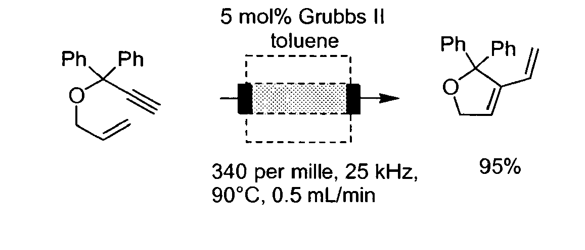
- Weiterhin wurde die Erwärmung von gerollter Kupferfolie durch elektromagnetische Induktion überprüft: Die Folie erwärmte sich bei einer Frequenz von 20 kHz und einem PWM von nur 175 ‰ nach weniger als 10 Minuten auf > 160 °C.
- Als Heizmedium für die nachstehenden Versuche wurde MagSilica® 58/85 der Firma Evonik (früher Degussa) eingesetzt, das gegebenenfalls gemäß nachstehen Verfahren oberflächlich modifiziert wurde.
- Bei der Herstellung der Katalysatoren wurden Schüttler verwendet, um eine Durchmischung der Substrate zu gewährleisten. Beim Waschen stellten sich herkömmliche Filterpapiere als ungeeignet heraus, da die Poren zu schnell verstopften. Daher wurde der Feststoff bei jedem Waschschritt zentrifugiert. Die Überprüfung der magnetischen Eigenschaften bzw. die magnetische Separation wurde mit einem handelsüblichen Magneten durchgeführt.
-

-

- MagSilica 50/85® (15.0 g) wird für 2 h in bidest. H2O (150 mL) am Rückfluss erhitzt und anschließend im Hochvakuum getrocknet. Der Feststoff wird in Toluol (180 mL) aufgeschlämmt und mit (p-Chlormethyl)phenyltrimethoxysilan (15 mL, 68.1 mmol) für 26 h geschüttelt. Die Reaktionsmischung wird für 3 h unter Rückfluss erhitzt. Nach dem Erkalten wird der Feststoff zentrifugiert und mit Toluol (2x 40 mL) gewaschen. Nach Trocknen im Hochvakuum werden 12.1 g von 14 als schwarzes, magnetisches Pulver erhalten.
-

- 14 (12.0 g) wird in einer mit Trimethylamin gesättigten Lösung von Toluol (350 mL) aufgeschlämmt und für 72 h geschüttelt. Der Feststoff wird zentrifugiert und mit Toluol (3x 40 mL) gewaschen und im Hochvakuum getrocknet. Es werden 12.4 g von 61 als schwarzes, magnetisches Pulver erhalten.
-

- 61 (3.0 g) wird in bidest. H2O (150 mL) aufgeschlämmt und mit einer Lösung von Natriumtetrachloropalladat (100 mg, 0.34 mmol) in bidest. H2O (10 mL) für 18 h geschüttelt. Der Feststoff wird zentrifugiert und mit bidest. H2O (2x 40 mL) gewaschen und im Hochvakuum getrocknet. Es werden 2.7 g von 15 als schwarzes, magnetisches Pulver erhalten.
-

- 15 (2.7 g) wird in bidest. H2O (30 mL) aufgeschlämmt und mit einer Lösung von Natriumborhydrid (0.64 g, 16.9 mmol) in bidest. H2O (15 mL) versehen. Die Reaktionsmischung wird für 5 h geschüttelt, zentrifugiert und mit bidest. H2O, ges. NaCl-Lösung und H2O gewaschen (jeweils 40 mL) und im Hochvakuum getrocknet. Es werden 2.6 g von 7 als schwarzes, magnetisches Pulver erhalten. Die Beladung des Katalysators beträgt 6.7 10-5 mmol Pd/mg Katalysator (ICP-MS Spurenanalyse).
-

-

- MagSilica 50/85® (6.0 g) wird für 6 h im Hochvakuum bei 200 °C getrocknet und anschließend unter Schutzgasatmosphäre in abs. Toluol (150 mL) aufgeschlämmt. Es wird 3-Aminopropyltrimethoxysilan (4.5 mL, 25.3 mmol) in abs. Toluol (10 mL) hinzugefügt. Die Reaktionsmischung wird für 16 h geschüttelt und zentrifugiert. Der Feststoff wird mit abs. Toluol (2x 40 mL) und wässrigem Toluol (1x 40 mL) gewaschen und anschließend im Hochvakuum getrocknet. Es werden 5.3 g von 12 als schwarzes, magnetisches Pulver erhalten.
-

- 12 (4.0 g) wird unter Schutzgasatmosphäre in abs. Diethylether (180 mL) aufgeschlämmt und mit HBF4·OEt2 (10 mL, 38.9 mmol) versehen. Die Reaktionsmischung wird für 2 h geschüttelt. Anschließend wird der Feststoff zentrifugiert und mit Diethylether, wässrigem Diethylether, ges. NaCl-Lösung und bidest. H2O (jeweils 40 mL) gewaschen und im Hochvakuum getrocknet. Es werden 3.5 g von 62 als schwarzes, magnetisches Pulver erhalten.
-

-

- 13 (2.5 g) wird in bidest. H2O (40 mL) aufgeschlämmt und mit einer Lösung von Natriumborhydrid (0.64 g, 16.9 mmol) in bidest. H2O (15 mL) versehen. Die Reaktionsmischung wird geschüttelt bis die Gasentwicklung aufhört. Der Feststoff wird mit bidest. H2O, gesättigter NaCl-Lösung und bidest. H2O gewaschen (jeweils 40 mL) und im Hochvakuum getrocknet. Es werden 2.3 g von 6 als schwarzes, magnetisches Pulver erhalten. Die Beladung des Katalysators beträgt 3.7 10-5 mmol Pd/mg Katalysator.
-

- MagSilica 50/85® (2.0 g) wird in EtOH aufgeschlämmt und mit einer Lösung von Palladiumnitratdihydrat (84 mg, 0.32 mmol) in EtOH (10 mL) bei 50 °C für 30 min gerührt. Die Reaktionsmischung wird im Vakuum bis zur Trockne eingeengt. Nach Trocknen im Vakuum werden 1.92 g von 8 als schwarzes, magnetisches Pulver erhalten. Die Beladung des Katalysators beträgt 11.3 . 10-5 mmol Pd/mg Katalysator.
-

-

- MagSilica 50/85® (3.0 g) wird für 2 h in bidest. H2O (50 mL) unter Rückfluss erhitzt und im Hochvakuum getrocknet. Der schwarze Feststoff wird in Dodecan (18 mL) mit DVB (0.41g, 5.3 m%), VBC (7.11 g, 94.7 m%) und AIBN (37.5 mg, 0.5 m%) versehen und mit einem KPG-Rührer bei 70 °C für 16 h gerührt. Die erhaltene schwarze Suspension wird in einem Soxlett-Extraktor für 13 h mit Chloroform gereinigt. Das Produkt wird mit einem Magneten von dem übrigen Polymer getrennt und im Hochvakuum getrocknet. Es werden 4.4 g von 63 als schwarz-grünliches, magnetisches Pulver erhalten.
-

- 63 (4.4 g) wird in einer mit Trimethylamin gesättigten Lösung von Toluol (350 mL) aufgeschlämmt und für 93 h geschüttelt. Der Feststoff wird zentrifugiert und mit Toluol (3x 40 mL) gewaschen. Nach Trocknen im Hochvakuum wird ein schwarz-grünliches, magnetisches Pulver erhalten. Es werden 4.1 g von 63 erhalten.
-

- 64 (4.1 g) wird in bidest. H2O (150 mL) aufgeschlämmt und mit einer Lösung von Natriumtetrachloropalladat (700 mg, 2.38 mmol) in bidest. H2O (10 mL) für 17 h geschüttelt. Der Feststoff wird zentrifugiert, mit bidest. H2O (3x 40 mL) gewaschen und im Hochvakuum getrocknet. Es wird ein schwarz-grünlicher, magnetischer Feststoff erhalten. Das Rohprodukt wird ohne Trocknung in der folgenden Reaktion eingesetzt.
-

- 65 (4.0 g) wird in bidest. H2O (50 mL) aufgeschlämmt und mit einer Lösung von Natriumborhydrid (0.5 g, 13.2 mmol) in bidest. H2O (15 mL) versehen. Die Reaktionsmischung wird für 2 h geschüttelt, zentrifugiert, mit bidest. H2O, gesättigter NaCl-Lösung und H2O gewaschen (jeweils 40 mL) und im Hochvakuum getrocknet. Es werden 3.3 g von 9 als schwarz-grünliches, magnetisches Pulver erhalten.
- Nachfolgend werden einige chemische Reaktionen angegeben, die mit dem erfindungsgemäßen Verfahren durchgeführt wurden. In allen Fällen wurde Dimethylformamid (DMF) als Lösungsmittel verwendet. Zum Vergleich wurden dieselben Reaktionen auch mit konventioneller Erwärmung in einem Heizbad mit denselben Temperaturen und Reaktionszeiten durchgeführt. In den Tabellen werden die Reaktionsausbeuten im Vergleich angegeben, wobei "thermisch" der Umsatz im Heizbad (Vergleich) und "induktiv" der Umsatz nach dem erfindungsgemäßen Verfahren bedeuten. Bei dem erfindungsgemäßen Verfahren wurde die Gesamt-Reaktionszeit dadurch erreicht, dass das Reaktionsmedium im Kreis geführt wurde und den Reaktor entsprechend oft durchströmte.
- Um bei dem erfindungsgemäßen Verfahren angenähert dieselbe Reaktionstemperatur wie bei dem thermischen Verfahren zu erreichen, wurden Vorversuche zum Aufheizverhalten durchgeführt. Hierzu wurde der Rohrreaktor mit einer Mischung aus MagSilica® und Sand (ca. 67 Vol-% MagSilica und 33 Vol-% Sand) und mit DMF durchströmt. Der Induktor wurde stets mit 25 kHz betrieben. Diese Bedingungen wurden auch bei den einzelnen Reaktionen eingehalten.
-
Tabelle 1: Heiztabelle. Messung jeweils bis zum Konstantbleiben der Temperatur mit 25 kHz, 2 mL/min in DMF PWM [‰] Messzeit [min] Außentemp. [°C]a Fluidtemp. [°C]b 600 2 > 170 -c 400 4 > 170 -c 350 10 > 170 72 325 15 145 60 300 15 136 49 250 15 71 37 225 15 54 20 200 15 33 19 , a Messung über Temperaturfühler, Messung über Infrarotthermometer, keine Messung wegen Fluidverdampfung möglich. -
Tabelle 2: Heck-Mizoroki-Kupplungen, 1 mmol Arylhalogenid, 3 Äq. Styrol, 3 Äq. n-Bu3N, 2.8 mol% Katalysator 7, Reaktionszeit jeweils 1 h, Flussrate 2 mL/min, PWM = 325 ‰. Reaktionsprinzip: 
Beisp. Nr. Arylhalogenid Alken Produkt Umsatz thermisch [%] Umsatz induktiv [%]a 1 
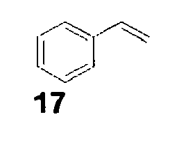

0 7.5 2 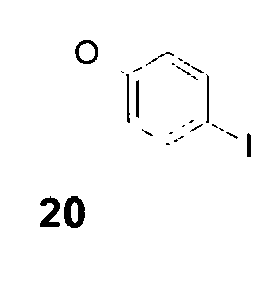


60.0 84.2 Tabelle 3: Weitere Katalysatoren; Suzuki-Miyaura-Reaktion 2 mL/min, Reaktionszeit jeweils 1h,: 0.5 mmol Arylhalogenid, 1.5 Äq. Boronsäure, 2.4 Äq. CsF, PWM = 750 ‰ a 1 mol%, b 2.8 mol%,. Suzuki-Miyaura-Reaktion: 
Katalysator Beisp. Nr. Umsatz Thermisch [%] Umsatz induktiv [%] Najera-Katalysator a 
3 23.0 49.1 5 % Pd/Aktivkohle a 4 5.8 58.8 Raschig-Ring-Katalysator a 
5 50.2 78.7 Katalysator 8 b 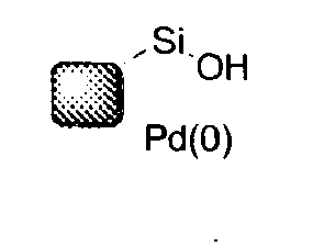
6 - 97.4 - Umesterung von Zimtsäureethylester 59 zu Zimtsäuremethylester 60. Dieser Versuch wurde in Anlehnung an eine Literaturvorschrift durchgeführt (K. Jansson, T. Fristedt, A. Olsson, B. Svensson, S. Jönsson, J. Org. Chem., 2006, 71, 1658-1667). Dabei wurde ein Überschuss an Natriummethanolat verwendet, um das Gleichgewicht der Umesterung zu dem gewünschten Produkt zu verschieben. Mit induktiver Heizung (Flussrate: 2 mL/min, PWM = 240 ‰) konnte nach 25 min 93 % Produkt isoliert werden.

- Weitere thermische Reaktionen im Durchfluss mit induktiver Beheizung
(Dabei bedeut: prom = PWM in ‰. Die Zahlen in % unter der Produktformel geben die Produktausbeute an.) -

-

-

-
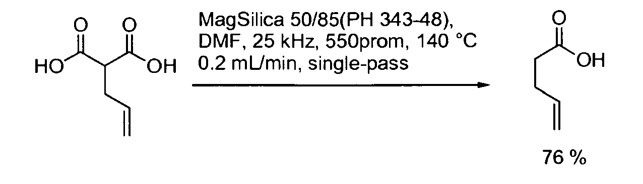
-
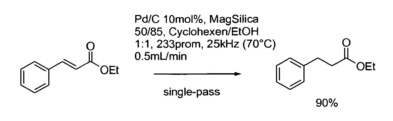
-
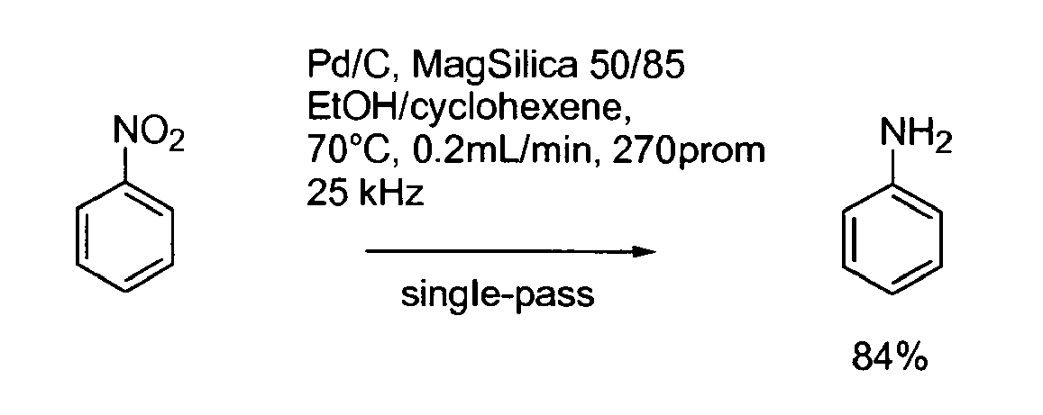
- Bei den Beispielen 12 und 13 wurde der Katalysator Pd/C (Palladium auf Aktivkohle) in Abmischung mit MagSilicaR eingesetzt. Als Reduktionsmittel (Wasserstoffquelle) dient im wesentlichen das Cyclohexen.
-

Claims (12)
- Verfahren zum Durchführen einer chemischen Reaktion zur Herstellung einer Zielverbindung durch Erwärmen eines Reaktionsmediums enthaltend mindestens einen ersten Reaktanten in einem Reaktor, wodurch eine chemische Bindung innerhalb des ersten Reaktanten oder zwischen dem ersten und einem zweiten Reaktanten gebildet oder verändert wird, wobei man das Reaktionsmedium in Kontakt mit einem durch elektromagnetische Induktion erwärmbaren festen Heizmedium bringt, das sich innerhalb des Reaktors befindet und das von dem Reaktionsmedium umgeben ist, und das Heizmedium durch elektromagnetische Induktion mit Hilfe eines Induktors erwärmt, wobei sich aus dem ersten Reaktanten oder aus dem ersten und einem zweiten Reaktanten die Zielverbindung bildet und wobei man die Zielverbindung von dem Heizmedium abtrennt, dadurch gekennzeichnet, dass das Reaktionsmedium im Reaktor als Flüssigkeit vorliegt und dass der Induktor ein Wechselfeld mit einer Frequenz im Bereich von 1 bis 100 kHz erzeugt.
- Verfahren nach Anspruch 1, dadurch gekennzeichnet, dass das Heizmedium ausgewählt ist aus Partikeln elektrisch leitfähiger und/oder magnetisierbarer Festkörper, wobei die Partikel eine mittlere Teilchengröße im Bereich von 1 bis 1000 nm haben.
- Verfahren nach Anspruch 2 , dadurch gekennzeichnet, dass das Heizmedium ausgewählt ist aus Partikeln magnetisierbarer Festkörper, wobei jedes Partikel mindestens einen Kern aus einem magnetisierbarem Material enthält, der von einem nicht magnetischen Material umhüllt ist.
- Verfahren nach einem der Ansprüche 2 und 3, dadurch gekennzeichnet, dass das Heizmedium ausgewählt ist aus Partikel magnetisierbaren Festkörper und dass diese in Mischung mit weiteren Partikeln vorliegen, die nicht durch elektromagnetische Induktion erwärmbar sind.
- Verfahren nach einem oder mehreren der Ansprüche 1 bis 4, dadurch gekennzeichnet, dass das feste Heizmedium oberflächlich mit einer für die chemische Reaktion katalytisch wirkenden Substanz belegt ist.
- Verfahren nach einem oder mehreren der Ansprüche 1 bis 5, dadurch gekennzeichnet, dass man die chemische Reaktion chargenweise durchführt, wobei man während der Reaktion das Reaktionsmedium und das feste Heizmedium relativ zueinander bewegt.
- Verfahren nach Anspruch 6, dadurch gekennzeichnet, dass sich das Reaktionsmedium zusammen mit Partikeln des Heizmediums in einem Reaktionsbehälter befindet und mit Hilfe eines im Reaktionsmedium befindlichen Bewegungselements.bewegt wird, wobei das Bewegungselement als Induktor eingerichtet ist, durch den die Partikel des Heizmediums erwärmt werden.
- Verfahren nach einem oder mehreren der Ansprüche 1 bis 5, dadurch gekennzeichnet, dass man die chemische Reaktion in einem Durchflussreaktor durchführt, der zumindest teilweise mit dem festen Heizmedium gefüllt ist und hierdurch mindestens eine durch elektromagnetische Induktion erwärmbare Heizzone aufweist, wobei das Reaktionsmedium den Durchflussreaktor durchströmt und wobei sich der Induktor außerhalb des Reaktors befindet.
- Verfahren nach Anspruch 8, dadurch gekennzeichnet, dass das Reaktionsmedium den Durchflussreaktor mit einer solchen Geschwindigkeit einmal oder mehrmals durchströmt, dass die gesamte Kontaktzeit des Reaktionsmediums mit dem Heizmedium im Bereich von einer Sekunde bis 2 Stunden liegt.
- Verfahren nach einem oder mehreren der Ansprüche 1 bis 9, dadurch gekennzeichnet, dass der Reaktor als Druckreaktor ausgelegt ist und die chemische Reaktion bei einem Druck von oberhalb Atmosphärendruck, vorzugsweise von mindestens 1,5 bar durchgeführt wird.
- Verfahren nach einem oder mehreren der Ansprüche 1 bis 10, dadurch gekennzeichnet, dass das Heizmedium ferromagnetisch ist und eine Curie-Temperatur im Bereich von 40 bis 250°C aufweist und so ausgewählt wird, dass sich die Curie-Temperatur um nicht mehr als 20°C, von der ausgewählten Reaktionstemperatur unterscheidet.
- Verfahren nach einem oder mehreren der Ansprüche 1 bis 11, dadurch gekennzeichnet, dass bei der chemischen Reaktion eine chemische Bindung zwischen zwei C-Atomen oder zwischen einem C-Atom und einem Atom X gebildet wird, wobei X ausgewählt ist aus: H, B, O, N, S, P, Si, Ge, Sn, Pb, As, Sb, Bi und Halogen.
Applications Claiming Priority (2)
| Application Number | Priority Date | Filing Date | Title |
|---|---|---|---|
| DE102007059967A DE102007059967A1 (de) | 2007-12-11 | 2007-12-11 | Verfahren zur Durchführung chemischer Reaktionen mit Hilfe eines induktiv erwärmten Heizmediums |
| PCT/EP2008/063763 WO2009074373A1 (de) | 2007-12-11 | 2008-10-14 | Verfahren zur durchführung chemischer reaktionen mit hilfe eines induktiv erwärmten heizmediums |
Publications (2)
| Publication Number | Publication Date |
|---|---|
| EP2219778A1 EP2219778A1 (de) | 2010-08-25 |
| EP2219778B1 true EP2219778B1 (de) | 2011-07-13 |
Family
ID=40383705
Family Applications (1)
| Application Number | Title | Priority Date | Filing Date |
|---|---|---|---|
| EP08859853A Not-in-force EP2219778B1 (de) | 2007-12-11 | 2008-10-14 | Verfahren zur durchführung chemischer reaktionen mit hilfe eines induktiv erwärmten heizmediums |
Country Status (9)
| Country | Link |
|---|---|
| US (2) | US20100249404A1 (de) |
| EP (1) | EP2219778B1 (de) |
| JP (1) | JP5587200B2 (de) |
| KR (1) | KR20100098387A (de) |
| CN (1) | CN101896263B (de) |
| AT (1) | ATE516077T1 (de) |
| DE (1) | DE102007059967A1 (de) |
| ES (1) | ES2367467T3 (de) |
| WO (1) | WO2009074373A1 (de) |
Families Citing this family (33)
| Publication number | Priority date | Publication date | Assignee | Title |
|---|---|---|---|---|
| DE102009027546A1 (de) | 2009-07-08 | 2011-01-13 | Henkel Ag & Co. Kgaa | Verfahren zur Umesterung mit Hilfe eines induktiv erwärmten Heizmediums |
| DE102009027545A1 (de) | 2009-07-08 | 2011-02-03 | Henkel Ag & Co. Kgaa | Verfahren zur Herstellung von Cyanacrylsäureestern in Gegenwart von Übergangsmetall-Katalysatoren |
| DE102009028856A1 (de) | 2009-08-25 | 2011-03-03 | Henkel Ag & Co. Kgaa | Verfahren zur präparativen Fragmentierung mit Hilfe eines induktiv erwärmteen Heizmediums |
| DE102009045636A1 (de) | 2009-10-13 | 2011-04-14 | Henkel Ag & Co. Kgaa | Verfahren zur Durchführung von sequentiellen Reaktionen mit Hilfe eines induktiv erwärmten Heizmediums |
| DE102009045861A1 (de) | 2009-10-20 | 2011-04-21 | Henkel Ag & Co. Kgaa | Verfahren zur Durchführung einer Phasenumwandlung |
| DE102009046131A1 (de) * | 2009-10-29 | 2011-05-05 | Henkel Ag & Co. Kgaa | Alternative Synthese von 1.1-substituierten Olefinen mit elektronenziehenden Substituenten |
| WO2011121623A1 (en) * | 2010-04-01 | 2011-10-06 | Giorgio Pecci | Apparatus for transforming long molecular chain organic matter |
| DE102010050152B4 (de) * | 2010-11-02 | 2016-02-11 | Adam Handerek | Reaktor und Verfahren zum zumindest teilweisen Zersetzen, insbesondere Depolymerisieren, und/oder Reinigen von Kunststoffmaterial |
| KR101364062B1 (ko) * | 2011-08-26 | 2014-02-21 | 재단법인 포항산업과학연구원 | 바이오 디젤의 제조 방법 |
| US10174223B2 (en) * | 2013-11-30 | 2019-01-08 | Hrl Laboratories, Llc | Formulations, methods, and apparatus for remote triggering of frontally cured polymers |
| CN104060236B (zh) * | 2014-05-14 | 2016-07-06 | 中国科学院广州能源研究所 | 一种片状基片的连续镀膜生产系统 |
| US10035124B2 (en) * | 2014-08-12 | 2018-07-31 | Empire Technology Development Llc | Methods, materials, and systems for converting alcohols |
| CN105600832A (zh) * | 2014-11-19 | 2016-05-25 | 正大天晴药业集团股份有限公司 | 一种经修饰的超顺磁性氧化铁的制备方法 |
| WO2017036794A1 (en) * | 2015-08-28 | 2017-03-09 | Haldor Topsøe A/S | Induction heating of endothermic reactions |
| WO2017072057A1 (en) | 2015-10-28 | 2017-05-04 | Haldor Topsøe A/S | Dehydrogenation of alkanes |
| JP7050695B2 (ja) * | 2016-04-26 | 2022-04-08 | ハルドール・トプサー・アクチエゼルスカベット | ニトリルの合成方法 |
| CN210045214U (zh) | 2016-04-26 | 2020-02-11 | 托普索公司 | 反应器系统 |
| WO2017186608A1 (en) * | 2016-04-26 | 2017-11-02 | Haldor Topsøe A/S | Ferromagnetic materials for induction heated catalysis |
| WO2017195107A2 (en) * | 2016-05-11 | 2017-11-16 | Basf Corporation | Catalyst composition comprising magnetic material adapted for inductive heating |
| US10207241B2 (en) * | 2016-11-29 | 2019-02-19 | Kontak LLC | Inductively heated microchannel reactor |
| US20180318802A1 (en) * | 2017-05-03 | 2018-11-08 | James Dorman | Catalytic reaction |
| US11555473B2 (en) | 2018-05-29 | 2023-01-17 | Kontak LLC | Dual bladder fuel tank |
| US11638331B2 (en) | 2018-05-29 | 2023-04-25 | Kontak LLC | Multi-frequency controllers for inductive heating and associated systems and methods |
| WO2020016209A1 (en) | 2018-07-16 | 2020-01-23 | Haldor Topsøe A/S | Thermolytic fragmentation of sugars using resistance heating |
| GB2582614A (en) * | 2019-03-28 | 2020-09-30 | Johnson Matthey Plc | An exhaust gas treatment system and the use thereof for the treatment of an exhaust gas |
| CN110064404A (zh) * | 2019-05-06 | 2019-07-30 | 东南大学 | 一种纤维素加氢磁性催化剂的制备及其应用方法 |
| WO2020254184A1 (en) * | 2019-06-20 | 2020-12-24 | Haldor Topsøe A/S | Ferromagnetic catalyst support for induction heated catalysis |
| CN112058192B (zh) * | 2020-09-04 | 2021-12-14 | 湖南大学 | 一种连续流微反应器、制作方法及应用 |
| US20230356198A1 (en) * | 2020-10-08 | 2023-11-09 | Basf Corporation | Catalyst Composition Comprising Ferrite-Based Magnetic Material Adapted for Inductive Heating |
| EP4384307A1 (de) * | 2021-08-10 | 2024-06-19 | Teknologian Tutkimuskeskus VTT OY | Verfahren und vorrichtung zur behandlung von rohmaterial und verwendung |
| CN116143573A (zh) * | 2022-12-12 | 2023-05-23 | 东南大学 | 一种利用交变磁场的磁性催化剂在液固反应中的应用 |
| CN116650980A (zh) * | 2023-05-15 | 2023-08-29 | 北京化工大学 | 一种电磁加热耦合超重力旋转床装置 |
| CN117263183A (zh) * | 2023-10-11 | 2023-12-22 | 北京化工大学 | 一种电感加热碳酸盐与氢气反应生成氧化物和一氧化碳的碳减排方法 |
Family Cites Families (20)
| Publication number | Priority date | Publication date | Assignee | Title |
|---|---|---|---|---|
| GB8724561D0 (en) * | 1987-10-20 | 1987-11-25 | Ici Plc | Production process |
| US5272216A (en) * | 1990-12-28 | 1993-12-21 | Westinghouse Electric Corp. | System and method for remotely heating a polymeric material to a selected temperature |
| DE69533582T2 (de) * | 1994-02-01 | 2005-11-17 | Invista Technologies S.A.R.L., Wilmington | Verfahren zur herstellung von wasserstoffcyanid |
| US6110239A (en) * | 1996-05-31 | 2000-08-29 | Marathon Ashland Petroleum Llc | Molten metal hydrocarbon gasification process |
| WO1999001212A1 (en) | 1997-07-03 | 1999-01-14 | E.I. Du Pont De Nemours And Company | Inductively heated catalytic reactor |
| DE19800294A1 (de) | 1998-01-07 | 1999-07-08 | Mueller Schulte Detlef Dr | Induktiv aufheizbare magnetische Polymerpartikel sowie Verfahren zur Herstellung und Verwendung derselben |
| WO2000038831A1 (en) | 1998-12-31 | 2000-07-06 | Hexablock, Inc. | Magneto absorbent |
| US6953656B2 (en) * | 2000-07-14 | 2005-10-11 | Massachusetts Institute Of Technology | Direct, externally imposed control of polypeptides |
| US6953659B2 (en) * | 2000-07-14 | 2005-10-11 | Massachusetts Institute Of Technology | Direct, externally imposed control of nucleic acids |
| DE10140089A1 (de) * | 2001-08-16 | 2003-02-27 | Degussa | Superparamagnetische oxidische Partikel, Verfahren zu deren Herstellung und ihre Verwendung |
| US7569624B2 (en) * | 2001-11-13 | 2009-08-04 | Degussa Ag | Curable bonded assemblies capable of being dissociated |
| DE10163399A1 (de) * | 2001-12-21 | 2003-07-10 | Sustech Gmbh & Co Kg | Nanopartikuläre Zubereitung |
| WO2003075368A2 (en) * | 2002-03-01 | 2003-09-12 | Board Of Control Of Michigan Technological University | Method and apparatus for induction heating of thin films |
| US7070743B2 (en) * | 2002-03-14 | 2006-07-04 | Invista North America S.A R.L. | Induction-heated reactors for gas phase catalyzed reactions |
| JP2004224595A (ja) * | 2003-01-20 | 2004-08-12 | Sekisui Chem Co Ltd | 水素貯蔵・供給装置 |
| JP2004250255A (ja) * | 2003-02-18 | 2004-09-09 | Sekisui Chem Co Ltd | 水素貯蔵・発生装置 |
| TWI326713B (en) | 2005-02-18 | 2010-07-01 | Nippon Steel Corp | Induction heating device for heating a traveling metal plate |
| JP4786365B2 (ja) * | 2005-02-18 | 2011-10-05 | 新日本製鐵株式会社 | 金属板の誘導加熱装置及び誘導加熱方法 |
| DE102005051637A1 (de) | 2005-10-26 | 2007-05-03 | Atotech Deutschland Gmbh | Reaktorsystem mit einem mikrostrukturierten Reaktor sowie Verfahren zur Durchführung einer chemischen Reaktion in einem solchen Reaktor |
| DE102006062651B4 (de) * | 2006-11-14 | 2009-12-31 | Helmholtz-Zentrum Für Umweltforschung Gmbh - Ufz | Verfahren und Vorrichtung zur thermo-chromatographischen Erwärmung von Feststoffbetten |
-
2007
- 2007-12-11 DE DE102007059967A patent/DE102007059967A1/de not_active Withdrawn
-
2008
- 2008-10-14 EP EP08859853A patent/EP2219778B1/de not_active Not-in-force
- 2008-10-14 AT AT08859853T patent/ATE516077T1/de active
- 2008-10-14 KR KR1020107012834A patent/KR20100098387A/ko not_active Ceased
- 2008-10-14 JP JP2010537343A patent/JP5587200B2/ja not_active Expired - Fee Related
- 2008-10-14 CN CN200880120064.8A patent/CN101896263B/zh not_active Expired - Fee Related
- 2008-10-14 ES ES08859853T patent/ES2367467T3/es active Active
- 2008-10-14 WO PCT/EP2008/063763 patent/WO2009074373A1/de not_active Ceased
-
2010
- 2010-06-11 US US12/813,653 patent/US20100249404A1/en not_active Abandoned
-
2012
- 2012-04-16 US US13/447,498 patent/US8871964B2/en not_active Expired - Fee Related
Also Published As
| Publication number | Publication date |
|---|---|
| WO2009074373A1 (de) | 2009-06-18 |
| US8871964B2 (en) | 2014-10-28 |
| CN101896263A (zh) | 2010-11-24 |
| JP2011506072A (ja) | 2011-03-03 |
| US20100249404A1 (en) | 2010-09-30 |
| EP2219778A1 (de) | 2010-08-25 |
| KR20100098387A (ko) | 2010-09-06 |
| ATE516077T1 (de) | 2011-07-15 |
| US20120202994A1 (en) | 2012-08-09 |
| JP5587200B2 (ja) | 2014-09-10 |
| DE102007059967A1 (de) | 2009-06-18 |
| ES2367467T3 (es) | 2011-11-03 |
| CN101896263B (zh) | 2014-09-03 |
Similar Documents
| Publication | Publication Date | Title |
|---|---|---|
| EP2219778B1 (de) | Verfahren zur durchführung chemischer reaktionen mit hilfe eines induktiv erwärmten heizmediums | |
| EP2396109A1 (de) | Verfahren zur durchführung von oxidationsreaktionen mit hilfe eines induktiv erwärmten heizmediums | |
| EP2470623A2 (de) | Verfahren zur präparativen fragmentierung mit hilfe eines induktiv erwärmten heizmediums | |
| EP2451772B1 (de) | Verfahren zur herstellung von cyanacrylsäureestern in gegenwart von übergangsmetall-katalysatoren | |
| Hameed Mahmood et al. | Magnetic nanoparticles supported copper nanocomposite: a highly active nanocatalyst for synthesis of benzothiazoles and polyhydroquinolines | |
| EP3160633B1 (de) | Verfahren zur selbstregulation eines systems | |
| Esmaeilpour et al. | Preparation and characterization of Fe3O4@ SiO2@ PMA: AS an efficient and recyclable nanocatalyst for the synthesis of 1-amidoalkyl-2-naphthols | |
| Moradnia et al. | Green synthesis and characterization of NiFe2O4@ ZnMn2O4 magnetic nanocomposites: An efficient and reusable spinel nanocatalyst for the synthesis of tetrahydropyrimidine and polyhydroquinoline derivatives under microwave irradiation | |
| Safari et al. | Sulphamic acid-functionalized magnetic Fe3O4 nanoparticles as recyclable catalyst for synthesis of imidazoles under microwave irradiation | |
| Safari et al. | A highly effective synthesis of pyrimido [4, 5-b] quinoline-tetraones using H3PW12O40/chitosan/NiCo2O4 as a novel magnetic nanocomposite | |
| DE102009045636A1 (de) | Verfahren zur Durchführung von sequentiellen Reaktionen mit Hilfe eines induktiv erwärmten Heizmediums | |
| DE102009042523A1 (de) | Vorrichtung zur kontinuierlichen Durchführung heterogen katalysierter chemischer Reaktionen bei hohen Temperaturen | |
| Atarod et al. | A facile green synthesis of MgCoFe2O4 nanomaterials with robust catalytic performance in the synthesis of pyrano [2, 3-d] pyrimidinedione and their bis-derivatives | |
| Li et al. | Tailoring a magnetically separable NiFe2O4 nanoparticle catalyst for Knoevenagel condensation | |
| DE102005049136A1 (de) | Zubereitung, enthaltend ein polymerisierbares Monomer und/oder ein Polymer und darin dispergiert ein superparamagnetisches Pulver | |
| Shaikh et al. | Bimetallic CoCeO2 oxide nanoparticles: An efficient and reusable heterogeneous catalyst for the preparation of 2‐amino‐3‐cyano‐4 H‐pyran derivatives | |
| Yuan et al. | Preparation of a novel, efficient, and recyclable magnetic catalyst, Cu (II)-OHPC-Fe3O4 nanoparticles, and a solvent-free protocol for the synthesis of coumarin derivatives | |
| Eftekhari-Sis et al. | Pyridylmethylaminoacetic acid functionalized Fe3O4 magnetic nanorods as an efficient catalyst for the synthesis of 2-aminochromene and 2-aminopyran derivatives | |
| Cahyana et al. | Utilization of environmentally friendly catalyst Fe3O4 from iron rust in the synthesis of spiropiperidine derivative | |
| Shahbazarab et al. | Fe 3 O 4@ RHA@ TiO 2: preparation, characterization, and application in the nanocatalytic synthesis of tetrahydrobenzo [b] pyrans | |
| DE102009027546A1 (de) | Verfahren zur Umesterung mit Hilfe eines induktiv erwärmten Heizmediums | |
| Baminejhad et al. | Synthesis of cobalt-ferrite and zinc oxide metal nanoparticles based-bentonite using SDS and their investigation as catalysts in synthesis of benzylbarbiturocoumarins | |
| Taheri et al. | Synthesis of benzo [a] furo [2, 3-c] phenazine derivatives via microwave irradiation by catalyzed Fe3O4@ MCM-48@ IL/Pd for high-performance removal of rhodamine B and determination of losartan using modified glassy carbon electrode | |
| Bibave et al. | Synthesis and Characterization of CuFe2O4@ Xanthan gum@ SO3H Nanoparticles: A New Heterogeneous Magnetically Separable Catalyst for the One-Pot Solvent-Free Synthesis of Imidazoles | |
| Gaikwad | DABCO entrapped in agar-agar: A heterogeneous gelly catalyst for multi-component synthesis of 2-Amino-4H-Chromenes |
Legal Events
| Date | Code | Title | Description |
|---|---|---|---|
| PUAI | Public reference made under article 153(3) epc to a published international application that has entered the european phase |
Free format text: ORIGINAL CODE: 0009012 |
|
| 17P | Request for examination filed |
Effective date: 20100511 |
|
| AK | Designated contracting states |
Kind code of ref document: A1 Designated state(s): AT BE BG CH CY CZ DE DK EE ES FI FR GB GR HR HU IE IS IT LI LT LU LV MC MT NL NO PL PT RO SE SI SK TR |
|
| AX | Request for extension of the european patent |
Extension state: AL BA MK RS |
|
| GRAP | Despatch of communication of intention to grant a patent |
Free format text: ORIGINAL CODE: EPIDOSNIGR1 |
|
| DAX | Request for extension of the european patent (deleted) | ||
| GRAS | Grant fee paid |
Free format text: ORIGINAL CODE: EPIDOSNIGR3 |
|
| GRAA | (expected) grant |
Free format text: ORIGINAL CODE: 0009210 |
|
| AK | Designated contracting states |
Kind code of ref document: B1 Designated state(s): AT BE BG CH CY CZ DE DK EE ES FI FR GB GR HR HU IE IS IT LI LT LU LV MC MT NL NO PL PT RO SE SI SK TR |
|
| REG | Reference to a national code |
Ref country code: GB Ref legal event code: FG4D Free format text: NOT ENGLISH |
|
| REG | Reference to a national code |
Ref country code: CH Ref legal event code: EP |
|
| REG | Reference to a national code |
Ref country code: IE Ref legal event code: FG4D Free format text: LANGUAGE OF EP DOCUMENT: GERMAN |
|
| REG | Reference to a national code |
Ref country code: DE Ref legal event code: R096 Ref document number: 502008004218 Country of ref document: DE Effective date: 20110908 |
|
| REG | Reference to a national code |
Ref country code: NL Ref legal event code: VDEP Effective date: 20110713 |
|
| REG | Reference to a national code |
Ref country code: ES Ref legal event code: FG2A Ref document number: 2367467 Country of ref document: ES Kind code of ref document: T3 Effective date: 20111103 |
|
| PG25 | Lapsed in a contracting state [announced via postgrant information from national office to epo] |
Ref country code: HR Free format text: LAPSE BECAUSE OF FAILURE TO SUBMIT A TRANSLATION OF THE DESCRIPTION OR TO PAY THE FEE WITHIN THE PRESCRIBED TIME-LIMIT Effective date: 20110713 Ref country code: IS Free format text: LAPSE BECAUSE OF FAILURE TO SUBMIT A TRANSLATION OF THE DESCRIPTION OR TO PAY THE FEE WITHIN THE PRESCRIBED TIME-LIMIT Effective date: 20111113 Ref country code: LT Free format text: LAPSE BECAUSE OF FAILURE TO SUBMIT A TRANSLATION OF THE DESCRIPTION OR TO PAY THE FEE WITHIN THE PRESCRIBED TIME-LIMIT Effective date: 20110713 Ref country code: PT Free format text: LAPSE BECAUSE OF FAILURE TO SUBMIT A TRANSLATION OF THE DESCRIPTION OR TO PAY THE FEE WITHIN THE PRESCRIBED TIME-LIMIT Effective date: 20111114 Ref country code: FI Free format text: LAPSE BECAUSE OF FAILURE TO SUBMIT A TRANSLATION OF THE DESCRIPTION OR TO PAY THE FEE WITHIN THE PRESCRIBED TIME-LIMIT Effective date: 20110713 Ref country code: NL Free format text: LAPSE BECAUSE OF FAILURE TO SUBMIT A TRANSLATION OF THE DESCRIPTION OR TO PAY THE FEE WITHIN THE PRESCRIBED TIME-LIMIT Effective date: 20110713 Ref country code: SE Free format text: LAPSE BECAUSE OF FAILURE TO SUBMIT A TRANSLATION OF THE DESCRIPTION OR TO PAY THE FEE WITHIN THE PRESCRIBED TIME-LIMIT Effective date: 20110713 Ref country code: NO Free format text: LAPSE BECAUSE OF FAILURE TO SUBMIT A TRANSLATION OF THE DESCRIPTION OR TO PAY THE FEE WITHIN THE PRESCRIBED TIME-LIMIT Effective date: 20111013 |
|
| REG | Reference to a national code |
Ref country code: IE Ref legal event code: FD4D |
|
| PG25 | Lapsed in a contracting state [announced via postgrant information from national office to epo] |
Ref country code: LV Free format text: LAPSE BECAUSE OF FAILURE TO SUBMIT A TRANSLATION OF THE DESCRIPTION OR TO PAY THE FEE WITHIN THE PRESCRIBED TIME-LIMIT Effective date: 20110713 Ref country code: CY Free format text: LAPSE BECAUSE OF FAILURE TO SUBMIT A TRANSLATION OF THE DESCRIPTION OR TO PAY THE FEE WITHIN THE PRESCRIBED TIME-LIMIT Effective date: 20110713 Ref country code: PL Free format text: LAPSE BECAUSE OF FAILURE TO SUBMIT A TRANSLATION OF THE DESCRIPTION OR TO PAY THE FEE WITHIN THE PRESCRIBED TIME-LIMIT Effective date: 20110713 Ref country code: GR Free format text: LAPSE BECAUSE OF FAILURE TO SUBMIT A TRANSLATION OF THE DESCRIPTION OR TO PAY THE FEE WITHIN THE PRESCRIBED TIME-LIMIT Effective date: 20111014 Ref country code: SI Free format text: LAPSE BECAUSE OF FAILURE TO SUBMIT A TRANSLATION OF THE DESCRIPTION OR TO PAY THE FEE WITHIN THE PRESCRIBED TIME-LIMIT Effective date: 20110713 |
|
| BERE | Be: lapsed |
Owner name: HENKEL A.G. & CO. KGAA Effective date: 20111031 |
|
| PG25 | Lapsed in a contracting state [announced via postgrant information from national office to epo] |
Ref country code: CZ Free format text: LAPSE BECAUSE OF FAILURE TO SUBMIT A TRANSLATION OF THE DESCRIPTION OR TO PAY THE FEE WITHIN THE PRESCRIBED TIME-LIMIT Effective date: 20110713 Ref country code: SK Free format text: LAPSE BECAUSE OF FAILURE TO SUBMIT A TRANSLATION OF THE DESCRIPTION OR TO PAY THE FEE WITHIN THE PRESCRIBED TIME-LIMIT Effective date: 20110713 Ref country code: IE Free format text: LAPSE BECAUSE OF FAILURE TO SUBMIT A TRANSLATION OF THE DESCRIPTION OR TO PAY THE FEE WITHIN THE PRESCRIBED TIME-LIMIT Effective date: 20110713 |
|
| PLBE | No opposition filed within time limit |
Free format text: ORIGINAL CODE: 0009261 |
|
| STAA | Information on the status of an ep patent application or granted ep patent |
Free format text: STATUS: NO OPPOSITION FILED WITHIN TIME LIMIT |
|
| PG25 | Lapsed in a contracting state [announced via postgrant information from national office to epo] |
Ref country code: EE Free format text: LAPSE BECAUSE OF FAILURE TO SUBMIT A TRANSLATION OF THE DESCRIPTION OR TO PAY THE FEE WITHIN THE PRESCRIBED TIME-LIMIT Effective date: 20110713 Ref country code: RO Free format text: LAPSE BECAUSE OF FAILURE TO SUBMIT A TRANSLATION OF THE DESCRIPTION OR TO PAY THE FEE WITHIN THE PRESCRIBED TIME-LIMIT Effective date: 20110713 Ref country code: MC Free format text: LAPSE BECAUSE OF NON-PAYMENT OF DUE FEES Effective date: 20111031 |
|
| 26N | No opposition filed |
Effective date: 20120416 |
|
| PG25 | Lapsed in a contracting state [announced via postgrant information from national office to epo] |
Ref country code: DK Free format text: LAPSE BECAUSE OF FAILURE TO SUBMIT A TRANSLATION OF THE DESCRIPTION OR TO PAY THE FEE WITHIN THE PRESCRIBED TIME-LIMIT Effective date: 20110713 |
|
| PG25 | Lapsed in a contracting state [announced via postgrant information from national office to epo] |
Ref country code: BE Free format text: LAPSE BECAUSE OF NON-PAYMENT OF DUE FEES Effective date: 20111031 |
|
| REG | Reference to a national code |
Ref country code: DE Ref legal event code: R097 Ref document number: 502008004218 Country of ref document: DE Effective date: 20120416 |
|
| PG25 | Lapsed in a contracting state [announced via postgrant information from national office to epo] |
Ref country code: MT Free format text: LAPSE BECAUSE OF FAILURE TO SUBMIT A TRANSLATION OF THE DESCRIPTION OR TO PAY THE FEE WITHIN THE PRESCRIBED TIME-LIMIT Effective date: 20110713 |
|
| PG25 | Lapsed in a contracting state [announced via postgrant information from national office to epo] |
Ref country code: LU Free format text: LAPSE BECAUSE OF NON-PAYMENT OF DUE FEES Effective date: 20111014 |
|
| PG25 | Lapsed in a contracting state [announced via postgrant information from national office to epo] |
Ref country code: BG Free format text: LAPSE BECAUSE OF FAILURE TO SUBMIT A TRANSLATION OF THE DESCRIPTION OR TO PAY THE FEE WITHIN THE PRESCRIBED TIME-LIMIT Effective date: 20111013 |
|
| PG25 | Lapsed in a contracting state [announced via postgrant information from national office to epo] |
Ref country code: TR Free format text: LAPSE BECAUSE OF FAILURE TO SUBMIT A TRANSLATION OF THE DESCRIPTION OR TO PAY THE FEE WITHIN THE PRESCRIBED TIME-LIMIT Effective date: 20110713 |
|
| PG25 | Lapsed in a contracting state [announced via postgrant information from national office to epo] |
Ref country code: HU Free format text: LAPSE BECAUSE OF FAILURE TO SUBMIT A TRANSLATION OF THE DESCRIPTION OR TO PAY THE FEE WITHIN THE PRESCRIBED TIME-LIMIT Effective date: 20110713 |
|
| REG | Reference to a national code |
Ref country code: AT Ref legal event code: MM01 Ref document number: 516077 Country of ref document: AT Kind code of ref document: T Effective date: 20131014 |
|
| PG25 | Lapsed in a contracting state [announced via postgrant information from national office to epo] |
Ref country code: AT Free format text: LAPSE BECAUSE OF NON-PAYMENT OF DUE FEES Effective date: 20131014 |
|
| REG | Reference to a national code |
Ref country code: FR Ref legal event code: PLFP Year of fee payment: 8 |
|
| REG | Reference to a national code |
Ref country code: FR Ref legal event code: PLFP Year of fee payment: 9 |
|
| REG | Reference to a national code |
Ref country code: FR Ref legal event code: PLFP Year of fee payment: 10 |
|
| REG | Reference to a national code |
Ref country code: FR Ref legal event code: PLFP Year of fee payment: 11 |
|
| PGFP | Annual fee paid to national office [announced via postgrant information from national office to epo] |
Ref country code: DE Payment date: 20191021 Year of fee payment: 12 |
|
| PGFP | Annual fee paid to national office [announced via postgrant information from national office to epo] |
Ref country code: IT Payment date: 20191028 Year of fee payment: 12 Ref country code: FR Payment date: 20191028 Year of fee payment: 12 |
|
| PGFP | Annual fee paid to national office [announced via postgrant information from national office to epo] |
Ref country code: CH Payment date: 20191021 Year of fee payment: 12 |
|
| PGFP | Annual fee paid to national office [announced via postgrant information from national office to epo] |
Ref country code: ES Payment date: 20191122 Year of fee payment: 12 Ref country code: GB Payment date: 20191021 Year of fee payment: 12 |
|
| REG | Reference to a national code |
Ref country code: DE Ref legal event code: R119 Ref document number: 502008004218 Country of ref document: DE |
|
| REG | Reference to a national code |
Ref country code: CH Ref legal event code: PL |
|
| GBPC | Gb: european patent ceased through non-payment of renewal fee |
Effective date: 20201014 |
|
| PG25 | Lapsed in a contracting state [announced via postgrant information from national office to epo] |
Ref country code: DE Free format text: LAPSE BECAUSE OF NON-PAYMENT OF DUE FEES Effective date: 20210501 Ref country code: FR Free format text: LAPSE BECAUSE OF NON-PAYMENT OF DUE FEES Effective date: 20201031 |
|
| PG25 | Lapsed in a contracting state [announced via postgrant information from national office to epo] |
Ref country code: CH Free format text: LAPSE BECAUSE OF NON-PAYMENT OF DUE FEES Effective date: 20201031 Ref country code: LI Free format text: LAPSE BECAUSE OF NON-PAYMENT OF DUE FEES Effective date: 20201031 Ref country code: GB Free format text: LAPSE BECAUSE OF NON-PAYMENT OF DUE FEES Effective date: 20201014 |
|
| PG25 | Lapsed in a contracting state [announced via postgrant information from national office to epo] |
Ref country code: IT Free format text: LAPSE BECAUSE OF NON-PAYMENT OF DUE FEES Effective date: 20201014 |
|
| REG | Reference to a national code |
Ref country code: ES Ref legal event code: FD2A Effective date: 20220121 |
|
| PG25 | Lapsed in a contracting state [announced via postgrant information from national office to epo] |
Ref country code: ES Free format text: LAPSE BECAUSE OF NON-PAYMENT OF DUE FEES Effective date: 20201015 |