EP2218369B1 - Beverage brewing unit - Google Patents
Beverage brewing unit Download PDFInfo
- Publication number
- EP2218369B1 EP2218369B1 EP10161815.5A EP10161815A EP2218369B1 EP 2218369 B1 EP2218369 B1 EP 2218369B1 EP 10161815 A EP10161815 A EP 10161815A EP 2218369 B1 EP2218369 B1 EP 2218369B1
- Authority
- EP
- European Patent Office
- Prior art keywords
- capsule
- assembly
- brewing unit
- beverage
- passage
- Prior art date
- Legal status (The legal status is an assumption and is not a legal conclusion. Google has not performed a legal analysis and makes no representation as to the accuracy of the status listed.)
- Active
Links
- 235000013361 beverage Nutrition 0.000 title claims description 60
- 239000002775 capsule Substances 0.000 claims description 193
- XLYOFNOQVPJJNP-UHFFFAOYSA-N water Substances O XLYOFNOQVPJJNP-UHFFFAOYSA-N 0.000 claims description 48
- 238000002347 injection Methods 0.000 claims description 41
- 239000007924 injection Substances 0.000 claims description 41
- 239000004615 ingredient Substances 0.000 claims description 17
- 238000003780 insertion Methods 0.000 claims description 16
- 230000037431 insertion Effects 0.000 claims description 16
- 230000000712 assembly Effects 0.000 claims description 15
- 238000000429 assembly Methods 0.000 claims description 15
- 230000005484 gravity Effects 0.000 claims description 5
- 239000011888 foil Substances 0.000 claims description 4
- 238000013519 translation Methods 0.000 claims description 4
- 238000006073 displacement reaction Methods 0.000 claims description 2
- 235000013353 coffee beverage Nutrition 0.000 description 13
- 238000000605 extraction Methods 0.000 description 10
- 239000012528 membrane Substances 0.000 description 7
- 239000012530 fluid Substances 0.000 description 6
- 238000001802 infusion Methods 0.000 description 6
- 230000007246 mechanism Effects 0.000 description 5
- 239000007788 liquid Substances 0.000 description 4
- 238000007789 sealing Methods 0.000 description 4
- 230000008901 benefit Effects 0.000 description 3
- 238000013461 design Methods 0.000 description 3
- 230000009471 action Effects 0.000 description 2
- 230000000694 effects Effects 0.000 description 2
- 235000012041 food component Nutrition 0.000 description 2
- 239000005417 food ingredient Substances 0.000 description 2
- 230000000717 retained effect Effects 0.000 description 2
- 230000003068 static effect Effects 0.000 description 2
- XAGFODPZIPBFFR-UHFFFAOYSA-N aluminium Chemical compound [Al] XAGFODPZIPBFFR-UHFFFAOYSA-N 0.000 description 1
- 229910052782 aluminium Inorganic materials 0.000 description 1
- 239000004411 aluminium Substances 0.000 description 1
- 230000000903 blocking effect Effects 0.000 description 1
- 238000013124 brewing process Methods 0.000 description 1
- 230000008859 change Effects 0.000 description 1
- 238000004140 cleaning Methods 0.000 description 1
- 230000003111 delayed effect Effects 0.000 description 1
- 230000001419 dependent effect Effects 0.000 description 1
- 235000015114 espresso Nutrition 0.000 description 1
- 239000006260 foam Substances 0.000 description 1
- 235000013305 food Nutrition 0.000 description 1
- 210000002425 internal capsule Anatomy 0.000 description 1
- 238000004519 manufacturing process Methods 0.000 description 1
- 239000000463 material Substances 0.000 description 1
- 230000035515 penetration Effects 0.000 description 1
- 238000003466 welding Methods 0.000 description 1
Images


Classifications
-
- A—HUMAN NECESSITIES
- A47—FURNITURE; DOMESTIC ARTICLES OR APPLIANCES; COFFEE MILLS; SPICE MILLS; SUCTION CLEANERS IN GENERAL
- A47J—KITCHEN EQUIPMENT; COFFEE MILLS; SPICE MILLS; APPARATUS FOR MAKING BEVERAGES
- A47J31/00—Apparatus for making beverages
- A47J31/40—Beverage-making apparatus with dispensing means for adding a measured quantity of ingredients, e.g. coffee, water, sugar, cocoa, milk, tea
- A47J31/407—Beverage-making apparatus with dispensing means for adding a measured quantity of ingredients, e.g. coffee, water, sugar, cocoa, milk, tea with ingredient-containing cartridges; Cartridge-perforating means
-
- A—HUMAN NECESSITIES
- A47—FURNITURE; DOMESTIC ARTICLES OR APPLIANCES; COFFEE MILLS; SPICE MILLS; SUCTION CLEANERS IN GENERAL
- A47J—KITCHEN EQUIPMENT; COFFEE MILLS; SPICE MILLS; APPARATUS FOR MAKING BEVERAGES
- A47J31/00—Apparatus for making beverages
- A47J31/24—Coffee-making apparatus in which hot water is passed through the filter under pressure, i.e. in which the coffee grounds are extracted under pressure
- A47J31/34—Coffee-making apparatus in which hot water is passed through the filter under pressure, i.e. in which the coffee grounds are extracted under pressure with hot water under liquid pressure
- A47J31/36—Coffee-making apparatus in which hot water is passed through the filter under pressure, i.e. in which the coffee grounds are extracted under pressure with hot water under liquid pressure with mechanical pressure-producing means
- A47J31/3604—Coffee-making apparatus in which hot water is passed through the filter under pressure, i.e. in which the coffee grounds are extracted under pressure with hot water under liquid pressure with mechanical pressure-producing means with a mechanism arranged to move the brewing chamber between loading, infusing and ejecting stations
- A47J31/3623—Cartridges being employed
- A47J31/3628—Perforating means therefor
-
- A—HUMAN NECESSITIES
- A47—FURNITURE; DOMESTIC ARTICLES OR APPLIANCES; COFFEE MILLS; SPICE MILLS; SUCTION CLEANERS IN GENERAL
- A47J—KITCHEN EQUIPMENT; COFFEE MILLS; SPICE MILLS; APPARATUS FOR MAKING BEVERAGES
- A47J31/00—Apparatus for making beverages
- A47J31/24—Coffee-making apparatus in which hot water is passed through the filter under pressure, i.e. in which the coffee grounds are extracted under pressure
- A47J31/34—Coffee-making apparatus in which hot water is passed through the filter under pressure, i.e. in which the coffee grounds are extracted under pressure with hot water under liquid pressure
- A47J31/36—Coffee-making apparatus in which hot water is passed through the filter under pressure, i.e. in which the coffee grounds are extracted under pressure with hot water under liquid pressure with mechanical pressure-producing means
- A47J31/3604—Coffee-making apparatus in which hot water is passed through the filter under pressure, i.e. in which the coffee grounds are extracted under pressure with hot water under liquid pressure with mechanical pressure-producing means with a mechanism arranged to move the brewing chamber between loading, infusing and ejecting stations
- A47J31/3623—Cartridges being employed
- A47J31/3633—Means to perform transfer from a loading position to an infusing position
-
- A—HUMAN NECESSITIES
- A47—FURNITURE; DOMESTIC ARTICLES OR APPLIANCES; COFFEE MILLS; SPICE MILLS; SUCTION CLEANERS IN GENERAL
- A47J—KITCHEN EQUIPMENT; COFFEE MILLS; SPICE MILLS; APPARATUS FOR MAKING BEVERAGES
- A47J31/00—Apparatus for making beverages
- A47J31/24—Coffee-making apparatus in which hot water is passed through the filter under pressure, i.e. in which the coffee grounds are extracted under pressure
- A47J31/34—Coffee-making apparatus in which hot water is passed through the filter under pressure, i.e. in which the coffee grounds are extracted under pressure with hot water under liquid pressure
- A47J31/36—Coffee-making apparatus in which hot water is passed through the filter under pressure, i.e. in which the coffee grounds are extracted under pressure with hot water under liquid pressure with mechanical pressure-producing means
- A47J31/3666—Coffee-making apparatus in which hot water is passed through the filter under pressure, i.e. in which the coffee grounds are extracted under pressure with hot water under liquid pressure with mechanical pressure-producing means whereby the loading of the brewing chamber with the brewing material is performed by the user
- A47J31/3676—Cartridges being employed
- A47J31/369—Impermeable cartridges being employed
Definitions
- the present invention relates to a beverage brewing unit using capsules that contain a food ingredient for preparing a beverage or like food.
- the brewing unit is of simpler conception and of lower cost compared to existing brewing units.
- the capsule usually has to be positioned by the user on a capsule support or in a housing, then the device is closed manually or automatically around the capsule.
- patent application WO 98/47418 relates to a device for the extraction of premeasured inserts in which the inserts are inserted vertically and are extracted horizontally.
- the disadvantage of this device is that it comprises two movable parts for the extraction, which makes the mechanical principle more complicated.
- WO 2005/004683 relates to a capsule brewing device comprising: a first part; a second part that can be moved relative to the first part; a housing for the capsule and defining, in a closed position of the movable part against the fixed part, an extraction position of the capsule along an axis in said housing; an insertion and positioning part comprising means for guiding the capsule arranged so as to insert the capsule by gravity and position said capsule in an intermediate position; a drink pouring system; and the second movable part is so arranged and constructed to move the capsule from the intermediate position into the extraction position when the device is closed.
- EP 1 721 553 discloses a brewing unit for coffee machines using capsules.
- the unit has a front part with a beverage outlet and a rear part with a hot water inlet.
- the front part and the rear part are mounted in-between a pair of facing shoulder guide members.
- the front part is movable in-between these guide members to be urged against the rear part so as to form with the rear part a brewing chamber for accommodating a capsule to be extracted, whereby an unoccupied volume is left in front of the front member between the guide members within the machine.
- EP 1 659 547 relates to a beverage machine for making infusions, in particular, espresso coffee.
- the machine includes an infusion chamber within a brewing unit that has a movable front part with a return spring and a beverage outlet duct that extends through the assembly's outer housing.
- the movable front part cooperates with a rear part that is movable within the housing and that can be pushed against the movable front part to compress the return spring whereby the outlet duct slides through the assembly's outer housing.
- the pod is passed through the external housing to the infusion chamber via a rigid pod feed channel and then the pod is transferred into the infusion chamber by an external bushing on the movable rear part of the brewing unit which is provided with a cam-like path for moving the rear part.
- the pod must be moved during the closure of the brewing chamber and this can cause blocking and it also makes the retaining means of the pod more complex.
- opening and closing the brewing chamber involves simultaneously a linear displacement of the movable rear part within the housing, of the movable front part within the housing and of the outlet duct through the housing which increases the risk of hyper-guiding and jamming or improper alignment of the various parts that linearly move one relative to another.
- the fluid system comprises a moving assembly which makes the fluid system more complex to assemble. When upon extraction brewing unit is re-opened for removing the pod, pressurized water contained within the infusion chamber may project outside the hosing. Furthermore, an unoccupied volume is left within the machine between the front member and the casing when the outlet duct is in its retracted position.
- US 3,260,190 and WO 2005/072574 disclose a coffee machine having a removable drawer for positioning a coffee can therein.
- the drawer can be slid horizontally into the coffee machine and lifted towards a water injection arrangement.
- WO 2006/023309 discloses a coffee machine with a slidable drawer for the introduction of a coffee cartridge into the machine.
- the drawer is movable between an open and a closed position and has two cartridge half-shells that are pivotable against each other to form a brewing chamber when the drawer is in the closed position and pivotable apart when the drawer is slid out from the machine.
- US 6,966,251 discloses a coffee machine having a horizontally slidable drawer for positioning a capsule therein.
- EP 1 566 126 discloses a coffee machine with a vertical brewing unit for accommodating coffee pods.
- the brewing unit has a fixed upper part and a movable lower part for holding a pod and that can be pulled up for closing the brewing unit and let down for inserting or removing a pod.
- One aspect which is not part of the present invention relates to a beverage machine having an outermost casing and a brewing unit that comprises a first assembly and a second assembly cooperating together. Each assembly delimits part of a brewing chamber for containing an ingredient capsule. At least one of these assemblies is: movable away from the cooperating assembly into an open position within this beverage machine for forming between these assemblies a passage for inserting into and/or removing from the brewing unit an ingredient capsule; and movable to the cooperating assembly into a closed position for forming the brewing chamber.
- One of these assemblies is movable along a straight direction from the closed position to the open position and vice versa. In particular, this assembly is movable along a straight direction in translation or helicoidally.
- this assembly is movable outwards from the outermost casing and movable inwards into the outermost casing between the open and closed positions, in particular movable in a telescopic manner, e.g. by sliding or passing this assembly within an opening of the outermost casing, outwards and inwards the casing like the cylindrical sections of a telescope.
- the invention is defined in claim 1 and relates to a beverage machine that comprises: a brewing unit which can be opened and closed for introducing or removing an ingredient capsule, when opened, and for brewing this ingredient when closed; a passage that has an opening and that is arranged for guiding this ingredient capsule from the passage opening into the brewing unit; and a closure member for closing the passage opening when the brewing unit is closed.
- the closure member is relatively movable, in particular in a relative sliding movement, over the passage opening and generally parallel thereto from: an open relative position in which said ingredient capsule can be passed into the brewing unit via the passage; to a closed relative position, in which the passage opening is closed by the closure member.
- the present invention does not relate to a brewing unit for an easy insertion of a capsule but of simpler conception, in particular, that requires fewer moving parts, a more direct fluid connection with less need for tubings, a more compact design, a more user-friendly closure actuation and/or which prevents hot water projections when opened upon brewing.
- the invention does not relate to a beverage brewing unit comprising: a capsule holding part for holding a capsule in a position during insertion by gravity of the capsule in the brewing unit; and a water injection assembly for at least partially enclosing the capsule and providing water in the capsule.
- the capsule holding part forms a front part of the unit and is mounted to the capsule injection assembly in a manner to be displaceable along a substantially horizontal path whereas the water injection assembly is a rear fixed part of the unit.
- a beverage machine and a single-serve capsule is not part of the claimed invention, wherein the capsule comprises a cup and a closing membrane which is sealed on the cup for forming a gastight enclosure containing ground coffee.
- the membrane of the capsule forms the beverage delivery side of the capsule that is torn in contact with the puncture plate of the machine. Tearing of the membrane of the capsule is typically obtained by the rise in pressure that takes place in the capsule during injection of water in the capsule.
- the membrane of the capsule is so perforated to provide many small apertures from which the beverage can be released.
- Figs 1a and 1b show a beverage machine with a main casing 80 and a brewing unit 1 having a helicoidal closure mechanism along a straight line, details of brewing unit 1 being illustrated in Figs 3 to 6 .
- Brewing unit 1 comprises a capsule holding assembly with a beverage outlet 14 forming a first movable assembly 3 and a water injection assembly with a water inlet or line 25 in casing 80 forming a second fixed assembly 2.
- Each assembly 2,3 delimits at least part of a brewing chamber 7' for containing an ingredient capsule 9.
- the capsule injection assembly may be movable and the capsule holding assembly may be fixed or movable.
- Holding assembly 3 has a tubular cover 11 and is movable away from the cooperating injection assembly 2 into an open position within the beverage machine for forming between assemblies 2,3 a passage 4 for inserting into and/or removing from the brewing unit 1 an ingredient capsule 9. Furthermore, holding assembly 3 is movable to the injection assembly 2 into a closed position for forming brewing chamber 7'.
- holding assembly 3 is movable with its tubular cover 11 helicoidally along a straight direction 3' from the closed position to the open position and vice versa.
- Holding assembly 3 has an outer part that is arranged to be hand-held for being driven directly by hand to and from injection assembly 2, inwards and outwards the outermost casing 80.
- outlet 14 protrudes out from tubular cover 11 so as to form a gripping means for safe holding by a human hand, in order to facilitate turning and driving by hand of holding assembly 3.
- Brewing unit 1 is located in a top part of casing 80 above a lower part 85 thereof, typically delimiting a cavity which can be used for a water reservoir and/or a used capsule collector. As shown in Figs 1a and 1b , the holding assembly 3 is located and movable adjacent the upper front edge of casing 80. Holding assembly 3 is movable outwards from a front part of casing 80 to an outermost position ( Fig. 1a ) for inserting capsule 9 and inwards to an innermost position ( Fig. 1b ) for brewing inserted capsule 9 within capsule chamber 7'. Holding assembly 3 has an outer face 11' that is brought into a position substantially adjacent and coplanar with an outer face 82 of outermost casing 80, which simplifies wiping or cleaning of the outer surface of the beverage machine about telescopable assembly 3.
- a passage 4 is provided for the insertion of capsule 9 into brewing unit 1.
- passage 4 is formed between spaced apart holding assembly 3 and injection assembly 2 through tubular cover 11 and permits the insertion of capsule 9 into brewing unit 1 via an opening 4' of passage 4.
- opening 4' is helicoidally displaced in a direction transverse to the direction 9' of introduction of capsules 9 into passage 4.
- Opening 4' indicated in doted lines in Fig. 1b is then entirely hidden under a plate-like edge part that forms a closure part 81 of casing 80 for closing passage opening 4'.
- Casing 80 and tubular cover 11 have generally flat, slightly arched, corresponding matching surfaces so that passage opening 4', in its helicoidal movement, slides under edge part 81 parallelly thereto.
- the brewing unit 1 of the embodiment shown in Figs 1a, 1b and 3 to 6 is of a rotary type. As illustrated in greater details in Figs 3 to 6 , it comprises a water injection assembly 2 and a capsule holding assembly 3.
- the capsule holding assembly 3 is mounted onto the water injection assembly 2 according to a relationship of helical or spiral movement.
- the capsule holding assembly 3 is positioned with a capsule passage 4 being oriented upwardly to receive a capsule therethrough via its opening 4' along direction 9' under the effect of gravity.
- the holding part 2 represents the front part of the brewing unit 1 and has a beverage delivery duct 14 for guiding the beverage to the receptacle. As discussed above, this front part may be helically drawn out and moved back into the machine's casing 80.
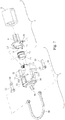
- brewing 1 unit is illustrated in an exploded view in which water injection assembly 2 comprises a heater 5 which is placed in direct fluid connection with a guide support 6 and a capsule cage 7.
- the heater may be a thermoblock as known per se.
- the capsule cage 7 has typically the form of a cup to enclose the capsule in closure with the capsule holding assembly 3.
- the capsule cage 7 is inserted in a cylindrical housing 8 of the guide support as also apparent in Figure 6 .
- Sealing means 70 may be provided to ensure a watertight connection between the cage 7 and the guide support 6.
- a water line 25 is provided through the water injection assembly to transport water in the capsule cage.
- the capsule cage also possesses opening members such as blades 10 to pierce the capsule for enabling water to be introduced into the capsule.
- the cage 7 is therefore also slightly moveable by the effect of the water pressure relatively to the cylindrical housing 8.
- the cage acts as a piston to increase the tightness at the edge of the capsule and the puncturing plate 13.
- the capsule may comprise a small sealing member at its edge, e.g., an annular rubber joint, for improving the tightness and facilitating the removal of the capsule from the capsule cage.
- brewing unit 1 comprises capsule opening means, such as blades 10, located in the brewing chamber 7' and arranged to open capsule 9 by penetration thereof in straight direction 3', in particular by closing the holding assembly 3 along straight direction 3' and thereby urging the capsule against the capsule opening means in the closure movement of assembly 3.
- capsule opening means such as blades 10
- a system comprising a piston-type brewing chamber and a capsule with its own sealing member is described in WO 2008/037642 .
- the capsule holding assembly 3 comprises a general tubular cover 11 that fits onto an internal capsule holding element 12.
- the element 12 comprises an internal housing for receiving the puncturing plate 13 therein.
- the cover 11 and capsule holding element 12 are associated in a fixed relationship by any suitable connection such as welding or tight mechanical fitting.
- the puncturing plate 13 is also fixed inside the element 12.
- An opening structure is formed at the surface of the plate such as a memori of puncturing reliefs. This structure serves to tear a foil member of the capsule (not shown) to enable the beverage delivery of the capsule after a certain delay corresponding to a rise in pressure in the capsule.
- the delay for opening the capsule can be controlled by different parameters such as the thickness and material of the foil member of the capsule, the shape and number of reliefs, the static pressure of the pump, etc.
- the brewing unit could be based on a different brewing principle.
- the opening plate could be omitted, or placed in the capsule itself, or replaced by a simple filter plate.
- a single-serve capsule 9 can be manually inserted in the passage 16 of the brewing unit.
- the capsule has a cup-shaped body 91 and a puncturable membrane 90 that seals the body in a gastight manner.
- the capsule extends radially by an annular rim 92 which is guided during its insertion by lateral slits 26 provided in the passage 4.
- the membrane 90 of the capsule is so placed in contact with the puncture plate 13 at the closure of the brewing unit, i.e., when the front assembly 3 is rotated in direction A and the capsule cage is pushed in closure on the plate.
- the upper side 93 of the body of the capsule is pierced by the piercing elements 10 to allow water to be injected in the capsule.
- the rim 92 of the capsule is also pinched by both the edge of the capsule cage 7 and the puncture plate 13 in a watertight manner.
- the watertight closure must resist high water pressure, i.e., at least 10 bar, in the capsule cage.
- water is injected by a high pressure pump (not shown) in the capsule.
- a pressure in the capsule is established that leads to the puncturing of the membrane against the puncture plate.
- the puncture operation can be delayed more or less depending, in particular, on the capsule and puncture plate designs.
- the capsule itself can be made of aluminium and/or plastic. It can contain ground coffee or other food ingredients.
- the assembly of the cover 11 and capsule holding element 12 enables to delimit a front internal volume serving as a receiver 140 for the brewed liquid.
- This receiver may constitute an intermediate chamber for preserving the foam and slowing down the liquid before it exits through the delivery duct 14.
- the connection of the capsule holding assembly 3 and the water injection assembly 2 is carried out by a helical connection means. More particularly, the capsule holding element 12 has a pair of spiral or helicoidal guiding slots 16 into which are engaged a pair of radial pins 17 of the guide support 6. Therefore, in the mode of Figure 3 , the capsule holding assembly 3 and the water injection assembly 2 are spaced apart relatively one another with the capsule passage being positioned at the top for enabling the capsule to be inserted simply by gravity fall. After insertion, the capsule is maintained in the capsule holding assembly in position in front of the plate 13 before closure.
- the brewing unit of the invention may be associated with retaining means, such as bumps optionally formed in capsule guiding slots of the brewing unit, for retaining the ingredient capsule between the assemblies when the assemblies are in their open position.
- the retaining means are optionally part of or movable with the assembly that is movable outwards from and inwards into the outermost casing, as for example shown in the embodiments of in the Figures.
- Figs 2a, 2b and 7 to 11 in which the same numeric references generally designate the same elements, show a beverage machine with a main casing 80 and a brewing unit 1 having a translational closure mechanism along a straight line 3' in a telescopic manner.
- Brewing unit 1 comprises a capsule holding assembly with a beverage outlet 14 forming a first movable assembly 3 and a water injection assembly with a water inlet or line 25 in casing 80 forming a second fixed assembly 2.
- Each assembly 2,3 delimits at least part of a brewing chamber 7' for containing an ingredient capsule 9.
- the capsule injection assembly may be movable and the capsule holding assembly may be fixed or movable.
- Holding assembly 3 has a tubular cover 11 and is movable away from the cooperating injection assembly 2 into an open position, as shown in Fig. 2a , within the beverage machine for forming between assemblies 2,3 a passage 22 for inserting into and/or removing from the brewing unit 1 an ingredient capsule 9. Furthermore, holding assembly 3 is movable to the injection assembly 2 into a closed position, as shown in Fig. 2b , for forming brewing chamber 7' that is sealed around capsule 9 in the brewing position. Moreover, holding assembly 3 has an outer face 11' that is brought into a position substantially adjacent and coplanar with an outer face 82 of outermost casing 80.
- holding assembly 3 is movable with its tubular cover 11 in translation along a straight direction 3' from the closed position to the open position and vice versa.
- beverage machine has a handle 30 for driving the holding assembly in and out from casing 80.
- the movable assembly can be arranged as a spring loaded push assembly that can be moved by hand, similarly to a telescopic retractable ball-point pen, and that can be telescopically moved back and forth between the open and the closed position in which the brewing chamber is water-tightly sealed around the capsule for its extraction.
- a passage 22 is provided for the insertion of capsule 9 into brewing unit 1.
- passage 22 formed between spaced apart holding assembly 3 and injection assembly 2 through tubular cover 11 permits insertion of capsule 9 into brewing unit 1 via an opening 22' of passage 22.
- opening 22' is displaced in translation in a direction 3' transverse to the direction 9' of introduction of capsules 9 into passage 22. Opening 22', indicated in doted lines in Fig.
- casing 80 and tubular cover 11 have generally flat, slightly arched, corresponding matching surfaces so that passage opening 22', in its translational movement, slides under closure part 81 parallelly thereto.
- FIGs 7 to 11 illustrate in greater details brewing unit 1 of the exemplary beverage machine of the invention shown in Figs 2a and 2b .
- Brewing unit 1 shown without its tubular cover 11, comprises, in a way similar to the previous embodiment, a water injection assembly 2 and a capsule holding assembly 3.
- the water injection assembly 2 comprises a heater 5, e.g., a thermoblock, which is placed in direct fluid connection with a guide support 6 and a capsule cage 7.
- the capsule cage 7 has typically the form of a cup to enclose the capsule in closure with the capsule holding assembly 3.
- the capsule cage 7 is inserted in a cylindrical housing 8 of the guide support. Sealing means 70 may be provided to ensure a watertight connection between the cage 7 and the guide support 6.
- a water line 25 is provided through the water injection assembly to guide water in the capsule cage.
- the capsule cage also possesses opening members such as blades 10 to pierce the capsule for enabling water to be introduced into the capsule.
- the brewing unit further comprises a capsule handling assembly 3 which comprises a main body portion 15 including an upper passage 22 for inserting the capsule in a capsule cage 7.
- a puncturing plate 13 is lodged inside and in the bottom of the housing.
- On the front side of the body portion 15 is provided a beverage delivery duct 19 for delivering the beverage from the capsule cage 7 through the puncturing plate 13 to a receptacle (e.g., a cup) via outlet duct 14 of tubular cover 11.
- a receptacle e.g., a cup
- the water injection assembly 2 is mounted in the capsule handling assembly 3 in a linearly moveable fashion via two lateral pins 20, 21 placed on each side of the guide support 6 which respectively engage a pair of guiding slots 221, 222 provided on the side of the handling assembly 3.
- the pins 20, 21 are directly linked to a lever assembly 30, 31, 32.
- the lever assembly is axially connected along a transversal axis 34 to the pins 20, 21.
- the lever assembly has a U-shaped lever 30 and two guiding rods 31, 32 connected along axis 34. The rods prolong the lever beyond the axis 34 in a linear direction with small interior pins 35, 36 which slide along downward extensions 23, 24 of the slots.
- Figures 8 and 9 show the brewing unit in open configuration with the lever 30 placed upwards. In this position, the two assemblies are distant for leaving a large gap 40 enabling insertion and placement of the capsule. The capsule is retained by lateral bumps 41 formed in vertical slots 42 adapted for guiding the rim of the capsule in its vertical fall. Closure of the brewing unit is obtained by handling and pulling the lever down in the position of Figure 10 . This result in the guiding support 6 being pulled via the pins 20, 21 and in placing the capsule cage 7 in tight contact pressure of its annular free edge 73 against the puncturing plate 13.
- the water injection assembly is preferably fixed whereas the front capsule handling assembly is mobile and moved backwards to the water injection assembly.
- the body portion 15 may comprise external guiding pins 71, 72 which may engage an outer casing (not shown) of the machine to which the brewing unit can fit in.
- the water injection assembly could be mobile and the front part be fixed.
- the beverage machine has an outermost casing 80 and one of its brewing unit assemblies 2,3 can be moved or telescoped out or through casing 80 for inserting/removing an ingredient capsule 9 and can be retracted into outermost casing 80 for bringing brewing unit 1 into its capsule extraction or brewing configuration.
- the brewing machine of the invention is of a particularly simple conception with fewer components.
- the fluidic system is fixed in the machine whereas the beverage collecting system is mobile for closure.
- An advantage is that the fluidic system can be made more compact so that the heat loss is reduced and the manufacturing of the machine is simplified.
- the heater can remain static compared to existing brewing units in which the heater moves with the injection head.
- Such unoccupied volumes occur in retracted prior art machines which require a change of direction of the moving assembly within the machine's outermost casing, e.g. a horizontal capsule drawer that is combined with a vertical elevator-type system for bringing the drawer with the capsule into the brewing position within the machine as for example disclosed in the abovementioned US 3,260,190 and WO 2005/072574 .
Description
- The present invention relates to a beverage brewing unit using capsules that contain a food ingredient for preparing a beverage or like food. The brewing unit is of simpler conception and of lower cost compared to existing brewing units.
- One problem encountered is the positioning of the capsule in the device and the closing of the latter around the capsule to perform the brewing process. The capsule usually has to be positioned by the user on a capsule support or in a housing, then the device is closed manually or automatically around the capsule.
- It is important to correctly position the capsule so that the device closes correctly around the latter and a good seal is thus achieved to ensure good conditions of extraction. Bad positioning may damage the capsule, and thus affect the conditions of extraction. The loading of the capsule must also be easy, without trial and error as to the correct position of the capsule in the device. The loading must also be as rapid as possible and not require excessive manipulations. Hence, devices exist that propose the insertion of the capsule in a vertical plane and the movement of the extraction or infusion parts along a horizontal plane around the capsule. Such systems have the advantages of allowing a loading from the top piggy-bank fashion, and makes for rapid loading. The positioning of the capsule is then taken over by the movement of a movable part that pushes the capsule against another part such as a water heater. However, these devices are complex to produce and are not suitable for low-cost and therefore entry-level coffee machines for the consumer market. They are therefore usually intended for the business market such as restaurants, bars or communities. For example, patent application
WO 98/47418 -
WO 2005/004683 relates to a capsule brewing device comprising: a first part; a second part that can be moved relative to the first part; a housing for the capsule and defining, in a closed position of the movable part against the fixed part, an extraction position of the capsule along an axis in said housing; an insertion and positioning part comprising means for guiding the capsule arranged so as to insert the capsule by gravity and position said capsule in an intermediate position; a drink pouring system; and the second movable part is so arranged and constructed to move the capsule from the intermediate position into the extraction position when the device is closed. -
EP 1 721 553 discloses a brewing unit for coffee machines using capsules. The unit has a front part with a beverage outlet and a rear part with a hot water inlet. The front part and the rear part are mounted in-between a pair of facing shoulder guide members. The front part is movable in-between these guide members to be urged against the rear part so as to form with the rear part a brewing chamber for accommodating a capsule to be extracted, whereby an unoccupied volume is left in front of the front member between the guide members within the machine. -
EP 1 659 547 relates to a beverage machine for making infusions, in particular, espresso coffee. The machine includes an infusion chamber within a brewing unit that has a movable front part with a return spring and a beverage outlet duct that extends through the assembly's outer housing. The movable front part cooperates with a rear part that is movable within the housing and that can be pushed against the movable front part to compress the return spring whereby the outlet duct slides through the assembly's outer housing. The pod is passed through the external housing to the infusion chamber via a rigid pod feed channel and then the pod is transferred into the infusion chamber by an external bushing on the movable rear part of the brewing unit which is provided with a cam-like path for moving the rear part. This arrangement involves several problems. The pod must be moved during the closure of the brewing chamber and this can cause blocking and it also makes the retaining means of the pod more complex. Moreover, opening and closing the brewing chamber involves simultaneously a linear displacement of the movable rear part within the housing, of the movable front part within the housing and of the outlet duct through the housing which increases the risk of hyper-guiding and jamming or improper alignment of the various parts that linearly move one relative to another. The fluid system comprises a moving assembly which makes the fluid system more complex to assemble. When upon extraction brewing unit is re-opened for removing the pod, pressurized water contained within the infusion chamber may project outside the hosing. Furthermore, an unoccupied volume is left within the machine between the front member and the casing when the outlet duct is in its retracted position. -
US 3,260,190 andWO 2005/072574 disclose a coffee machine having a removable drawer for positioning a coffee can therein. The drawer can be slid horizontally into the coffee machine and lifted towards a water injection arrangement.WO 2006/023309 discloses a coffee machine with a slidable drawer for the introduction of a coffee cartridge into the machine. The drawer is movable between an open and a closed position and has two cartridge half-shells that are pivotable against each other to form a brewing chamber when the drawer is in the closed position and pivotable apart when the drawer is slid out from the machine.US 6,966,251 discloses a coffee machine having a horizontally slidable drawer for positioning a capsule therein. When slid into the machine, the drawer can be moved upwards towards a fixed capsule cage for form a brewing chamber for a capsule.EP 1 566 126 discloses a coffee machine with a vertical brewing unit for accommodating coffee pods. The brewing unit has a fixed upper part and a movable lower part for holding a pod and that can be pulled up for closing the brewing unit and let down for inserting or removing a pod. - Further brewing units are disclosed in
EP 0 730 425 ,EP 0 862 882 ,EP 1 219 217 ,EP 1 480 540 ,EP 1 635 680 ,EP 1 669 011 ,EP 1 774 878 ,EP 1 776 026 ,EP 1 893 064 ,FR 2 424 010 US 3,260,190 ,US 4,760,774 ,US 5,531,152 ,US 7,131,369 ,US 2005/0106288 ,US 2006/0102008 ,WO 2005/002405 ,WO 2005/016093 ,WO 2006/005756 ,WO 2006/066626 andWO 2007/135136 . - One aspect which is not part of the present invention relates to a beverage machine having an outermost casing and a brewing unit that comprises a first assembly and a second assembly cooperating together. Each assembly delimits part of a brewing chamber for containing an ingredient capsule. At least one of these assemblies is: movable away from the cooperating assembly into an open position within this beverage machine for forming between these assemblies a passage for inserting into and/or removing from the brewing unit an ingredient capsule; and movable to the cooperating assembly into a closed position for forming the brewing chamber. One of these assemblies is movable along a straight direction from the closed position to the open position and vice versa. In particular, this assembly is movable along a straight direction in translation or helicoidally. Furthermore, this assembly is movable outwards from the outermost casing and movable inwards into the outermost casing between the open and closed positions, in particular movable in a telescopic manner, e.g. by sliding or passing this assembly within an opening of the outermost casing, outwards and inwards the casing like the cylindrical sections of a telescope. The invention is defined in claim 1 and relates to a beverage machine that comprises: a brewing unit which can be opened and closed for introducing or removing an ingredient capsule, when opened, and for brewing this ingredient when closed; a passage that has an opening and that is arranged for guiding this ingredient capsule from the passage opening into the brewing unit; and a closure member for closing the passage opening when the brewing unit is closed. The closure member is relatively movable, in particular in a relative sliding movement, over the passage opening and generally parallel thereto from: an open relative position in which said ingredient capsule can be passed into the brewing unit via the passage; to a closed relative position, in which the passage opening is closed by the closure member.
- The present invention does not relate to a brewing unit for an easy insertion of a capsule but of simpler conception, in particular, that requires fewer moving parts, a more direct fluid connection with less need for tubings, a more compact design, a more user-friendly closure actuation and/or which prevents hot water projections when opened upon brewing. The invention does not relate to a beverage brewing unit comprising: a capsule holding part for holding a capsule in a position during insertion by gravity of the capsule in the brewing unit; and a water injection assembly for at least partially enclosing the capsule and providing water in the capsule. The capsule holding part forms a front part of the unit and is mounted to the capsule injection assembly in a manner to be displaceable along a substantially horizontal path whereas the water injection assembly is a rear fixed part of the unit.
- Other features of the beverage machine and brewing unit of the invention are set forth in the dependent claims.
- The combination of a beverage machine and a single-serve capsule is not part of the claimed invention, wherein the capsule comprises a cup and a closing membrane which is sealed on the cup for forming a gastight enclosure containing ground coffee. The membrane of the capsule forms the beverage delivery side of the capsule that is torn in contact with the puncture plate of the machine. Tearing of the membrane of the capsule is typically obtained by the rise in pressure that takes place in the capsule during injection of water in the capsule. The membrane of the capsule is so perforated to provide many small apertures from which the beverage can be released.
- Further features and advantages of the invention will appear in the description of the detailed description.
-
-
Figures 1a and 1b show a beverage machine according to the invention with a brewing unit assembly that is helicoidally extendible out of and retractable into the machine's outermost casing. -
Figures 2a and 2b show another beverage machine according to the invention with a brewing unit assembly that is translatably telescopable out of and retractable into the machine's outermost casing. -
Figure 3 is an exploded view of a brewing unit of the beverage machine ofFigures 1a and 1b . -
Figure 4 is a perspective view of the brewing unit ofFigure 3 in the capsule insertion mode and of a capsule. -
Figure 5 is a perspective view of a brewing unit ofFigure 3 in a closure mode of the unit about the capsule and in ready mode for brewing. -
Figure 6 is cross sectional view of the brewing unit ofFigures 3 to 5 . -
Figure 7 is an exploded view of a brewing unit of the beverage machine ofFigures 2a and 2b . -
Figure 8 is a perspective view of the brewing unit ofFigure 7 in the capsule insertion mode. -
Figure 9 is a cross sectional view of the brewing unit ofFigure 8 . -
Figure 10 is a perspective view of a brewing unit ofFigure 7 in a closure mode of the unit about the capsule and in ready mode for brewing. -
Figure 11 is a cross sectional view of the brewing unit ofFigure 10 . - A first embodiment of the invention is now described in relation to
Figures 1a, 1b and 3 to 6 . -
Figs 1a and 1b show a beverage machine with amain casing 80 and a brewing unit 1 having a helicoidal closure mechanism along a straight line, details of brewing unit 1 being illustrated inFigs 3 to 6 . - Brewing unit 1 comprises a capsule holding assembly with a
beverage outlet 14 forming a firstmovable assembly 3 and a water injection assembly with a water inlet orline 25 incasing 80 forming a second fixed assembly 2. Eachassembly 2,3 delimits at least part of a brewing chamber 7' for containing aningredient capsule 9. - In a variation, the capsule injection assembly may be movable and the capsule holding assembly may be fixed or movable.
- Holding
assembly 3 has atubular cover 11 and is movable away from the cooperating injection assembly 2 into an open position within the beverage machine for forming between assemblies 2,3 apassage 4 for inserting into and/or removing from the brewing unit 1 aningredient capsule 9. Furthermore, holdingassembly 3 is movable to the injection assembly 2 into a closed position for forming brewing chamber 7'. - In accordance with the invention, holding
assembly 3 is movable with itstubular cover 11 helicoidally along a straight direction 3' from the closed position to the open position and vice versa. Holdingassembly 3 has an outer part that is arranged to be hand-held for being driven directly by hand to and from injection assembly 2, inwards and outwards theoutermost casing 80. For this purpose,outlet 14 protrudes out fromtubular cover 11 so as to form a gripping means for safe holding by a human hand, in order to facilitate turning and driving by hand of holdingassembly 3. - Brewing unit 1 is located in a top part of
casing 80 above alower part 85 thereof, typically delimiting a cavity which can be used for a water reservoir and/or a used capsule collector. As shown inFigs 1a and 1b , the holdingassembly 3 is located and movable adjacent the upper front edge ofcasing 80. Holdingassembly 3 is movable outwards from a front part of casing 80 to an outermost position (Fig. 1a ) for insertingcapsule 9 and inwards to an innermost position (Fig. 1b ) for brewing insertedcapsule 9 within capsule chamber 7'. Holdingassembly 3 has an outer face 11' that is brought into a position substantially adjacent and coplanar with anouter face 82 ofoutermost casing 80, which simplifies wiping or cleaning of the outer surface of the beverage machine abouttelescopable assembly 3. - Similarly, it is also contemplated, as variations, to provide an assembly of the brewing unit that is retractable upright in a top part of the beverage machine, laterally on a side of the beverage machine or in a rear part of the machine.
- A
passage 4 is provided for the insertion ofcapsule 9 into brewing unit 1. When brewing unit 1 is open, i.e. when holdingassembly 3 is in its outermost position,passage 4 is formed between spaced apart holdingassembly 3 and injection assembly 2 throughtubular cover 11 and permits the insertion ofcapsule 9 into brewing unit 1 via an opening 4' ofpassage 4. When brewing unit 1 is closed, i.e. when holdingassembly 3 is moved to its innermost or retracted position, opening 4' is helicoidally displaced in a direction transverse to the direction 9' of introduction ofcapsules 9 intopassage 4. Opening 4' indicated in doted lines inFig. 1b , is then entirely hidden under a plate-like edge part that forms aclosure part 81 ofcasing 80 for closing passage opening 4'.Casing 80 andtubular cover 11 have generally flat, slightly arched, corresponding matching surfaces so that passage opening 4', in its helicoidal movement, slides underedge part 81 parallelly thereto. - In a variation it is of course possible to provide a movable closure part that is displaced relative to a movable or fixed passage opening.
- By providing such a sliding closure mechanism of the
capsule insertion passage 9, instead of a hinged prior art cover-like closure, safety of the beverage machine is increased. Indeed, even when brewing unit 1 is opened so as to allow the escape from chamber 7' of pressurised fluid intopassage 4 substantially along the direction 9' of introduction ofcapsules 9, possible hot liquid projections at reopening of brewing unit 1 are safely contained withinpassage 9 undercover 81 until depressurisation so that the user will not be exposed to such projections. In the closed configuration of passage opening 4', the closure part may slightly extend, e.g. up to a few millimetres, such as 0.5 to 5 mm or 1 to 3 mm, over the edge of opening 4' to increase the protection against liquid and/or vapour projections at re-opening of brewing chamber 7' and slightly delay actual uncovering ofpassage 4 at opening. - This is for example illustrated in the embodiment shown in
Fig. 2b and discussed below, in which the edge of passage opening 22' is retracted undercover part 81 by a short distance beyond the edge ofcasing 80. - The brewing unit 1 of the embodiment shown in
Figs 1a, 1b and 3 to 6 is of a rotary type. As illustrated in greater details inFigs 3 to 6 , it comprises a water injection assembly 2 and acapsule holding assembly 3. Thecapsule holding assembly 3 is mounted onto the water injection assembly 2 according to a relationship of helical or spiral movement. - In the mode of
Figure 4 , thecapsule holding assembly 3 is positioned with acapsule passage 4 being oriented upwardly to receive a capsule therethrough via its opening 4' along direction 9' under the effect of gravity. The holding part 2 represents the front part of the brewing unit 1 and has abeverage delivery duct 14 for guiding the beverage to the receptacle. As discussed above, this front part may be helically drawn out and moved back into the machine'scasing 80. - In
Figure 3 , brewing 1 unit is illustrated in an exploded view in which water injection assembly 2 comprises a heater 5 which is placed in direct fluid connection with aguide support 6 and acapsule cage 7. The heater may be a thermoblock as known per se. Thecapsule cage 7 has typically the form of a cup to enclose the capsule in closure with thecapsule holding assembly 3. Thecapsule cage 7 is inserted in a cylindrical housing 8 of the guide support as also apparent inFigure 6 . Sealing means 70 may be provided to ensure a watertight connection between thecage 7 and theguide support 6. Awater line 25 is provided through the water injection assembly to transport water in the capsule cage. The capsule cage also possesses opening members such asblades 10 to pierce the capsule for enabling water to be introduced into the capsule. Thecage 7 is therefore also slightly moveable by the effect of the water pressure relatively to the cylindrical housing 8. The cage acts as a piston to increase the tightness at the edge of the capsule and the puncturingplate 13. The capsule may comprise a small sealing member at its edge, e.g., an annular rubber joint, for improving the tightness and facilitating the removal of the capsule from the capsule cage. - Hence, brewing unit 1 comprises capsule opening means, such as
blades 10, located in the brewing chamber 7' and arranged to opencapsule 9 by penetration thereof in straight direction 3', in particular by closing the holdingassembly 3 along straight direction 3' and thereby urging the capsule against the capsule opening means in the closure movement ofassembly 3. - A system comprising a piston-type brewing chamber and a capsule with its own sealing member is described in
WO 2008/037642 . - The
capsule holding assembly 3 comprises a generaltubular cover 11 that fits onto an internalcapsule holding element 12. Theelement 12 comprises an internal housing for receiving the puncturingplate 13 therein. Thecover 11 andcapsule holding element 12 are associated in a fixed relationship by any suitable connection such as welding or tight mechanical fitting. The puncturingplate 13 is also fixed inside theelement 12. An opening structure is formed at the surface of the plate such as a serie of puncturing reliefs. This structure serves to tear a foil member of the capsule (not shown) to enable the beverage delivery of the capsule after a certain delay corresponding to a rise in pressure in the capsule. The delay for opening the capsule can be controlled by different parameters such as the thickness and material of the foil member of the capsule, the shape and number of reliefs, the static pressure of the pump, etc. Of course, the brewing unit could be based on a different brewing principle. For instance, the opening plate could be omitted, or placed in the capsule itself, or replaced by a simple filter plate. - In
Figure 4 , a single-serve capsule 9 can be manually inserted in thepassage 16 of the brewing unit. The capsule has a cup-shapedbody 91 and apuncturable membrane 90 that seals the body in a gastight manner. The capsule extends radially by anannular rim 92 which is guided during its insertion bylateral slits 26 provided in thepassage 4. Themembrane 90 of the capsule is so placed in contact with thepuncture plate 13 at the closure of the brewing unit, i.e., when thefront assembly 3 is rotated in direction A and the capsule cage is pushed in closure on the plate. During closure, the upper side 93 of the body of the capsule is pierced by the piercingelements 10 to allow water to be injected in the capsule. Therim 92 of the capsule is also pinched by both the edge of thecapsule cage 7 and thepuncture plate 13 in a watertight manner. The watertight closure must resist high water pressure, i.e., at least 10 bar, in the capsule cage. During brewing, water is injected by a high pressure pump (not shown) in the capsule. A pressure in the capsule is established that leads to the puncturing of the membrane against the puncture plate. The puncture operation can be delayed more or less depending, in particular, on the capsule and puncture plate designs. Once the capsule is pierced, beverage can be released from the capsule through the perforation, through the puncture plate (which has small channels/holes). The beverage is collected and drained via the collectingduct 19 leading intooutlet duct 14 oftubular cover 11. - The capsule itself can be made of aluminium and/or plastic. It can contain ground coffee or other food ingredients.
- As apparent in
Figure 6 , the assembly of thecover 11 andcapsule holding element 12 enables to delimit a front internal volume serving as a receiver 140 for the brewed liquid. This receiver may constitute an intermediate chamber for preserving the foam and slowing down the liquid before it exits through thedelivery duct 14. - The connection of the
capsule holding assembly 3 and the water injection assembly 2 is carried out by a helical connection means. More particularly, thecapsule holding element 12 has a pair of spiral orhelicoidal guiding slots 16 into which are engaged a pair ofradial pins 17 of theguide support 6. Therefore, in the mode ofFigure 3 , thecapsule holding assembly 3 and the water injection assembly 2 are spaced apart relatively one another with the capsule passage being positioned at the top for enabling the capsule to be inserted simply by gravity fall. After insertion, the capsule is maintained in the capsule holding assembly in position in front of theplate 13 before closure. - Hence, the brewing unit of the invention may be associated with retaining means, such as bumps optionally formed in capsule guiding slots of the brewing unit, for retaining the ingredient capsule between the assemblies when the assemblies are in their open position. The retaining means are optionally part of or movable with the assembly that is movable outwards from and inwards into the outermost casing, as for example shown in the embodiments of in the Figures.
- Detailed embodiments of the manner by which the capsule can be retained in the brewing unit in position before closure are for example described in
WO2005/004683 . In order to close the unit about the capsule and retractassembly 3 intocasing 80, thefront assembly 3 is rotated manually in clockwise direction A as illustrated inFigure 4 to the closure position ofFigure 5 . The closure position is obtained, for instance, by a quarter of turn or by a longer angular movement eventually depending on the geometry of the guiding means 16, 17. As thefront assembly 3 is turned, it also moves rearward, in direction B, in a helical path by thepins 17 that are guided along theslots 16. Therefore, thebeverage delivery duct 14 moves from a side position ofFigure 1 to a downward position ofFigure 3 . The final closure position is shown infigure 4 in which thecapsule cage 7 exerts a tight closure pressure on theedge 18 of the puncturingplate 13 while preferentially also pinching a rim or seal of the capsule. - It should be noticed that the manual action of the front capsule holding assembly could be replaced by motorized action if a motor is integrated to the design of the brewing unit.
-
Figs 2a, 2b and 7 to 11 , in which the same numeric references generally designate the same elements, show a beverage machine with amain casing 80 and a brewing unit 1 having a translational closure mechanism along a straight line 3' in a telescopic manner. - Brewing unit 1 comprises a capsule holding assembly with a
beverage outlet 14 forming a firstmovable assembly 3 and a water injection assembly with a water inlet orline 25 incasing 80 forming a second fixed assembly 2. Eachassembly 2,3 delimits at least part of a brewing chamber 7' for containing aningredient capsule 9. In a variation, the capsule injection assembly may be movable and the capsule holding assembly may be fixed or movable. - Holding
assembly 3 has atubular cover 11 and is movable away from the cooperating injection assembly 2 into an open position, as shown inFig. 2a , within the beverage machine for forming between assemblies 2,3 apassage 22 for inserting into and/or removing from the brewing unit 1 aningredient capsule 9. Furthermore, holdingassembly 3 is movable to the injection assembly 2 into a closed position, as shown inFig. 2b , for forming brewing chamber 7' that is sealed aroundcapsule 9 in the brewing position. Moreover, holdingassembly 3 has an outer face 11' that is brought into a position substantially adjacent and coplanar with anouter face 82 ofoutermost casing 80. - In accordance with the invention, holding
assembly 3 is movable with itstubular cover 11 in translation along a straight direction 3' from the closed position to the open position and vice versa. - As discussed below, beverage machine has a
handle 30 for driving the holding assembly in and out from casing 80. However, like in the previous helicoidal closure embodiment it is possible to provide an assembly that can be hand-held for being driven directly by hand to and from the injection assembly, inwards and outwards the outermost casing. For example, the movable assembly can be arranged as a spring loaded push assembly that can be moved by hand, similarly to a telescopic retractable ball-point pen, and that can be telescopically moved back and forth between the open and the closed position in which the brewing chamber is water-tightly sealed around the capsule for its extraction. - A
passage 22 is provided for the insertion ofcapsule 9 into brewing unit 1. As shown inFig. 2a , when brewing unit 1 is open, i.e. when holdingassembly 3 is in its outermost position,passage 22 formed between spaced apart holdingassembly 3 and injection assembly 2 throughtubular cover 11 permits insertion ofcapsule 9 into brewing unit 1 via an opening 22' ofpassage 22. When brewing unit 1 is closed, i.e. when holdingassembly 3 is moved to its innermost or retracted position, opening 22' is displaced in translation in a direction 3' transverse to the direction 9' of introduction ofcapsules 9 intopassage 22. Opening 22', indicated in doted lines inFig. 2b , is then entirely hidden under a plate-like edge part that forms aclosure part 81 ofcasing 80 for closing passage opening 22'.Casing 80 andtubular cover 11 have generally flat, slightly arched, corresponding matching surfaces so that passage opening 22', in its translational movement, slides underclosure part 81 parallelly thereto. -
Figures 7 to 11 illustrate in greater details brewing unit 1 of the exemplary beverage machine of the invention shown inFigs 2a and 2b . Brewing unit 1, shown without itstubular cover 11, comprises, in a way similar to the previous embodiment, a water injection assembly 2 and acapsule holding assembly 3. The water injection assembly 2 comprises a heater 5, e.g., a thermoblock, which is placed in direct fluid connection with aguide support 6 and acapsule cage 7. Thecapsule cage 7 has typically the form of a cup to enclose the capsule in closure with thecapsule holding assembly 3. Thecapsule cage 7 is inserted in a cylindrical housing 8 of the guide support. Sealing means 70 may be provided to ensure a watertight connection between thecage 7 and theguide support 6. Awater line 25 is provided through the water injection assembly to guide water in the capsule cage. The capsule cage also possesses opening members such asblades 10 to pierce the capsule for enabling water to be introduced into the capsule. - The brewing unit further comprises a
capsule handling assembly 3 which comprises amain body portion 15 including anupper passage 22 for inserting the capsule in acapsule cage 7. A puncturingplate 13 is lodged inside and in the bottom of the housing. On the front side of thebody portion 15 is provided abeverage delivery duct 19 for delivering the beverage from thecapsule cage 7 through the puncturingplate 13 to a receptacle (e.g., a cup) viaoutlet duct 14 oftubular cover 11. - The water injection assembly 2 is mounted in the
capsule handling assembly 3 in a linearly moveable fashion via twolateral pins guide support 6 which respectively engage a pair of guidingslots 221, 222 provided on the side of the handlingassembly 3. Thepins lever assembly transversal axis 34 to thepins U-shaped lever 30 and two guidingrods axis 34. The rods prolong the lever beyond theaxis 34 in a linear direction with smallinterior pins downward extensions -
Figures 8 and 9 show the brewing unit in open configuration with thelever 30 placed upwards. In this position, the two assemblies are distant for leaving alarge gap 40 enabling insertion and placement of the capsule. The capsule is retained bylateral bumps 41 formed invertical slots 42 adapted for guiding the rim of the capsule in its vertical fall. Closure of the brewing unit is obtained by handling and pulling the lever down in the position ofFigure 10 . This result in the guidingsupport 6 being pulled via thepins capsule cage 7 in tight contact pressure of its annularfree edge 73 against the puncturingplate 13. In this embodiment also, the water injection assembly is preferably fixed whereas the front capsule handling assembly is mobile and moved backwards to the water injection assembly. It can be noticed that thebody portion 15 may comprise external guiding pins 71, 72 which may engage an outer casing (not shown) of the machine to which the brewing unit can fit in. - In an alternative, the water injection assembly could be mobile and the front part be fixed.
- Hence, the beverage machine has an
outermost casing 80 and one of itsbrewing unit assemblies 2,3 can be moved or telescoped out or throughcasing 80 for inserting/removing aningredient capsule 9 and can be retracted intooutermost casing 80 for bringing brewing unit 1 into its capsule extraction or brewing configuration. - The brewing machine of the invention is of a particularly simple conception with fewer components. In a particular embodiment, the fluidic system is fixed in the machine whereas the beverage collecting system is mobile for closure. An advantage is that the fluidic system can be made more compact so that the heat loss is reduced and the manufacturing of the machine is simplified. For example, the heater can remain static compared to existing brewing units in which the heater moves with the injection head.
- By retracting holding,
assembly 3, as a block, intocasing 80, the overall length is reduced so as to gain space in front of the beverage machine when the holdingassembly 3 is in its retracted position within the casing. This contrasts with prior art sliding brewing units, e.g. as disclosed in the abovementionedEP 1 659 547 andEP 1 721 553 , in which these blocks forming the brewing unit move entirely inside the machine's outermost casing, which thus requires an extra volume within the casing for allowing such internal movements. The volume gain and simplification of the brewing unit mechanism is also improved by providing a closure mechanism that operates in a straight line so as to avoid unoccupied volume within the machine in its retracted configuration. Such unoccupied volumes occur in retracted prior art machines which require a change of direction of the moving assembly within the machine's outermost casing, e.g. a horizontal capsule drawer that is combined with a vertical elevator-type system for bringing the drawer with the capsule into the brewing position within the machine as for example disclosed in the abovementionedUS 3,260,190 andWO 2005/072574 .
Claims (15)
- A beverage machine comprising:- a brewing unit (1) which can be opened for introducing or removing an ingredient capsule (9), and closed for brewing said ingredient;- a passage (4,22) that has an opening (4',22') and that is arranged for guiding said ingredient capsule (9) from the passage opening (4',22') into the brewing unit (1); and- a closing part (81) for closing the passage opening (4',22') when the brewing unit (1) is closed,wherein the closing part (81) is relatively movable over the passage opening (4',22') in a generally parallel relative movement thereto, in particular in a relative sliding movement, from:- an open relative position in which said ingredient capsule (9) can be passed into the brewing unit (1) via the passage (4',22'); to- a closed relative position, in which the passage opening (4',22') is closed by the closure member (81),the closing part (81) optionally extending over edges of the passage opening (4',22').
- The beverage machine of claim 1, wherein the closing part (81) is relatively movable in a direction (3') generally transverse to a direction (9') of the passage (4,22) along which direction (9') said ingredient capsules (9) are guided to the brewing unit (1).
- The beverage machine of claim 1 or 2, wherein the closing part (81) has a generally plate-like shape that is arranged flat over the passage opening (4',22') and relatively movable thereto, said machine having in particular a casing (80), such as an outermost casing, having a part (81) that forms the closing part.
- The beverage machine of any preceding claim, wherein the brewing unit comprises a first assembly (3) and a second assembly (2) cooperating together, at least one of said assemblies (2,3) being:- movable away from the cooperating assembly into an open position within said machine for forming between said assemblies at least part of said passage (4,22); and- movable to the cooperating assembly into a closed position for forming said brewing chamber (7'),the closing part (81) being optionally directly or indirectly fixed with said cooperating assembly.
- The beverage machine of claim 4, wherein the first assembly (3) is a capsule holding assembly (3) for holding a capsule in a position during insertion by gravity of the capsule (9) in the brewing unit, and wherein the second assembly (2) is a water injection assembly (2) for at least partially enclosing the capsule and providing water in the capsule.
- The beverage machine of claim 5, wherein the capsule holding assembly (3) forms a front part of the brewing unit and is mounted to the water injection assembly (2) in a manner to be displaceable along a substantially horizontal path whereas the water injection assembly (2) is a rear fixed part of the unit.
- The beverage machine of claim 6, wherein the capsule holding assembly (3) is mounted along connection means (16, 17, 20, 21, 23, 24, 221, 222) on the water injection assembly (2) that provides a rearward displacement of the capsule holding assembly (3), the connection means comprising in particular a combination of at least a pair of pins (17, 20, 21) that engage at least a pair of slots (16, 221, 222), said pair of pins (17, 20, 21) being optionally part of the water injection assembly (2) whereas the pair of slots (16, 221, 222) is part of the capsule holding assembly (3).
- The beverage machine of claim 7, wherein said pair of slots (221, 222) is arranged to provide a linear path of the capsule holding assembly (2) relative to the water injection assembly (3), such bverage brewing device optionally comprising a lever (30) for displacing the capsule holding assembly (3) towards the water injection assembly (2).
- The beverage machine of claim 8, wherein said pair of slots (16) is arranged to provide a spiral path of the capsule holding assembly (3) relative to the water injection assembly (2).
- The beverage brewing unit of any one of claims 5 to 9, wherein the capsule holding assembly (3) has an outer part that is arranged to be hand-held for being driven directly by hand to and from the injection assembly (2), the holding assembly (3) comprising in particular a protruding beverage duct (14, 19) serving as a gripping means.
- The beverage brewing unit according to any one of claims 5 to 10, wherein the capsule holding assembly (3) comprises means for opening a beverage delivery foil member (90) of the capsule (9), the opening means comprising in particular a plate (13, 18) with a series of puncturing reliefs for puncturing the foil member of the capsule (9) and collecting channels for the beverage.
- The beverage brewing unit according to any one of claims 5 to 11, wherein the capsule holding assembly (3) comprises a beverage duct (14, 19).
- The beverage brewing unit according to any one of claims 5 to 12, wherein the capsule holding assembly (3) comprises a capsule holding element (12) with a passage for the capsule (9).
- The beverage machine of any one of claims 4 to 13, which comprises an outermost casing (80) and wherein said at least one of said assemblies is movable along a straight direction (3') from said closed position to said open position and vice versa, such as movable along a straight direction (3') in translation or helicoidally, whereby said at least one of said assemblies is/are movable outwards from said outermost casing (80) and movable inwards into the outermost casing (80) between said open and closed positions, in particular in a telescopic manner.
- The beverage machine of claim 14,wherein the first assembly (3) is a capsule holding assembly (3) for holding a capsule (9) having a rim (92), and wherein the second assembly (2) is a water injection assembly (2) for at least partially enclosing the capsule and providing water in the capsule, and wherein the passage (4,22) is provided with lateral slits (26) or slots (42) for guiding the annular capsule rim (92) of said capsule (9) during insertion, the passage being provided with retaining means, such as bumps (41), between the assemblies in said open position for retaining said capsule between the assemblies in said open position.
Priority Applications (1)
| Application Number | Priority Date | Filing Date | Title |
|---|---|---|---|
| EP10161815.5A EP2218369B1 (en) | 2007-10-04 | 2008-08-08 | Beverage brewing unit |
Applications Claiming Priority (3)
| Application Number | Priority Date | Filing Date | Title |
|---|---|---|---|
| EP07117853 | 2007-10-04 | ||
| EP10161815.5A EP2218369B1 (en) | 2007-10-04 | 2008-08-08 | Beverage brewing unit |
| EP08802980A EP2205133B1 (en) | 2007-10-04 | 2008-08-08 | Beverage brewing unit |
Related Parent Applications (2)
| Application Number | Title | Priority Date | Filing Date |
|---|---|---|---|
| EP08802980A Division EP2205133B1 (en) | 2007-10-04 | 2008-08-08 | Beverage brewing unit |
| EP08802980.6 Division | 2008-08-08 |
Publications (3)
| Publication Number | Publication Date |
|---|---|
| EP2218369A2 EP2218369A2 (en) | 2010-08-18 |
| EP2218369A3 EP2218369A3 (en) | 2015-04-15 |
| EP2218369B1 true EP2218369B1 (en) | 2017-05-03 |
Family
ID=39059353
Family Applications (4)
| Application Number | Title | Priority Date | Filing Date |
|---|---|---|---|
| EP10161814.8A Active EP2218368B1 (en) | 2007-10-04 | 2008-08-08 | Beverage brewing unit |
| EP10161816.3A Ceased EP2218370A3 (en) | 2007-10-04 | 2008-08-08 | Beverage brewing unit |
| EP08802980A Revoked EP2205133B1 (en) | 2007-10-04 | 2008-08-08 | Beverage brewing unit |
| EP10161815.5A Active EP2218369B1 (en) | 2007-10-04 | 2008-08-08 | Beverage brewing unit |
Family Applications Before (3)
| Application Number | Title | Priority Date | Filing Date |
|---|---|---|---|
| EP10161814.8A Active EP2218368B1 (en) | 2007-10-04 | 2008-08-08 | Beverage brewing unit |
| EP10161816.3A Ceased EP2218370A3 (en) | 2007-10-04 | 2008-08-08 | Beverage brewing unit |
| EP08802980A Revoked EP2205133B1 (en) | 2007-10-04 | 2008-08-08 | Beverage brewing unit |
Country Status (23)
| Country | Link |
|---|---|
| US (2) | US8479640B2 (en) |
| EP (4) | EP2218368B1 (en) |
| JP (3) | JP5073062B2 (en) |
| KR (1) | KR20100075980A (en) |
| CN (3) | CN103169378B (en) |
| AR (1) | AR068675A1 (en) |
| AT (1) | ATE511375T1 (en) |
| AU (1) | AU2008306060C1 (en) |
| BR (1) | BRPI0818185B1 (en) |
| CA (1) | CA2701543C (en) |
| CL (1) | CL2008002964A1 (en) |
| DK (2) | DK201200078U4 (en) |
| ES (3) | ES2364797T3 (en) |
| HK (1) | HK1145619A1 (en) |
| IL (1) | IL204832A (en) |
| MX (1) | MX2010003570A (en) |
| PL (1) | PL2205133T3 (en) |
| PT (3) | PT2205133E (en) |
| RU (2) | RU2471398C2 (en) |
| SG (1) | SG184745A1 (en) |
| TW (1) | TW200934432A (en) |
| WO (1) | WO2009043630A2 (en) |
| ZA (1) | ZA201003081B (en) |
Families Citing this family (182)
| Publication number | Priority date | Publication date | Assignee | Title |
|---|---|---|---|---|
| EP1495702A1 (en) | 2003-07-10 | 2005-01-12 | Nestec S.A. | Device for the extraction of a cartridge |
| EP1867260B1 (en) | 2006-06-16 | 2010-05-26 | Nestec S.A. | Beverage distribution apparatus with support system and droplet recuperation for containers with different sizes |
| AU2008306060C1 (en) | 2007-10-04 | 2015-08-27 | Société des Produits Nestlé S.A. | Beverage brewing unit |
| CL2008002963A1 (en) | 2007-10-04 | 2010-01-22 | Nestec Sa | Heating device for a machine for the preparation of liquid food or drink, comprising a thermal unit with a metallic mass, through which the liquid circulates, and accumulates heat and supplies it to the liquid, and has one or more insured electrical components rigidly to the thermal unit; and machine. |
| JP2010540132A (en) | 2007-10-04 | 2010-12-24 | ネステク ソシエテ アノニム | Integrated heater for beverage preparation equipment |
| CN101977538B (en) * | 2008-03-20 | 2013-07-24 | 雀巢产品技术援助有限公司 | Beverage production device for producing a beverage from a single-use capsule |
| JP2011518015A (en) | 2008-04-22 | 2011-06-23 | ネステク ソシエテ アノニム | Module assembly for beverage production equipment |
| BRPI0917031A2 (en) * | 2008-08-08 | 2016-02-16 | Nestec Sa | beverage machine with carrier handle and configurable appearance and side functions |
| IT1392574B1 (en) * | 2008-12-30 | 2012-03-09 | Lavazza Luigi Spa | PODS MACHINE FOR COFFEE PREPARATION AND OTHER HOT DRINKS AND METHOD FOR THE PREPARATION OF PODS MACHINES |
| WO2010108700A1 (en) | 2009-03-23 | 2010-09-30 | Nestec S.A. | Pump mount in a beverage preparation machine |
| RU2526677C2 (en) * | 2009-05-06 | 2014-08-27 | Нестек С.А. | Beverage preparation machines with simplified maintenance |
| ES2449302T3 (en) | 2009-10-05 | 2014-03-19 | Nestec S.A. | Ergonomic cartridge removal device |
| JP5604522B2 (en) | 2009-10-05 | 2014-10-08 | ネステク ソシエテ アノニム | Cartridge type extraction device |
| US8557314B2 (en) | 2009-11-19 | 2013-10-15 | Nestec S.A. | Capsule and method for preparing a beverage such as coffee from said capsule |
| DK2506745T3 (en) | 2009-12-01 | 2013-12-16 | Nestec Sa | CARTRIDGE-extraction device |
| ES2456616T3 (en) | 2010-01-06 | 2014-04-23 | Nestec S.A. | Vibration resistant water tank of a beverage machine |
| IN2012DN06207A (en) | 2010-01-15 | 2015-09-25 | Nestec Sa | |
| PT2523586E (en) | 2010-01-15 | 2014-09-09 | Nestec Sa | Ergonomic ingredient holder and service unit coordination |
| EP2525693B2 (en) | 2010-01-21 | 2018-01-10 | Nestec S.A. | Beverage machine with removable liquid supply reservoir |
| AU2011222950B2 (en) | 2010-03-05 | 2014-10-09 | Nestec S.A. | Reduction of pump nuisance |
| RU2555958C2 (en) * | 2010-03-19 | 2015-07-10 | Нестек С.А. | Apparatus for beverages preparation with usage of capsules containing ingredients |
| EP2374383B2 (en) | 2010-04-07 | 2019-11-06 | Société des Produits Nestlé S.A. | Extraction system for the production of a beverage using a capsule |
| IT1400253B1 (en) * | 2010-05-17 | 2013-05-24 | Locati Trading S R L | DISPENSER GROUP FOR MACHINES FOR THE PRODUCTION OF INFUSES IN GENERAL, ESPRESSO IN PARTICULAR. |
| CA2799644C (en) * | 2010-05-19 | 2018-06-05 | Nestec S.A. | Beverage production system using capsules |
| CN102946775B (en) | 2010-05-21 | 2015-12-16 | 雀巢产品技术援助有限公司 | ergonomic dispenser interface |
| CN102905586B (en) | 2010-05-21 | 2015-11-25 | 雀巢产品技术援助有限公司 | Storable hot water or steam delivery device |
| WO2011144719A1 (en) | 2010-05-21 | 2011-11-24 | Nestec S.A. | Ergonomic handle & user-interface |
| EP2571406B1 (en) | 2010-05-21 | 2014-05-14 | Nestec S.A. | Remote controlled food processor |
| ES2474593T3 (en) | 2010-05-21 | 2014-07-09 | Nestec S.A. | Beverage machine with ergonomic water management |
| CN102946773B (en) | 2010-06-09 | 2018-06-15 | 雀巢产品技术援助有限公司 | The human engineering maintenance device of beverage dispenser |
| PT2582274E (en) | 2010-06-17 | 2014-05-27 | Nestec Sa | Fast heat-up of a thermal conditioning device e.g. for coffee machine |
| RU2013103514A (en) | 2010-06-28 | 2014-08-10 | Нестек С.А. | CAPSULE DEFINITION SYSTEM |
| CN103002783B (en) | 2010-07-12 | 2016-08-17 | 雀巢产品技术援助有限公司 | Firm cup supporting member for beverage machine |
| PT2592981E (en) | 2010-07-16 | 2014-06-24 | Nestec Sa | Advanced heating device |
| US9833104B2 (en) * | 2010-08-13 | 2017-12-05 | Koninklijke Philips N.V. | Brewing device for preparing a food product |
| EP2608704B1 (en) | 2010-08-27 | 2016-06-22 | Nestec S.A. | Simple motorized brewing unit |
| AU2011298832A1 (en) * | 2010-09-07 | 2013-03-21 | Nestec S.A. | Ergonomic handle with user-interface |
| US9675204B2 (en) | 2010-10-27 | 2017-06-13 | Nestec S.A. | Beverage machine for different spatial environments |
| US9795247B2 (en) | 2010-10-27 | 2017-10-24 | Nestec S.A. | Beverage machine with a handy outlet |
| CN102028407B (en) * | 2010-11-03 | 2012-10-03 | 广东新宝电器股份有限公司 | Coffee machine capable of automatically discharging capsule |
| US20130247773A1 (en) | 2010-12-01 | 2013-09-26 | Nestec S.A. | Beverage machine having a capsule passage with a gate |
| RU2013129941A (en) | 2010-12-01 | 2015-01-10 | Нестек С.А. | DRINKER WITH A RELIABLE USER INDICATOR |
| CA2819281A1 (en) | 2010-12-01 | 2012-06-07 | Nestec S.A. | Simple user-interface for a beverage machine |
| JP2013544172A (en) | 2010-12-01 | 2013-12-12 | ネステク ソシエテ アノニム | Beverage preparation device with droplet collector |
| RU2013129934A (en) | 2010-12-01 | 2015-01-10 | Нестек С.А. | ERGONOMIC USER INTERFACE FOR MOTORIZED CAMERA FOR INGREDIENT |
| RU2579178C2 (en) | 2010-12-02 | 2016-04-10 | Нестек С.А. | Low-inertia heat sensor in device for drink preparation |
| AU2012204927A1 (en) | 2011-01-03 | 2013-07-18 | Nestec S.A. | Motorized beverage machine with mecanical transmission |
| RU2013136371A (en) * | 2011-01-03 | 2015-02-10 | Нестек С.А. | DRINKING MACHINE WITH LID FOR INLET OF INGREDIENTS |
| EP2474254A1 (en) | 2011-01-07 | 2012-07-11 | Nestec S.A. | Modular beverage dispensing system |
| EP2478804A1 (en) | 2011-01-21 | 2012-07-25 | Nestec S.A. | Milk frothing with pressurized gas |
| BR112013019209A2 (en) * | 2011-01-31 | 2019-09-24 | Nestec Sa | beverage production machine comprising features for facilitating capsule loading and unloading |
| NL2007192C2 (en) * | 2011-02-07 | 2012-08-08 | Bravilor Holding Bv | BEVERAGE PREPARATION DEVICE EQUIPPED WITH A MANUAL ADJUSTABLE OUTFLOW DEVICE. |
| WO2012123440A1 (en) * | 2011-03-14 | 2012-09-20 | Nestec S.A. | Automatic beverage machine |
| US10682004B2 (en) * | 2011-03-23 | 2020-06-16 | Societe Des Produits Nestle S.A. | Beverage machine with a cover for an ingredient inlet |
| RU2014104782A (en) * | 2011-07-12 | 2015-08-20 | Нестек С.А. | EXECUTIVE MECHANISM FOR CLOSING THE BEVERAGE INGREDIENT HOLDER |
| US9462910B2 (en) | 2011-07-12 | 2016-10-11 | Nestec S.A. | Pivotally closing beverage ingredient holder with a lock |
| AU2012282513A1 (en) | 2011-07-12 | 2014-01-23 | Nestec S.A. | Pivotally closing beverage ingredient holder with piercer |
| CA2845399A1 (en) | 2011-09-16 | 2013-03-21 | Nestec S.A. | Multi-system beverage machine safe connector |
| EP2570059A1 (en) * | 2011-09-16 | 2013-03-20 | Nestec S.A. | A beverage preparation machine |
| AU2012307511A1 (en) | 2011-09-16 | 2014-03-06 | Nestec S.A. | Multi-system beverage machine multiple connections |
| RU2014115197A (en) | 2011-09-16 | 2015-10-27 | Нестек С.А. | CLEAN MULTI-SYSTEM DRINKING MACHINE |
| CA2859057C (en) | 2011-12-30 | 2019-09-03 | Nestec S.A. | A multi-system beverage machine |
| US20140352545A1 (en) | 2012-01-13 | 2014-12-04 | Nestec S.A. | Beverage machine with a removable module |
| US9675205B2 (en) | 2012-01-13 | 2017-06-13 | Nestec S.A. | Beverage machine for short and tall cups |
| EP2806773B1 (en) * | 2012-01-25 | 2016-09-21 | Qbo Coffee GmbH | Brewing module |
| EP2633789A1 (en) | 2012-02-28 | 2013-09-04 | Nestec S.A. | Beverage preparation machine with drop management |
| RU2624186C2 (en) | 2012-02-28 | 2017-06-30 | Нестек С.А. | Inlet cover for ingredient with controlled dripping |
| PT2658421T (en) | 2012-02-28 | 2016-07-15 | Nestec Sa | Capsule-controlled motorized brewing unit |
| EP2638833A1 (en) * | 2012-03-16 | 2013-09-18 | Nestec S.A. | A beverage preparation machine with cleanable brewing head |
| DE102012006414A1 (en) * | 2012-03-30 | 2013-10-02 | Eugster/Frismag Ag Elektrohaushaltgeräte | Brewing device for extracting a portion capsule and method for operating a brewing device |
| CN102743107B (en) * | 2012-07-19 | 2015-05-06 | 宁波圣莱达电器股份有限公司 | Brewing device of coffee maker |
| CN104768432B (en) * | 2012-08-21 | 2018-03-30 | 布瑞威利私人有限公司 | Portable filter for capsule |
| US20150265091A1 (en) * | 2012-10-09 | 2015-09-24 | Nestec S.A. | Beverage machine |
| CA2889979A1 (en) | 2012-10-09 | 2014-04-17 | Nestec S.A. | Extraction unit with multi-size cartridge cavity |
| RU2015116419A (en) | 2012-10-09 | 2016-11-27 | Нестек С.А. | EXTRACTION DEVICE WITH ADJUSTABLE RECEIVER FOR VARIOUS SIZES CAPSULES |
| PT2934243T (en) | 2012-12-19 | 2020-06-25 | Nestle Sa | Self-locking multi-size cartridge extraction unit |
| PT2934246T (en) | 2012-12-20 | 2018-07-16 | Nestle Sa | Double ramp for closing a receptacle holder |
| EP2934247B1 (en) | 2012-12-20 | 2018-05-30 | Nestec S.A. | Variable transmission for closing a receptacle holder |
| ES2605107T3 (en) | 2012-12-21 | 2017-03-13 | Delica Ag | Device for the preparation of a drink |
| ITBS20130026A1 (en) * | 2013-03-01 | 2014-09-02 | Bialetti Ind Spa | INFUSION DEVICE FOR THE PRODUCTION OF A HOT BEVERAGE |
| FR3009181B1 (en) | 2013-07-30 | 2016-02-26 | Cie Mediterraneenne Des Cafes | INFUSION BEVERAGE PRODUCTION SYSTEM |
| KR101481913B1 (en) * | 2013-09-03 | 2015-01-21 | 이영식 | A coffee extractor of coffee capsule machine |
| WO2015036850A1 (en) * | 2013-09-13 | 2015-03-19 | Az Design Gmbh | Brewing machine and accessories |
| EP2856917A1 (en) * | 2013-10-01 | 2015-04-08 | Luna Technology Systems LTS GmbH | Brewing module |
| PT107334B (en) * | 2013-12-02 | 2020-05-12 | Novadelta - Comércio E Indústria De Cafés, Lda. | SIMPLIFIED PERFORMANCE EXTRACTION DEVICE AND OPERATION PROCESS FOR THIS |
| PT107335B (en) * | 2013-12-02 | 2020-07-13 | Novadelta - Comércio E Indústria De Cafés, Lda. | SIMPLIFIED CONSTRUCTION EXTRACTION DEVICE AND BEVERAGE PREPARATION SYSTEM INCLUDING THIS DEVICE |
| US20160302607A1 (en) * | 2013-12-11 | 2016-10-20 | Nestec S.A. | Beverage machine with a pivotable capsule gate |
| CA2931215A1 (en) | 2013-12-23 | 2015-07-02 | Nestec S.A. | Simple ergonomic user-interface for a beverage machine |
| DK3089639T3 (en) | 2014-01-03 | 2018-08-06 | Douwe Egberts Bv | EXCHANGED SUPPLY PACK FOR A BEVERAGE DRAFT MACHINE, DOSING UNIT, PUMP COLLECTION AND MANUFACTURING PROCEDURE |
| US10188238B2 (en) * | 2014-03-11 | 2019-01-29 | Starbucks Corporation | Beverage production machines and methods with tamping assembly |
| EP3119246A1 (en) | 2014-03-19 | 2017-01-25 | Nestec S.A. | Beverage machine with exchangeable outermost panels |
| US10188237B2 (en) | 2014-04-08 | 2019-01-29 | Nestec S.A. | Multisize capsule handling with serial actuation |
| EP3166458B1 (en) | 2014-07-09 | 2021-05-05 | Société des Produits Nestlé S.A. | Coupling of a device for connecting a beverage machine to a distribution network |
| ES2757601T3 (en) | 2014-07-09 | 2020-04-29 | Nestle Sa | Device to connect a beverage machine to a distribution network with security monitoring |
| WO2016005349A1 (en) | 2014-07-09 | 2016-01-14 | Nestec S.A. | Accessory for supplying automatically a beverage machine with liquid from a distribution network |
| EP3166455B1 (en) | 2014-07-09 | 2020-09-30 | Société des Produits Nestlé S.A. | Device for connecting a beverage machine to a distribution network with safe flow interruption |
| DE102014116116A1 (en) * | 2014-11-05 | 2016-05-12 | Karl-Heinz Metzke | Brewing group for a beverage preparation device |
| PL3220788T3 (en) | 2014-11-20 | 2019-11-29 | Douwe Egberts Bv | An apparatus for preparing a coffee beverage, a system comprising such an apparatus, use of a coffee container in such a system or in such an apparatus and a method for preparing a coffee beverage using such an apparatus or using such a system |
| EP3025623B1 (en) * | 2014-11-26 | 2018-07-04 | Quality Espresso, S.A. | Machine for preparing beverages |
| CN106998941B (en) | 2014-11-27 | 2020-12-01 | 雀巢产品有限公司 | Liquid dispensing machine with manual drop stop |
| WO2016083488A1 (en) | 2014-11-27 | 2016-06-02 | Nestec S.A. | Liquid dispensing machine with compact drop stop |
| WO2016083484A1 (en) | 2014-11-27 | 2016-06-02 | Nestec S.A. | Ergonomic handle arrangement |
| US10336597B2 (en) | 2015-03-23 | 2019-07-02 | Altria Client Services Llc | Capsule-based alcoholic beverage forming apparatus and components thereof |
| NL2016776B1 (en) | 2015-05-15 | 2017-01-31 | Douwe Egberts Bv | A capsule, a system for preparing a potable beverage from such a capsule and use of such a capsule in a beverage preparation device |
| BR112017024468B1 (en) | 2015-05-15 | 2022-02-15 | Koninklijke Douwe Egberts B.V. | CAPSULE, SYSTEM FOR PREPARING A DRINKING BEVERAGE, USE OF A CAPSULE, AND METHOD FOR MANUFACTURING A CAPSULE |
| NL2016781B1 (en) | 2015-05-15 | 2016-12-30 | Douwe Egberts Bv | A capsule, a system for preparing a potable beverage from such a capsule and use of such a capsule in a beverage preparation device |
| CH711080B1 (en) | 2015-05-15 | 2017-08-15 | Douwe Egberts Bv | Capsule, system for preparing a beverage from such a capsule and use of such a capsule in a beverage preparation device. |
| CA2985977C (en) | 2015-05-15 | 2023-08-29 | Koninklijke Douwe Egberts B.V. | A capsule, a system for preparing a potable beverage from such a capsule and use of such a capsule in a beverage preparation device |
| DK3134331T3 (en) | 2015-05-15 | 2018-10-22 | Douwe Egberts Bv | COVER, SYSTEM FOR PREPARING A DRINKABLE BEVERAGE FROM SUCH A COVER AND USING SUCH A COVER IN A BEVERAGE COOKING DEVICE |
| US10349668B2 (en) | 2015-06-25 | 2019-07-16 | Kenyon Technologies, Llc | Popcorn maker |
| DE102015113671A1 (en) * | 2015-08-18 | 2017-02-23 | Eugster/Frismag Ag | Beverage preparation device and operating method |
| DE102015115079B4 (en) | 2015-09-08 | 2018-07-26 | Eugster / Frismag Ag | Beverage preparation device and operating method |
| BR112018003224A2 (en) | 2015-09-18 | 2018-09-25 | Nestec Sa | removing a capsule from a capsule holder |
| CN105147110B (en) * | 2015-09-29 | 2017-12-26 | 苏州科贝尔实业有限公司 | A kind of capsule drink brewing machine that can identify capsule and its recognition methods |
| PT3368447T (en) | 2015-10-27 | 2020-05-07 | Douwe Egberts Bv | Capsule, system and method for preparing a beverage |
| EP3373779B1 (en) | 2015-11-11 | 2020-12-23 | Société des Produits Nestlé S.A. | Easy connection of a liquid tank to a beverage machine |
| EP3175746A1 (en) * | 2015-12-01 | 2017-06-07 | Qbo Coffee GmbH | Machine for making beverages |
| FR3047399B1 (en) * | 2016-02-04 | 2018-02-16 | Seb S.A. | BEVERAGE DISPENSING MACHINE WITH PIVOTING POD RECEPTACLE HAVING DISTRIBUTION NEEDLE DISPLACEMENT DEVICE |
| USD843765S1 (en) * | 2016-02-26 | 2019-03-26 | Bartesian Inc. | Beverage machine |
| USD812952S1 (en) * | 2016-02-26 | 2018-03-20 | Bartesian Inc. | Beverage machine |
| USD800497S1 (en) | 2016-02-26 | 2017-10-24 | Bartesian Inc. | Beverage capsule |
| CN108698755B (en) | 2016-03-01 | 2021-09-17 | 贝塔什股份有限公司 | Beverage machine and capsule for use with a beverage machine |
| PT3422913T (en) | 2016-03-02 | 2020-07-20 | Nestle Sa | Beverage machine with an ergonomic service unit |
| NL2016780B1 (en) | 2016-05-13 | 2017-11-16 | Douwe Egberts Bv | A capsule, a system for preparing a potable beverage from such a capsule and use of such a capsule in a beverage preparation device |
| NL2016779B1 (en) | 2016-05-13 | 2017-11-16 | Douwe Egberts Bv | A capsule and a system for preparing a potable beverage from such a capsule |
| AU2017288698B2 (en) | 2016-06-30 | 2023-01-19 | Société des Produits Nestlé S.A. | Beverage preparation machine with a controlled pump |
| AU201711149S (en) * | 2016-09-06 | 2017-03-15 | SOCIAƒA©TAƒA© DES PRODUITS NESTLAƒA© S A | A coffee machine |
| JP7364464B2 (en) | 2016-09-09 | 2023-10-18 | ソシエテ・デ・プロデュイ・ネスレ・エス・アー | Beverage machine with ergonomic handling part |
| USD838532S1 (en) * | 2016-09-19 | 2019-01-22 | Luigi Lavazza S.P.A. | Machines for preparing beverages |
| AU201711683S (en) * | 2016-09-30 | 2017-04-07 | SOCIAƒA©TAƒA© DES PRODUITS NESTLAƒA© S A | A coffee machine |
| NL2019254B9 (en) | 2016-10-07 | 2018-09-10 | Douwe Egberts Bv | A capsule, a system for preparing a potable beverage from such a capsule and use of such a capsule in a beverage preparation device |
| US11234553B2 (en) | 2016-10-11 | 2022-02-01 | Societe Des Produits Nestle S.A. | Liquid dispensing machine with speed regulator |
| WO2018069266A1 (en) | 2016-10-11 | 2018-04-19 | Nestec Sa | Liquid dispensing machine with drop stop |
| EP3537891A4 (en) | 2016-11-09 | 2020-05-13 | Pepsico, Inc. | Carbonated beverage makers, methods, and systems |
| US11643269B2 (en) | 2016-12-01 | 2023-05-09 | Bedford Systems, LLC | Container and opening arrangement for beverage production |
| EP3589175B1 (en) | 2017-02-28 | 2023-08-23 | Société des Produits Nestlé S.A. | Dispenser with parallel dispensing paths |
| US10583928B2 (en) | 2017-04-10 | 2020-03-10 | B/E Aerospace, Inc. | Inline heater controller |
| US10925431B2 (en) * | 2017-04-28 | 2021-02-23 | Christopher Contessa | Automated smoothie machine using smoothie packets |
| WO2018219989A1 (en) | 2017-06-01 | 2018-12-06 | Nestec Sa | Beverage machine with a stablizing foot |
| EP3629853A1 (en) | 2017-06-01 | 2020-04-08 | Société des Produits Nestlé S.A. | Beverage machine with a collapsible interface |
| EP3629858A1 (en) | 2017-06-01 | 2020-04-08 | Société des Produits Nestlé S.A. | Beverage machine with ergonomic power switch |
| US20200129002A1 (en) * | 2017-06-01 | 2020-04-30 | Societe Des Produits Nestle S.A. | Beverage machine with a storable dispensing head |
| DK3638085T3 (en) | 2017-06-13 | 2021-03-29 | Nestle Sa | BEVERAGE PREPARATION MACHINE WITH Capsule RECOGNITION |
| NL2019253B1 (en) | 2017-07-14 | 2019-01-28 | Douwe Egberts Bv | Assembly of a capsule and a brew chamber, brew chamber, beverage preparation machine, capsule and use of a capsule. |
| WO2019057619A1 (en) | 2017-09-25 | 2019-03-28 | Nestec Sa | Beverage machines with modularity |
| ES2956783T3 (en) | 2017-09-25 | 2023-12-28 | Nestle Sa | Beverage machines with removable module |
| US11564527B2 (en) | 2017-12-20 | 2023-01-31 | Societe Des Produits Nestle S.A. | Beverage preparation machine with drop evacuation |
| CA3086319A1 (en) | 2017-12-20 | 2019-06-27 | Societe Des Produits Nestle S.A. | Beverage preparation machine with foam refinement |
| CA3086094A1 (en) | 2017-12-20 | 2019-06-27 | Societe Des Produits Nestle S.A. | Beverage preparation machine with handy drop stop |
| US20200397184A1 (en) | 2018-02-09 | 2020-12-24 | Societe Des Produits Nestle S,A. | Beverage preparation machine with capsule recognition |
| US11819155B2 (en) | 2018-02-14 | 2023-11-21 | Societe Des Produits Nestle S.A. | Used capsule receptacle for beverage machines |
| EP3764855A1 (en) | 2018-03-14 | 2021-01-20 | Société des Produits Nestlé S.A. | Beverage machine with a partly closed dispensing face |
| WO2019175228A1 (en) | 2018-03-14 | 2019-09-19 | Societe Des Produits Nestle S.A. | Beverage machine with a controlled outflow aperture |
| EP3764854A1 (en) | 2018-03-14 | 2021-01-20 | Société des Produits Nestlé S.A. | Beverage extraction unit with movable outflow obstructor |
| CN111801035B (en) * | 2018-03-14 | 2023-04-21 | 雀巢产品有限公司 | Beverage machine with partially open dispensing face |
| US11363907B2 (en) | 2018-03-14 | 2022-06-21 | Societe Des Produits Nestle S.A. | Beverage machine with a controlled capsule piercing |
| WO2019183563A1 (en) * | 2018-03-22 | 2019-09-26 | Bedford Systems Llc | Puncture mechanism for beverage machine |
| USD890569S1 (en) | 2018-06-19 | 2020-07-21 | Bartesian Inc. | Beverage capsule receiving adaptor |
| USD893293S1 (en) | 2018-08-24 | 2020-08-18 | Bartesian Inc. | Beverage capsule |
| WO2020064982A1 (en) | 2018-09-27 | 2020-04-02 | Société des Produits Nestlé SA | Adaptive service unit of a beverage machine |
| EP4248808A3 (en) | 2018-09-27 | 2023-10-04 | Société des Produits Nestlé S.A. | Beverage machine with an actuation distribution |
| EP3628195A1 (en) | 2018-09-27 | 2020-04-01 | Société des Produits Nestlé S.A. | Beverage preparation machine with recipient detection |
| NL2022165B1 (en) * | 2018-12-10 | 2020-07-02 | Douwe Egberts Bv | Dispensing module for a beverage preparation machine |
| US20220053967A1 (en) | 2018-12-12 | 2022-02-24 | Societe Des Produits Nestle S.A. | Beverage preparation machine with capsule recognition |
| CN110367823A (en) * | 2019-07-16 | 2019-10-25 | 深圳市西啡科技有限公司 | A kind of brewing device and beverage dispenser |
| USD943327S1 (en) * | 2019-09-11 | 2022-02-15 | Sun Ho Choi | Coffee machine |
| EP3841932A1 (en) * | 2019-12-27 | 2021-06-30 | Koninklijke Philips N.V. | Coffee machine |
| EP4099875A1 (en) | 2020-02-05 | 2022-12-14 | Société des Produits Nestlé S.A. | Beverage preparation machine with capsule recognition |
| CN115003199A (en) | 2020-02-05 | 2022-09-02 | 雀巢产品有限公司 | Beverage preparation machine with capsule recognition |
| KR102360341B1 (en) * | 2021-06-02 | 2022-02-09 | (주)메디프레소 | Adapter for capsule and capsule-type beverage extracting apparatus using thereof |
| WO2022231081A1 (en) * | 2021-04-30 | 2022-11-03 | (주)메디프레소 | Capsule-type beverage extraction apparatus |
| CA3231859A1 (en) | 2021-10-08 | 2023-04-13 | Societe Des Produits Nestle S.A. | Beverage preparation machine with simple ergonomic opening-closure |
| CA3233465A1 (en) | 2021-10-13 | 2023-04-20 | Laurent LAGOUCHE | Ergonomic beverage machine |
| WO2023118244A1 (en) | 2021-12-22 | 2023-06-29 | Société des Produits Nestlé S.A. | Beverage preparation with a stable outlet valve |
| WO2023118245A1 (en) | 2021-12-22 | 2023-06-29 | Société des Produits Nestlé S.A. | Beverage preparation with compact conditioning chamber |
| WO2023118249A1 (en) | 2021-12-22 | 2023-06-29 | Société des Produits Nestlé S.A. | Beverage preparation by stable capsule centrifugation |
| WO2023118247A1 (en) | 2021-12-22 | 2023-06-29 | Société des Produits Nestlé S.A. | Beverage preparation with simple capsule transfer |
| WO2023118248A1 (en) | 2021-12-22 | 2023-06-29 | Société des Produits Nestlé S.A. | Beverage preparation by centrifugation with reliable capsule transfer |
| WO2023118246A1 (en) | 2021-12-22 | 2023-06-29 | Société des Produits Nestlé S.A. | Beverage preparation with a flexible outlet valve |
| WO2023198819A1 (en) | 2022-04-14 | 2023-10-19 | Société des Produits Nestlé S.A. | Centrifugal chamber with capsule opening elements |
| WO2023198821A1 (en) | 2022-04-14 | 2023-10-19 | Société des Produits Nestlé S.A. | Centrifugal beverage chamber with closure fastener |
| WO2023198823A1 (en) | 2022-04-14 | 2023-10-19 | Société des Produits Nestlé S.A. | Centrifugal chamber with capsule positioning guide |
Family Cites Families (183)
| Publication number | Priority date | Publication date | Assignee | Title |
|---|---|---|---|---|
| US1437005A (en) | 1921-09-20 | 1922-11-28 | John F Newsom | Electrically-heated cooking device |
| US1513685A (en) | 1923-01-04 | 1924-10-28 | Ardovino Aristide | Combined alarm clock and article heater |
| US2514360A (en) | 1946-03-27 | 1950-07-11 | Octavio J Alvarez | Fluid heating device |
| US2715868A (en) | 1951-11-23 | 1955-08-23 | Internat Coffee Corp | Coffee extracting and dispensing apparatus |
| GB847662A (en) | 1956-04-23 | 1960-09-14 | Amos Beltrami | A coffee infusion preparing machine with hydro-compressor |
| FR1352773A (en) | 1962-04-16 | 1964-02-14 | Feed water tank for coffee-making machines and machine provided with said tank | |
| FR1358502A (en) | 1963-03-04 | 1964-04-17 | Improvements to coffee makers | |
| US3260190A (en) | 1963-09-23 | 1966-07-12 | David J Levinson | Equipment adaptable to brewing coffee in the original sealed container |
| US3320572A (en) | 1964-12-03 | 1967-05-16 | Sperry Rand Corp | Electrical connector assembly |
| US3374979A (en) | 1965-12-10 | 1968-03-26 | Amp Inc | Fastener |
| US3385201A (en) * | 1967-02-13 | 1968-05-28 | Bunn O Matic Corp | Cold water pour in beverage maker |
| US3622750A (en) | 1968-05-03 | 1971-11-23 | American Packaging Corp | Heating element and packaging machine equipped therewith |
| CH503630A (en) | 1969-01-25 | 1971-02-28 | R Charbonnier Georges | Packaging containing ground coffee |
| US3919520A (en) | 1971-06-30 | 1975-11-11 | Bardon Research And Dev Limite | Engine preheater |
| CH593630A5 (en) | 1974-04-05 | 1978-02-28 | Ramseier Roland | Cashew nut shelling aid - with endless belt conveyor to hinged milling cutters for limited bilateral notch |
| FR2299839A1 (en) | 1975-02-04 | 1976-09-03 | Moulinex Sa | Coffee machine with cold water pump in column - has water reservoir, water heating plate and filter in cantilevered head on column |
| CH630165A5 (en) | 1978-04-10 | 1982-05-28 | Turmix Ag | METHOD AND DEVICE FOR SELECTIVE PRODUCTION OF HOT WATER OR STEAM FOR THE PREPARATION OF HOT DRINKS, ESPECIALLY COFFEE MACHINE WITH A DEVICE OF THE SAME TYPE. |
| DK177978A (en) | 1978-04-24 | 1979-10-25 | Wittenborgs Automatfab | APPARATUS FOR BREWING SPECIAL COFFEE |
| US4280401A (en) * | 1979-11-13 | 1981-07-28 | Cleland Robert K | Brew rail adapter |
| US4320626A (en) | 1980-05-12 | 1982-03-23 | Fogel Commercial Refrigerator Company | Portable beverage chiller/warmer |
| GB8304441D0 (en) | 1983-02-17 | 1983-03-23 | Ruskin B E S | Beverage dispensing apparatus |
| IT8321543V0 (en) | 1983-04-14 | 1983-04-14 | Nuova Faema Spa | ESPRESSO COFFEE MACHINE, WITH AUTOMATIC REGULATION OF WATER TEMPERATURE. |
| US4506597A (en) * | 1983-10-31 | 1985-03-26 | Karns Albert L | Drip coffee making kit |
| US4589374A (en) | 1985-05-06 | 1986-05-20 | Thermocatalytic Corp. | Spiral corrugated corrosion resistant heat exchanger |
| DE3534288A1 (en) * | 1985-09-26 | 1987-04-02 | Danfoss As | MASS FLOW METER ACCORDING TO THE CORIOLIS PRINCIPLE |
| US4871089A (en) | 1986-09-29 | 1989-10-03 | Rader Edward F | Hot water dispenser |
| US4714011A (en) * | 1986-10-20 | 1987-12-22 | Ly Binh T | Portable beverage brewing apparatus |
| US4760774A (en) | 1987-12-22 | 1988-08-02 | Tsann Kuen Enterprise Co., Ltd. | Espresso and drip coffee maker |
| US5063836A (en) | 1989-01-25 | 1991-11-12 | Cafe 98 Industries Ltd. | Coffee making machine and components thereof |
| US4949627A (en) | 1989-03-09 | 1990-08-21 | Nordskog Robert A | Coffee maker for use in aircraft |
| US5019690A (en) | 1989-09-15 | 1991-05-28 | Bunn-O-Matic Corporation | Boiling water dispenser having improved water temperature control system |
| GB9024419D0 (en) | 1990-11-09 | 1991-01-02 | Ist Lab Ltd | Heating apparatus |
| EP0512142A1 (en) | 1991-05-08 | 1992-11-11 | Societe Des Produits Nestle S.A. | Method for producing beverages by means of sealed cartridges and apparatus for accomplishing the method |
| EP0512148A1 (en) | 1991-05-10 | 1992-11-11 | Societe Des Produits Nestle S.A. | Enclosed cartridge for making a beverage |
| CH682798A5 (en) | 1991-11-15 | 1993-11-30 | Salvis Ag | Coffee machine with grinder, brewer and dispenser in one unit - has all three modules in one structure, behind front and each is accessible from top or front, brewing module has two brewing stations |
| US5257341A (en) | 1992-06-19 | 1993-10-26 | A-Dec, Inc. | Compact in-line thermostatically controlled electric water heater for use with dental instruments |
| ATE151714T1 (en) | 1992-07-06 | 1997-05-15 | Nestle Sa | SEALED FLEXIBLE BAG AND METHOD FOR MAKING SAME |
| ES2213847T3 (en) | 1992-07-20 | 2004-09-01 | Societe Des Produits Nestle S.A. | EXTRACTION DEVICE OF FLEXIBLE BAGS, CLOSED. |
| DE4234746A1 (en) | 1992-10-15 | 1994-04-21 | Braun Ag | Pump for household appliances |
| FR2709655B1 (en) | 1993-09-06 | 1995-11-24 | Cafes Cie Mediterraneenne | Express coffee machine using ground coffee packaging of the pre-dosed tablet type. |
| UA29495C2 (en) | 1993-12-20 | 2000-11-15 | Компані Медітерранеенн Де Кафе (С.А.) | Automatic device to make hot drinks by means of brewing |
| FR2721381B1 (en) | 1994-06-20 | 1996-08-02 | Seb Sa | Device for producing hot water or steam. |
| AU3566095A (en) | 1994-09-22 | 1996-04-09 | Eugster/Frismag Ag | Brewing head for coffee portion capsules in an espresso machine |
| JP2741352B2 (en) | 1994-12-28 | 1998-04-15 | ヤマニ乳業株式会社 | Jig for forming liquid metering bag and liquid metering chamber |
| US5531152A (en) | 1995-01-05 | 1996-07-02 | Grimac Royal Falcon Corp. | Platen assembly for coffee maker using pre-dosaged coffee filter packets |
| EP0761150B1 (en) | 1995-08-30 | 1999-12-29 | Thermoplan Ag | Coffee machine |
| EP0869731B1 (en) | 1995-12-28 | 2000-03-15 | Creaholic S.A. | Coffee machine |
| IT1284317B1 (en) | 1996-01-16 | 1998-05-18 | Essegielle Srl | ESPRESSO COFFEE MACHINE. |
| DE29601233U1 (en) | 1996-01-25 | 1996-06-13 | J J Darboven Gmbh & Co | coffee machine |
| FR2745995B3 (en) | 1996-03-18 | 1998-05-22 | METHOD FOR CONVERTING A VERTICAL COFFEE EXPRESS MACHINE INTO A HORIZONTAL EXTRACTION MACHINE AND APPARATUS THUS TRANSFORMED | |
| CN100536734C (en) | 1996-12-23 | 2009-09-09 | 皇家菲利浦电子有限公司 | Coffee maker |
| IT1290258B1 (en) | 1997-02-05 | 1998-10-22 | Marino Assunto Maver | ESPRESSO COFFEE MACHINE LOADED WITH PODS |
| US5836236A (en) | 1997-03-03 | 1998-11-17 | Rolfes; Patrick J. | Coffee brewer and hot water dispenser |
| AU2704397A (en) | 1997-04-21 | 1998-11-13 | Compagnie Mediterraneenne Des Cafes (S.A.) | Method for transforming an espresso-coffee maker with vertical coffee extractioninto a machine with horizontal extraction and transformed machine |
| US6036530A (en) | 1997-05-06 | 2000-03-14 | Phillips & Temro Industries Ltd. | Modular feed-through connector and mounting assembly for tank heater |
| PT887036E (en) | 1997-06-27 | 2001-03-30 | Eldom Rothrist Ag | MACHINE-EXPRESSED OPERATION WITH FILTER CAPSULE |
| EP0891734B1 (en) | 1997-07-14 | 2000-10-04 | Societe Des Produits Nestle S.A. | Apparatus for making a beverage |
| CA2242121A1 (en) | 1997-07-25 | 1999-01-25 | Intertape Polymer Inc. | Flexible intermediate bulk container |
| DE19732414A1 (en) | 1997-07-30 | 1999-02-04 | Suhl Elektro & Hausgeraetewerk | Throughflow heater for heating liquids e.g. water |
| US6032481A (en) | 1997-08-26 | 2000-03-07 | Mosby; Sharon D. | Thermoregulating container |
| DE19737694C1 (en) | 1997-08-29 | 1998-10-29 | August Balke Elektro Geraete G | Continuous-flow heater for free-flowing foodstuffs |
| NL1007169C2 (en) | 1997-09-30 | 1999-03-31 | Sara Lee De Nv | Coffee preparation device. |
| NL1007171C2 (en) | 1997-09-30 | 1999-03-31 | Sara Lee De Nv | Assembly for use in a coffee machine for preparing coffee, holder and pouch of that assembly. |
| CA2327934C (en) | 1998-04-06 | 2010-10-19 | New Sensations, L.L.C. | Incrementally heated fluid dispenser with non-volatile constituent parts |
| EP1041911A1 (en) | 1998-07-01 | 2000-10-11 | Koninklijke Philips Electronics N.V. | Apparatus for brewing beverages |
| ITRM990017U1 (en) | 1999-02-01 | 2000-08-01 | Goodrich Co B F | AMERICAN COFFEE MACHINE FOR AERONAUTICAL USE. |
| IT246634Y1 (en) | 1999-04-09 | 2002-04-09 | Ulka Srl | COMPOSITE PISTON FOR VIBRATION PUMP |
| DE50010205D1 (en) * | 1999-04-23 | 2005-06-09 | Fianara Int Bv | Device for feeding packaged portions of ground coffee into a brewing unit |
| IT1310366B1 (en) * | 1999-05-04 | 2002-02-13 | Euromatik Srl | SINGLE-DOSE PODS FEEDING DEVICE PRECOMPRESSED INTO THE MACHINES FOR THE PRODUCTION OF ESPRESSO COFFEE BEVERAGES. |
| NL1012847C2 (en) | 1999-08-17 | 2001-02-20 | Sara Lee De Nv | Coffee preparation device. |
| DK1090574T3 (en) | 1999-08-31 | 2005-03-21 | Nestle Sa | Device for extracting a substance for the preparation of a beverage |
| FR2799630B1 (en) | 1999-10-14 | 2002-07-05 | Seb Sa | TEMPERATURE REGULATION OF AN EXPRESSO COFFEE MAKER |
| DE69920230T2 (en) | 1999-10-28 | 2005-04-28 | Société des Produits Nestlé S.A. | Ejector for cartridge |
| DE29923063U1 (en) | 1999-12-31 | 2000-03-02 | Eugster Frismag Ag | Device for displaying the calcification status of instantaneous water heaters, in particular espresso machines |
| US6459854B1 (en) | 2000-01-24 | 2002-10-01 | Nestec S.A. | Process and module for heating liquid |
| IT1321007B1 (en) | 2000-02-07 | 2003-12-18 | Francesco Bonanno | AUTOMATIC GROUP FOR THE EXPLOITATION OF COFFEE AND OTHER BEVERAGES WITH HYDRAULIC DRIVE |
| IT1319843B1 (en) | 2000-02-16 | 2003-11-03 | Rancilio Macchine Caffe | DEVICE TO ADJUST THE LEVEL OF A LIQUID IN A BOILER OF A COFFEE MACHINE. |
| FR2805931B1 (en) | 2000-03-03 | 2002-04-19 | Proner Comatel Sa | CONTACT PART FOR ELECTRICAL CONNECTOR |
| ATE300220T1 (en) | 2000-05-09 | 2005-08-15 | Nestle Sa | DEVICE FOR EXTRACTING A SUBSTANCE |
| TWI236360B (en) | 2000-06-30 | 2005-07-21 | Nestle Sa | Capsule cage |
| ATE274321T1 (en) | 2000-11-28 | 2004-09-15 | Nestle Sa | PERCOLATION DEVICE |
| ATE249777T1 (en) | 2000-12-29 | 2003-10-15 | Sgl Italia Srl | COFFEE MACHINE |
| US7418899B2 (en) | 2001-02-08 | 2008-09-02 | Kraft Foods R & D, Inc. | Cartridge for the preparation of beverages |
| US20020129712A1 (en) * | 2001-03-16 | 2002-09-19 | The Procter & Gamble Co. | Beverage brewing system |
| US6606938B2 (en) * | 2001-04-06 | 2003-08-19 | Keurig, Incorporated | Two step puncturing and venting of single serve filter cartridge in a beverage brewer |
| US6708600B2 (en) * | 2001-04-06 | 2004-03-23 | Keurig, Incorporated | Puncturing and venting of single serve beverage filter cartridge |
| US6644173B2 (en) | 2001-04-11 | 2003-11-11 | Keuring, Incorporated | Beverage filter cartridge holder |
| WO2002085170A2 (en) * | 2001-04-18 | 2002-10-31 | Keurig, Incorporated | System for monitoring and controlling the operation of a single serve beverage brewer |
| US6389226B1 (en) | 2001-05-09 | 2002-05-14 | Envirotech Systems Worldwide, Inc. | Modular tankless electronic water heater |
| US6553895B2 (en) | 2001-09-10 | 2003-04-29 | Tsann Kuen Usa Inc. | Brewing apparatus for electric coffee maker |
| US6453800B1 (en) | 2001-09-10 | 2002-09-24 | Tsann Kuen Usa Inc. | Brewing apparatus for electric coffee maker |
| WO2003030696A1 (en) | 2001-10-05 | 2003-04-17 | Hp Intellectual Corp. | Coffee maker |
| PT1310199E (en) * | 2001-11-09 | 2007-02-28 | Nestle Sa | Device and method for selecting and extracting a cartridge for preparing a beverage |
| BR0215479A (en) | 2002-01-10 | 2004-12-28 | Nestle Sa | Automatic device for extracting a substrate |
| FR2840176B1 (en) | 2002-06-03 | 2004-08-06 | Cie Mediterraneenne Des Cafes | DEVICE FOR PRODUCING BEVERAGE BY INFUSION |
| EP1480540B1 (en) | 2002-03-01 | 2007-02-14 | Compagnie Méditerraneenne des Cafes | Device for producing beverage by infusion |
| US7081263B2 (en) * | 2002-05-01 | 2006-07-25 | Courtesy Products, Llc | Disposable brew basket for electric coffee maker |
| US20060289253A1 (en) * | 2005-06-23 | 2006-12-28 | Kelsey-Hayes Company | Monoblock caliper housing for a disc brake assembly |
| EP1380243B1 (en) | 2002-07-12 | 2008-06-25 | Nestec S.A. | A device for the heating of a liquid |
| US6889598B2 (en) | 2002-08-13 | 2005-05-10 | Food Equipment Technologies Company, Inc. | Beverage apparatus with power switch cooling system and method |
| ATE427056T1 (en) | 2002-09-27 | 2009-04-15 | Koninkl Philips Electronics Nv | COFFEE PREPARATION APPARATUS |
| US6996251B2 (en) * | 2002-09-30 | 2006-02-07 | Myport Technologies, Inc. | Forensic communication apparatus and method |
| US7588194B2 (en) | 2003-09-03 | 2009-09-15 | Sbr Investments Company Llc | Vehicle windshield cleaning system |
| JP3950408B2 (en) * | 2002-11-26 | 2007-08-01 | 象印マホービン株式会社 | Beverage extractor |
| US6952524B2 (en) | 2002-11-27 | 2005-10-04 | Valeo Electrical Systems, Inc. | Fluid heater temperature balancing apparatus |
| US7231869B2 (en) | 2003-01-24 | 2007-06-19 | Kraft Foods R & D Inc. | Machine for the preparation of beverages |
| US7287461B2 (en) | 2003-01-24 | 2007-10-30 | Kraft Foods R & D, Inc. | Cartridge for the preparation of beverages |
| US7316178B2 (en) | 2003-01-24 | 2008-01-08 | Kraft Foods R & D, Inc. | Machine for the preparation of beverages |
| ITMI20030219A1 (en) | 2003-02-07 | 2004-08-08 | De Longhi Spa | MACHINE TO PRODUCE A COFFEE BEVERAGE |
| ES2256601T3 (en) | 2003-02-07 | 2006-07-16 | Nestec S.A. | EXCTRACTION MODULE WITH LINEAR CLOSURE TO PREPARE A PRESSURE DRINK FROM A CAPSULE. |
| DE20321667U1 (en) | 2003-05-16 | 2008-10-09 | Stiebel Eltron Gmbh & Co. Kg | liquid heater |
| FR2855359B1 (en) | 2003-05-19 | 2005-07-01 | Seb Sa | DEVICE FOR HEATING A LIQUID FOR AN ELECTRICAL APPLIANCE, AN ELECTRICAL APPLIANCE EQUIPPED WITH SUCH A DEVICE. |
| US20070112685A1 (en) * | 2003-06-04 | 2007-05-17 | Masato Yamamichi | Contents distribution system, recording apparatus, signature apparatus, contents supply apparatus, and contents playback apparatus |
| US6955116B2 (en) * | 2003-06-13 | 2005-10-18 | Robert Hale | Beverage dispensing machine including cartridge ejector assembly |
| ITGE20030045A1 (en) | 2003-06-26 | 2004-12-27 | Termozeta Spa | ESPRESSO COFFEE MACHINE. |
| US7190893B2 (en) | 2003-06-27 | 2007-03-13 | Valeo Electrical Systems, Inc. | Fluid heater with low porosity thermal mass |
| EP1495702A1 (en) | 2003-07-10 | 2005-01-12 | Nestec S.A. | Device for the extraction of a cartridge |
| EP1657999A1 (en) | 2003-08-18 | 2006-05-24 | Koninklijke Philips Electronics N.V. | A beverage making device comprising a brewing chamber and a water outlet |
| ITTO20030885A1 (en) | 2003-11-07 | 2005-05-08 | Sgl Italia Srl | METHOD AND INFUSION DEVICE FOR THE CONSTRUCTION OF A COFFEE BASED DRINK. |
| EP1532903A1 (en) | 2003-11-20 | 2005-05-25 | Steiner AG Weggis | Exractiondevice for making coffee for a coffee machine |
| ITGE20030105A1 (en) * | 2003-12-11 | 2005-06-12 | Termozeta Spa | ESPRESSO COFFEE MACHINE. |
| US7165488B2 (en) | 2003-12-12 | 2007-01-23 | Keurig, Incorporated | Brew chamber for a single serve beverage brewer |
| DE102004004314B4 (en) * | 2004-01-28 | 2014-05-15 | Tchibo Gmbh | Brewing device for a coffee machine |
| DE102004004816B4 (en) | 2004-01-30 | 2021-10-28 | BSH Hausgeräte GmbH | Coffee machine with water heater |
| DE102004004819A1 (en) | 2004-01-30 | 2005-08-18 | BSH Bosch und Siemens Hausgeräte GmbH | Coffee machine with a drawer for feeding a coffee pad |
| EP1713360B1 (en) * | 2004-02-06 | 2010-10-13 | Bunn-O-Matic Corporation | Apparatus, system and method for retaining beverage brewing substance |
| DE102004006340A1 (en) | 2004-02-10 | 2005-08-25 | Robert Bosch Gmbh | Windscreen wiper has arm attached to mounting which fits over wiper shaft and breaks in accidents to reduce injury to pedestrians |
| MY138658A (en) | 2004-02-20 | 2009-07-31 | Nestec Sa | System for dispensing short and long coffee beverages |
| PT103081A (en) | 2004-02-23 | 2005-08-31 | Flama Fabrica De Loucas E Elec | COFFEE MACHINE |
| US7591218B2 (en) | 2004-04-07 | 2009-09-22 | Bunn-O-Matic Corporation | Loose coffee apparatus, system and method |
| ITTO20040374A1 (en) | 2004-06-04 | 2004-09-04 | Sgl Italia Srl | PERCOLATING MACHINE FOR THE PREPARATION OF A DRINK |
| GB0413420D0 (en) | 2004-06-15 | 2004-07-21 | Radstone Technology Plc | Heat management in printed wiring boards |
| ITTO20040442A1 (en) | 2004-06-29 | 2004-09-29 | Sgl Italia Srl | PERCOLATING MACHINE FOR THE PREPARATION OF A DRINK THROUGH THE USE OF A SEALED CAPSULES CONTAINING ANHYDROUS POWDER MATERIAL. |
| ITTO20040476A1 (en) | 2004-07-09 | 2004-10-09 | Sgl Italia Srl | METHOD FOR PREPARING A DRINK FROM POWDERED MATERIAL PLACED IN A SEALED CAPSULE. |
| ITTO20040480A1 (en) | 2004-07-13 | 2004-10-13 | Sgl Italia Srl | MACHINE FOR THE PERCOLATION OF A DRINK STARTING FROM POWDER MATERIAL PLACED IN A CONTAINER. |
| FR2873011B1 (en) * | 2004-07-16 | 2007-12-14 | Reneka Internat Sarl | PREPARATION GROUP OF AT LEAST ONE EXPRESSO TYPE COFFEE CUP OR OTHER HOT BEVERAGE FROM A PREEMBALLED INDIVIDUAL DOSE CALLED DOSETTE |
| KR100621983B1 (en) * | 2004-07-23 | 2006-09-14 | 볼보 컨스트럭션 이키프먼트 홀딩 스웨덴 에이비 | variable regeneration valve of heavy equipment |
| US7131369B2 (en) | 2004-07-27 | 2006-11-07 | Grindmaster Corporation | Drawer and latching mechanism for positioning and securing a pod below the brew head of a beverage brewer |
| US7219596B2 (en) | 2004-08-19 | 2007-05-22 | Carrier Commerical Refrigeration, Inc. | Coffee brewer with loading and ejection mechanism for a coffee cartridge |
| EP1634520A1 (en) | 2004-09-13 | 2006-03-15 | Nestec S.A. | Device and method for heating a liquid |
| US20060102008A1 (en) | 2004-11-15 | 2006-05-18 | Uni-Splendor Corporation | Apparatus for preparing coffee |
| ITMI20042256A1 (en) * | 2004-11-22 | 2005-02-22 | Antonio Locati | DISPENSER ASSEMBLY FOR MACHINES FOR THE PRODUCTION OF INFUSES IN GENERAL IN PARTICULAR ESPRESSO COFFEE |
| ITMI20042350A1 (en) | 2004-12-09 | 2005-03-09 | Saeco Internat Group S P A | DELIVERY HEAD FOR ESPRESSO COFFEE MACHINES |
| WO2006066626A1 (en) | 2004-12-21 | 2006-06-29 | Martex Holland B.V. | Apparatus for preparing a beverage |
| WO2006104575A1 (en) | 2005-03-24 | 2006-10-05 | Weston Products, Llc | Kitchen appliance configured to allow variation of aesthetic appearance thereof |
| ITTO20050209A1 (en) * | 2005-03-30 | 2006-09-30 | Sgl Italia Srl | ROUTING MACHINE FOR THE PREPARATION OF A BEVERAGE |
| FR2885291B1 (en) | 2005-05-04 | 2007-06-22 | Seb Sa | MACHINE FOR PREPARING INFUSION COMPRISING A DEVICE FOR LOCKING A CHAMBER OF INFUSION |
| ITMI20050854A1 (en) | 2005-05-12 | 2006-11-13 | Perfect Steam Appliances Ltd | INFUSION GROUP FOR DRINK PREPARATION MACHINES |
| WO2007016977A1 (en) | 2005-08-05 | 2007-02-15 | Delica Ag | Device for extracting an extraction product contained in a capsule by means of a liquid extraction agent |
| CN1919121A (en) | 2005-08-25 | 2007-02-28 | 王冬雷 | Control method of coffee machine and said coffee machine |
| FR2891720B1 (en) | 2005-10-06 | 2007-12-14 | Seb Sa | LIQUID HEATING DEVICE FOR AN ELECTRICAL APPLIANCE. |
| ITMI20051939A1 (en) | 2005-10-14 | 2007-04-15 | Brasilia Spa | HOT WATER GENERATOR E-O STEAM |
| PL1775234T3 (en) | 2005-10-14 | 2009-01-30 | Nestec Sa | Capsule for the preparation of a beverage |
| PL1774878T3 (en) | 2005-10-14 | 2008-06-30 | Nestec Sa | Method for preparing a beverage from a capsule |
| DE202006002678U1 (en) | 2006-02-17 | 2006-04-20 | Eugster/Frismag Ag | Coffee machine for preparing a coffee beverage by means of packaged, pre-portioned Kaffeepouches |
| FR2898028B1 (en) | 2006-03-01 | 2008-05-16 | Seb Sa | INFUSING MACHINE COMPRISING A DEVICE FOR EJECTING THE INFUSED PRODUCT |
| FR2898734B1 (en) | 2006-03-17 | 2011-11-18 | Abb Entrelec Sas | CONNECTOR FORMING A COMPONENT FOR SURFACE MOUNTING |
| US7513192B2 (en) | 2006-03-23 | 2009-04-07 | Keurig, Incorporated | Beverage forming device with opening/closing mechanism for a beverage cartridge receiver |
| FR2900395B1 (en) | 2006-04-26 | 2010-12-24 | Cie Mediterraneenne Des Cafes | PACKAGING FOR INFUSION OF A MATERIAL TO BE INPUTTED WITH TWO SPECIFIC Senses OF USE |
| PL1859713T3 (en) | 2006-05-24 | 2010-02-26 | Nestec Sa | Brewing device for capsule with closure mechanism of variable transmission ratio |
| DK1859714T3 (en) | 2006-05-24 | 2009-05-25 | Nestec Sa | Brewing device and brewing system with a capsule holder for easy insertion and removal of capsules |
| ATE498340T1 (en) | 2006-06-09 | 2011-03-15 | Nestec Sa | MODULAR DRINK MAKING SYSTEM WITH A DOCKING STATION |
| ITMI20061307A1 (en) | 2006-07-06 | 2008-01-07 | Perfect Steam Appliances Ltd | INFUSION GROUP FOR MACHINE FOR THE PREPARATION OF DRINKS |
| EP1878368B1 (en) | 2006-07-11 | 2009-07-08 | Nestec S.A. | Beverage production machine with functional block and support base |
| FR2904205B1 (en) | 2006-07-26 | 2012-04-06 | Cie Mediterraneenne Des Cafes | DEVICE AND METHOD FOR PRODUCING BEVERAGES BY INFUSION |
| ITFI20060194A1 (en) * | 2006-08-04 | 2008-02-05 | Saeco Ipr Ltd | INFUSION DEVICE FOR THE PREPARATION OF DRINKS FROM SINGLE-DOSE CAPSULES |
| BRPI0717258B1 (en) | 2006-09-26 | 2019-04-16 | Nestec S.A. | EXTRACTION SYSTEM FOR PREPARING A DRINK FROM A CARTRIDGE |
| ITMI20061989A1 (en) * | 2006-10-17 | 2008-04-18 | Maddalena Ricotti | INFUSION APPARATUS FOR COFFEE MACHINE AND RELATED DRIVING METHOD |
| ITFI20060319A1 (en) * | 2006-12-12 | 2008-06-13 | Saeco Ipr Ltd | DISPENSING HEAD FOR A MACHINE FOR THE MANUFACTURE OF DRINKS WITH SINGLE-DOSE CAPS AND A MACHINE INCLUDING THIS HEAD. |
| CN100544647C (en) | 2007-06-15 | 2009-09-30 | 宁波三A集团电器有限公司 | Automatically the mechanism that comes off of coffee bag in coffee maker |
| AU2008306060C1 (en) * | 2007-10-04 | 2015-08-27 | Société des Produits Nestlé S.A. | Beverage brewing unit |
| JP2010540132A (en) | 2007-10-04 | 2010-12-24 | ネステク ソシエテ アノニム | Integrated heater for beverage preparation equipment |
| CL2008002963A1 (en) | 2007-10-04 | 2010-01-22 | Nestec Sa | Heating device for a machine for the preparation of liquid food or drink, comprising a thermal unit with a metallic mass, through which the liquid circulates, and accumulates heat and supplies it to the liquid, and has one or more insured electrical components rigidly to the thermal unit; and machine. |
| EP2070454B1 (en) | 2007-12-12 | 2015-07-15 | Nestec S.A. | Beverage production machines comprising a plurality of core units |
| RU2501512C2 (en) * | 2008-03-14 | 2013-12-20 | Мокофе Аг | Device and capsule for beverage preparation |
| JP2011518015A (en) | 2008-04-22 | 2011-06-23 | ネステク ソシエテ アノニム | Module assembly for beverage production equipment |
| BRPI0917031A2 (en) | 2008-08-08 | 2016-02-16 | Nestec Sa | beverage machine with carrier handle and configurable appearance and side functions |
| IT1394284B1 (en) * | 2009-05-21 | 2012-06-06 | Saeco Strategic Services Ltd | INFUSION GROUP FOR THE PREPARATION OF BEVERAGES FROM SINGLE-DOSE PACKAGES AND MACHINE INCLUDING THE GROUP |
| US9161658B2 (en) * | 2010-03-13 | 2015-10-20 | Bunn-O-Matic Corporation | Single cup brewer |
| EP2374383B2 (en) | 2010-04-07 | 2019-11-06 | Société des Produits Nestlé S.A. | Extraction system for the production of a beverage using a capsule |
| US9066623B2 (en) * | 2010-11-15 | 2015-06-30 | Conair Corporation | Brewed beverage appliance and method |
| RU2013136371A (en) * | 2011-01-03 | 2015-02-10 | Нестек С.А. | DRINKING MACHINE WITH LID FOR INLET OF INGREDIENTS |
| EP2914149B1 (en) * | 2012-11-01 | 2019-12-25 | The Richards Corporation | Beverage maker with interchangeable components |
-
2008
- 2008-08-08 AU AU2008306060A patent/AU2008306060C1/en active Active
- 2008-08-08 PL PL08802980T patent/PL2205133T3/en unknown
- 2008-08-08 MX MX2010003570A patent/MX2010003570A/en unknown
- 2008-08-08 CN CN201310104844.6A patent/CN103169378B/en active Active
- 2008-08-08 PT PT08802980T patent/PT2205133E/en unknown
- 2008-08-08 ES ES08802980T patent/ES2364797T3/en active Active
- 2008-08-08 KR KR1020107009471A patent/KR20100075980A/en not_active Application Discontinuation
- 2008-08-08 JP JP2010527375A patent/JP5073062B2/en active Active
- 2008-08-08 RU RU2010117240/12A patent/RU2471398C2/en not_active IP Right Cessation
- 2008-08-08 ES ES10161814.8T patent/ES2599970T3/en active Active
- 2008-08-08 CN CN2008801190542A patent/CN101883511B/en not_active Expired - Fee Related
- 2008-08-08 PT PT101618148T patent/PT2218368T/en unknown
- 2008-08-08 SG SG2012067492A patent/SG184745A1/en unknown
- 2008-08-08 EP EP10161814.8A patent/EP2218368B1/en active Active
- 2008-08-08 ES ES10161815.5T patent/ES2633472T3/en active Active
- 2008-08-08 EP EP10161816.3A patent/EP2218370A3/en not_active Ceased
- 2008-08-08 WO PCT/EP2008/060463 patent/WO2009043630A2/en active Application Filing
- 2008-08-08 US US12/681,577 patent/US8479640B2/en active Active
- 2008-08-08 EP EP08802980A patent/EP2205133B1/en not_active Revoked
- 2008-08-08 EP EP10161815.5A patent/EP2218369B1/en active Active
- 2008-08-08 CN CN201310104845.0A patent/CN103181729B/en active Active
- 2008-08-08 CA CA2701543A patent/CA2701543C/en active Active
- 2008-08-08 AT AT08802980T patent/ATE511375T1/en active
- 2008-08-08 BR BRPI0818185A patent/BRPI0818185B1/en active IP Right Grant
- 2008-08-08 PT PT101618155T patent/PT2218369T/en unknown
- 2008-09-10 TW TW097134748A patent/TW200934432A/en unknown
- 2008-10-03 CL CL2008002964A patent/CL2008002964A1/en unknown
- 2008-10-03 AR ARP080104352A patent/AR068675A1/en not_active Application Discontinuation
-
2010
- 2010-04-06 IL IL204832A patent/IL204832A/en not_active IP Right Cessation
- 2010-05-03 ZA ZA2010/03081A patent/ZA201003081B/en unknown
- 2010-12-29 HK HK10112193.8A patent/HK1145619A1/en not_active IP Right Cessation
-
2012
- 2012-05-21 DK DKBA201200078U patent/DK201200078U4/en not_active IP Right Cessation
- 2012-05-21 DK DKBA201200079U patent/DK201200079U4/en not_active IP Right Cessation
- 2012-06-26 JP JP2012143280A patent/JP5800764B2/en active Active
- 2012-06-26 JP JP2012143274A patent/JP5553865B2/en active Active
- 2012-09-07 RU RU2012138474A patent/RU2610400C2/en active
-
2013
- 2013-06-10 US US13/914,068 patent/US9119503B2/en active Active
Also Published As
Similar Documents
| Publication | Publication Date | Title |
|---|---|---|
| EP2218369B1 (en) | Beverage brewing unit | |
| EP2648581B1 (en) | A beverage preparation machine with automatic cleaning system | |
| RU2533111C2 (en) | Beverage brewing module with hydraulic closure system | |
| AU2012265565B2 (en) | Beverage brewing unit |
Legal Events
| Date | Code | Title | Description |
|---|---|---|---|
| PUAI | Public reference made under article 153(3) epc to a published international application that has entered the european phase |
Free format text: ORIGINAL CODE: 0009012 |
|
| AC | Divisional application: reference to earlier application |
Ref document number: 2205133 Country of ref document: EP Kind code of ref document: P |
|
| AK | Designated contracting states |
Kind code of ref document: A2 Designated state(s): AT BE BG CH CY CZ DE DK EE ES FI FR GB GR HR HU IE IS IT LI LT LU LV MC MT NL NO PL PT RO SE SI SK TR |
|
| AX | Request for extension of the european patent |
Extension state: AL BA MK RS |
|
| REG | Reference to a national code |
Ref country code: HK Ref legal event code: DE Ref document number: 1145794 Country of ref document: HK |
|
| PUAL | Search report despatched |
Free format text: ORIGINAL CODE: 0009013 |
|
| AK | Designated contracting states |
Kind code of ref document: A3 Designated state(s): AT BE BG CH CY CZ DE DK EE ES FI FR GB GR HR HU IE IS IT LI LT LU LV MC MT NL NO PL PT RO SE SI SK TR |
|
| AX | Request for extension of the european patent |
Extension state: AL BA MK RS |
|
| RIC1 | Information provided on ipc code assigned before grant |
Ipc: A47J 31/36 20060101AFI20150310BHEP |
|
| 17P | Request for examination filed |
Effective date: 20151015 |
|
| RBV | Designated contracting states (corrected) |
Designated state(s): AT BE BG CH CY CZ DE DK EE ES FI FR GB GR HR HU IE IS IT LI LT LU LV MC MT NL NO PL PT RO SE SI SK TR |
|
| GRAP | Despatch of communication of intention to grant a patent |
Free format text: ORIGINAL CODE: EPIDOSNIGR1 |
|
| INTG | Intention to grant announced |
Effective date: 20161130 |
|
| REG | Reference to a national code |
Ref country code: HK Ref legal event code: WD Ref document number: 1145794 Country of ref document: HK |
|
| GRAS | Grant fee paid |
Free format text: ORIGINAL CODE: EPIDOSNIGR3 |
|
| GRAA | (expected) grant |
Free format text: ORIGINAL CODE: 0009210 |
|
| AC | Divisional application: reference to earlier application |
Ref document number: 2205133 Country of ref document: EP Kind code of ref document: P |
|
| AK | Designated contracting states |
Kind code of ref document: B1 Designated state(s): AT BE BG CH CY CZ DE DK EE ES FI FR GB GR HR HU IE IS IT LI LT LU LV MC MT NL NO PL PT RO SE SI SK TR |
|
| REG | Reference to a national code |
Ref country code: GB Ref legal event code: FG4D |
|
| REG | Reference to a national code |
Ref country code: AT Ref legal event code: REF Ref document number: 888999 Country of ref document: AT Kind code of ref document: T Effective date: 20170515 Ref country code: CH Ref legal event code: EP |
|
| REG | Reference to a national code |
Ref country code: IE Ref legal event code: FG4D |
|
| REG | Reference to a national code |
Ref country code: DE Ref legal event code: R096 Ref document number: 602008050144 Country of ref document: DE |
|
| REG | Reference to a national code |
Ref country code: FR Ref legal event code: PLFP Year of fee payment: 10 |
|
| REG | Reference to a national code |
Ref country code: NL Ref legal event code: FP |
|
| REG | Reference to a national code |
Ref country code: PT Ref legal event code: SC4A Ref document number: 2218369 Country of ref document: PT Date of ref document: 20170804 Kind code of ref document: T Free format text: AVAILABILITY OF NATIONAL TRANSLATION Effective date: 20170728 |
|
| REG | Reference to a national code |
Ref country code: ES Ref legal event code: FG2A Ref document number: 2633472 Country of ref document: ES Kind code of ref document: T3 Effective date: 20170921 |
|
| REG | Reference to a national code |
Ref country code: LT Ref legal event code: MG4D |
|
| RAP2 | Party data changed (patent owner data changed or rights of a patent transferred) |
Owner name: NESTEC S.A. |
|
| PG25 | Lapsed in a contracting state [announced via postgrant information from national office to epo] |
Ref country code: FI Free format text: LAPSE BECAUSE OF FAILURE TO SUBMIT A TRANSLATION OF THE DESCRIPTION OR TO PAY THE FEE WITHIN THE PRESCRIBED TIME-LIMIT Effective date: 20170503 Ref country code: LT Free format text: LAPSE BECAUSE OF FAILURE TO SUBMIT A TRANSLATION OF THE DESCRIPTION OR TO PAY THE FEE WITHIN THE PRESCRIBED TIME-LIMIT Effective date: 20170503 Ref country code: HR Free format text: LAPSE BECAUSE OF FAILURE TO SUBMIT A TRANSLATION OF THE DESCRIPTION OR TO PAY THE FEE WITHIN THE PRESCRIBED TIME-LIMIT Effective date: 20170503 Ref country code: GR Free format text: LAPSE BECAUSE OF FAILURE TO SUBMIT A TRANSLATION OF THE DESCRIPTION OR TO PAY THE FEE WITHIN THE PRESCRIBED TIME-LIMIT Effective date: 20170804 Ref country code: NO Free format text: LAPSE BECAUSE OF FAILURE TO SUBMIT A TRANSLATION OF THE DESCRIPTION OR TO PAY THE FEE WITHIN THE PRESCRIBED TIME-LIMIT Effective date: 20170803 |
|
| PG25 | Lapsed in a contracting state [announced via postgrant information from national office to epo] |
Ref country code: IS Free format text: LAPSE BECAUSE OF FAILURE TO SUBMIT A TRANSLATION OF THE DESCRIPTION OR TO PAY THE FEE WITHIN THE PRESCRIBED TIME-LIMIT Effective date: 20170903 Ref country code: PL Free format text: LAPSE BECAUSE OF FAILURE TO SUBMIT A TRANSLATION OF THE DESCRIPTION OR TO PAY THE FEE WITHIN THE PRESCRIBED TIME-LIMIT Effective date: 20170503 Ref country code: BG Free format text: LAPSE BECAUSE OF FAILURE TO SUBMIT A TRANSLATION OF THE DESCRIPTION OR TO PAY THE FEE WITHIN THE PRESCRIBED TIME-LIMIT Effective date: 20170803 Ref country code: SE Free format text: LAPSE BECAUSE OF FAILURE TO SUBMIT A TRANSLATION OF THE DESCRIPTION OR TO PAY THE FEE WITHIN THE PRESCRIBED TIME-LIMIT Effective date: 20170503 Ref country code: LV Free format text: LAPSE BECAUSE OF FAILURE TO SUBMIT A TRANSLATION OF THE DESCRIPTION OR TO PAY THE FEE WITHIN THE PRESCRIBED TIME-LIMIT Effective date: 20170503 |
|
| PGFP | Annual fee paid to national office [announced via postgrant information from national office to epo] |
Ref country code: TR Payment date: 20170728 Year of fee payment: 10 |
|
| PG25 | Lapsed in a contracting state [announced via postgrant information from national office to epo] |
Ref country code: CZ Free format text: LAPSE BECAUSE OF FAILURE TO SUBMIT A TRANSLATION OF THE DESCRIPTION OR TO PAY THE FEE WITHIN THE PRESCRIBED TIME-LIMIT Effective date: 20170503 Ref country code: EE Free format text: LAPSE BECAUSE OF FAILURE TO SUBMIT A TRANSLATION OF THE DESCRIPTION OR TO PAY THE FEE WITHIN THE PRESCRIBED TIME-LIMIT Effective date: 20170503 Ref country code: SK Free format text: LAPSE BECAUSE OF FAILURE TO SUBMIT A TRANSLATION OF THE DESCRIPTION OR TO PAY THE FEE WITHIN THE PRESCRIBED TIME-LIMIT Effective date: 20170503 Ref country code: RO Free format text: LAPSE BECAUSE OF FAILURE TO SUBMIT A TRANSLATION OF THE DESCRIPTION OR TO PAY THE FEE WITHIN THE PRESCRIBED TIME-LIMIT Effective date: 20170503 Ref country code: DK Free format text: LAPSE BECAUSE OF FAILURE TO SUBMIT A TRANSLATION OF THE DESCRIPTION OR TO PAY THE FEE WITHIN THE PRESCRIBED TIME-LIMIT Effective date: 20170503 |
|
| REG | Reference to a national code |
Ref country code: DE Ref legal event code: R097 Ref document number: 602008050144 Country of ref document: DE |
|
| PLBE | No opposition filed within time limit |
Free format text: ORIGINAL CODE: 0009261 |
|
| STAA | Information on the status of an ep patent application or granted ep patent |
Free format text: STATUS: NO OPPOSITION FILED WITHIN TIME LIMIT |
|
| PG25 | Lapsed in a contracting state [announced via postgrant information from national office to epo] |
Ref country code: MC Free format text: LAPSE BECAUSE OF FAILURE TO SUBMIT A TRANSLATION OF THE DESCRIPTION OR TO PAY THE FEE WITHIN THE PRESCRIBED TIME-LIMIT Effective date: 20170503 |
|
| 26N | No opposition filed |
Effective date: 20180206 |
|
| REG | Reference to a national code |
Ref country code: IE Ref legal event code: MM4A |
|
| PG25 | Lapsed in a contracting state [announced via postgrant information from national office to epo] |
Ref country code: SI Free format text: LAPSE BECAUSE OF FAILURE TO SUBMIT A TRANSLATION OF THE DESCRIPTION OR TO PAY THE FEE WITHIN THE PRESCRIBED TIME-LIMIT Effective date: 20170503 |
|
| PG25 | Lapsed in a contracting state [announced via postgrant information from national office to epo] |
Ref country code: LU Free format text: LAPSE BECAUSE OF NON-PAYMENT OF DUE FEES Effective date: 20170808 |
|
| REG | Reference to a national code |
Ref country code: FR Ref legal event code: PLFP Year of fee payment: 11 |
|
| PG25 | Lapsed in a contracting state [announced via postgrant information from national office to epo] |
Ref country code: IE Free format text: LAPSE BECAUSE OF NON-PAYMENT OF DUE FEES Effective date: 20170808 |
|
| PG25 | Lapsed in a contracting state [announced via postgrant information from national office to epo] |
Ref country code: MT Free format text: LAPSE BECAUSE OF NON-PAYMENT OF DUE FEES Effective date: 20170808 |
|
| PG25 | Lapsed in a contracting state [announced via postgrant information from national office to epo] |
Ref country code: HU Free format text: LAPSE BECAUSE OF FAILURE TO SUBMIT A TRANSLATION OF THE DESCRIPTION OR TO PAY THE FEE WITHIN THE PRESCRIBED TIME-LIMIT; INVALID AB INITIO Effective date: 20080808 |
|
| REG | Reference to a national code |
Ref country code: NL Ref legal event code: PD Owner name: SOCIETE DES PRODUITS NESTLE S.A.; CH Free format text: DETAILS ASSIGNMENT: CHANGE OF OWNER(S), MERGE; FORMER OWNER NAME: NESTEC S.A. Effective date: 20190620 |
|
| REG | Reference to a national code |
Ref country code: CH Ref legal event code: PFUS Owner name: SOCIETE DES PRODUITS NESTLE S.A., CH Free format text: FORMER OWNER: NESTEC S.A., CH |
|
| REG | Reference to a national code |
Ref country code: GB Ref legal event code: 732E Free format text: REGISTERED BETWEEN 20190801 AND 20190807 |
|
| PGFP | Annual fee paid to national office [announced via postgrant information from national office to epo] |
Ref country code: BE Payment date: 20190617 Year of fee payment: 12 |
|
| PG25 | Lapsed in a contracting state [announced via postgrant information from national office to epo] |
Ref country code: CY Free format text: LAPSE BECAUSE OF NON-PAYMENT OF DUE FEES Effective date: 20170503 |
|
| PGFP | Annual fee paid to national office [announced via postgrant information from national office to epo] |
Ref country code: ES Payment date: 20190902 Year of fee payment: 12 Ref country code: PT Payment date: 20190806 Year of fee payment: 12 |
|
| REG | Reference to a national code |
Ref country code: BE Ref legal event code: PD Owner name: SOCIETE DES PRODUITS NESTLE S.A.; CH Free format text: DETAILS ASSIGNMENT: CHANGE OF OWNER(S), CESSION; FORMER OWNER NAME: NESTEC S.A. Effective date: 20190712 |
|
| REG | Reference to a national code |
Ref country code: ES Ref legal event code: PC2A Owner name: SOCIETE DES PRODUITS NESTLE S.A. Effective date: 20191211 |
|
| PGFP | Annual fee paid to national office [announced via postgrant information from national office to epo] |
Ref country code: GB Payment date: 20190814 Year of fee payment: 12 |
|
| REG | Reference to a national code |
Ref country code: DE Ref legal event code: R082 Ref document number: 602008050144 Country of ref document: DE Representative=s name: MITSCHERLICH, PATENT- UND RECHTSANWAELTE PARTM, DE Ref country code: DE Ref legal event code: R081 Ref document number: 602008050144 Country of ref document: DE Owner name: SOCIETE DES PRODUITS NESTLE S.A., CH Free format text: FORMER OWNER: NESTEC S.A., VEVEY, CH |
|
| REG | Reference to a national code |
Ref country code: AT Ref legal event code: MM01 Ref document number: 888999 Country of ref document: AT Kind code of ref document: T Effective date: 20190808 |
|
| PG25 | Lapsed in a contracting state [announced via postgrant information from national office to epo] |
Ref country code: AT Free format text: LAPSE BECAUSE OF NON-PAYMENT OF DUE FEES Effective date: 20190808 |
|
| GBPC | Gb: european patent ceased through non-payment of renewal fee |
Effective date: 20200808 |
|
| PG25 | Lapsed in a contracting state [announced via postgrant information from national office to epo] |
Ref country code: PT Free format text: LAPSE BECAUSE OF NON-PAYMENT OF DUE FEES Effective date: 20210310 |
|
| REG | Reference to a national code |
Ref country code: BE Ref legal event code: MM Effective date: 20200831 |
|
| PG25 | Lapsed in a contracting state [announced via postgrant information from national office to epo] |
Ref country code: BE Free format text: LAPSE BECAUSE OF NON-PAYMENT OF DUE FEES Effective date: 20200831 Ref country code: GB Free format text: LAPSE BECAUSE OF NON-PAYMENT OF DUE FEES Effective date: 20200808 |
|
| REG | Reference to a national code |
Ref country code: ES Ref legal event code: FD2A Effective date: 20220110 |
|
| PG25 | Lapsed in a contracting state [announced via postgrant information from national office to epo] |
Ref country code: ES Free format text: LAPSE BECAUSE OF NON-PAYMENT OF DUE FEES Effective date: 20200809 |
|
| PG25 | Lapsed in a contracting state [announced via postgrant information from national office to epo] |
Ref country code: TR Free format text: LAPSE BECAUSE OF NON-PAYMENT OF DUE FEES Effective date: 20180808 |
|
| P01 | Opt-out of the competence of the unified patent court (upc) registered |
Effective date: 20230527 |
|
| PGFP | Annual fee paid to national office [announced via postgrant information from national office to epo] |
Ref country code: NL Payment date: 20230614 Year of fee payment: 16 Ref country code: FR Payment date: 20230620 Year of fee payment: 16 |
|
| PGFP | Annual fee paid to national office [announced via postgrant information from national office to epo] |
Ref country code: IT Payment date: 20230711 Year of fee payment: 16 Ref country code: CH Payment date: 20230901 Year of fee payment: 16 |
|
| PGFP | Annual fee paid to national office [announced via postgrant information from national office to epo] |
Ref country code: DE Payment date: 20230613 Year of fee payment: 16 |