EP3373779B1 - Easy connection of a liquid tank to a beverage machine - Google Patents
Easy connection of a liquid tank to a beverage machine Download PDFInfo
- Publication number
- EP3373779B1 EP3373779B1 EP16791629.5A EP16791629A EP3373779B1 EP 3373779 B1 EP3373779 B1 EP 3373779B1 EP 16791629 A EP16791629 A EP 16791629A EP 3373779 B1 EP3373779 B1 EP 3373779B1
- Authority
- EP
- European Patent Office
- Prior art keywords
- tank
- module
- liquid
- lid
- outlet
- Prior art date
- Legal status (The legal status is an assumption and is not a legal conclusion. Google has not performed a legal analysis and makes no representation as to the accuracy of the status listed.)
- Active
Links
- 235000013361 beverage Nutrition 0.000 title claims description 63
- 239000007788 liquid Substances 0.000 title claims description 63
- 239000004615 ingredient Substances 0.000 claims description 48
- 239000002775 capsule Substances 0.000 claims description 24
- XLYOFNOQVPJJNP-UHFFFAOYSA-N water Substances O XLYOFNOQVPJJNP-UHFFFAOYSA-N 0.000 claims description 19
- 239000012530 fluid Substances 0.000 claims description 6
- 239000002699 waste material Substances 0.000 claims description 6
- 230000002093 peripheral effect Effects 0.000 claims description 4
- 230000000295 complement effect Effects 0.000 claims description 3
- 230000003750 conditioning effect Effects 0.000 claims description 3
- 238000005086 pumping Methods 0.000 claims description 3
- 241000723377 Coffea Species 0.000 description 7
- 235000016213 coffee Nutrition 0.000 description 7
- 235000013353 coffee beverage Nutrition 0.000 description 7
- 238000002360 preparation method Methods 0.000 description 6
- 244000299461 Theobroma cacao Species 0.000 description 5
- 235000013616 tea Nutrition 0.000 description 5
- 244000269722 Thea sinensis Species 0.000 description 4
- 239000008267 milk Substances 0.000 description 4
- 235000013336 milk Nutrition 0.000 description 4
- 210000004080 milk Anatomy 0.000 description 4
- 235000019219 chocolate Nutrition 0.000 description 3
- 238000004806 packaging method and process Methods 0.000 description 3
- 239000000843 powder Substances 0.000 description 3
- 235000005764 Theobroma cacao ssp. cacao Nutrition 0.000 description 2
- 235000005767 Theobroma cacao ssp. sphaerocarpum Nutrition 0.000 description 2
- 235000008452 baby food Nutrition 0.000 description 2
- 235000001046 cacaotero Nutrition 0.000 description 2
- 235000020291 caffè lungo Nutrition 0.000 description 2
- 235000015114 espresso Nutrition 0.000 description 2
- 238000001802 infusion Methods 0.000 description 2
- 230000010354 integration Effects 0.000 description 2
- 235000014347 soups Nutrition 0.000 description 2
- XAGFODPZIPBFFR-UHFFFAOYSA-N aluminium Chemical compound [Al] XAGFODPZIPBFFR-UHFFFAOYSA-N 0.000 description 1
- 229910052782 aluminium Inorganic materials 0.000 description 1
- 239000004411 aluminium Substances 0.000 description 1
- 235000015109 caffè americano Nutrition 0.000 description 1
- 235000015115 caffè latte Nutrition 0.000 description 1
- 235000015116 cappuccino Nutrition 0.000 description 1
- 238000004891 communication Methods 0.000 description 1
- 239000012141 concentrate Substances 0.000 description 1
- 230000006378 damage Effects 0.000 description 1
- 239000003085 diluting agent Substances 0.000 description 1
- 230000001747 exhibiting effect Effects 0.000 description 1
- 239000011521 glass Substances 0.000 description 1
- 238000010438 heat treatment Methods 0.000 description 1
- 238000003780 insertion Methods 0.000 description 1
- 230000037431 insertion Effects 0.000 description 1
- 235000020307 latte macchiato Nutrition 0.000 description 1
- 239000000463 material Substances 0.000 description 1
- 235000020288 ristretto Nutrition 0.000 description 1
- 238000000926 separation method Methods 0.000 description 1
- 239000000126 substance Substances 0.000 description 1
Images

Classifications
-
- A—HUMAN NECESSITIES
- A47—FURNITURE; DOMESTIC ARTICLES OR APPLIANCES; COFFEE MILLS; SPICE MILLS; SUCTION CLEANERS IN GENERAL
- A47J—KITCHEN EQUIPMENT; COFFEE MILLS; SPICE MILLS; APPARATUS FOR MAKING BEVERAGES
- A47J31/00—Apparatus for making beverages
- A47J31/44—Parts or details or accessories of beverage-making apparatus
- A47J31/4403—Constructional details
-
- A—HUMAN NECESSITIES
- A47—FURNITURE; DOMESTIC ARTICLES OR APPLIANCES; COFFEE MILLS; SPICE MILLS; SUCTION CLEANERS IN GENERAL
- A47J—KITCHEN EQUIPMENT; COFFEE MILLS; SPICE MILLS; APPARATUS FOR MAKING BEVERAGES
- A47J31/00—Apparatus for making beverages
- A47J31/24—Coffee-making apparatus in which hot water is passed through the filter under pressure, i.e. in which the coffee grounds are extracted under pressure
- A47J31/34—Coffee-making apparatus in which hot water is passed through the filter under pressure, i.e. in which the coffee grounds are extracted under pressure with hot water under liquid pressure
- A47J31/36—Coffee-making apparatus in which hot water is passed through the filter under pressure, i.e. in which the coffee grounds are extracted under pressure with hot water under liquid pressure with mechanical pressure-producing means
Landscapes
- Engineering & Computer Science (AREA)
- Food Science & Technology (AREA)
- Mechanical Engineering (AREA)
- Apparatus For Making Beverages (AREA)
- Devices For Dispensing Beverages (AREA)
Description
- The present invention concerns a beverage machine having a beverage preparation module and a liquid storage tank that is disconnectably connectable thereto.
- For the purpose of the present description, a "beverage" is meant to include any human-consumable liquid substance, such as tea, coffee, hot or cold chocolate, milk, soup, baby food, etc... A "capsule" is meant to include any pre-portioned beverage ingredient, such as a flavouring ingredient, within an enclosing packaging of any material, in particular an airtight packaging, e.g. plastic, aluminium, recyclable and/or biodegradable packagings, and of any shape and structure, including soft pods or rigid cartridges containing the ingredient. The capsule may contain an amount of ingredient for preparing a single beverage portion or a plurality of beverage portions.
- Certain beverage machines use capsules containing ingredients to be extracted or to be dissolved and/or ingredients that are stored and dosed automatically in the machine or else are added at the time of preparation of the drink. Other beverage machines use loose ingredients to prepare beverages. Some beverage machines possess filling means that include a pump for liquid, usually water, which pumps the liquid from a source of water that is cold or indeed heated through heating means, e.g. a thermoblock or the like.
- Especially in the field of coffee preparation, machines have been widely developed in which a capsule containing beverage ingredients is inserted in a brewing device. The brewing device is tightly closed about the capsule, water is injected at the first face of the capsule, the beverage is produced in the closed volume of the capsule and a brewed beverage can be drained from a second face of the capsule and collected into a receptacle such as a cup or glass. Brewing devices have been developed to facilitate insertion of a "fresh" capsule and removal of the capsule upon use. Typically, the brewing devices comprise two parts relatively movable from a configuration for inserting/removing a capsule to a configuration for brewing the ingredient in the capsule.
- A beverage machine typically includes a housing containing a beverage processing module and a water tank in fluid communication with the beverage processing module. Examples of such beverage machines are disclosed in
EP 1 208 782EP 1 267 687EP 1 686 879EP 1 731 065 ,EP 1 829 469 ,EP 1 864 598 ,EP 1 865 815 ,EP 1 867 260 ,EP 1 878 368 ,EP 2 222 210 ,EP 2 222 211 ,EP 2 222 212 ,EP 2 227 121 ,EP 2 227 122 ,US 2008/0006159 ,US 7,165,488 ,WO 2007/111884 ,WO 2009/074553 ,WO 2010/015427 andWO 2012/055767 . - Usually the water tank is removable to be refilled by a user when empty. Some systems include a continuous water supply by connecting the beverage machine to the city water distribution network, as for instance disclosed in
CN201076369 ,PCT/EP15/065409 PCT/EP15/065410 PCT/EP15/065411 PCT/EP15/065414 -
WO 2011/089210 discloses an embodiment of a beverage machine with a beverage preparation module and a removable water tank that is connectable to the module and that has a lid. The lid is movable between an open and a closed position. The lid has fastening means for fastening the water tank to the module. - The invention relates to a machine for preparing a beverage. The machine can be an in-home or out of home machine. The machine may be for the preparation of coffee, tea, chocolate, cacao, milk, soup, baby food, etc....
- The preparation of a beverage typically includes the mixing of a plurality of beverage ingredients, e.g. water and milk powder, and/or the infusion of a beverage ingredient, such as an infusion of ground coffee or tea with water. One or more of such ingredients may be supplied in loose and/or agglomerate powder form and/or in liquid form, in particular in a concentrate form. A carrier or diluents liquid, e.g. water, may be mixed with such ingredient to form the beverage. Typically, a predetermined amount of beverage is formed and dispensed on user-request, which corresponds to a serving. The volume of such a serving may be in the range of 25 to 200 ml and even up to 300 or 400 ml, e.g. the volume for filling a cup, depending on the type of beverage. Formed and dispensed beverages may be selected from ristrettos, espressos, lungos, cappuccinos, latte macchiato, cafe latte, americano coffees, teas, etc... for instance, a coffee machine may be configured for dispensing espressos, e.g. an adjustable volume of 20 to 60 ml per serving, and/or for dispensing lungos, e.g. a volume in the range of 70 to 150 ml per serving.
- The machine may be arranged for preparing within a mixing chamber a beverage by passing hot or cold water or another liquid through a cartridge containing an ingredient, such as a flavouring ingredient, of the beverage to be prepared, such as ground coffee or tea or chocolate or cacao or milk powder.
- The beverage machine of the invention comprises: a beverage processing module having a liquid inlet and a module fastening arrangement; and a liquid supply tank having a liquid outlet and a tank fastening arrangement, e.g. a tank for supplying water.
- The outlet is fluidically connectable to the inlet and disconnectable therefrom. Hence, liquid can be passed from the tank to the module via the outlet and the inlet.
- Typically, when the tank is removed from the machine and separated from the machine's module, the tank's outlet is disconnected from the module's inlet.
- For instance the liquid supply tank has an opening delimited by a rim of the tank for (re-)filling the tank. The tank can be delimited by a bottom part and a peripheral wall extending from and above the bottom part towards the opening. The outlet can be located at the bottom of the tank.
- Examples of beverage machines with liquid supply tanks that can be adapted for the purpose of the present invention are disclosed in
EP 2 228 633 ,WO 2009/074550 ,WO 2010/046442 ,WO 2010/128109 ,WO 2011/083103 ,WO 2011/089210 ,WO 2011/144723 ,WO 2012 055767 WO 2013/104643 . - The fastening arrangements may have a female connector and a male connector cooperating with the female connector for reversibly assembling the module and the tank.
- For example, a male tank connector cooperates with a female module connector or a male module connector cooperates with a female tank connector.
- The tank can have a pivot area about which the tank is pivoted into and out of a fastening position in which the tank and the module are fastened together via the fastening arrangement.
- In accordance with the invention, the fastening arrangements further comprise at least one pair of a support surface and a resilient member cooperating together, such as module support surface and a tank resilient member or a tank support surface and a module resilient member, for urging the male connector into the female connector so as to fasten the tank to the module.
- Advantageously, the female and male connectors have one or more degrees of freedom when the tank is assembled to the module, the degree(s) of freedom being generally in opposition to a direction into which the tank is urged by the resilient member cooperating with the support surface. Such urging direction is deemed to be generally in opposition when its orthogonal projection onto the direction(s) of the degree(s) of freedom is opposite thereto.
- The said at least one pair may include a support surface and a resilient member configured to be urged together when the tank is assembled to the module. Hence, in such a situation, the tank and the module can be urged: together at the level of the cooperating support surface and resilient member; and urged together at the level of the female and male connectors.
- The support surface can form an outer face of the tank and the resilient member may form a support arm or panel, such as a foot, projecting from a main body of the module and extending across the tank at the outer face, e.g. across a predominant part of the tank at the outer face. The support surface can form an outer face of the module and the resilient member may form a support arm or panel, such as a foot, projecting from a main body of the tank and extending across the module at the outer face, e.g. across a predominant part of the module at the outer face.
- The said at least one pair can include a support surface and a resilient member configured to urge apart (at the support surface and the resilient member): an outer face of the tank and an outer face of the module that faces the outer tank face. Hence, in such a situation, the tank and the module can be urged: apart at the level of the cooperating support surface and resilient member; and urged together at the level of the female and male connectors.
- It is to be noted that both above configurations at the level of the cooperating support surface and resilient member can be combined in a single embodiment, namely: the tank and module urging apart arrangement and the tank and module urging together arrangement. Both arrangements result in combined forces urging together the tank and module at the level of the female and male connectors.
- The resilient member may include an urging element, such as a ram mounted on a spring, movably mounted at one of the outer faces, the support surface being fixedly or integrally or movably mounted at the other of the outer faces (so as to resist against the resilient member).
- The resilient member can be movably mounted to or in the outlet and the support surface can be fixedly or integrally or movably mounted in or to said inlet. The resilient member can be movably mounted to or in the inlet and the support surface may fixedly or integrally or movably mounted in or to the outlet.
- The resilient member and the support surface can be formed as or within a male-female mechanical connection arrangement between the module and the tank, e.g. a mechanical connection formed by the inlet and outlet.
- The outer faces of the tank and module can thus be urged together or apart or both (if different systems are combined) to cause the tank and the module to be urged together at the level of the female and male connectors.
- The female connector can be formed as a recessed part and the male connector may be formed as a protruding part having a shape generally complementary to the recessed part.
- The female connector and the male connector may be formed as a hook part and a catch part (that catches the hook).
- The machine typically has a lid at an opening of the tank and movable between a position covering the opening and a position uncovering the opening. For instance, the lid is permanently assembled to the tank or to the module or is removable from both the tank and the module. A permanent assembly is an assembly which requires for separation a destruction or special tools or special knowledge that is not readily available to the mere user of the machine.
- The lid and the tank can have a fastening arrangement for fastening the lid in the covering position, such as a lid flange projecting and fastened in or around a tank rim delimiting the opening and/or a lid and a tank in a hook and hook-retainer configuration when the lid is in the covering position. The lid can be permanently or temporarily assembled to the tank, the lid comprising one of the female connector and the male connector for cooperating with the other of the female connector and the male connector comprised by the module so as to fasten tank with the lid to the module.
- The male connector may be formed by a hinge of the lid and/or by a hinge holder of the tank, e.g. end portions of the hinge or hinge holder.
- The female and male connectors can be assembled by moving the lid, e.g. pivoting the lid, from the open to the closed position and being disassembled by moving the lid, e.g. pivoting the lid, from the closed to the open position.
- The tank may include an upright wall delimiting a liquid storage cavity, an outside face of the upright wall forming or being fixed to one of the female connector and the male connector for cooperating with the other of the female connector and the male connector. For instance, the other of the female connector and the male connector is formed or fixed to an outside face of an upright wall of the module.
- The female connector and the male connector can be located at one end of the tank, said at least one pair (the cooperating support surface and resilient member) being locate at a generally opposite end of the tank when the tank is assembled to the module.
- The female connector and the male connector can be located at one face of the tank, said at least one pair being locate at another face of the tank when the tank is assembled to the module. For instance, said another face is adjacent to or opposite to said one face, e.g. said another face can be a bottom face of the tank and said one face can be a side face or a top face of the tank.
- The module may include a beverage outlet to which the liquid inlet is fluidically connected.
- Any beverage outlet is contemplated. Examples of advantageous outlets are disclosed in
WO 2006/050769 ,WO 2011/095502 ,WO 2012/055765 ,WO 2012/072758 andWO 2013/127907 . - The module may include a platform for supporting the tank and or extending under a bottom of the tank when the tank is assembled to the module, the platform optionally comprising the inlet.
- The module can have an ingredient inlet for supplying an ingredient, such as an ingredient contained in a capsule, to be processed with liquid from the tank via the liquid inlet.
- The ingredient inlet usually has an ingredient passage with or without a loading device for transporting the ingredient at the inlet. Examples of such arrangements are disclosed in
EP EP 1447034 ,WO 01/84993 WO 02/078499 WO 03/056987 WO 2012/072766 ,WO 2012/093107 ,WO 2012/126971 ,WO 2014/056821 ,WO 2014/056641 andWO 2014/056642 . - The module can comprise a support for placing a user-recipient, e.g. a cup or a mug, for collecting the beverage delivered by the beverage outlet. Suitable examples of such supports are disclosed in
EP 1943931 ,EP 1867260 ,EP 2189087 ,EP 2189088 ,EP 2189089 ,WO 2009/074557 ,WO 2011/154492 ,WO 2012/007313 andWO 2013/104636 . - The module may include an actuator, such as a handle or a motor, for actuating the module for receiving in and/or evacuating from the module an ingredient, such as an ingredient contained in a capsule.
- The module may have a pump for pumping liquid from the outlet (connected to the inlet) to the beverage outlet.
- Examples of suitable pumps and/or their integration in the fluid line of beverage machines are disclosed in
WO 2009/024500 ,WO 2009/150030 ,WO 2010/006953 ,WO 2011/107574 ,WO 2010/108700 andWO 2013/098173 . - The module may comprise a mixing chamber in fluid connection with the inlet and the beverage outlet for mixing the liquid with an ingredient such as an ingredient contained in a capsule. For instance, the mixing chamber is actuated, e.g. by a handle, between an open position for inserting into and/or removing from the chamber the ingredient and a closed position for mixing the ingredient and liquid for subsequent dispensing via the beverage outlet.
- Suitable examples of such actuators and mixing chambers are disclosed in
US 8272319 ,WO 2004/071259 ,WO 2005/004683 ,WO2007/135136 ,WO 2009/043630 ,WO 2010/015427 ,WO 2012/025258 ,WO 2012/025259 ,WO 2013/127476 ,WO 2014/056810 ,WO 2014/056862 ,WO 2014/060370 ,WO 2014/096122 ,WO 2014/096123 andEP2015175091.6 - The module may include a thermal conditioner, such as a heater and/or a cooler, for thermally conditioning liquid supplied from the inlet to the beverage outlet.
- Examples of thermal conditioners and and/or their integration in the fluid line of beverage machines are disclosed in
US 8646377 ,WO 01/54551 WO 2004/006742 ,WO 2006/029763 ,WO 2009/092746 ,WO 2009/043851 ,WO 2009/043865 andWO 2011/157675 . - The module can have a machine control unit such as a control unit with a user-interface.
- Implementation examples of control units and user-interfaces in beverage machines are for example disclosed in
WO 2008/138710 ,WO 2009/043865 ,WO 2009/135821 ,WO 2010/003932 ,WO 2010/037806 ,WO 2010/046442 ,WO 2011/020779 ,WO 2011/026853 ,WO 2011/029813 ,WO 2011/144719 ,WO 2011/144720 ,WO 2012/007260 ,WO 2012/032019 andWO 2012/072764 . - The machine can comprise an electric connector for supplying power via a power connector to the connecting device, e.g. as disclosed in
WO 2009/074555 . - The module can comprise a waste collector, such as a collector of residual liquid and/or residual ingredient e.g. contained in a capsule. For instance, the waste collector is removable from the module for servicing. examples of a suitable collectors are disclosed in
EP 1 731 065EP 1 867 260WO 2009/074559 . - The tank can include a valve for allowing a passage of liquid via the tank's outlet when the tank's outlet is connected to the module's inlet and for preventing the passage of liquid via the tank's outlet when the tank's outlet is disconnected from the module's inlet, for instance the valve forming part of said at least one pair (the cooperating support surface and resilient member) such as forming said urging element and optional spring as mentioned above. Typically, the valve is controlled by the assembly and disassembly of the tank to the module.
- The tank may have a bottom and one or more peripheral upright sidewalls delimiting a liquid storage cavity.
- The tank can include an opening delimited by a rim for filling a storage cavity of the tank with liquid, such as water.
- The tank may comprise a foot on which the tank can rest when filled with liquid before and/or upon assembly of the tank to the module.
- The tank can have a passage, such as a notch or through-opening, for passing an electric cord to the module, such as an opening in a foot of the tank.
- The invention will now be described with reference to the schematic drawings, wherein:
-
Figure 1 is a perspective view a beverage machine having a beverage processing module and a liquid supply tank exhibiting part of the fastening arrangements according to the invention; -
Fig. 1a is an enlarged view of a detail ofFig. 1 showing male and female connectors of the fastening arrangements ofFig. 1 . -
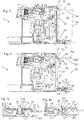
Figures 2 to 4 illustrate a sequence of fastening the tank to the module in the machine ofFig. 1 ; and -
Figs 2a to 4a illustrate an enlarged view of a detail ofFigs 2 to 4 showing the pair formed of the support surface and the resilient member of part of the fastening arrangements. -
Figures 1 to 4a illustrates an exemplary embodiment of abeverage machine 1 according to the invention. -
Machine 1 includes: abeverage processing module 10 having aliquid inlet 11 and amodule fastening arrangement liquid supply tank 30 having aliquid outlet 31 and atank fastening arrangement tank 30 for supplying water. -
Tank outlet 31 can be fluidically connected tomodule inlet 11 and disconnected therefrom, as illustrated inFigs 2a to 4a . - Fastening
arrangements female connector 12 and amale connector 32 cooperating withfemale connector 12 for reversibly assemblingmodule 10 andtank 30. For instance, amale tank connector 32 cooperates with afemale module connector 12 or a male module connector cooperates with a female tank connector. SeeFigs 1a, 2 ,3 and 4 .Tank 30 can have a pivot area 30' about whichtank 30 is pivoted into and out of a fastening position in whichtank 30 andmodule 10 are fastened together via thefastening arrangement Figs 2a ,3a and 4a . - Fastening
arrangements support surface resilient member male connector 32 intofemale connector 12 so as to fasten thetank 30 to the module. For instance, the pair comprises asmodule support surface 13 and a tankresilient member 33 or atank support surface 35 and a moduleresilient member 15. - Female and
male connectors tank 30 is assembled tomodule 10, such degree(s) of freedom F1,F2 being in general opposition to a direction U into whichtank 30 is urged byresilient member support surface Fig. 4 . - At least one of such pair can be made of a
support surface resilient member tank 30 is assembled tomodule 10. -
Support surface 35 may form an outer face oftank 30 andresilient member 15 may form a support arm or panel, such as a foot, projecting from a main body 10' ofmodule 10 and extending acrosstank 30 atouter face 35. For instance, such support arm or panel can extend across a predominant part of thetank 30 atouter face 35. SeeFigs. 2a ,3a and 4a . - The support surface can form an outer face of the module and the resilient member can form a support arm or panel, such as a foot, projecting from a main body of the tank and extending across the module at the outer face. For instance, such support arm or panel may extend across a predominant part of the module at the outer face.
- At least one of such pair can be made of a
support surface 13 and aresilient member 33 configured to urge apart atsupport surface 13 and resilient member 33: anouter face 34 oftank 30 and anouter face 14 ofmodule 10 that facesouter tank face 34. -
Resilient member 33 may include an urgingelement 331, such as aram 331 mounted on a spring 332, movably mounted at one 34 ofouter faces Support surface 13 can be fixedly or integrally or movably mounted at the other 14 ofouter faces Figs. 2a ,3a and 4a . -
Resilient member 33 can be movably mounted to or inoutlet 31 andsupport surface 13 can be fixedly or integrally or movably mounted in or toinlet 11. SeeFigs. 2a ,3a and 4a . - Resilient member may be movably mounted to or in the inlet and support surface may be fixedly or integrally or movably mounted in or to the outlet.
-
Resilient member 33 andsupport surface 13 can be formed as or within a male-female mechanical connection arrangement betweenmodule 10 andtank 30, e.g. a mechanical connection formed byinlet 11 andoutlet 31. SeeFigs. 2a ,3a and 4a . -
Female connector 12 can be formed as a recessed part andmale connector 32 can be formed as a protruding part having a shape generally complementary to the recessed part. -
Female connector 12 andmale connector 32 can be formed as a hook part and a catch part. SeeFigs 1a, 2 and4 . -
Machine 1 can include alid 36 at an opening 36' oftank 30. SeeFigs 1, 1a and 2 .Lid 36 may be moved between a position covering opening 36' and a position uncovering opening 36'. For instance,lid 36 andtank 30 have a fastening arrangement for fasteninglid 36 in the covering position. For example, such lid-tank fastening arrangement includes lid flange 361' projecting and fastened in or around a tank rim 361' delimiting opening 36' and/or a lid and a tank in a hook and hook-retainer configuration, whenlid 36 is in the covering position. -
Lid 36 can be permanently or temporarily assembled totank 30.Lid 36 may include one 32 offemale connector 12 andmale connector 32 for cooperating with the other 32 offemale connector 12 andmale connector 32 comprised bymodule 10 so as to fastentank 30 withlid 36 tomodule 10. -
Male connector 32 can be formed by a hinge oflid 36 and/or by a hinge holder oftank 30, e.g. end portions of the hinge or hinge holder. SeeFigs 1, 1a and4 . - Female and male connectors can be assembled by moving the lid, e.g. pivoting the lid, from the open to the closed position and being disassembled by moving the lid, e.g. pivoting the lid, from the closed to the open position.
-
Tank 30 can include anupright wall 37 delimiting a liquid storage cavity, an outside face ofupright wall 37 forming or being fixed to one 32 offemale connector 12 andmale connector 32 for cooperating with the other 12 offemale connector 12 andmale connector 32. For instance, the other 12 offemale connector 12 andmale connector 32 is formed or fixed to an outside face of anupright wall 17 ofmodule 10. - Female and
male connectors tank 30 and said at least onepair tank 30 whentank 30 is assembled tomodule 10. SeeFig. 4 . -
Female connector 12 andmale connector 32 may be located at oneface tank 30 and said at least onepair face 34 oftank 30 whentank 30 is assembled tomodule 10. Such anotherface 34 being for instance adjacent to or opposite to said oneface 36,3). For example, such anotherface 34 being a bottom face oftank 30 and such oneface side face 37 or atop face 36 oftank 30. -
Module 10 may include abeverage outlet 20 to whichliquid inlet 11 is fluidically connected. -
Module 10 can have aplatform 19 for supportingtank 30 and or extending under a bottom 35 oftank 30 whentank 30 is assembled tomodule 10. For example,platform 19 comprises the inlet. -
Module 10 may have aningredient inlet 21 for supplying an ingredient, such as an ingredient contained in a capsule, to be processed with liquid fromtank 30 vialiquid inlet 11. -
Module 10 can include asupport 22 for placing a user-recipient, e.g. a cup or a mug, for collecting the beverage delivered byoutlet 20. -
Module 10 may have an actuator, such as ahandle 23 or a motor, for actuatingmodule 10 for receiving in and/or evacuating frommodule 10 an ingredient, such as an ingredient contained in a capsule. -
Module 10 can comprise apump 24 for pumping liquid fromoutlet 31 tobeverage outlet 20. -
Module 10 can include a mixingchamber 25 in fluid connection withinlet 11 andbeverage outlet 20 for mixing liquid with an ingredient such as an ingredient contained in a capsule. For instance, mixingchamber 25 is actuated e.g. by ahandle 23 between an open position for inserting into and/or removing fromchamber 25 the ingredient and a closed position for mixing the ingredient and liquid and for subsequent dispensing viabeverage outlet 20. -
Module 10 can have athermal conditioner 26, such as a heater and/or a cooler, for thermally conditioning liquid supplied frominlet 11 tobeverage outlet 20. -
Module 10 can comprise a machine control unit such as a control unit with a user-interface 27. -
Module 10 can include awaste collector 28, such as a collector of residual liquid and/or residual ingredient e.g. contained in a capsule. For instance,waste collector 28 is removable frommodule 10 for servicing. -
Tank 30 may have a valve 331,332 for allowing a passage of liquid via the tank'soutlet 31 when the tank'soutlet 31 is connected to the module'sinlet 11 and for preventing the passage of liquid via the tank'soutlet 31 when the tank'soutlet 31 is disconnected from the module'sinlet 11. For instance, valve 331,332 forms part of the above at least onepair 33, such as forming the urgingelement 331 and optional spring 332 as mentioned above. -
Tank 30 can have a bottom 34 and one or more peripheralupright sidewalls 37 delimiting aliquid storage cavity 38. -
Tank 30 may have an opening 36' delimited by a rim 361' for filling astorage cavity 38 of the tank with liquid, such as water. -
Tank 30 can have afoot 39 on whichtank 30 can rest when filled with liquid before and/or upon assembly oftank 30 tomodule 10. -
Tank 30 may include apassage 39, e.g. a notch or through-opening, for passing anelectric cord 18 tomodule 10, such as an opening in a foot 39' oftank 30.
Claims (15)
- A beverage machine (1) comprising:- a beverage processing module (10) having a liquid inlet (11) and a module fastening arrangement (12,13,15); and- a liquid supply tank (30) having a liquid outlet (31) and a tank fastening arrangement (32,33,35), e.g. a tank (30) for supplying water,the outlet (31) being fluidically connectable to the inlet (11) and disconnectable therefrom,
the fastening arrangements (12,13,15;32,33,35) comprising a female connector (12) and a male connector (32) cooperating with the female connector (12) for reversibly assembling the module (10) and the tank (30), such as a male tank connector (32) cooperating with a female module connector (12) or a male module connector cooperating with a female tank connector, optionally the tank (30) having a pivot area (30') about which the tank (30) is pivoted into and out of a fastening position in which the tank (30) and the module (10) are fastened together via the fastening arrangement (12,13,15;32,33,35),
the fastening arrangements (12,13,15;32,33,35) further comprising at least one pair of a support surface (13,35) and a resilient member (33,15) cooperating together, such as module support surface (13) and a tank resilient member (33) or a tank support surface (35) and a module resilient member (15),
characterised in that said support surface (13,35) and said resilient member (33,15) cooperate together for urging the male connector (32) into the female connector (12) so as to fasten the tank (30) to the module, optionally the female and male connectors (12,32) having one or more degrees of freedom (F1,F2) when the tank (30) is assembled to the module (10), said degree(s) of freedom (F1,F2) being generally in opposition to a direction (U) into which the tank (30) is urged by the resilient member (33,15) cooperating with the support surface (13,35) . - The machine of claim 1, wherein said at least one pair comprises a support surface (13,35) and a resilient member (33,15) configured to be urged together when the tank (30) is assembled to the module (10).
- The machine of claim 2, wherein said support surface (35) forms an outer face of the tank (30) and said resilient member (15) forms a support arm or panel, such as a foot, projecting from a main body (10') of the module (10) and extending across the tank (30) at the outer face (35), such as across a predominant part of the tank (30) at the outer face (35), or wherein said support surface forms an outer face of the module and said resilient member forms a support arm or panel, such as a foot, projecting from a main body of the tank and extending across the module at the outer face, such as across a predominant part of the module at the outer face.
- The machine of any preceding claim, wherein said at least one pair comprises a support surface (13) and a resilient member (33) configured to urge apart at the support surface (13) and the resilient member (33): an outer face (34) of the tank (30) and an outer face (14) of the module (10) that faces the outer tank face (34).
- The machine of claim 4, wherein said resilient member (33) comprises an urging element (331), such as a ram (331) mounted on a spring (332), movably mounted at one (34) of the outer faces (14,34) and wherein said support surface (13) is fixedly or integrally or movably mounted at the other (14) of the outer faces (14,34).
- The machine of claim 4 or 5, wherein said resilient member (33) is movably mounted to or in said outlet (31) and said support surface (13) is fixedly or integrally or movably mounted in or to said inlet (11) or wherein said resilient member is movably mounted to or in said inlet and said support surface is fixedly or integrally or movably mounted in or to said outlet.
- The machine of any preceding claim, wherein said resilient member (33) and said support surface (13) are formed as or within a male-female mechanical connection arrangement between the module (10) and the tank (30), e.g. a mechanical connection formed by the inlet (11) and the outlet (31).
- The machine of any preceding claim, wherein the female connector (12) is formed as a recessed part and the male connector (32) is formed as a protruding part having a shape generally complementary to the recessed part.
- The machine of any preceding claim, wherein the female connector (12) and the male connector (32) are formed as a hook part and a catch part.
- The machine of any preceding claim, which comprises a lid (36) at an opening (36') of the tank (30) and movable between a position covering the opening and a position uncovering the opening, optionally the lid (36) and the tank (30) having a fastening arrangement for fastening the lid (36) in the covering position, such as a lid flange (361') projecting and fastened in or around a tank rim (361') delimiting the opening (36') and/or a lid and a tank in a hook and hook-retainer configuration when the lid (36) is in the covering position.
- The machine of claim 10, wherein the lid (36) is permanently or temporarily assembled to the tank (30) and wherein the lid (36) comprises one (32) of the female connector (12) and the male connector (12,32) for cooperating with the other (32) of the female connector (12) and the male connector (32) comprised by the module (10) so as to fasten tank (30) with the lid (36) to the module (10), optionally:- the male connector (32) being formed by a hinge of the lid (36) and/or by a hinge holder of the tank (30), e.g. end portions of the hinge or hinge holder; or- the female and male connectors being assembled by moving the lid, e.g. pivoting the lid, from the open to the closed position and being disassembled by moving the lid, e.g. pivoting the lid, from the closed to the open position.
- The machine of any preceding claim, wherein the tank (10) comprises an upright wall (37) delimiting a liquid storage cavity, an outside face of the upright wall (37) forming or being fixed to one (32) of the female connector (12) and the male connector (32) for cooperating with the other (12) of the female connector (12) and the male connector (32), optionally the other (12) of the female connector (12) and the male connector (32) being formed or fixed to an outside face of an upright wall (17) of the module (10).
- The machine of any preceding claim, wherein the female connector (12) and the male connector (32) are located at one end of the tank (30) and wherein said at least one pair (13, 35; 33, 15) is locate at a generally opposite end of the tank (30) when the tank (30) is assembled to the module (10).
- The machine of any preceding claim, wherein the female connector (12) and the male connector (32) are located at one face (36,37) of the tank (30) and wherein said at least one pair (13, 35; 33, 15) is locate at an another face (34) of the tank (30) when the tank (30) is assembled to the module (10), said another face (34) being optionally adjacent to or opposite to said one face (36,37), e.g. said another face (34) being a bottom face of the tank and said one face (36, 37) being a side face (37) or a top face (36) of the tank.
- The machine of any preceding claim, wherein the module (10) comprises a beverage outlet (20) to which the liquid inlet (11) is fluidically connected, optionally the module (10) further comprising at least one of:- a platform (19) for supporting the tank (30) and or extending under a bottom (35) of the tank (30) when the tank (30) is assembled to the module (10), the platform (19) optionally comprising the inlet;- an ingredient inlet (21) for supplying an ingredient, such as an ingredient contained in a capsule, to be processed with liquid from the tank (30) via the liquid inlet (11);- a support (22) for placing a user-recipient, e.g. a cup or a mug, for collecting the beverage delivered by the outlet (20) ;- an actuator, such as a handle (23) or a motor, for actuating the module (10) for receiving in and/or evacuating from the module (10) an ingredient, such as an ingredient contained in a capsule;- a pump (24) for pumping said liquid from the outlet (31) to the beverage outlet (20);- a mixing chamber (25) in fluid connection with the inlet (11) and the beverage outlet (20) for mixing said liquid with an ingredient such as an ingredient contained in a capsule, optionally the mixing chamber (25) is actuated e.g. by a handle (23) between an open position for inserting into and/or removing from the chamber (25) said ingredient and a closed position for mixing said ingredient and liquid for dispensing via the beverage outlet (20);- a thermal conditioner (26), such as a heater and/or a cooler, for thermally conditioning said liquid supplied from the inlet (11) to the beverage outlet (20) ;- a machine control unit such as a control unit with a user-interface (27); and- a waste collector (28), such as a collector of residual liquid and/or residual ingredient e.g. contained in a capsule, optionally the waste collector (28) being removable from the module (10) for servicing,and/or the tank (30) comprising at least one of:- a valve (331,332) for allowing a passage of liquid via the tank's outlet (31) when the tank's outlet (31) is connected to the module's inlet (11) and for preventing the passage of liquid via the tank's outlet (31) when the tank's outlet (31) is disconnected from the module's inlet (11), for instance the valve (331,332) forming part of said at least one pair (33) such as forming said urging element (331) and optional spring (332) according to claim 5;- a bottom (34) and one or more peripheral upright sidewalls (37) delimiting a liquid storage cavity (38);- an opening (36') delimited by a rim (361') for filling a storage cavity (38) of the tank with liquid, such as water;- a foot (39) on which the tank (30) can rest when filled with liquid before and/or upon assembly of the tank (30) to the module (10); and- a passage (39), such as a notch or through-opening, for passing an electric cord (18) to the module (10), such as an opening in a foot (39') of the tank (30).
Applications Claiming Priority (2)
| Application Number | Priority Date | Filing Date | Title |
|---|---|---|---|
| EP15194020 | 2015-11-11 | ||
| PCT/EP2016/077076 WO2017081055A1 (en) | 2015-11-11 | 2016-11-09 | Easy connection of a liquid tank to a beverage machine |
Publications (2)
| Publication Number | Publication Date |
|---|---|
| EP3373779A1 EP3373779A1 (en) | 2018-09-19 |
| EP3373779B1 true EP3373779B1 (en) | 2020-12-23 |
Family
ID=54539948
Family Applications (1)
| Application Number | Title | Priority Date | Filing Date |
|---|---|---|---|
| EP16791629.5A Active EP3373779B1 (en) | 2015-11-11 | 2016-11-09 | Easy connection of a liquid tank to a beverage machine |
Country Status (10)
| Country | Link |
|---|---|
| US (1) | US11284738B2 (en) |
| EP (1) | EP3373779B1 (en) |
| JP (1) | JP6910352B2 (en) |
| CN (1) | CN108348093B (en) |
| AU (1) | AU2016353456B2 (en) |
| CA (1) | CA3001089A1 (en) |
| ES (1) | ES2847752T3 (en) |
| PT (1) | PT3373779T (en) |
| RU (1) | RU2713330C2 (en) |
| WO (1) | WO2017081055A1 (en) |
Families Citing this family (8)
| Publication number | Priority date | Publication date | Assignee | Title |
|---|---|---|---|---|
| TWD198547S (en) * | 2018-03-09 | 2019-07-11 | 瑞士商雀巢製品股份有限公 | Beverage dispenser |
| ECSDI18067810S (en) * | 2018-03-09 | 2018-10-31 | "Drink dispenser" (NESCAFE DOLCE GUSTO) | |
| ECSDI18067780S (en) * | 2018-03-26 | 2018-10-31 | "Drink dispenser" (NESCAFE DOLCE GUSTO) | |
| EP3628195A1 (en) | 2018-09-27 | 2020-04-01 | Société des Produits Nestlé S.A. | Beverage preparation machine with recipient detection |
| CA3113758A1 (en) | 2018-09-27 | 2020-04-02 | Societe Des Produits Nestle S.A. | Adaptive service unit of a beverage machine |
| RU2758622C2 (en) * | 2019-10-14 | 2021-11-01 | Общество с ограниченной ответственностью "ЭР ЛАБ" | Device for automatic water intake with simultaneous weight measurement |
| WO2023057612A1 (en) | 2021-10-08 | 2023-04-13 | Société des Produits Nestlé S.A. | Beverage preparation machine with simple ergonomic opening-closure |
| WO2023061991A1 (en) | 2021-10-13 | 2023-04-20 | Société des Produits Nestlé S.A. | Ergonomic beverage machine |
Family Cites Families (95)
| Publication number | Priority date | Publication date | Assignee | Title |
|---|---|---|---|---|
| CH587647A5 (en) * | 1975-07-11 | 1977-05-13 | Icomag Trust Reg | |
| JPS605871Y2 (en) * | 1979-11-22 | 1985-02-23 | 三洋電機株式会社 | Lid mounting device |
| JPS605888B2 (en) | 1979-11-30 | 1985-02-14 | 株式会社安川電機 | Instantaneous torque detection method for AC motors |
| DE3163997D1 (en) | 1980-10-02 | 1984-07-12 | Ciba Geigy Ag | Hydroquinone derivatives, their preparation and use in photographic materials |
| JPS5799640U (en) * | 1980-12-09 | 1982-06-18 | ||
| DE19504839C1 (en) * | 1995-02-14 | 1996-04-04 | Braun Ag | Cold water supply container for electric coffee filter machine |
| US6459854B1 (en) | 2000-01-24 | 2002-10-01 | Nestec S.A. | Process and module for heating liquid |
| FR2806606B1 (en) * | 2000-03-24 | 2002-10-25 | Moulinex Sa | ELECTRIC COFFEE MACHINE WITH PIVOTING WATER TANK |
| PT1153561E (en) | 2000-05-09 | 2005-09-30 | Nestle Sa | DEVICE FOR EXTRACTION OF A SUBSTANCE |
| PT1208782E (en) | 2000-11-28 | 2004-10-29 | Nestle Sa | PERCOLATION DEVICE |
| DE20105672U1 (en) | 2001-03-31 | 2001-09-13 | Eugster Frismag Ag Romanshorn | Espresso brewing device |
| IL162067A0 (en) | 2002-01-10 | 2005-11-20 | Nestle Sa | Automatic device for the extraction of a substance |
| FR2841116B1 (en) * | 2002-06-19 | 2004-11-26 | Seb Sa | EXPRESSO TYPE COFFEE MAKER WITH REMOVABLE WATER TANK |
| DE60227248D1 (en) | 2002-07-12 | 2008-08-07 | Nestec Sa | Device for heating a liquid |
| JP3974047B2 (en) | 2003-02-04 | 2007-09-12 | 象印マホービン株式会社 | Water tank mounting structure of coffee maker |
| ATE316349T1 (en) | 2003-02-07 | 2006-02-15 | Nestec Sa | LINEAR EXTRACTION MODULE FOR PREPARING A DRINK FROM A CARTRIDGE |
| DE20302410U1 (en) | 2003-02-13 | 2004-06-24 | Nestec S.A. | Capsule magazine unit with capsule magazine unit receiving device, in particular an espresso machine |
| EP1495702A1 (en) | 2003-07-10 | 2005-01-12 | Nestec S.A. | Device for the extraction of a cartridge |
| DK1686879T3 (en) | 2003-11-22 | 2007-11-26 | Nestec Sa | Mobile or portable apparatus with pressurized gas reservoir for the preparation of beverages or similar products |
| US7165488B2 (en) | 2003-12-12 | 2007-01-23 | Keurig, Incorporated | Brew chamber for a single serve beverage brewer |
| EP1634520A1 (en) | 2004-09-13 | 2006-03-15 | Nestec S.A. | Device and method for heating a liquid |
| DE202004020907U1 (en) * | 2004-09-24 | 2006-05-24 | BSH Bosch und Siemens Hausgeräte GmbH | Espresso or coffee pad machine has heater for water pumped from tank and, after heating, into brewing chamber whose outlet has temperature sensor connected to control which switches off pump or heater when temperature rises too far |
| ES2360218T3 (en) | 2004-11-11 | 2011-06-01 | Nestec S.A. | MIXING HEAD SELF-CLEANING TO PRODUCE A MILK BASED MIXTURE AND DRINK PRODUCTION MACHINES UNDERSTANDING SUCH MIXING HEAD. |
| RU2385145C2 (en) | 2005-03-29 | 2010-03-27 | Нестек С.А. | Self-contained drinks proportioner |
| ES2330810T3 (en) | 2005-06-07 | 2009-12-15 | Nestec S.A. | FOAM DISTRIBUTOR WITH MILK VESSEL, DISPOSABLE NOZZLE AND DRIP TRAY DEVICE FOR DIFFERENT HEIGHT CONTAINERS. |
| DE602005021827D1 (en) | 2005-09-20 | 2010-07-22 | Nestec Sa | Thermoblock-based beverage production device with a brewing chamber |
| ES2317123T5 (en) | 2005-09-27 | 2017-05-05 | Nestec S.A. | Extraction module for a beverage production device from capsules |
| DE202006002678U1 (en) | 2006-02-17 | 2006-04-20 | Eugster/Frismag Ag | Coffee machine for preparing a coffee beverage by means of packaged, pre-portioned Kaffeepouches |
| FR2898028B1 (en) | 2006-03-01 | 2008-05-16 | Seb Sa | INFUSING MACHINE COMPRISING A DEVICE FOR EJECTING THE INFUSED PRODUCT |
| US7513192B2 (en) | 2006-03-23 | 2009-04-07 | Keurig, Incorporated | Beverage forming device with opening/closing mechanism for a beverage cartridge receiver |
| DE602006019159D1 (en) | 2006-05-24 | 2011-02-03 | Nestec Sa | Brewing device for capsule with locking mechanism with variable transmission ratio |
| ATE498340T1 (en) | 2006-06-09 | 2011-03-15 | Nestec Sa | MODULAR DRINK MAKING SYSTEM WITH A DOCKING STATION |
| ES2456273T3 (en) | 2006-06-16 | 2014-04-21 | Nestec S.A. | Coating compositions |
| DE602006007698D1 (en) | 2006-07-11 | 2009-08-20 | Nestec Sa | Machine for preparing drinks with functional device and foot construction |
| ATE536777T1 (en) | 2007-05-16 | 2011-12-15 | Nestec Sa | BEVERAGE PRODUCTION MODULE AND METHOD FOR OPERATING A BEVERAGE PRODUCTION MODULE |
| CN201076369Y (en) | 2007-07-24 | 2008-06-25 | 宁波圣开纳电器有限公司 | Tap water coffee maker |
| EP2027798A1 (en) | 2007-08-20 | 2009-02-25 | Nestec S.A. | Beverage production module and method for operating a beverage production module |
| CL2008002963A1 (en) | 2007-10-04 | 2010-01-22 | Nestec Sa | Heating device for a machine for the preparation of liquid food or drink, comprising a thermal unit with a metallic mass, through which the liquid circulates, and accumulates heat and supplies it to the liquid, and has one or more insured electrical components rigidly to the thermal unit; and machine. |
| KR20100065200A (en) | 2007-10-04 | 2010-06-15 | 네스텍 소시에테아노님 | Integrated heater for a beverage preparation device |
| AU2008306060C1 (en) | 2007-10-04 | 2015-08-27 | Société des Produits Nestlé S.A. | Beverage brewing unit |
| EP2070454B1 (en) | 2007-12-12 | 2015-07-15 | Nestec S.A. | Beverage production machines comprising a plurality of core units |
| ES2391160T3 (en) | 2007-12-12 | 2012-11-22 | Nestec S.A. | Capsule or beaker receptacle used for liquid food or beverage machines |
| EP2082669A2 (en) | 2008-01-25 | 2009-07-29 | Nestec S.A. | Hybrid apparatus for preparing beverages |
| ES2430851T3 (en) * | 2008-05-08 | 2013-11-22 | Nestec S.A. | Device for the production of beverages |
| CA2723914C (en) | 2008-05-08 | 2017-05-16 | Nestec S.A. | Setting the level of fill in a cup used with a beverage dispenser |
| EP2296515B1 (en) | 2008-05-28 | 2012-07-18 | Nestec S.A. | Pump for liquid beverage preparation devices |
| JP5671458B2 (en) | 2008-07-09 | 2015-02-18 | ネステク ソシエテ アノニム | Device for filling liquid foods or beverages into containers |
| RU2506876C2 (en) | 2008-07-14 | 2014-02-20 | Нестек С.А. | Water circulation system in beverage preparation device |
| WO2010015427A1 (en) | 2008-08-08 | 2010-02-11 | Nestec S.A. | Beverage machine with carrying handle and configurable appearance & side functions |
| RU2530373C2 (en) | 2008-10-03 | 2014-10-10 | Нестек С.А. | User-friendly interface of beverage preparation machine |
| EP2228633B1 (en) | 2009-03-10 | 2017-07-05 | Nestec S.A. | Optical level detector for a beverage machine |
| PT2410894E (en) | 2009-03-23 | 2014-05-02 | Nestec Sa | Pump mount in a beverage preparation machine |
| CA2760989A1 (en) | 2009-05-06 | 2010-11-11 | Nestec S.A. | Beverage machines with simplified servicing |
| SG178460A1 (en) | 2009-08-19 | 2012-03-29 | Nestec Sa | User-friendly start-up mode of a beverage preparation machine |
| DK2473084T3 (en) | 2009-09-02 | 2013-12-09 | Nestec Sa | BEVERAGE FOR A NETWORK |
| CN102481068B (en) | 2009-09-09 | 2015-12-16 | 雀巢产品技术援助有限公司 | The method of ingredient capsule shortage in prevention beverage machine |
| ES2456616T3 (en) | 2010-01-06 | 2014-04-23 | Nestec S.A. | Vibration resistant water tank of a beverage machine |
| EP2525693B2 (en) * | 2010-01-21 | 2018-01-10 | Nestec S.A. | Beverage machine with removable liquid supply reservoir |
| EP2353469A1 (en) | 2010-02-03 | 2011-08-10 | Nestec S.A. | Beverage preparation machine for large size beverages |
| RU2560323C2 (en) | 2010-03-05 | 2015-08-20 | Нестек С.А. | Pump with reduced vibration |
| BR112012029661B1 (en) | 2010-05-21 | 2020-01-28 | Nestec Sa | machine to prepare a drink |
| ES2464775T3 (en) | 2010-05-21 | 2014-06-04 | Nestec S.A. | Ergonomic handle and user interface |
| EP2571408B1 (en) | 2010-05-21 | 2014-05-21 | Nestec S.A. | Beverage machine with ergonomic water management |
| ES2561669T3 (en) | 2010-06-09 | 2016-02-29 | Nestec S.A. | Ergonomic service installation for a beverage machine |
| AU2011267130B2 (en) | 2010-06-17 | 2015-11-19 | Société des Produits Nestlé S.A. | Fast heat-up of a thermal conditioning device e.g. for coffee machine |
| ES2674876T3 (en) | 2010-07-12 | 2018-07-04 | Nestec S.A. | Cup holder secured for beverage machine |
| CN103118573B (en) | 2010-07-16 | 2016-08-31 | 雀巢产品技术援助有限公司 | The firing equipment improved |
| KR20130095757A (en) | 2010-08-27 | 2013-08-28 | 네스텍 소시에테아노님 | Controlled motorized brewing unit |
| WO2012032019A1 (en) | 2010-09-07 | 2012-03-15 | Nestec S.A. | Ergonomic handle with user-interface |
| BR112013009386A2 (en) | 2010-10-27 | 2016-07-26 | Nestec Sa | beverage machine for different space environments |
| US9795247B2 (en) | 2010-10-27 | 2017-10-24 | Nestec S.A. | Beverage machine with a handy outlet |
| PT2645913E (en) | 2010-12-01 | 2014-07-16 | Nestec Sa | Ergonomic user-interface for motorised ingredient chamber |
| CN103338683B (en) | 2010-12-01 | 2016-08-10 | 雀巢产品技术援助有限公司 | There is the beverage machine of the capsule path of band door |
| RU2013129932A (en) | 2010-12-01 | 2015-01-10 | Нестек С.А. | DRINKING MACHINE WITH A DRINKER |
| CN201977568U (en) * | 2010-12-24 | 2011-09-21 | 博西华电器(江苏)有限公司 | Coffee machine |
| CN103402405B (en) | 2011-01-03 | 2017-05-17 | 雀巢产品技术援助有限公司 | Beverage machine with a cover for an ingredient inlet |
| RU2013147192A (en) | 2011-03-23 | 2015-04-27 | Нестек С.А. | DRINKING MACHINE WITH INSERT COVER FOR INGREDIENT |
| JP5799640B2 (en) | 2011-07-29 | 2015-10-28 | 株式会社村田製作所 | Electrostrictive sensor |
| EP2797465B1 (en) | 2011-12-30 | 2015-07-15 | Nestec S.A. | A multi-system beverage machine |
| RU2617365C9 (en) | 2012-01-13 | 2017-07-04 | Нестек С.А. | Beverage preparation machine for low and high cups |
| PT2802245T (en) | 2012-01-13 | 2017-03-13 | Nestec Sa | Beverage machine with a removable module |
| JP5679223B2 (en) | 2012-01-24 | 2015-03-04 | 株式会社ダイフク | Protrusion prevention mechanism for rack items |
| RU2014138922A (en) | 2012-02-28 | 2016-04-20 | Нестек С.А. | CAPSULE AUTOMATIC BREWER |
| EP2633789A1 (en) | 2012-02-28 | 2013-09-04 | Nestec S.A. | Beverage preparation machine with drop management |
| JP6416081B2 (en) * | 2012-05-23 | 2018-10-31 | コーニンクレッカ フィリップス エヌ ヴェKoninklijke Philips N.V. | Beverage production equipment with two-position water container |
| RU2015116639A (en) | 2012-10-09 | 2016-12-10 | Нестек С.А. | EXTRACTION DEVICE WITH ADJUSTABLE RECEIVER FOR VARIOUS SIZES CAPSULES |
| IN2015DN02496A (en) | 2012-10-09 | 2015-09-11 | Nestec Sa | |
| RU2628716C2 (en) | 2012-10-09 | 2017-08-21 | Нестек С.А. | Machine for preparing beverages |
| WO2014056810A1 (en) | 2012-10-09 | 2014-04-17 | Nestec S.A. | Extraction unit with a shiftable multi-size cartridge receiver |
| CN103767547B (en) * | 2012-10-18 | 2017-11-07 | 苏州工业园区咖乐美电器有限公司 | A kind of water supply installation for beverage machine |
| WO2014060370A1 (en) | 2012-10-19 | 2014-04-24 | Nestec S.A. | Extensible cartridge cage with a lock |
| ES2676459T3 (en) | 2012-12-20 | 2018-07-19 | Nestec S.A. | Double ramp to close a receptacle holder |
| EP2934247B1 (en) | 2012-12-20 | 2018-05-30 | Nestec S.A. | Variable transmission for closing a receptacle holder |
| CN203693321U (en) * | 2014-01-02 | 2014-07-09 | 广东顺德雷蒙电器科技有限公司 | Instant heating type kettle |
| CN203873569U (en) * | 2014-04-29 | 2014-10-15 | 张海龙 | Capsule coffee machine |
-
2016
- 2016-11-09 AU AU2016353456A patent/AU2016353456B2/en active Active
- 2016-11-09 JP JP2018522752A patent/JP6910352B2/en active Active
- 2016-11-09 ES ES16791629T patent/ES2847752T3/en active Active
- 2016-11-09 US US15/774,421 patent/US11284738B2/en active Active
- 2016-11-09 RU RU2018120477A patent/RU2713330C2/en active
- 2016-11-09 CN CN201680064939.1A patent/CN108348093B/en active Active
- 2016-11-09 EP EP16791629.5A patent/EP3373779B1/en active Active
- 2016-11-09 WO PCT/EP2016/077076 patent/WO2017081055A1/en active Application Filing
- 2016-11-09 CA CA3001089A patent/CA3001089A1/en active Pending
- 2016-11-09 PT PT167916295T patent/PT3373779T/en unknown
Non-Patent Citations (1)
| Title |
|---|
| None * |
Also Published As
| Publication number | Publication date |
|---|---|
| CN108348093B (en) | 2020-12-15 |
| CN108348093A (en) | 2018-07-31 |
| JP2018537160A (en) | 2018-12-20 |
| EP3373779A1 (en) | 2018-09-19 |
| RU2713330C2 (en) | 2020-02-04 |
| ES2847752T3 (en) | 2021-08-03 |
| PT3373779T (en) | 2021-02-12 |
| CA3001089A1 (en) | 2017-05-18 |
| US20180317697A1 (en) | 2018-11-08 |
| RU2018120477A (en) | 2019-12-16 |
| WO2017081055A1 (en) | 2017-05-18 |
| US11284738B2 (en) | 2022-03-29 |
| JP6910352B2 (en) | 2021-07-28 |
| AU2016353456A1 (en) | 2018-04-05 |
| RU2018120477A3 (en) | 2019-12-16 |
| AU2016353456B2 (en) | 2022-02-24 |
Similar Documents
| Publication | Publication Date | Title |
|---|---|---|
| EP3373779B1 (en) | Easy connection of a liquid tank to a beverage machine | |
| EP2592980B1 (en) | Secure cup support for beverage machine | |
| AU2015366401B2 (en) | Beverage machine with slidingly connectable cup-support | |
| EP2755537B1 (en) | Clean multi-system beverage machine | |
| EP2755535B1 (en) | Multi-system beverage machine multiple connections | |
| EP2474254A1 (en) | Modular beverage dispensing system | |
| EP2755536B1 (en) | Multi-system beverage machine safe connector | |
| CA2860985A1 (en) | Beverage machine with a removable module | |
| US11744397B2 (en) | Beverage machines with modularity | |
| US20220031112A1 (en) | Adaptive service unit of a beverage machine | |
| AU2022365301A1 (en) | Ergonomic beverage machine | |
| EP3687347B1 (en) | Beverage machines with a removable module |
Legal Events
| Date | Code | Title | Description |
|---|---|---|---|
| STAA | Information on the status of an ep patent application or granted ep patent |
Free format text: STATUS: UNKNOWN |
|
| STAA | Information on the status of an ep patent application or granted ep patent |
Free format text: STATUS: THE INTERNATIONAL PUBLICATION HAS BEEN MADE |
|
| PUAI | Public reference made under article 153(3) epc to a published international application that has entered the european phase |
Free format text: ORIGINAL CODE: 0009012 |
|
| STAA | Information on the status of an ep patent application or granted ep patent |
Free format text: STATUS: REQUEST FOR EXAMINATION WAS MADE |
|
| 17P | Request for examination filed |
Effective date: 20180611 |
|
| AK | Designated contracting states |
Kind code of ref document: A1 Designated state(s): AL AT BE BG CH CY CZ DE DK EE ES FI FR GB GR HR HU IE IS IT LI LT LU LV MC MK MT NL NO PL PT RO RS SE SI SK SM TR |
|
| AX | Request for extension of the european patent |
Extension state: BA ME |
|
| DAV | Request for validation of the european patent (deleted) | ||
| DAX | Request for extension of the european patent (deleted) | ||
| STAA | Information on the status of an ep patent application or granted ep patent |
Free format text: STATUS: EXAMINATION IS IN PROGRESS |
|
| 17Q | First examination report despatched |
Effective date: 20190515 |
|
| RAP1 | Party data changed (applicant data changed or rights of an application transferred) |
Owner name: SOCIETE DES PRODUITS NESTLE S.A. |
|
| GRAP | Despatch of communication of intention to grant a patent |
Free format text: ORIGINAL CODE: EPIDOSNIGR1 |
|
| STAA | Information on the status of an ep patent application or granted ep patent |
Free format text: STATUS: GRANT OF PATENT IS INTENDED |
|
| INTG | Intention to grant announced |
Effective date: 20200713 |
|
| GRAS | Grant fee paid |
Free format text: ORIGINAL CODE: EPIDOSNIGR3 |
|
| GRAA | (expected) grant |
Free format text: ORIGINAL CODE: 0009210 |
|
| STAA | Information on the status of an ep patent application or granted ep patent |
Free format text: STATUS: THE PATENT HAS BEEN GRANTED |
|
| AK | Designated contracting states |
Kind code of ref document: B1 Designated state(s): AL AT BE BG CH CY CZ DE DK EE ES FI FR GB GR HR HU IE IS IT LI LT LU LV MC MK MT NL NO PL PT RO RS SE SI SK SM TR |
|
| REG | Reference to a national code |
Ref country code: GB Ref legal event code: FG4D |
|
| REG | Reference to a national code |
Ref country code: DE Ref legal event code: R096 Ref document number: 602016050286 Country of ref document: DE |
|
| REG | Reference to a national code |
Ref country code: AT Ref legal event code: REF Ref document number: 1346866 Country of ref document: AT Kind code of ref document: T Effective date: 20210115 |
|
| REG | Reference to a national code |
Ref country code: IE Ref legal event code: FG4D |
|
| REG | Reference to a national code |
Ref country code: PT Ref legal event code: SC4A Ref document number: 3373779 Country of ref document: PT Date of ref document: 20210212 Kind code of ref document: T Free format text: AVAILABILITY OF NATIONAL TRANSLATION Effective date: 20210205 |
|
| REG | Reference to a national code |
Ref country code: NL Ref legal event code: FP |
|
| PG25 | Lapsed in a contracting state [announced via postgrant information from national office to epo] |
Ref country code: NO Free format text: LAPSE BECAUSE OF FAILURE TO SUBMIT A TRANSLATION OF THE DESCRIPTION OR TO PAY THE FEE WITHIN THE PRESCRIBED TIME-LIMIT Effective date: 20210323 Ref country code: RS Free format text: LAPSE BECAUSE OF FAILURE TO SUBMIT A TRANSLATION OF THE DESCRIPTION OR TO PAY THE FEE WITHIN THE PRESCRIBED TIME-LIMIT Effective date: 20201223 Ref country code: GR Free format text: LAPSE BECAUSE OF FAILURE TO SUBMIT A TRANSLATION OF THE DESCRIPTION OR TO PAY THE FEE WITHIN THE PRESCRIBED TIME-LIMIT Effective date: 20210324 Ref country code: FI Free format text: LAPSE BECAUSE OF FAILURE TO SUBMIT A TRANSLATION OF THE DESCRIPTION OR TO PAY THE FEE WITHIN THE PRESCRIBED TIME-LIMIT Effective date: 20201223 |
|
| PG25 | Lapsed in a contracting state [announced via postgrant information from national office to epo] |
Ref country code: SE Free format text: LAPSE BECAUSE OF FAILURE TO SUBMIT A TRANSLATION OF THE DESCRIPTION OR TO PAY THE FEE WITHIN THE PRESCRIBED TIME-LIMIT Effective date: 20201223 Ref country code: LV Free format text: LAPSE BECAUSE OF FAILURE TO SUBMIT A TRANSLATION OF THE DESCRIPTION OR TO PAY THE FEE WITHIN THE PRESCRIBED TIME-LIMIT Effective date: 20201223 Ref country code: BG Free format text: LAPSE BECAUSE OF FAILURE TO SUBMIT A TRANSLATION OF THE DESCRIPTION OR TO PAY THE FEE WITHIN THE PRESCRIBED TIME-LIMIT Effective date: 20210323 |
|
| PG25 | Lapsed in a contracting state [announced via postgrant information from national office to epo] |
Ref country code: HR Free format text: LAPSE BECAUSE OF FAILURE TO SUBMIT A TRANSLATION OF THE DESCRIPTION OR TO PAY THE FEE WITHIN THE PRESCRIBED TIME-LIMIT Effective date: 20201223 |
|
| REG | Reference to a national code |
Ref country code: LT Ref legal event code: MG9D |
|
| PG25 | Lapsed in a contracting state [announced via postgrant information from national office to epo] |
Ref country code: RO Free format text: LAPSE BECAUSE OF FAILURE TO SUBMIT A TRANSLATION OF THE DESCRIPTION OR TO PAY THE FEE WITHIN THE PRESCRIBED TIME-LIMIT Effective date: 20201223 Ref country code: SK Free format text: LAPSE BECAUSE OF FAILURE TO SUBMIT A TRANSLATION OF THE DESCRIPTION OR TO PAY THE FEE WITHIN THE PRESCRIBED TIME-LIMIT Effective date: 20201223 Ref country code: SM Free format text: LAPSE BECAUSE OF FAILURE TO SUBMIT A TRANSLATION OF THE DESCRIPTION OR TO PAY THE FEE WITHIN THE PRESCRIBED TIME-LIMIT Effective date: 20201223 Ref country code: LT Free format text: LAPSE BECAUSE OF FAILURE TO SUBMIT A TRANSLATION OF THE DESCRIPTION OR TO PAY THE FEE WITHIN THE PRESCRIBED TIME-LIMIT Effective date: 20201223 Ref country code: CZ Free format text: LAPSE BECAUSE OF FAILURE TO SUBMIT A TRANSLATION OF THE DESCRIPTION OR TO PAY THE FEE WITHIN THE PRESCRIBED TIME-LIMIT Effective date: 20201223 Ref country code: EE Free format text: LAPSE BECAUSE OF FAILURE TO SUBMIT A TRANSLATION OF THE DESCRIPTION OR TO PAY THE FEE WITHIN THE PRESCRIBED TIME-LIMIT Effective date: 20201223 |
|
| REG | Reference to a national code |
Ref country code: ES Ref legal event code: FG2A Ref document number: 2847752 Country of ref document: ES Kind code of ref document: T3 Effective date: 20210803 |
|
| PG25 | Lapsed in a contracting state [announced via postgrant information from national office to epo] |
Ref country code: PL Free format text: LAPSE BECAUSE OF FAILURE TO SUBMIT A TRANSLATION OF THE DESCRIPTION OR TO PAY THE FEE WITHIN THE PRESCRIBED TIME-LIMIT Effective date: 20201223 |
|
| REG | Reference to a national code |
Ref country code: DE Ref legal event code: R097 Ref document number: 602016050286 Country of ref document: DE |
|
| PG25 | Lapsed in a contracting state [announced via postgrant information from national office to epo] |
Ref country code: IS Free format text: LAPSE BECAUSE OF FAILURE TO SUBMIT A TRANSLATION OF THE DESCRIPTION OR TO PAY THE FEE WITHIN THE PRESCRIBED TIME-LIMIT Effective date: 20210423 |
|
| PG25 | Lapsed in a contracting state [announced via postgrant information from national office to epo] |
Ref country code: AL Free format text: LAPSE BECAUSE OF FAILURE TO SUBMIT A TRANSLATION OF THE DESCRIPTION OR TO PAY THE FEE WITHIN THE PRESCRIBED TIME-LIMIT Effective date: 20201223 |
|
| PLBE | No opposition filed within time limit |
Free format text: ORIGINAL CODE: 0009261 |
|
| STAA | Information on the status of an ep patent application or granted ep patent |
Free format text: STATUS: NO OPPOSITION FILED WITHIN TIME LIMIT |
|
| PG25 | Lapsed in a contracting state [announced via postgrant information from national office to epo] |
Ref country code: DK Free format text: LAPSE BECAUSE OF FAILURE TO SUBMIT A TRANSLATION OF THE DESCRIPTION OR TO PAY THE FEE WITHIN THE PRESCRIBED TIME-LIMIT Effective date: 20201223 |
|
| 26N | No opposition filed |
Effective date: 20210924 |
|
| PG25 | Lapsed in a contracting state [announced via postgrant information from national office to epo] |
Ref country code: SI Free format text: LAPSE BECAUSE OF FAILURE TO SUBMIT A TRANSLATION OF THE DESCRIPTION OR TO PAY THE FEE WITHIN THE PRESCRIBED TIME-LIMIT Effective date: 20201223 |
|
| PG25 | Lapsed in a contracting state [announced via postgrant information from national office to epo] |
Ref country code: IS Free format text: LAPSE BECAUSE OF FAILURE TO SUBMIT A TRANSLATION OF THE DESCRIPTION OR TO PAY THE FEE WITHIN THE PRESCRIBED TIME-LIMIT Effective date: 20210423 |
|
| PG25 | Lapsed in a contracting state [announced via postgrant information from national office to epo] |
Ref country code: MC Free format text: LAPSE BECAUSE OF FAILURE TO SUBMIT A TRANSLATION OF THE DESCRIPTION OR TO PAY THE FEE WITHIN THE PRESCRIBED TIME-LIMIT Effective date: 20201223 |
|
| PG25 | Lapsed in a contracting state [announced via postgrant information from national office to epo] |
Ref country code: LU Free format text: LAPSE BECAUSE OF NON-PAYMENT OF DUE FEES Effective date: 20211109 |
|
| PG25 | Lapsed in a contracting state [announced via postgrant information from national office to epo] |
Ref country code: IE Free format text: LAPSE BECAUSE OF NON-PAYMENT OF DUE FEES Effective date: 20211109 |
|
| PGFP | Annual fee paid to national office [announced via postgrant information from national office to epo] |
Ref country code: CH Payment date: 20221201 Year of fee payment: 7 Ref country code: BE Payment date: 20221019 Year of fee payment: 7 |
|
| PG25 | Lapsed in a contracting state [announced via postgrant information from national office to epo] |
Ref country code: HU Free format text: LAPSE BECAUSE OF FAILURE TO SUBMIT A TRANSLATION OF THE DESCRIPTION OR TO PAY THE FEE WITHIN THE PRESCRIBED TIME-LIMIT; INVALID AB INITIO Effective date: 20161109 |
|
| PG25 | Lapsed in a contracting state [announced via postgrant information from national office to epo] |
Ref country code: CY Free format text: LAPSE BECAUSE OF FAILURE TO SUBMIT A TRANSLATION OF THE DESCRIPTION OR TO PAY THE FEE WITHIN THE PRESCRIBED TIME-LIMIT Effective date: 20201223 |
|
| P01 | Opt-out of the competence of the unified patent court (upc) registered |
Effective date: 20230623 |
|
| PGFP | Annual fee paid to national office [announced via postgrant information from national office to epo] |
Ref country code: NL Payment date: 20231016 Year of fee payment: 8 Ref country code: FR Payment date: 20230929 Year of fee payment: 8 |
|
| PGFP | Annual fee paid to national office [announced via postgrant information from national office to epo] |
Ref country code: GB Payment date: 20231006 Year of fee payment: 8 |
|
| PGFP | Annual fee paid to national office [announced via postgrant information from national office to epo] |
Ref country code: ES Payment date: 20231211 Year of fee payment: 8 |
|
| PGFP | Annual fee paid to national office [announced via postgrant information from national office to epo] |
Ref country code: PT Payment date: 20231107 Year of fee payment: 8 Ref country code: IT Payment date: 20231010 Year of fee payment: 8 Ref country code: DE Payment date: 20230929 Year of fee payment: 8 Ref country code: AT Payment date: 20231025 Year of fee payment: 8 |
|
| PGFP | Annual fee paid to national office [announced via postgrant information from national office to epo] |
Ref country code: BE Payment date: 20231016 Year of fee payment: 8 |