EP1447034A1 - Capsule magazine unit having a holding device for the capsule magazine unit, in particular of an espresso machine - Google Patents
Capsule magazine unit having a holding device for the capsule magazine unit, in particular of an espresso machine Download PDFInfo
- Publication number
- EP1447034A1 EP1447034A1 EP04001915A EP04001915A EP1447034A1 EP 1447034 A1 EP1447034 A1 EP 1447034A1 EP 04001915 A EP04001915 A EP 04001915A EP 04001915 A EP04001915 A EP 04001915A EP 1447034 A1 EP1447034 A1 EP 1447034A1
- Authority
- EP
- European Patent Office
- Prior art keywords
- magazine unit
- capsule magazine
- capsule
- holding device
- locking
- Prior art date
- Legal status (The legal status is an assumption and is not a legal conclusion. Google has not performed a legal analysis and makes no representation as to the accuracy of the status listed.)
- Granted
Links
- 239000002775 capsule Substances 0.000 title claims abstract description 225
- 235000015114 espresso Nutrition 0.000 title claims abstract description 17
- 235000013353 coffee beverage Nutrition 0.000 claims abstract description 22
- 238000003780 insertion Methods 0.000 description 5
- 230000037431 insertion Effects 0.000 description 5
- 230000007246 mechanism Effects 0.000 description 4
- 238000006073 displacement reaction Methods 0.000 description 2
- 230000005484 gravity Effects 0.000 description 2
- 230000000694 effects Effects 0.000 description 1
- 230000000284 resting effect Effects 0.000 description 1
- 239000000126 substance Substances 0.000 description 1
Images


Classifications
-
- A—HUMAN NECESSITIES
- A47—FURNITURE; DOMESTIC ARTICLES OR APPLIANCES; COFFEE MILLS; SPICE MILLS; SUCTION CLEANERS IN GENERAL
- A47F—SPECIAL FURNITURE, FITTINGS, OR ACCESSORIES FOR SHOPS, STOREHOUSES, BARS, RESTAURANTS OR THE LIKE; PAYING COUNTERS
- A47F1/00—Racks for dispensing merchandise; Containers for dispensing merchandise
- A47F1/04—Racks or containers with arrangements for dispensing articles, e.g. by means of gravity or springs
- A47F1/08—Racks or containers with arrangements for dispensing articles, e.g. by means of gravity or springs dispensing from bottom
- A47F1/085—Racks or containers with arrangements for dispensing articles, e.g. by means of gravity or springs dispensing from bottom for nested articles, e.g. cups, cones
-
- A—HUMAN NECESSITIES
- A47—FURNITURE; DOMESTIC ARTICLES OR APPLIANCES; COFFEE MILLS; SPICE MILLS; SUCTION CLEANERS IN GENERAL
- A47J—KITCHEN EQUIPMENT; COFFEE MILLS; SPICE MILLS; APPARATUS FOR MAKING BEVERAGES
- A47J31/00—Apparatus for making beverages
- A47J31/24—Coffee-making apparatus in which hot water is passed through the filter under pressure, i.e. in which the coffee grounds are extracted under pressure
- A47J31/34—Coffee-making apparatus in which hot water is passed through the filter under pressure, i.e. in which the coffee grounds are extracted under pressure with hot water under liquid pressure
- A47J31/36—Coffee-making apparatus in which hot water is passed through the filter under pressure, i.e. in which the coffee grounds are extracted under pressure with hot water under liquid pressure with mechanical pressure-producing means
- A47J31/3604—Coffee-making apparatus in which hot water is passed through the filter under pressure, i.e. in which the coffee grounds are extracted under pressure with hot water under liquid pressure with mechanical pressure-producing means with a mechanism arranged to move the brewing chamber between loading, infusing and ejecting stations
- A47J31/3623—Cartridges being employed
- A47J31/3642—Cartridge magazines therefor
Definitions
- the invention relates to a capsule magazine unit having a holding device for the capsule magazine unit, into which the capsule magazine unit can be releasably inserted, in particular of an espresso machine.
- Capsule magazine units of this type are already known, for instance in DE 200 159 03 U1, in order to keep capsules having the substance which is to be prepared, in particular different types of espresso coffee, ready in an organized and easily selectable manner.
- a plurality of capsule magazine tubes can be arranged in the shape of a circular ring or else in a linear row as the capsule magazine unit.
- the capsule magazine unit is preferably a releasable part of an espresso machine, but may also be formed separately from the latter.
- the capsule magazine unit can be removed from the holding device for the capsule magazine unit for convenient fitting with the different coffee capsules and can then be re-inserted into it.
- Each capsule magazine tube which is part of the capsule magazine unit has a lower capsule removal opening which is arranged laterally or radially outwards if the capsule magazine tubes are arranged in a circle.
- the lowermost capsule can be removed in each case manually from this capsule removal opening or - preferably if the holding device for the capsule magazine unit is integrated in an espresso machine - can be pushed out of the capsule removal opening by mechanical means in order to convey it into a brewing position to prepare the espresso.
- the capsule magazine units have made great progress in the simple and reliable preparation of drinks, in particular the preparation of espresso, it can be perceived as being a drawback that, when the capsule magazine unit has been removed from the holding device for the capsule magazine unit, in particular of an espresso machine, the capsules may unintentionally slide out of the removal openings of the magazine tubes, in particular if the capsule magazine unit is tilted.
- the present invention is based on the object of therefore developing a capsule magazine unit of the generic type mentioned at the beginning with the effect that the sliding of capsules out of the capsule magazine tubes of the capsule magazine unit which has been removed from the holding device for the capsule magazine unit is reliably avoided without complicating the handling.
- the technical means in order to achieve this are to be uncomplicated in terms of design.
- a locking ring is essential in order to prevent coffee capsules from falling out of the lateral capsule removal openings of the capsule magazine unit, the said locking ring, if the capsule magazine tubes are orientated vertically (as is customary), therefore likewise being displaceable vertically in the direction of these tubes.
- the said locking ring In a lower locking position, into which it automatically slides as a consequence of gravity if the capsule magazine unit has been removed from the holding device for the capsule magazine unit, the said locking ring covers the capsule removal openings of the capsule magazine tubes to an extent sufficient for them no longer to be able to fall out of the capsule removal opening.
- the essential means furthermore include at least one locking-ring lifting element which is designed in particular as a simple lug.
- the locking-ring lifting element causes the locking ring to be blocked relative to the sliding-down capsule magazine unit, which means that it reaches an upper release position in relation to the capsule removal opening, so that a lower capsule for preparing drinks can be removed in each case from the capsule removal opening.
- the shape of the locking ring is in principle as desired and is matched to the arrangement of the magazine tubes, so that their capsule removal openings can be essentially covered in the lower locking position of the locking ring and, on the other hand, the locking ring can be displaced along the capsule magazine tubes.
- the locking ring is simply of circular-ring-shaped design.
- the said locking ring needs merely to rest linearly on the said tubes. The friction during displacement is therefore small.
- the locking-ring lifting element can be at least one simple, passive element which, in particular according to Claim 5, is a lug protruding inwards on the capsule magazine unit opening of the holding device for the capsule magazine unit.
- the locking-ring lifting element is integrated in the locking ring, for example as a lug which projects outwards from the locking ring or as an outer collar or by dimensioning the external diameter of the locking ring in relation to the capsule magazine unit opening in the holding device for the capsule magazine unit.
- the first variant of the capsule magazine unit according to Claim 5 has the features of the capsule magazine unit having a base on which the locking ring rests when the capsule magazine unit has been removed from the holding device for the capsule magazine unit, of at least one lug protruding essentially inwards into the holding device for the capsule magazine unit as the locking-ring lifting element on which the locking ring rests when the capsule magazine unit has been inserted into the holding device for the capsule magazine unit, and of the base of the capsule magazine unit having at least one outwardly open slot through which the lug of the holding device for the capsule magazine unit can pass when the capsule magazine unit is pulled vertically out of the holding device for the capsule magazine unit.
- the base of the capsule magazine unit delimits the lower locking position into which the locking ring normally wants to move.
- its release position is only reached if the capsule magazine unit is inserted into the holding device for the capsule magazine unit and is lowered onto the lug.
- the locking ring is held above the capsule removal openings on the lug of the magazine holding device.
- one lug is sufficient for holding back and supporting the locking ring
- the arrangement of at least two, preferably more lugs at a distance from one another is advantageous, so that the locking ring resting on them does not tilt.
- Coordinated with them, according to Claim 6, are a plurality of slots offset at a distance around the circumference of the base from the base of the capsule magazine unit, which base is round to give a circular arrangement of a plurality of capsule magazine tubes, so that the base can be lowered past the lugs.
- the slots are arranged in the base in such a manner that, in every possible operational capsule removal position of the capsule magazine unit, the latter can be pulled out without rotation in the holding device for the capsule magazine unit, by corresponding slots being vertically aligned with all of the lugs.
- the capsule magazine unit according to Claim 8 can have, at a vertical distance above the capsule removal openings, an upper stop which upwardly secures the locking ring against sliding out of the capsule magazine unit.
- the stop can comprise a circular-ring-shaped collar of the capsule magazine unit at a sufficient distance above the capsule removal openings.
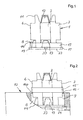
- the capsule magazine unit referred to in general by 1 in Figures 1 and 3 comprises six essentially cylindrical capsule magazine tubes which are vertical in the operational position and are fitted in a circular arrangement on a round base 23.
- Each capsule magazine tube e.g. 6, has a capsule removal opening, e.g. 8, at the bottom above the base 23, the said opening being directed radially outwards with respect to a main axis (not shown) of the capsule magazine unit, so that the respectively lowermost of the coffee capsules stacked in the capsule magazine tube can be pushed out of the capsule magazine tube 6 at the capsule removal opening 8.
- a capsule removal opening e.g. 8
- the capsule magazine unit 1 can be inserted in the operational position into a holding device 9 for the capsule magazine unit as part of an espresso machine body 10
- use is made of mechanical means (not illustrated in the drawing) which automatically remove the coffee capsule from a capsule magazine tube, which is rotated into a removal position, and convey this coffee capsule to a brewing position.
- the capsule magazine unit is removed preferably from the holding device 9 for the capsule magazine unit, or from the espresso machine body 10 in order to be filled away from it.
- the coffee capsules are introduced into insertion mechanisms, e.g. 11, formed at the top of the capsule magazine tubes, and are stacked in the capsule magazine tubes.
- the insertion mechanisms are matched for this purpose to the essentially truncated-cylinder shape of the coffee capsules, so that the coffee capsules can be stacked only in the desired orientation with the base downwards.
- the coffee capsules which can be seen in Figures 1 and 2 are referred to by 12 to 14.
- the capsule magazine unit 1 is preferably filled with coffee capsules only to an extent such that it is not possible for any coffee capsule, such as here the coffee capsule 12, to slide laterally counter to the insertion direction out of the insertion mechanism.
- a circular-ring-shaped, vertically displaceable locking ring 15 is provided around the capsule magazine unit.
- the internal diameter of the locking ring is of sufficient size that the locking ring bears in a slideable manner against outer surface lines of the capsule magazine tubes 2 to 7. It is therefore guided by the capsule magazine tubes 2 to 7.
- additional guide means (which are not shown in the drawing) may be provided in the region of the capsule removal openings.
- the locking ring 15 In the lower locking position of the locking ring 15, which position is illustrated in Figure 1 and may also be referred to as the retaining position since the coffee capsules, e.g. 13, 14, are held back in it against sliding out of the magazine tubes, the locking ring 15 rests on the base 23 of the capsule magazine unit. Without further actuating means, it is able to slide downwards onto the base only by means of gravity.
- the locking ring 15 passes from the lower locking position into an upper release position with respect to the capsule removal openings 8 by the capsule magazine unit 1 simply being introduced correctly from above into the holding device 9 for the capsule magazine unit, as illustrated in Figure 2, in which the locking ring is in the release position. It is held in the release position by locking-ring lifting elements 16, 16a which are orientated inwards towards the vertical main axis (not illustrated) of the holding device 9 for the capsule magazine unit or of the capsule magazine unit 1 inserted therein.
- the locking-ring lifting elements are arranged at equal distances in the circumferential direction of an upper holding opening (not designated) of the holding device 9 for the capsule magazine unit and are therefore suitable for holding the locking ring 15 in an untilted manner.
- slots 17 to 22 on the edge of the base 23 is matched, according to Figure 3, to the configuration of the locking-ring lifting elements.
- the slots are shaped from the base in such a manner that they permit the base to pass by the locking-ring lifting elements, e.g. 15, 16, when the capsule magazine unit 1 is inserted into the holding device 9 for the capsule magazine unit or is removed therefrom, specifically by a simple vertical movement during removal from any possible operational capsule removal position or latching position of the capsule magazine unit.
- an upper stop which prevents the locking ring 15 from unintentionally sliding out upwards over the capsule magazine tubes 2 to 7, so that the locking ring cannot be lost.
- the base 23 of the capsule magazine unit 1 rests on a base support 24 in the espresso machine body 10, which support can be designed as a revolving magazine drawer and as such is described, for example, in PCT/EP 02/03281 by the applicant.
- the embodiment of the second variant according to Figures 4 and 5 is distinguished by the fact that the locking-ring lifting elements 26-29 protrude from the outer edge of the locking ring 25, specifically the four locking-ring lifting elements, which are designed as lugs, protrude here uniformly over the circumference without being allocated to a capsule removal position or latching position of the capsule magazine unit 1a.
Landscapes
- Engineering & Computer Science (AREA)
- Mechanical Engineering (AREA)
- Food Science & Technology (AREA)
- Apparatus For Making Beverages (AREA)
- External Artificial Organs (AREA)
Abstract
Description
- The invention relates to a capsule magazine unit having a holding device for the capsule magazine unit, into which the capsule magazine unit can be releasably inserted, in particular of an espresso machine.
- Capsule magazine units of this type are already known, for instance in DE 200 159 03 U1, in order to keep capsules having the substance which is to be prepared, in particular different types of espresso coffee, ready in an organized and easily selectable manner. Accordingly, a plurality of capsule magazine tubes can be arranged in the shape of a circular ring or else in a linear row as the capsule magazine unit. The capsule magazine unit is preferably a releasable part of an espresso machine, but may also be formed separately from the latter. The capsule magazine unit can be removed from the holding device for the capsule magazine unit for convenient fitting with the different coffee capsules and can then be re-inserted into it. Each capsule magazine tube which is part of the capsule magazine unit has a lower capsule removal opening which is arranged laterally or radially outwards if the capsule magazine tubes are arranged in a circle. The lowermost capsule can be removed in each case manually from this capsule removal opening or - preferably if the holding device for the capsule magazine unit is integrated in an espresso machine - can be pushed out of the capsule removal opening by mechanical means in order to convey it into a brewing position to prepare the espresso.
- Although the capsule magazine units have made great progress in the simple and reliable preparation of drinks, in particular the preparation of espresso, it can be perceived as being a drawback that, when the capsule magazine unit has been removed from the holding device for the capsule magazine unit, in particular of an espresso machine, the capsules may unintentionally slide out of the removal openings of the magazine tubes, in particular if the capsule magazine unit is tilted.
- The present invention is based on the object of therefore developing a capsule magazine unit of the generic type mentioned at the beginning with the effect that the sliding of capsules out of the capsule magazine tubes of the capsule magazine unit which has been removed from the holding device for the capsule magazine unit is reliably avoided without complicating the handling. The technical means in order to achieve this are to be uncomplicated in terms of design.
- This object is achieved by the invention specified in
Claims - The features according to the invention are furthermore revealed in detail in
Claim 3. - In both variants of the invention, a locking ring is essential in order to prevent coffee capsules from falling out of the lateral capsule removal openings of the capsule magazine unit, the said locking ring, if the capsule magazine tubes are orientated vertically (as is customary), therefore likewise being displaceable vertically in the direction of these tubes. In a lower locking position, into which it automatically slides as a consequence of gravity if the capsule magazine unit has been removed from the holding device for the capsule magazine unit, the said locking ring covers the capsule removal openings of the capsule magazine tubes to an extent sufficient for them no longer to be able to fall out of the capsule removal opening. The essential means furthermore include at least one locking-ring lifting element which is designed in particular as a simple lug.
- When the capsule magazine unit - as a rule filled with coffee capsules - is inserted into the holding device for the capsule magazine unit, the locking-ring lifting element causes the locking ring to be blocked relative to the sliding-down capsule magazine unit, which means that it reaches an upper release position in relation to the capsule removal opening, so that a lower capsule for preparing drinks can be removed in each case from the capsule removal opening.
- Special handling of the locking ring is therefore not required. On the contrary, its locking or retaining function for the separated capsule magazine unit occurs automatically, as does the release of the capsule removal openings when the capsule magazine unit is introduced into the holding device for the capsule magazine unit.
- The shape of the locking ring is in principle as desired and is matched to the arrangement of the magazine tubes, so that their capsule removal openings can be essentially covered in the lower locking position of the locking ring and, on the other hand, the locking ring can be displaced along the capsule magazine tubes.
- In the case of a particularly expedient, circular arrangement of the capsule magazine tubes, the locking ring is simply of circular-ring-shaped design. For guidance purposes during the vertical displacement with respect to the capsule magazine tubes, the said locking ring needs merely to rest linearly on the said tubes. The friction during displacement is therefore small.
- The device is also uncomplicated because the locking-ring lifting element can be at least one simple, passive element which, in particular according to Claim 5, is a lug protruding inwards on the capsule magazine unit opening of the holding device for the capsule magazine unit. In the second variant according to
Claims - More specifically, the first variant of the capsule magazine unit according to Claim 5 has the features of the capsule magazine unit having a base on which the locking ring rests when the capsule magazine unit has been removed from the holding device for the capsule magazine unit, of at least one lug protruding essentially inwards into the holding device for the capsule magazine unit as the locking-ring lifting element on which the locking ring rests when the capsule magazine unit has been inserted into the holding device for the capsule magazine unit, and of the base of the capsule magazine unit having at least one outwardly open slot through which the lug of the holding device for the capsule magazine unit can pass when the capsule magazine unit is pulled vertically out of the holding device for the capsule magazine unit. In this case, the base of the capsule magazine unit delimits the lower locking position into which the locking ring normally wants to move. In contrast, its release position is only reached if the capsule magazine unit is inserted into the holding device for the capsule magazine unit and is lowered onto the lug. In this case, the locking ring is held above the capsule removal openings on the lug of the magazine holding device.
- Although, in principle, one lug is sufficient for holding back and supporting the locking ring, the arrangement of at least two, preferably more lugs at a distance from one another is advantageous, so that the locking ring resting on them does not tilt. Coordinated with them, according to
Claim 6, are a plurality of slots offset at a distance around the circumference of the base from the base of the capsule magazine unit, which base is round to give a circular arrangement of a plurality of capsule magazine tubes, so that the base can be lowered past the lugs. In particular, the slots are arranged in the base in such a manner that, in every possible operational capsule removal position of the capsule magazine unit, the latter can be pulled out without rotation in the holding device for the capsule magazine unit, by corresponding slots being vertically aligned with all of the lugs. - In contrast, in the second variant of the invention according to
Claims - In addition, in both variants, the capsule magazine unit according to
Claim 8 can have, at a vertical distance above the capsule removal openings, an upper stop which upwardly secures the locking ring against sliding out of the capsule magazine unit. The stop can comprise a circular-ring-shaped collar of the capsule magazine unit at a sufficient distance above the capsule removal openings. - A respective exemplary embodiment of both variants of the invention will be explained below with reference to a drawing having five figures, in which:
- Figure 1
- shows a side view of a capsule magazine unit of the first variant, which unit is designed as a rotary magazine,
- Figure 2
- shows the capsule magazine unit according to Figure 1, but when it is inserted into a holding device for the capsule magazine unit, as part of an espresso machine body,
- Figure 3
- shows a plan view of the capsule magazine unit when detached from the holding device for the capsule magazine unit according to Figure 1,
- Figure 4
- shows a capsule magazine unit of the second variant when inserted into the holding device for the capsule magazine unit, and
- Figure 5
- shows the capsule magazine unit according to Figure 4 when detached, in a plan view.
- In both variants, corresponding features are provided with the same reference numbers.
- The capsule magazine unit referred to in general by 1 in Figures 1 and 3 comprises six essentially cylindrical capsule magazine tubes which are vertical in the operational position and are fitted in a circular arrangement on a
round base 23. - Each capsule magazine tube, e.g. 6, has a capsule removal opening, e.g. 8, at the bottom above the
base 23, the said opening being directed radially outwards with respect to a main axis (not shown) of the capsule magazine unit, so that the respectively lowermost of the coffee capsules stacked in the capsule magazine tube can be pushed out of thecapsule magazine tube 6 at the capsule removal opening 8. For this purpose, in the present exemplary embodiment, since thecapsule magazine unit 1 can be inserted in the operational position into a holding device 9 for the capsule magazine unit as part of anespresso machine body 10, use is made of mechanical means (not illustrated in the drawing) which automatically remove the coffee capsule from a capsule magazine tube, which is rotated into a removal position, and convey this coffee capsule to a brewing position. - In order to fill the capsule magazine unit with coffee capsules of certain types of espresso coffee, which capsules are sorted for the different
capsule magazine tubes 2 to 7, the capsule magazine unit is removed preferably from the holding device 9 for the capsule magazine unit, or from theespresso machine body 10 in order to be filled away from it. For this purpose, the coffee capsules are introduced into insertion mechanisms, e.g. 11, formed at the top of the capsule magazine tubes, and are stacked in the capsule magazine tubes. The insertion mechanisms are matched for this purpose to the essentially truncated-cylinder shape of the coffee capsules, so that the coffee capsules can be stacked only in the desired orientation with the base downwards. The coffee capsules which can be seen in Figures 1 and 2 are referred to by 12 to 14. Thecapsule magazine unit 1 is preferably filled with coffee capsules only to an extent such that it is not possible for any coffee capsule, such as here thecoffee capsule 12, to slide laterally counter to the insertion direction out of the insertion mechanism. - In order to avoid an undesirable sliding of the lower coffee capsules, e.g. 12, 13, out of the capsule removal openings, e.g. 8, if the detached
capsule magazine unit 1 is held at an inclination, a circular-ring-shaped, verticallydisplaceable locking ring 15 is provided around the capsule magazine unit. The internal diameter of the locking ring is of sufficient size that the locking ring bears in a slideable manner against outer surface lines of thecapsule magazine tubes 2 to 7. It is therefore guided by thecapsule magazine tubes 2 to 7. Particularly if the locking ring has a smaller vertical extent than the height of thecapsule removal openings 8, additional guide means (which are not shown in the drawing) may be provided in the region of the capsule removal openings. - In the lower locking position of the
locking ring 15, which position is illustrated in Figure 1 and may also be referred to as the retaining position since the coffee capsules, e.g. 13, 14, are held back in it against sliding out of the magazine tubes, thelocking ring 15 rests on thebase 23 of the capsule magazine unit. Without further actuating means, it is able to slide downwards onto the base only by means of gravity. - Without special manual actuation, the
locking ring 15 passes from the lower locking position into an upper release position with respect to thecapsule removal openings 8 by thecapsule magazine unit 1 simply being introduced correctly from above into the holding device 9 for the capsule magazine unit, as illustrated in Figure 2, in which the locking ring is in the release position. It is held in the release position by locking-ring lifting elements capsule magazine unit 1 inserted therein. The locking-ring lifting elements are arranged at equal distances in the circumferential direction of an upper holding opening (not designated) of the holding device 9 for the capsule magazine unit and are therefore suitable for holding thelocking ring 15 in an untilted manner. - The arrangement of
slots 17 to 22 on the edge of thebase 23 is matched, according to Figure 3, to the configuration of the locking-ring lifting elements. In detail, the slots are shaped from the base in such a manner that they permit the base to pass by the locking-ring lifting elements, e.g. 15, 16, when thecapsule magazine unit 1 is inserted into the holding device 9 for the capsule magazine unit or is removed therefrom, specifically by a simple vertical movement during removal from any possible operational capsule removal position or latching position of the capsule magazine unit. - Not illustrated on the
capsule magazine unit 1 is an upper stop which prevents the lockingring 15 from unintentionally sliding out upwards over thecapsule magazine tubes 2 to 7, so that the locking ring cannot be lost. - In Figure 2, the
base 23 of thecapsule magazine unit 1 rests on abase support 24 in theespresso machine body 10, which support can be designed as a revolving magazine drawer and as such is described, for example, in PCT/EP 02/03281 by the applicant. - The embodiment of the second variant according to Figures 4 and 5 is distinguished by the fact that the locking-ring lifting elements 26-29 protrude from the outer edge of the locking
ring 25, specifically the four locking-ring lifting elements, which are designed as lugs, protrude here uniformly over the circumference without being allocated to a capsule removal position or latching position of the capsule magazine unit 1a. - Its
base 23a does not have to be outwardly slit here, since the removal of the capsule magazine unit cannot be obstructed by the locking-ring lifting elements 26-29. The latter rest, in Fig. 4, on the edge of the capsule magazine removal opening (not designated) and, during removal of the capsule magazine unit 1a, are lifted together with thelocking ring 23a by means of thebase 23a coming into contact with them. -
- 1, 1a
- capsule magazine unit
- 2-7
- capsule magazine tube
- 8
- capsule removal opening
- 9, 9a
- holding device for the capsule magazine unit
- 10
- espresso machine body
- 11
- capsule-magazine insertion mechanism
- 12-14
- coffee capsule
- 15
- locking ring (first embodiment)
- 16, 16a
- locking-ring lifting element (lug, first embodiment)
- 17
- slot
- 18
- slot
- 19
- slot
- 20
- slot
- 21
- slot
- 22
- slot
- 23, 23a
- base
- 24
- base support
- 25
- locking ring (second embodiment)
- 26
- locking-ring lifting element (lug, second embodiment)
- 27
- locking-ring lifting element (lug, second embodiment)
- 28
- locking-ring lifting element (lug, second embodiment)
- 29
- locking-ring lifting element (lug, second embodiment)
Claims (8)
- Capsule magazine unit having a holding device (9) for the capsule magazine unit, into which the capsule magazine unit (1) can be releasably inserted, in particular of an espresso machine, the capsule magazine unit (1) comprising at least one essentially vertical capsule magazine tube (2 to 7) which is suitable for holding coffee capsules (12 to 14) stacked one above another and has a lateral capsule removal opening (8) at the bottom, characterized by a locking ring (15) which is arranged around the capsule magazine unit (1) and can be displaced essentially vertically with respect to the capsule magazine unit (1), and by at least one locking-ring lifting element (16, 16a) on the holding device (9) for the capsule magazine unit, the said lifting element being suitable for acting on the locking ring (15).
- Capsule magazine unit having a holding device (9a) for the capsule magazine unit, into which the capsule magazine unit (1a) can be releasably inserted, in particular of an espresso machine, the capsule magazine unit (1a) comprising at least one essentially vertical capsule magazine tube (2 to 7) which is suitable for holding coffee capsules (12 to 14) stacked one above another and has a lateral capsule removal opening (8) at the bottom, characterized by a locking ring (25) which is arranged around the capsule magazine unit (1a) and can be displaced essentially vertically with respect to the capsule magazine unit (1a) and has at least one locking-ring lifting element (26-29) which protrudes outwards from the locking ring (25) and is suitable for acting on the holding device (9a) for the capsule magazine unit.
- Capsule magazine unit according to Claim 1 or 2, characterized in that the locking ring (15, 25) can be displaced with respect to the capsule magazine unit (1, 1a) in such a manner that, when the capsule magazine unit (1, 1a) has been removed from the holding device (9, 9a) for the capsule magazine unit, the said locking ring essentially covers the capsule removal opening (8) in a lower locking position, and, when the capsule magazine unit (1) has been inserted into the holding device (9, 9a) for the capsule magazine unit, the said locking ring is held in an upper release position by the locking-ring lifting element (16, 16a; 26-29), so that the capsule removal opening (8) is released.
- Capsule magazine unit according to at least one of Claims 1 to 3, characterized by a circular arrangement of a plurality of capsule magazine tubes (2 to 7), the capsule removal openings (8) of which are open radially outwards with respect to the arrangement, and by an essentially circular-ring-shaped locking ring (15; 25) which surrounds the arrangement and can be displaced.
- Capsule magazine unit according to at least one of the preceding claims, characterized in that the capsule magazine unit (1) has a base (23) on which the locking ring (15) rests when the capsule magazine unit (1) has been removed from the holding device (9) for the capsule magazine unit, in that at least one lug protrudes inwards into a capsule magazine unit opening of the holding device (9) for the capsule magazine unit as the locking-ring lifting element (16, 16a) on which the locking ring (15) rests when the capsule magazine unit has been inserted into the holding device (9) for the capsule magazine unit, and in that the base of the capsule magazine unit (1) has at least one outwardly open slot (17 to 22) through which the lug of the holding device (9) for the capsule magazine unit can pass when the capsule magazine unit (1) is pulled out of the holding device (9) for the capsule magazine unit.
- Capsule magazine unit according to Claim 5, characterized in that the base (23) of the capsule magazine unit (1) is round, in that it has a plurality of slots (17 to 22) offset at a distance around the circumference of the base (23), and in that the holding device (9) for the capsule magazine unit has at least two, preferably more, lugs which protrude inwards at a mutual distance and to which the arrangement of the slots (17 to 22) in the base (23) is matched.
- Capsule magazine unit according to at least one of Claims 2 to 4, characterized in that the capsule magazine unit (1a) has a base (23a) on which the locking ring (25) rests when the capsule magazine unit (1a) has been removed from the holding device (9a) for the capsule magazine unit, in that a capsule magazine unit opening of the holding device (9a) for the capsule magazine unit is dimensioned to be just large enough for at least the locking-ring lifting element (26-29) to rest on the capsule magazine unit opening when the capsule magazine unit (1a) has been inserted into the holding device (9a) for the capsule magazine unit.
- Capsule magazine unit according to at least one of the preceding claims, characterized in that it has, at a vertical distance above the capsule removal openings, an upper stop which secures the locking ring against sliding out of the capsule magazine unit.
Applications Claiming Priority (2)
| Application Number | Priority Date | Filing Date | Title |
|---|---|---|---|
| DE20302410U DE20302410U1 (en) | 2003-02-13 | 2003-02-13 | Capsule magazine unit with capsule magazine unit receiving device, in particular an espresso machine |
| DE20302410U | 2003-02-13 |
Publications (2)
| Publication Number | Publication Date |
|---|---|
| EP1447034A1 true EP1447034A1 (en) | 2004-08-18 |
| EP1447034B1 EP1447034B1 (en) | 2006-06-07 |
Family
ID=32603296
Family Applications (1)
| Application Number | Title | Priority Date | Filing Date |
|---|---|---|---|
| EP04001915A Expired - Lifetime EP1447034B1 (en) | 2003-02-13 | 2004-01-29 | Capsule magazine unit having a holding device for the capsule magazine unit, in particular of an espresso machine |
Country Status (11)
| Country | Link |
|---|---|
| US (1) | US7013797B2 (en) |
| EP (1) | EP1447034B1 (en) |
| JP (1) | JP4583040B2 (en) |
| CN (1) | CN100407972C (en) |
| AT (1) | ATE328517T1 (en) |
| AU (1) | AU2004200548B2 (en) |
| CA (1) | CA2456670C (en) |
| DE (2) | DE20302410U1 (en) |
| DK (1) | DK1447034T3 (en) |
| ES (1) | ES2264546T3 (en) |
| PT (1) | PT1447034E (en) |
Cited By (6)
| Publication number | Priority date | Publication date | Assignee | Title |
|---|---|---|---|---|
| WO2011086088A1 (en) | 2010-01-15 | 2011-07-21 | Nestec S.A. | Ergonomic ingredient holder and service unit coordination |
| WO2016005350A1 (en) | 2014-07-09 | 2016-01-14 | Nestec S.A. | Device for connecting a beverage machine to a distribution network with safe monitoring |
| WO2016005348A1 (en) | 2014-07-09 | 2016-01-14 | Nestec S.A. | Device for connecting a beverage machine to a distribution network with safe flow interruption |
| WO2016005349A1 (en) | 2014-07-09 | 2016-01-14 | Nestec S.A. | Accessory for supplying automatically a beverage machine with liquid from a distribution network |
| WO2016005351A1 (en) | 2014-07-09 | 2016-01-14 | Nestec S.A. | Coupling of a device for connecting a beverage machine to a distribution network |
| WO2017081055A1 (en) | 2015-11-11 | 2017-05-18 | Nestec S.A. | Easy connection of a liquid tank to a beverage machine |
Families Citing this family (8)
| Publication number | Priority date | Publication date | Assignee | Title |
|---|---|---|---|---|
| ITGE20050072A1 (en) * | 2005-09-14 | 2007-03-15 | Termozeta Spa | ESPRESSO COFFEE MACHINE. |
| US20110041701A1 (en) * | 2008-04-28 | 2011-02-24 | Ashim Chatterjee | Automatic pod conveyor and brewer assembly for fresh hot beverage |
| US9062912B2 (en) | 2010-10-29 | 2015-06-23 | Whirlpool Corporation | Multi-single serve beverage dispensing apparatus, method and system |
| BR112015007596A2 (en) * | 2012-10-09 | 2017-07-04 | Nestec Sa | beverage machine |
| WO2015193744A1 (en) * | 2014-06-19 | 2015-12-23 | Tentorio Massimo | Single serve brewing machine |
| US11524268B2 (en) | 2016-11-09 | 2022-12-13 | Pepsico, Inc. | Carbonated beverage makers, methods, and systems |
| CN106724864B (en) * | 2017-03-06 | 2023-10-24 | 浙江苏泊尔家电制造有限公司 | Cooking appliance, cover and control method for cooking appliance |
| US11577905B2 (en) * | 2020-03-11 | 2023-02-14 | Becton Dickinson Rowa Germany Gmbh | Storage and dispensing station for drugs |
Citations (4)
| Publication number | Priority date | Publication date | Assignee | Title |
|---|---|---|---|---|
| DE20015903U1 (en) * | 2000-09-14 | 2000-12-07 | Eugster/Frismag Ag, Romanshorn | Magazine for espresso coffee capsules |
| US6240832B1 (en) * | 1999-04-23 | 2001-06-05 | Fianara International B.V. | Assembly for feeding prepackaged coffee portions to a brewing unit of a coffee machine |
| WO2002078499A1 (en) * | 2001-03-31 | 2002-10-10 | Nestec S.A. | Espresso brewing device |
| DE20121494U1 (en) * | 2001-03-31 | 2002-10-17 | Eugster/Frismag Ag, Romanshorn | Machine-readable identifier and system for its detection |
Family Cites Families (11)
| Publication number | Priority date | Publication date | Assignee | Title |
|---|---|---|---|---|
| US1576010A (en) * | 1922-01-17 | 1926-03-09 | William G Swartz | Package-dispensing container |
| US3200925A (en) * | 1962-05-08 | 1965-08-17 | Wilburn W Woodcock | Vending and temperature modification device |
| US3295998A (en) * | 1962-05-28 | 1967-01-03 | Vendcor Inc | Apparatus for preparing and dispensing hot potables |
| BE688980A (en) * | 1966-10-27 | 1967-03-31 | ||
| US3604592A (en) * | 1970-01-09 | 1971-09-14 | Spartan International Corp | Combination cup and liquid dispenser |
| IT8423846V0 (en) * | 1984-11-21 | 1984-11-21 | Cavalli Alfredo | DOMESTIC USE EQUIPMENT FOR THE AUTOMATIC PREPARATION OF ESPRESSO COFFEE. |
| CH664886A5 (en) * | 1985-04-30 | 1988-04-15 | Nestle Sa | APPARATUS FOR AUTOMATICALLY MAKING A BEVERAGE. |
| CH665340A5 (en) * | 1985-06-28 | 1988-05-13 | Nestle Sa | DEVICE FOR DISPENSING CARTRIDGES IN A CARTRIDGE HOLDER FOR A COFFEE MACHINE. |
| US5134924A (en) * | 1990-04-02 | 1992-08-04 | Wayne Vicker | Automatic coffee or like beverage making machine |
| DE10116239A1 (en) * | 2001-03-31 | 2002-10-17 | Eugster Frismag Ag Romanshorn | Machine-readable identifier, system for its detection and test methods for the machine-readable identifier |
| ATE282353T1 (en) * | 2001-04-03 | 2004-12-15 | Nestle Sa | EXTRACTION DEVICE WITH INTEGRATED CAPSULE FEEDING DEVICE |
-
2003
- 2003-02-13 DE DE20302410U patent/DE20302410U1/en not_active Expired - Lifetime
-
2004
- 2004-01-29 DE DE602004001062T patent/DE602004001062T2/en not_active Expired - Lifetime
- 2004-01-29 AT AT04001915T patent/ATE328517T1/en active
- 2004-01-29 EP EP04001915A patent/EP1447034B1/en not_active Expired - Lifetime
- 2004-01-29 ES ES04001915T patent/ES2264546T3/en not_active Expired - Lifetime
- 2004-01-29 PT PT04001915T patent/PT1447034E/en unknown
- 2004-01-29 DK DK04001915T patent/DK1447034T3/en active
- 2004-02-03 CA CA2456670A patent/CA2456670C/en not_active Expired - Fee Related
- 2004-02-10 AU AU2004200548A patent/AU2004200548B2/en not_active Ceased
- 2004-02-11 CN CNB2004100392945A patent/CN100407972C/en not_active Expired - Fee Related
- 2004-02-12 JP JP2004034870A patent/JP4583040B2/en not_active Expired - Fee Related
- 2004-02-13 US US10/777,042 patent/US7013797B2/en not_active Expired - Lifetime
Patent Citations (4)
| Publication number | Priority date | Publication date | Assignee | Title |
|---|---|---|---|---|
| US6240832B1 (en) * | 1999-04-23 | 2001-06-05 | Fianara International B.V. | Assembly for feeding prepackaged coffee portions to a brewing unit of a coffee machine |
| DE20015903U1 (en) * | 2000-09-14 | 2000-12-07 | Eugster/Frismag Ag, Romanshorn | Magazine for espresso coffee capsules |
| WO2002078499A1 (en) * | 2001-03-31 | 2002-10-10 | Nestec S.A. | Espresso brewing device |
| DE20121494U1 (en) * | 2001-03-31 | 2002-10-17 | Eugster/Frismag Ag, Romanshorn | Machine-readable identifier and system for its detection |
Cited By (7)
| Publication number | Priority date | Publication date | Assignee | Title |
|---|---|---|---|---|
| WO2011086088A1 (en) | 2010-01-15 | 2011-07-21 | Nestec S.A. | Ergonomic ingredient holder and service unit coordination |
| WO2016005350A1 (en) | 2014-07-09 | 2016-01-14 | Nestec S.A. | Device for connecting a beverage machine to a distribution network with safe monitoring |
| WO2016005348A1 (en) | 2014-07-09 | 2016-01-14 | Nestec S.A. | Device for connecting a beverage machine to a distribution network with safe flow interruption |
| WO2016005349A1 (en) | 2014-07-09 | 2016-01-14 | Nestec S.A. | Accessory for supplying automatically a beverage machine with liquid from a distribution network |
| WO2016005351A1 (en) | 2014-07-09 | 2016-01-14 | Nestec S.A. | Coupling of a device for connecting a beverage machine to a distribution network |
| US10595670B2 (en) | 2014-07-09 | 2020-03-24 | Societe Des Produits Nestle S.A. | Coupling of a device for connecting a beverage machine to a distribution network |
| WO2017081055A1 (en) | 2015-11-11 | 2017-05-18 | Nestec S.A. | Easy connection of a liquid tank to a beverage machine |
Also Published As
| Publication number | Publication date |
|---|---|
| ATE328517T1 (en) | 2006-06-15 |
| US20040168577A1 (en) | 2004-09-02 |
| DE602004001062T2 (en) | 2006-09-21 |
| DK1447034T3 (en) | 2006-10-02 |
| EP1447034B1 (en) | 2006-06-07 |
| JP2004283566A (en) | 2004-10-14 |
| AU2004200548B2 (en) | 2009-09-24 |
| CA2456670A1 (en) | 2004-08-13 |
| CA2456670C (en) | 2010-11-02 |
| JP4583040B2 (en) | 2010-11-17 |
| DE20302410U1 (en) | 2004-06-24 |
| PT1447034E (en) | 2006-08-31 |
| CN1520772A (en) | 2004-08-18 |
| US7013797B2 (en) | 2006-03-21 |
| AU2004200548A1 (en) | 2004-09-02 |
| CN100407972C (en) | 2008-08-06 |
| HK1068529A1 (en) | 2005-04-29 |
| ES2264546T3 (en) | 2007-01-01 |
| DE602004001062D1 (en) | 2006-07-20 |
Similar Documents
| Publication | Publication Date | Title |
|---|---|---|
| EP1447034B1 (en) | Capsule magazine unit having a holding device for the capsule magazine unit, in particular of an espresso machine | |
| ES2254687T3 (en) | STORAGE UNIT WITH A READING DEVICE TO RECEIVE A INDICATIVE IN A RATION UNIT CONTAINING GRINDED COFFEE FOR EXPRESS COFFEE MACHINES, AS WELL AS THE INDICATIVE CHECK PROCEDURE. | |
| JP3710783B2 (en) | Magazine for espresso coffee capsules | |
| US6192786B1 (en) | Espresso brewing head unit | |
| KR102349815B1 (en) | Rotor and tablet cassette for tablet cassettes | |
| US11661222B2 (en) | Storage container for a storage and dispensing station | |
| CN109155095A (en) | The cup dispenser of Drink dispenser | |
| EP4104809A1 (en) | Disc for a medicine unit delivery device, medicine unit delivery device comprising such disk, and method for configuring a medicine unit delivery device | |
| WO1992005079A1 (en) | Plate and glass assembly | |
| US20210022961A1 (en) | Tablet Guide Path-Adjusting Device Of Tablet Cassette | |
| CN112374092B (en) | Capsule beverage storage blanking device | |
| US20230356959A1 (en) | Rotor for tablet cassette and tablet cassette | |
| US10672219B2 (en) | Storage container for a storage and delivery station for drugs | |
| US12344418B2 (en) | Storage container for a storage and dispensing station | |
| EP3440643A1 (en) | Dispensing mechanism | |
| JP4612677B2 (en) | Device for selecting capsules contained in a stack | |
| JP2019503235A (en) | Storage container for storage and delivery station for medicines | |
| CN114947525A (en) | Beverage preparation device provided with an improved lid | |
| HK1068529B (en) | Capsule magazine unit having a holding device for the capsule magazine unit, in particular of an espresso machine | |
| WO2026068880A1 (en) | Vertical stand for dispensing hot beverage capsules that is actuated by a rocker arm | |
| JP2024514303A (en) | Storage and distribution station for blister machines (BlisterAutomat) | |
| AU2024308362A1 (en) | Feeder unit with locking cover for medication dispensing system | |
| CA1146013A (en) | Cake frosting device |
Legal Events
| Date | Code | Title | Description |
|---|---|---|---|
| PUAI | Public reference made under article 153(3) epc to a published international application that has entered the european phase |
Free format text: ORIGINAL CODE: 0009012 |
|
| AK | Designated contracting states |
Kind code of ref document: A1 Designated state(s): AT BE BG CH CY CZ DE DK EE ES FI FR GB GR HU IE IT LI LU MC NL PT RO SE SI SK TR |
|
| AX | Request for extension of the european patent |
Extension state: AL LT LV MK |
|
| 17P | Request for examination filed |
Effective date: 20050218 |
|
| AKX | Designation fees paid |
Designated state(s): AT BE BG CH CY CZ DE DK EE ES FI FR GB GR HU IE IT LI LU MC NL PT RO SE SI SK TR |
|
| GRAP | Despatch of communication of intention to grant a patent |
Free format text: ORIGINAL CODE: EPIDOSNIGR1 |
|
| GRAS | Grant fee paid |
Free format text: ORIGINAL CODE: EPIDOSNIGR3 |
|
| GRAA | (expected) grant |
Free format text: ORIGINAL CODE: 0009210 |
|
| AK | Designated contracting states |
Kind code of ref document: B1 Designated state(s): AT BE BG CH CY CZ DE DK EE ES FI FR GB GR HU IE IT LI LU MC NL PT RO SE SI SK TR |
|
| PG25 | Lapsed in a contracting state [announced via postgrant information from national office to epo] |
Ref country code: IT Free format text: LAPSE BECAUSE OF FAILURE TO SUBMIT A TRANSLATION OF THE DESCRIPTION OR TO PAY THE FEE WITHIN THE PRESCRIBED TIME-LIMIT;WARNING: LAPSES OF ITALIAN PATENTS WITH EFFECTIVE DATE BEFORE 2007 MAY HAVE OCCURRED AT ANY TIME BEFORE 2007. THE CORRECT EFFECTIVE DATE MAY BE DIFFERENT FROM THE ONE RECORDED. Effective date: 20060607 Ref country code: SI Free format text: LAPSE BECAUSE OF FAILURE TO SUBMIT A TRANSLATION OF THE DESCRIPTION OR TO PAY THE FEE WITHIN THE PRESCRIBED TIME-LIMIT Effective date: 20060607 Ref country code: SK Free format text: LAPSE BECAUSE OF FAILURE TO SUBMIT A TRANSLATION OF THE DESCRIPTION OR TO PAY THE FEE WITHIN THE PRESCRIBED TIME-LIMIT Effective date: 20060607 Ref country code: RO Free format text: LAPSE BECAUSE OF FAILURE TO SUBMIT A TRANSLATION OF THE DESCRIPTION OR TO PAY THE FEE WITHIN THE PRESCRIBED TIME-LIMIT Effective date: 20060607 |
|
| REG | Reference to a national code |
Ref country code: GB Ref legal event code: FG4D |
|
| REG | Reference to a national code |
Ref country code: CH Ref legal event code: EP |
|
| REG | Reference to a national code |
Ref country code: IE Ref legal event code: FG4D |
|
| REF | Corresponds to: |
Ref document number: 602004001062 Country of ref document: DE Date of ref document: 20060720 Kind code of ref document: P |
|
| REG | Reference to a national code |
Ref country code: PT Ref legal event code: SC4A Effective date: 20060705 |
|
| REG | Reference to a national code |
Ref country code: SE Ref legal event code: TRGR |
|
| REG | Reference to a national code |
Ref country code: DK Ref legal event code: T3 |
|
| ET | Fr: translation filed | ||
| REG | Reference to a national code |
Ref country code: ES Ref legal event code: FG2A Ref document number: 2264546 Country of ref document: ES Kind code of ref document: T3 |
|
| PG25 | Lapsed in a contracting state [announced via postgrant information from national office to epo] |
Ref country code: MC Free format text: LAPSE BECAUSE OF NON-PAYMENT OF DUE FEES Effective date: 20070131 |
|
| PLBE | No opposition filed within time limit |
Free format text: ORIGINAL CODE: 0009261 |
|
| STAA | Information on the status of an ep patent application or granted ep patent |
Free format text: STATUS: NO OPPOSITION FILED WITHIN TIME LIMIT |
|
| 26N | No opposition filed |
Effective date: 20070308 |
|
| PG25 | Lapsed in a contracting state [announced via postgrant information from national office to epo] |
Ref country code: GR Free format text: LAPSE BECAUSE OF FAILURE TO SUBMIT A TRANSLATION OF THE DESCRIPTION OR TO PAY THE FEE WITHIN THE PRESCRIBED TIME-LIMIT Effective date: 20060908 |
|
| PG25 | Lapsed in a contracting state [announced via postgrant information from national office to epo] |
Ref country code: BG Free format text: LAPSE BECAUSE OF FAILURE TO SUBMIT A TRANSLATION OF THE DESCRIPTION OR TO PAY THE FEE WITHIN THE PRESCRIBED TIME-LIMIT Effective date: 20060907 |
|
| PG25 | Lapsed in a contracting state [announced via postgrant information from national office to epo] |
Ref country code: EE Free format text: LAPSE BECAUSE OF FAILURE TO SUBMIT A TRANSLATION OF THE DESCRIPTION OR TO PAY THE FEE WITHIN THE PRESCRIBED TIME-LIMIT Effective date: 20060607 |
|
| PG25 | Lapsed in a contracting state [announced via postgrant information from national office to epo] |
Ref country code: LU Free format text: LAPSE BECAUSE OF NON-PAYMENT OF DUE FEES Effective date: 20070129 Ref country code: CY Free format text: LAPSE BECAUSE OF FAILURE TO SUBMIT A TRANSLATION OF THE DESCRIPTION OR TO PAY THE FEE WITHIN THE PRESCRIBED TIME-LIMIT Effective date: 20060607 |
|
| PG25 | Lapsed in a contracting state [announced via postgrant information from national office to epo] |
Ref country code: HU Free format text: LAPSE BECAUSE OF FAILURE TO SUBMIT A TRANSLATION OF THE DESCRIPTION OR TO PAY THE FEE WITHIN THE PRESCRIBED TIME-LIMIT Effective date: 20061208 Ref country code: TR Free format text: LAPSE BECAUSE OF FAILURE TO SUBMIT A TRANSLATION OF THE DESCRIPTION OR TO PAY THE FEE WITHIN THE PRESCRIBED TIME-LIMIT Effective date: 20060607 |
|
| PGFP | Annual fee paid to national office [announced via postgrant information from national office to epo] |
Ref country code: ES Payment date: 20131211 Year of fee payment: 11 |
|
| PGFP | Annual fee paid to national office [announced via postgrant information from national office to epo] |
Ref country code: IE Payment date: 20140110 Year of fee payment: 11 Ref country code: BE Payment date: 20140114 Year of fee payment: 11 Ref country code: DK Payment date: 20140110 Year of fee payment: 11 Ref country code: FI Payment date: 20140110 Year of fee payment: 11 Ref country code: SE Payment date: 20140113 Year of fee payment: 11 Ref country code: CZ Payment date: 20140114 Year of fee payment: 11 |
|
| PGFP | Annual fee paid to national office [announced via postgrant information from national office to epo] |
Ref country code: AT Payment date: 20131224 Year of fee payment: 11 |
|
| PGFP | Annual fee paid to national office [announced via postgrant information from national office to epo] |
Ref country code: GB Payment date: 20140129 Year of fee payment: 11 Ref country code: PT Payment date: 20140128 Year of fee payment: 11 |
|
| REG | Reference to a national code |
Ref country code: DE Ref legal event code: R082 Ref document number: 602004001062 Country of ref document: DE Representative=s name: ANDRAE WESTENDORP PATENTANWAELTE PARTNERSCHAFT, DE |
|
| PG25 | Lapsed in a contracting state [announced via postgrant information from national office to epo] |
Ref country code: BE Free format text: LAPSE BECAUSE OF NON-PAYMENT OF DUE FEES Effective date: 20150131 |
|
| REG | Reference to a national code |
Ref country code: PT Ref legal event code: MM4A Free format text: LAPSE DUE TO NON-PAYMENT OF FEES Effective date: 20150729 |
|
| REG | Reference to a national code |
Ref country code: DK Ref legal event code: EBP Effective date: 20150131 |
|
| REG | Reference to a national code |
Ref country code: SE Ref legal event code: EUG |
|
| REG | Reference to a national code |
Ref country code: AT Ref legal event code: MM01 Ref document number: 328517 Country of ref document: AT Kind code of ref document: T Effective date: 20150129 |
|
| GBPC | Gb: european patent ceased through non-payment of renewal fee |
Effective date: 20150129 |
|
| PG25 | Lapsed in a contracting state [announced via postgrant information from national office to epo] |
Ref country code: CZ Free format text: LAPSE BECAUSE OF NON-PAYMENT OF DUE FEES Effective date: 20150129 Ref country code: FI Free format text: LAPSE BECAUSE OF NON-PAYMENT OF DUE FEES Effective date: 20150129 Ref country code: GB Free format text: LAPSE BECAUSE OF NON-PAYMENT OF DUE FEES Effective date: 20150129 Ref country code: PT Free format text: LAPSE BECAUSE OF NON-PAYMENT OF DUE FEES Effective date: 20150729 |
|
| REG | Reference to a national code |
Ref country code: IE Ref legal event code: MM4A |
|
| PG25 | Lapsed in a contracting state [announced via postgrant information from national office to epo] |
Ref country code: SE Free format text: LAPSE BECAUSE OF NON-PAYMENT OF DUE FEES Effective date: 20150130 Ref country code: AT Free format text: LAPSE BECAUSE OF NON-PAYMENT OF DUE FEES Effective date: 20150129 |
|
| REG | Reference to a national code |
Ref country code: FR Ref legal event code: PLFP Year of fee payment: 13 |
|
| PG25 | Lapsed in a contracting state [announced via postgrant information from national office to epo] |
Ref country code: IE Free format text: LAPSE BECAUSE OF NON-PAYMENT OF DUE FEES Effective date: 20150129 Ref country code: DK Free format text: LAPSE BECAUSE OF NON-PAYMENT OF DUE FEES Effective date: 20150131 |
|
| REG | Reference to a national code |
Ref country code: ES Ref legal event code: FD2A Effective date: 20160226 |
|
| PG25 | Lapsed in a contracting state [announced via postgrant information from national office to epo] |
Ref country code: ES Free format text: LAPSE BECAUSE OF NON-PAYMENT OF DUE FEES Effective date: 20150130 |
|
| REG | Reference to a national code |
Ref country code: FR Ref legal event code: PLFP Year of fee payment: 14 |
|
| PGFP | Annual fee paid to national office [announced via postgrant information from national office to epo] |
Ref country code: FR Payment date: 20161215 Year of fee payment: 14 |
|
| PGFP | Annual fee paid to national office [announced via postgrant information from national office to epo] |
Ref country code: NL Payment date: 20170110 Year of fee payment: 14 |
|
| PGFP | Annual fee paid to national office [announced via postgrant information from national office to epo] |
Ref country code: CH Payment date: 20170112 Year of fee payment: 14 |
|
| PGFP | Annual fee paid to national office [announced via postgrant information from national office to epo] |
Ref country code: IT Payment date: 20170123 Year of fee payment: 14 |
|
| REG | Reference to a national code |
Ref country code: CH Ref legal event code: PL |
|
| REG | Reference to a national code |
Ref country code: NL Ref legal event code: MM Effective date: 20180201 |
|
| PG25 | Lapsed in a contracting state [announced via postgrant information from national office to epo] |
Ref country code: FR Free format text: LAPSE BECAUSE OF NON-PAYMENT OF DUE FEES Effective date: 20180131 |
|
| REG | Reference to a national code |
Ref country code: FR Ref legal event code: ST Effective date: 20180928 |
|
| PG25 | Lapsed in a contracting state [announced via postgrant information from national office to epo] |
Ref country code: CH Free format text: LAPSE BECAUSE OF NON-PAYMENT OF DUE FEES Effective date: 20180131 Ref country code: LI Free format text: LAPSE BECAUSE OF NON-PAYMENT OF DUE FEES Effective date: 20180131 Ref country code: NL Free format text: LAPSE BECAUSE OF NON-PAYMENT OF DUE FEES Effective date: 20180201 |
|
| REG | Reference to a national code |
Ref country code: DE Ref legal event code: R082 Ref document number: 602004001062 Country of ref document: DE Representative=s name: MITSCHERLICH, PATENT- UND RECHTSANWAELTE PARTM, DE |
|
| PG25 | Lapsed in a contracting state [announced via postgrant information from national office to epo] |
Ref country code: IT Free format text: LAPSE BECAUSE OF NON-PAYMENT OF DUE FEES Effective date: 20180129 |
|
| PGFP | Annual fee paid to national office [announced via postgrant information from national office to epo] |
Ref country code: DE Payment date: 20190115 Year of fee payment: 16 |
|
| REG | Reference to a national code |
Ref country code: DE Ref legal event code: R082 Ref document number: 602004001062 Country of ref document: DE Representative=s name: MITSCHERLICH, PATENT- UND RECHTSANWAELTE PARTM, DE Ref country code: DE Ref legal event code: R081 Ref document number: 602004001062 Country of ref document: DE Owner name: SOCIETE DES PRODUITS NESTLE S.A., CH Free format text: FORMER OWNER: NESTEC S.A., VEVEY, CH |
|
| REG | Reference to a national code |
Ref country code: DE Ref legal event code: R119 Ref document number: 602004001062 Country of ref document: DE |
|
| PG25 | Lapsed in a contracting state [announced via postgrant information from national office to epo] |
Ref country code: DE Free format text: LAPSE BECAUSE OF NON-PAYMENT OF DUE FEES Effective date: 20200801 |