EP3589175B1 - Dispenser with parallel dispensing paths - Google Patents
Dispenser with parallel dispensing paths Download PDFInfo
- Publication number
- EP3589175B1 EP3589175B1 EP18708087.4A EP18708087A EP3589175B1 EP 3589175 B1 EP3589175 B1 EP 3589175B1 EP 18708087 A EP18708087 A EP 18708087A EP 3589175 B1 EP3589175 B1 EP 3589175B1
- Authority
- EP
- European Patent Office
- Prior art keywords
- water
- valve
- beverage
- module
- unit
- Prior art date
- Legal status (The legal status is an assumption and is not a legal conclusion. Google has not performed a legal analysis and makes no representation as to the accuracy of the status listed.)
- Active
Links
- XLYOFNOQVPJJNP-UHFFFAOYSA-N water Substances O XLYOFNOQVPJJNP-UHFFFAOYSA-N 0.000 claims description 144
- 235000013361 beverage Nutrition 0.000 claims description 91
- 239000004615 ingredient Substances 0.000 claims description 33
- 239000002775 capsule Substances 0.000 claims description 21
- 239000012530 fluid Substances 0.000 claims description 18
- 240000007154 Coffea arabica Species 0.000 claims description 15
- 235000016213 coffee Nutrition 0.000 claims description 15
- 235000013353 coffee beverage Nutrition 0.000 claims description 15
- 244000299461 Theobroma cacao Species 0.000 claims description 13
- 239000007788 liquid Substances 0.000 claims description 11
- 239000008267 milk Substances 0.000 claims description 10
- 235000013336 milk Nutrition 0.000 claims description 10
- 210000004080 milk Anatomy 0.000 claims description 10
- 235000013616 tea Nutrition 0.000 claims description 10
- 244000269722 Thea sinensis Species 0.000 claims description 9
- 230000005540 biological transmission Effects 0.000 claims description 9
- 238000002360 preparation method Methods 0.000 claims description 9
- 238000011144 upstream manufacturing Methods 0.000 claims description 9
- 235000019219 chocolate Nutrition 0.000 claims description 7
- 235000014347 soups Nutrition 0.000 claims description 6
- 238000005192 partition Methods 0.000 claims description 4
- 238000007789 sealing Methods 0.000 claims description 4
- 238000010438 heat treatment Methods 0.000 claims description 3
- 235000009470 Theobroma cacao Nutrition 0.000 claims description 2
- 235000005764 Theobroma cacao ssp. cacao Nutrition 0.000 description 4
- 235000005767 Theobroma cacao ssp. sphaerocarpum Nutrition 0.000 description 4
- 235000001046 cacaotero Nutrition 0.000 description 4
- 230000033001 locomotion Effects 0.000 description 4
- 235000021554 flavoured beverage Nutrition 0.000 description 3
- 238000004806 packaging method and process Methods 0.000 description 3
- 239000000843 powder Substances 0.000 description 3
- 235000008452 baby food Nutrition 0.000 description 2
- 235000020291 caffè lungo Nutrition 0.000 description 2
- 235000015114 espresso Nutrition 0.000 description 2
- 238000010348 incorporation Methods 0.000 description 2
- 238000001802 infusion Methods 0.000 description 2
- 230000010354 integration Effects 0.000 description 2
- XAGFODPZIPBFFR-UHFFFAOYSA-N aluminium Chemical compound [Al] XAGFODPZIPBFFR-UHFFFAOYSA-N 0.000 description 1
- 229910052782 aluminium Inorganic materials 0.000 description 1
- 239000004411 aluminium Substances 0.000 description 1
- 235000015109 caffè americano Nutrition 0.000 description 1
- 235000015115 caffè latte Nutrition 0.000 description 1
- 235000015116 cappuccino Nutrition 0.000 description 1
- 239000012141 concentrate Substances 0.000 description 1
- 238000012864 cross contamination Methods 0.000 description 1
- 239000003085 diluting agent Substances 0.000 description 1
- 230000005484 gravity Effects 0.000 description 1
- 238000007654 immersion Methods 0.000 description 1
- 235000020307 latte macchiato Nutrition 0.000 description 1
- 239000000463 material Substances 0.000 description 1
- 235000020288 ristretto Nutrition 0.000 description 1
- 239000000126 substance Substances 0.000 description 1
- 239000002699 waste material Substances 0.000 description 1
Images

Classifications
-
- A—HUMAN NECESSITIES
- A47—FURNITURE; DOMESTIC ARTICLES OR APPLIANCES; COFFEE MILLS; SPICE MILLS; SUCTION CLEANERS IN GENERAL
- A47J—KITCHEN EQUIPMENT; COFFEE MILLS; SPICE MILLS; APPARATUS FOR MAKING BEVERAGES
- A47J31/00—Apparatus for making beverages
- A47J31/24—Coffee-making apparatus in which hot water is passed through the filter under pressure, i.e. in which the coffee grounds are extracted under pressure
- A47J31/34—Coffee-making apparatus in which hot water is passed through the filter under pressure, i.e. in which the coffee grounds are extracted under pressure with hot water under liquid pressure
- A47J31/36—Coffee-making apparatus in which hot water is passed through the filter under pressure, i.e. in which the coffee grounds are extracted under pressure with hot water under liquid pressure with mechanical pressure-producing means
- A47J31/3604—Coffee-making apparatus in which hot water is passed through the filter under pressure, i.e. in which the coffee grounds are extracted under pressure with hot water under liquid pressure with mechanical pressure-producing means with a mechanism arranged to move the brewing chamber between loading, infusing and ejecting stations
- A47J31/3623—Cartridges being employed
-
- A—HUMAN NECESSITIES
- A47—FURNITURE; DOMESTIC ARTICLES OR APPLIANCES; COFFEE MILLS; SPICE MILLS; SUCTION CLEANERS IN GENERAL
- A47J—KITCHEN EQUIPMENT; COFFEE MILLS; SPICE MILLS; APPARATUS FOR MAKING BEVERAGES
- A47J31/00—Apparatus for making beverages
- A47J31/06—Filters or strainers for coffee or tea makers ; Holders therefor
- A47J31/0652—Filters or strainers for coffee or tea makers ; Holders therefor with means to by-pass a quantity of water, e.g. to adjust beverage strength
-
- A—HUMAN NECESSITIES
- A47—FURNITURE; DOMESTIC ARTICLES OR APPLIANCES; COFFEE MILLS; SPICE MILLS; SUCTION CLEANERS IN GENERAL
- A47J—KITCHEN EQUIPMENT; COFFEE MILLS; SPICE MILLS; APPARATUS FOR MAKING BEVERAGES
- A47J31/00—Apparatus for making beverages
- A47J31/24—Coffee-making apparatus in which hot water is passed through the filter under pressure, i.e. in which the coffee grounds are extracted under pressure
- A47J31/34—Coffee-making apparatus in which hot water is passed through the filter under pressure, i.e. in which the coffee grounds are extracted under pressure with hot water under liquid pressure
- A47J31/36—Coffee-making apparatus in which hot water is passed through the filter under pressure, i.e. in which the coffee grounds are extracted under pressure with hot water under liquid pressure with mechanical pressure-producing means
- A47J31/3604—Coffee-making apparatus in which hot water is passed through the filter under pressure, i.e. in which the coffee grounds are extracted under pressure with hot water under liquid pressure with mechanical pressure-producing means with a mechanism arranged to move the brewing chamber between loading, infusing and ejecting stations
- A47J31/3623—Cartridges being employed
- A47J31/3633—Means to perform transfer from a loading position to an infusing position
-
- A—HUMAN NECESSITIES
- A47—FURNITURE; DOMESTIC ARTICLES OR APPLIANCES; COFFEE MILLS; SPICE MILLS; SUCTION CLEANERS IN GENERAL
- A47J—KITCHEN EQUIPMENT; COFFEE MILLS; SPICE MILLS; APPARATUS FOR MAKING BEVERAGES
- A47J31/00—Apparatus for making beverages
- A47J31/40—Beverage-making apparatus with dispensing means for adding a measured quantity of ingredients, e.g. coffee, water, sugar, cocoa, milk, tea
- A47J31/407—Beverage-making apparatus with dispensing means for adding a measured quantity of ingredients, e.g. coffee, water, sugar, cocoa, milk, tea with ingredient-containing cartridges; Cartridge-perforating means
-
- A—HUMAN NECESSITIES
- A47—FURNITURE; DOMESTIC ARTICLES OR APPLIANCES; COFFEE MILLS; SPICE MILLS; SUCTION CLEANERS IN GENERAL
- A47J—KITCHEN EQUIPMENT; COFFEE MILLS; SPICE MILLS; APPARATUS FOR MAKING BEVERAGES
- A47J31/00—Apparatus for making beverages
- A47J31/44—Parts or details or accessories of beverage-making apparatus
- A47J31/46—Dispensing spouts, pumps, drain valves or like liquid transporting devices
- A47J31/469—Details of hydraulic circuits
-
- A—HUMAN NECESSITIES
- A47—FURNITURE; DOMESTIC ARTICLES OR APPLIANCES; COFFEE MILLS; SPICE MILLS; SUCTION CLEANERS IN GENERAL
- A47J—KITCHEN EQUIPMENT; COFFEE MILLS; SPICE MILLS; APPARATUS FOR MAKING BEVERAGES
- A47J2201/00—Devices having a modular construction
-
- A—HUMAN NECESSITIES
- A47—FURNITURE; DOMESTIC ARTICLES OR APPLIANCES; COFFEE MILLS; SPICE MILLS; SUCTION CLEANERS IN GENERAL
- A47J—KITCHEN EQUIPMENT; COFFEE MILLS; SPICE MILLS; APPARATUS FOR MAKING BEVERAGES
- A47J31/00—Apparatus for making beverages
- A47J31/06—Filters or strainers for coffee or tea makers ; Holders therefor
- A47J31/0657—Filters or strainers for coffee or tea makers ; Holders therefor for brewing coffee under pressure, e.g. for espresso machines
- A47J31/0668—Filters or strainers for coffee or tea makers ; Holders therefor for brewing coffee under pressure, e.g. for espresso machines specially adapted for cartridges
- A47J31/0673—Means to perforate the cartridge for creating the beverage outlet
-
- A—HUMAN NECESSITIES
- A47—FURNITURE; DOMESTIC ARTICLES OR APPLIANCES; COFFEE MILLS; SPICE MILLS; SUCTION CLEANERS IN GENERAL
- A47J—KITCHEN EQUIPMENT; COFFEE MILLS; SPICE MILLS; APPARATUS FOR MAKING BEVERAGES
- A47J31/00—Apparatus for making beverages
- A47J31/44—Parts or details or accessories of beverage-making apparatus
- A47J31/4482—Details allowing to adapt the beverage-making apparatus to the size of the brewing vessel or the beverage container, e.g. with adjustable support for the beverage container or adjustable hot water outlet
-
- A—HUMAN NECESSITIES
- A47—FURNITURE; DOMESTIC ARTICLES OR APPLIANCES; COFFEE MILLS; SPICE MILLS; SUCTION CLEANERS IN GENERAL
- A47J—KITCHEN EQUIPMENT; COFFEE MILLS; SPICE MILLS; APPARATUS FOR MAKING BEVERAGES
- A47J31/00—Apparatus for making beverages
- A47J31/44—Parts or details or accessories of beverage-making apparatus
- A47J31/46—Dispensing spouts, pumps, drain valves or like liquid transporting devices
Definitions
- Example of mixing units are disclosed in WO 2005/004683 , WO 2007/135135 , WO2007/135136 , WO 2008/037642 , WO 2013/026843 , WO 2013/026845 and WO 2013/037783 .
- the first module and the second module may be relatively movable, by a motor and/or a handle, via a transmission such as a transmission comprising at least one of a toothed gear, lever and belt transmission element.
- At least one of the first and second modules by relatively moving between the distant and the proximate configurations, actuates the valve(s) to direct the flow of water selectively into at least one of the inlet of the mixing unit and the inlet of the further unit.
- the first module can be movable against the second module by a spring element, such as a helicoidal spring, mounted on a support element, e.g. a guiding cage, against the first module.
- a spring element such as a helicoidal spring
- Machin 1 has a water circuit 12,13 for guiding water 2,2',2'' from a source 11, e.g. a tank and/or a water distribution network.
- a source 11 e.g. a tank and/or a water distribution network.
- Water directing device 14 may be configured to direct the flow of water 2,2',2" :
- Selector 145 may be associated with a return spring 146 for automatically returning selector 145 into a position to open or close valve(s) 141,142;143,144.
- Valve 141,142 of directing device 14 opens and closes inlet 31 of further unit 30.
- Mixing unit 20 can be associated with a mixing unit valve 143,143',144.
- Water directing device 14 may be configured to maintain, e.g. maintain mechanically, mixing unit valve 143,143',144 closed when valve 141,142 of the directing device 14 is opened so that inlet 31 of the further unit 30 is open.
- Directing device 14 can have a body 14a that is movable from:
- Selector 145 (when present) can be configured to act on body 14a of directing device 14.
- selector 145 is integral with or fixed to or urged against body 14a.
- First module 21 and second module 22 may in the proximate position a chamber 20' for holding a capsule containing an ingredient to be mixed in the so delimited chamber 20' with water 2' supplied from water circuit 12,13 to form beverage 3.
- Second module 22 may have at least one piercing element or tearing-open element for forming an opening is such capsule so as to enable or facilitate an outflow from such capsule of beverage 3 produced by mixing the ingredient with water 2'.
- First module 21 may be hydraulically and/or resiliently movable against second module 22.
- First module 21 can be movable against second module 22:
Description
- The field of the invention pertains to machines for dispensing water and for preparing and dispensing beverages. In particular, the beverage can be prepared by circulating water through a flavouring ingredient, in particular supplied within a capsule.
- For the purpose of the present description, a "beverage" is meant to include any human-consumable liquid substance, such as tea, coffee, hot or cold chocolate, milk, soup, baby food, etc... A "capsule" is meant to include any pre-portioned beverage ingredient, such as a flavoring ingredient, within an enclosing packaging of any material, in particular an airtight packaging, e.g. plastic, aluminium, recyclable and/or biodegradable packagings, and of any shape and structure, including soft pods or rigid cartridges containing the ingredient. The capsule may contain an amount of ingredient for preparing a single beverage serving or a plurality of beverage servings.
- Machines for producing beverages such as coffee, tea, chocolate, cacao, soup, with or without milk are well known in the art.
- For instance,
EP 1 764 014EP 1 900 312EP 2 571 407EP 097 481 -
DE 196 11 450 ,EP 0 607 759 ,EP 1 501 398EP 1 776 905WO 2007/09577 -
WO 2008/034708 discloses a coffee machine having a coffee outlet and a steam outlet that can be brought into a position for the delivery of fluid into the same user-cup, the coffee outlet being horizontally movable to the steam outlet. -
US 6,293,187 discloses a steam pipe that is vertically displaceable for automatically moving its outlet in a cup for frothing milk contained therein. - Machines that are configured to deliver a beverage and deliver water as such, e.g. water and/or steam, may include a dispensing outlet for the delivery of water (liquid and/or steam) that is separate from the beverage dispensing outlet, typically for hygiene reasons. The machine's fluid circuit is normally connected to a source of water, e.g. a water tank or directly to an outlet of a city water distribution network. The fluid circuit is then typically split between a beverage preparation and dispensing unit on the one hand and a water dispensing outlet on the other hand. One or more valves may be used to direct the water to the beverage module and/or to the water dispensing outlet. Examples of such fluid systems are illustrated in
EP1764014 andWO2011/095502 . -
EP-A-2119386 discloses a beverage preparation machine according to the preamble ofindependent claim 1. - There is still a need to provide a simple hot water and/or steam dispensing arrangement associated with a beverage dispensing arrangement.
- The invention thus relates to a machine for preparing a beverage.
- The beverage machine can be an in-home or out of home machine. The beverage machine can be for the preparation of coffee, tea, chocolate, cacao, milk, soup, baby food, etc....
- The machine can be electrically powered, typically by the mains, via an electric cord.
- The beverage machine may be arranged for preparing within a beverage preparation module a beverage by passing hot or cold water or another liquid through a capsule containing an ingredient, such as a flavoring ingredient, of the beverage to be prepared, such as ground coffee or tea or chocolate or cacao or milk powder.
- Such beverage preparation typically includes the mixing of a plurality of beverage ingredients, e.g. water and milk powder, and/or the infusion of a beverage ingredient, such as an infusion of ground coffee or tea with water. One or more of such ingredients may be supplied in loose and/or agglomerate powder form and/or in liquid form, in particular in a concentrate form. A carrier or diluents liquid, e.g. water, may be mixed with such ingredient to form the beverage. Typically, a predetermined amount of beverage is formed and dispensed on user-request, which corresponds to a serving. The volume of such a serving may be in the range of 25 to 200 ml and even up to 300 or 400 ml, e.g. the volume for filling a cup, depending on the type of beverage. Formed and dispensed beverages may be selected from ristrettos, espressos, lungos, cappuccinos, latte macchiato, café latte, americano coffees, teas, etc... In particular, a coffee machine may be configured for dispensing espressos, e.g. an adjustable volume of 20 to 60 ml per serving, and/or for dispensing lungos, e.g. a volume in the range of 70 to 150 ml per serving.
- Examples of beverage machine with such a main body are illustrated in
WO 2009/074550 ,WO 2010/003932 ,WO 2016/156364 andWO 2017/001644 . - The machine has a water circuit for guiding water from a source. The machine may be connected to a water tank or to an external water supply pipe (normally connected to a city water distribution network) as a source of water. Examples of such water circuits are disclosed in the above references.
- The water circuit may include at least one of a liquid driver, e.g. a pump, and a thermal conditioner, e.g. a heater and/or a cooler. For instance, the water circuit has a pump fluidically connected to a heater for driving water from a heater inlet to a heater outlet via a heating duct.
- Examples of liquid drivers and their integration into a beverage machine are disclosed in
WO 2009/150030 ,WO 2010/006953 ,WO 2010/108700 andEP16177217.3 - Examples of thermal conditioners are disclosed in
CH 593 044 DE 103 22 034 ,DE 197 32 414 ,DE 197 37 694 ,EP 0 485 211 ,EP 1 253 844 ,EP 1 380 243 ,EP 1 809 151 ,FR 2 799 630US 4,242,568 ,US 4,595,131 ,US 5,019,690 ,US 5,392,694 ,US 5,943,472 ,US 6,393,967 ,US 6,889,598 ,US 7,286,752 ,WO 01/54551 WO 2004/006742 ,WO 2009/043851 ,WO 2009/043865 ,WO 2011/157675 . - The machine has a mixing unit fluidically connected to the water circuit and to a beverage outlet for dispensing to a consumer cup or mug a beverage formed in the mixing unit. The mixing unit has a first module and a second module that are relatively movable from:
- a distant configuration for inserting an ingredient between the first and second modules; to
- a proximate position for holding such ingredient between the first and second modules and combining such ingredient with water supplied by the water circuit to the mixing unit so as to form the beverage.
- Example of mixing units are disclosed in
WO 2005/004683 ,WO 2007/135135 ,WO2007/135136 ,WO 2008/037642 ,WO 2013/026843 ,WO 2013/026845 andWO 2013/037783 . - Adjacent to the mixing unit, the machine may have a collector for waste material, e.g. residual liquid and/or used flavouring ingredient, e.g. ground coffee or tea upon use, for instance contained within capsules. The collector may be positioned underneath the mixing unit to collect upon beverage preparation the used flavouring ingredient evacuated to the collector, e.g. by gravity. Suitable collectors are for example disclosed in
WO 2009/074559 and inWO 2009/135869 , which are hereby incorporated by way of reference. - The cup or mug may be positioned in a dispensing area that can be external to the machine or to a machine's main body. The dispensing area may be located within a machine's main body or on a part connected to the machine's main body.
- Examples of dispensing areas for cups or mugs are disclosed in
EP 0 549 887 ,EP 1 440 639EP 1 731 065EP 1 867 260US 5,161,455 ,US 5,353,692 ,WO 2006/050769 ,WO 2009/074557 ,WO 2009/074559 ,WO 2009/135869 ,WO 2011/154492 ,WO 2012/007313 ,WO 2013/186339 ,WO 2016/096705 ,WO 2016/096706 andWO 2016/096707 . - The machine incorporates a further unit fluidically connected to the water circuit and to an outlet for dispensing to a consumer cup or mug water, as such or in combination with an ingredient, supplied by the water circuit via the further unit, such as via a pipe of the further unit leading to the outlet.
- The outlet of the further unit may be different to the outlet of the mixing unit, e.g. to prevent cross-contamination and/or to dispense water to a cup or mug located at a different location than for the dispensing of beverage. Alternatively, the outlet of the further unit and the outlet of the mixing unit may be the same outlet.
- Examples of such outlets of further units and their integration into a beverage machine are disclosed in
WO 2011/095502 andWO 2011/144722 . - The machine further includes a water directing device fluidically connected to the water circuit, to the mixing unit and to the further unit. The water directing device has one or more valves that can be opened and closed for controlling a flow of water from the water circuit selectively into an inlet of the mixing unit or into an inlet of the further unit.
- The water directing device can be controlled to direct the flow of water alternatively to the mixing unit or to the further unit. The water directing device can be controlled to direct the flow of water both to the mixing unit and to the further unit, or to none of the mixing unit and further unit.
- The first module and the second module may be relatively movable, by a motor and/or a handle, via a transmission such as a transmission comprising at least one of a toothed gear, lever and belt transmission element.
- Examples of motion systems for the first and second modules are disclosed in
WO 2005/004683 ,WO2007/135136 ,WO 2007/135135 ,WO 2009/043630 ,WO 2012/025258 andWO 2013/127476 . - The machine may include a main body, e.g. delimited by an outside housing that contains, entirely or predominantly, one or more of the mixing unit, the further unit, the directing device and the water circuit.
- In accordance with the invention, at least one of the first and second modules, by relatively moving between the distant and the proximate configurations, actuates the valve(s) to direct the flow of water selectively into at least one of the inlet of the mixing unit and the inlet of the further unit.
- Hence, the relative movement (or relative position) of the first and second modules is linked to the operation of the directing device's valve(s) to direct the flow of the water delivered by the water circuit to the mixing unit and/or to the further unit.
- The machine can have an electric control unit, in particular comprising a printed circuit board (PCB), for receiving instructions from a user via an interface and for controlling the water circuit and, when motorized, the relative movement of the first and second modules. For instance, the machine has one or more electric sensors for sensing at least one operational characteristic the water source, the water circuit, the directing device, the mixing unit and the further unit, and for communicating such characteristic(s) to the control unit.
- The water directing device can be configured to direct the flow of water:
- only into the inlet of the mixing unit when the first and second modules are in their proximate configuration and only into the inlet of the further unit when the first and second modules are in their distant configuration; or
- into the inlet of the mixing unit, and optionally into the inlet of the further unit, when the first and second modules are in their proximate configuration and only into the inlet of the further unit when the first and second modules are in their distant configuration.
- Hence, a flavoured beverage machine can be combined with a water outlet, e.g. to dispense (unflavoured) hot water or steam. It is also possible to associate a unit for preparing a flavoured beverage of a first type with a further unit for preparing a flavoured beverage of a different type, whereby the flow of water is directed according to the state of one of the units, i.e. depending on whether the first and second modules of one of the units are in the proximate or in the distance configuration. The first type of beverage and the different type of beverage being for instance selected from tea, coffee, chocolate, cacao, milk and soup.
- The water directing device may include a selector that operates the valve(s) for opening and/or closing it, the selector being actuated by at least one of the first and second modules when relatively moving between the distant and the proximate configurations.
- For instance, a module moves against the selector, or the directing device with the selector is moved against a module, or the module and the selector with directing device are both moved against each other.
- The selector can be associated with a return spring for automatically returning the selector into a position to open or close the valve(s).
- The mixing unit and the further unit have different flow-through resistances, the valve of the directing device opening and closing the inlet of the unit with the lower flow-through resistance so that, when the valve is open, water from the water circuit is predominantly directed, e.g. at least almost exclusively directed, into the inlet of the unit with the lower flow-through resistance.
- The unit with the higher flow-through resistance, e.g. the mixing unit, can have an upstream control valve, such as a check-valve or an anti-return valve of backpressure valve, which enables a flow therethrough of water from the water circuit when the control valve is exposed to an upstream-downstream differential valve pressure that exceeds a threshold value, such as a value above 0.2 bar, for instance a value in the range of 0.3 to 15 bar, e.g. 0.5 to 3 bar or 5 to 12 bar. Optionally, the control valve includes a gate and a resilient element, e.g. a spring, that urges the gate into a position sealing an upstream passage into the unit with the higher flow-through resistance.
- When the flow of water from the water circuit is used merely as a dispensable liquid to the user, the control valve may have a low threshold value, e.g. in the range of 0.3 to 1 or 2 or 3 bar. This may correspond to a configuration of a backpressure of a back pressure valve as disclosed in
WO2007/135136 . - When the flow of water from the water circuit is (also) used as a hydraulic fluid, e.g. for fine positioning or sealing of the first and/or second modules, the control valve may have a high threshold value, e.g. in the range of 3 to 15 bar, e.g. 4 to 12 such as 5 to 10 bar. The high threshold value then serves to ensure that the hydraulic fluid is pressurised and works accordingly. This may correspond to a check valve configuration as disclosed in
WO 2011/042400 . - Of course, when the flow of water from the water circuit is (also) used as a hydraulic fluid downstream the control valve, then the control valve cannot serve to ensure that the hydraulic fluid is pressurised after the control valve. In such a situation, a high threshold value cannot serve such a purpose. This may correspond to a configuration downstream the spring-biased valve disclosed in the above cited references as well as in
WO 2009/115474 . - If the valve of the directing device opens and closes the inlet of the further unit, the mixing unit can be associated with a mixing unit valve, the water directing device being configured to maintain, e.g. maintain mechanically, the mixing unit valve closed when the valve of the directing device is opened so that the inlet of the further unit is open. The mixing unit valve can be the same valve as the above upstream control valve (when present).
- The directing device can have a body that is movable from:
- a mixing unit position to bring or maintain the mixing unit valve in the closed position and enable the valve) of the directing device to be in or move into the open position, optionally the body mechanically acting directly on the mixing unit valve to maintain it in the closed position; to
- a further unit position to bring or maintain the valve of the directing device in the closed position and enable the mixing unit valve to be in or move into the open position, optionally the body mechanically acting directly on the valve of the directing device to maintain it in the closed position,
- The body of the directing device can have a part that maintains the mixing unit valve and that maintains the valve of the directing device, the part of the body being an integral part or being made of multiple sub-parts mechanically fixed together.
- The body of the directing device may be pre-constrained in the mixing unit position and/or in the further unit position, by at least one of a monostable spring element and a bistable spring element.
- The above selector (when present) can be configured to act on the body of the directing device. For instance, the selector is integral with or fixed to or urged against the body.
- The first module and the second module may delimit in the proximate position a chamber for holding a capsule containing an ingredient to be mixed in the so delimited chamber with water supplied from the water circuit to form the beverage. For instance, the first module has at least one piercing element for opening such capsule so as to enable or facilitate a passage of the water into such capsule and/or the second module has at least one piercing element or tearing-open element for forming an opening in such capsule so as to enable or facilitate an outflow from such capsule of beverage produced by mixing the capsule's ingredient with water.
- Example of piercing elements and their incorporation into a mixing unit are disclosed in
WO02/00073 WO 2013/026845 ,WO 2014/076041 andWO 2015/022345 . - Examples of tearing elements and their incorporation into a mixing unit are disclosed in
EP0512468 ,EP0512470 ,WO 2011/113854 andWO2013/026843 . - The first module can be hydraulically and/or resiliently movable against the second module. Such a movement can be provided to eliminate a play when the first and second modules are in the proximate position.
- The first module can be movable against the second module in a support element, e.g. in a hydraulic cage, by a hydraulic fluid, such as water supplied by the water circuit to the first module.
- The first module can be movable against the second module by a spring element, such as a helicoidal spring, mounted on a support element, e.g. a guiding cage, against the first module.
- The first module can be movable against the second module by both such hydraulic fluid in the corresponding support element and such spring element on the corresponding support element. For instance, the support element corresponding to the hydraulic fluid and the support element corresponding to the spring element form a single element, e.g. an integral element or an element of sub-parts mechanically fixed together. An example of such an architecture are disclosed in
WO 2009/115474 andWO 2009/130099 . - The water directing device and the first module or the second module can be mechanically assembled together directly or indirectly via a common support element. The above support element associated with the hydraulic fluid and/or the spring element (when present) may form such common support element.
- The first or second module can be a downstream module configured to supply the beverage along a guide to the beverage outlet via an outlet chamber. The outlet chamber may have a partition wall delimiting a principal beverage passage and an overflow beverage passage such that: a low flow of beverage is guided into the beverage outlet only via the principal beverage passage; and a high flow of beverage is guided into the beverage outlet both via the principal and the overflow beverage passages. Examples of outlet chambers with a partition of this type are disclosed in
WO 2012/072758 andWO 2017/001644 . - The beverage outlet and the further unit outlet can be confined within a virtual vertical cylinder having a diameter of less than 3 cm, e.g. less than 2 cm. For instance, the outlets are positioned side-by-side and spaced apart or side-by-side right next to each other, or are positioned one within the other. Examples of such configurations are disclosed in
WO2011/095502 . - The invention will now be described with reference to the schematic drawings, wherein:
-
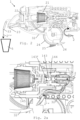
Figure 1 shows in cross-section and partly schematically part of a beverage machine according to the invention in a configuration for preparing a beverage in its mixing unit and dispensing the prepared beverage therefrom; -
Figure 1a is an enlarged view of the mixing unit ofFig. 1 and the supply of water thereto; -
Figure 2 shows in cross-section part of the beverage machine ofFig. 1 in a configuration for supplying water to a further unit; and -
Figure 2a is an enlarged view of the further unit ofFig. 2 and the supply of water thereto. -
Figures 1 to 2a , in which the same references generally designate the same elements, illustrate an embodiment of abeverage preparation machine 1 according to the invention. -
Machine 1 can be configured for preparing a beverage from an ingredient selected from coffee, tea, cocoa, milk, chocolate and soup. -
Machin 1 has awater circuit water 2,2',2'' from asource 11, e.g. a tank and/or a water distribution network. - For instance,
water circuit liquid driver 12, e.g. a pump, and athermal conditioner 13, e.g. aheater 13 and/or a cooler.Pump 12 can be fluidically connected to aheater 13 for drivingwater 2 from aheater inlet 131 to aheater outlet 133 via aheating duct 132. -
Machine 1 has a mixingunit 20 fluidically connected towater circuit beverage outlet 23 for dispensing to a consumer cup or mug 5 abeverage 3 formed in mixingunit 20. Mixingunit 20 has afirst module 21 and asecond module 22 that are relatively movable from: - a distant configuration for inserting an ingredient between first and
second modules - a proximate position for holding such ingredient between first and
second modules water circuit unit 20 so as to formbeverage 3. -
Machine 1 includes afurther unit 30 fluidically connected towater circuit outlet 33 for dispensing to a consumer cup or mug water 2'' supplied bywater circuit further unit 30, such as via apipe 32 offurther unit 30 leading tooutlet 33.Water 2" may be dispensed as such or in combination with an ingredient mixed withwater 2" infurther unit 30. -
Machine 1 has awater directing device 14 fluidically connected to:water circuit unit 20; andfurther unit 30.Water directing device 14 has one or more valves 141,142;143,144 that can be opened and closed for controlling a flow ofwater water circuit unit 20 or into aninlet 31 offurther unit 30. -
First module 21 andsecond module 22 may be relatively movable, by amotor 26 and/or a handle, via a transmission such as a transmission comprising at least one of atoothed gear - At least one of first and
second modules unit 20 andinlet 31 of thefurther unit 30. -
Water directing device 14 may be configured to direct the flow ofwater - only into inlet 211 of mixing
unit 20 when first andsecond modules inlet 31 offurther unit 30 when the first and second modules are in their distant configuration; or - into the inlet of the mixing unit, and optionally into the inlet of the further unit, when the first and second modules are in their proximate configuration and only into the inlet of the further unit when the first and second modules are in their distant configuration.
-
Water directing device 30 may include aselector 145 that operates valve(s) 141,142;143,144 for opening and/or closing thereof.Selector 145 can be actuated by at least one of first andsecond modules -
Selector 145 may be associated with areturn spring 146 for automatically returningselector 145 into a position to open or close valve(s) 141,142;143,144. - Mixing
unit 20 andfurther unit 30 can have different flow-through resistances. For instance, valve 141,142 of directingdevice 14 opens and closesinlet 31 ofunit 30 with the lower flow-through resistance so that, when valve 141,142 is open,water 2" fromwater circuit inlet 31 ofunit 30 with the lower flow-through resistance. - For instance,
unit 20 with the higher flow-through resistance,e.g. mixing unit 20, has anupstream control valve water circuit Fig. 1a . - Such a threshold value can be set above 0.2 bar, e.g. in the range of 0.3 to 15 bar. For instance, the threshold value is comprised with 0.5 to 3 bar or within 5 to 12 bar. Control valve 143,143',144 may include a
gate 143 and a resilient element 143', e.g. a spring, that urges thegate 143 into a position sealing anupstream passage 144 intounit 20 with the higher flow-through resistance. SeeFig. 2a . - Valve 141,142 of directing
device 14 opens and closesinlet 31 offurther unit 30. Mixingunit 20 can be associated with a mixing unit valve 143,143',144.Water directing device 14 may be configured to maintain, e.g. maintain mechanically, mixing unit valve 143,143',144 closed when valve 141,142 of the directingdevice 14 is opened so thatinlet 31 of thefurther unit 30 is open. - The mixing unit valve and the upstream control valve can be the same valve 143,143',144.
- Directing
device 14 can have abody 14a that is movable from: - a mixing unit position to bring or maintain mixing unit valve 143,143',144 in the closed position and enable valve 141,142 of directing
device 14 to be in or move into the open position,optionally body 14a mechanically acting directly on mixing unit valve 143,143',144 to maintain it in the closed position; to - a further unit position to bring or maintain valve 141,142 of directing
device 14 in the closed position and enable mixing unit valve 143,143',144 to be in or move into the open position,optionally body 14a mechanically acting directly on valve 141,142 of directingdevice 14 to maintain it in the closed position, -
Body 14a of directingdevice 14 can have a part that maintains mixing unit valve 143,143',144 and that maintains valve 141,142 of directingdevice 14, the part ofbody 14a being an integral part or being made of multiple sub-parts mechanically fixed together. -
Body 14a of directingdevice 14 may be pre-constrained in the mixing unit position and/or in the further unit position, by at least one of amonostable spring element 146 and a bistable spring element. - Selector 145 (when present) can be configured to act on
body 14a of directingdevice 14. For instance,selector 145 is integral with or fixed to or urged againstbody 14a. -
First module 21 andsecond module 22 may in the proximate position a chamber 20' for holding a capsule containing an ingredient to be mixed in the so delimited chamber 20' with water 2' supplied fromwater circuit beverage 3. -
First module 21 can have at least one piercingelement 215 for opening such capsule so as to enable or facilitate a passage ofwater 2" into such capsule. -
Second module 22 may have at least one piercing element or tearing-open element for forming an opening is such capsule so as to enable or facilitate an outflow from such capsule ofbeverage 3 produced by mixing the ingredient with water 2'. -
First module 21 may be hydraulically and/or resiliently movable againstsecond module 22.First module 21 can be movable against second module 22: - in a support element, e.g. in a
hydraulic cage 213, by a hydraulic fluid, such as water 2' supplied bywater circuit first module 21; or - by a spring element, such as a
helicoidal spring 212, mounted on a support element, e.g. a guidingcage 213, againstfirst module 21; or - by both hydraulic fluid 2' in its
corresponding support element 213 and byspring element 212 on itscorresponding support element 213, optionally the support element corresponding to hydraulic fluid 2' and the support element corresponding tospring element 212 forming asingle element 213. -
Water directing device 14 andfirst module 21 orsecond module 22 can be mechanically assembled together directly or indirectly via acommon support element 213, such as theabovementioned support element 213. - First or
second module beverage 3 along a guide 22' tobeverage outlet 23 via an outlet chamber 23'. For instance, outlet chamber 23' has a partition wall 23'' delimiting aprincipal beverage passage 23‴ and an overflow beverage passage 23ʺʺ. A low flow ofbeverage 3 may be guided intobeverage outlet 23 only viaprincipal beverage passage 23‴. A high flow ofbeverage 33 can be guided intobeverage outlet 23 both via the principal and theoverflow beverage passages 23‴ ,23ʺʺ. -
Beverage outlet 23 andfurther unit outlet 33 may be confined within a virtual vertical cylinder having a diameter of less than 3 cm, e.g. less than 2 cm. For instance,outlets
Claims (15)
- A beverage preparation machine (1), such as a machine for preparing a beverage from an ingredient selected from coffee, tea, cocoa, milk, chocolate and soup, such machine having:- a water circuit (12,13) for guiding water (2,2',2" ) from a source (11), such as a water circuit comprising at least one of a liquid driver (12), e.g. a pump, and a thermal conditioner (13), e.g. a heater (13) and/or a cooler, for instance a pump (12) fluidically connected to a heater (13) for driving water (2) from a heater inlet (131) to a heater outlet (133) via a heating duct (132) ;- a mixing unit (20) fluidically connected to the water circuit (12,13) and to a beverage outlet (23) for dispensing to a consumer cup or mug (5) a beverage (3) formed in the mixing unit (20), the mixing unit (20) having a first module (21) and a second module (22) that are relatively movable from:- a distant configuration for inserting an ingredient between the first and second modules (21,22); to- a proximate position for holding such ingredient between the first and second modules (21,22) and combining such ingredient with water (2') supplied by the water circuit (12,13) to the mixing unit (20) so as to form said beverage (3);- a further unit (30) fluidically connected to the water circuit (12,13) and to an outlet (33) for dispensing to a consumer cup or mug water (2ʺ), as such or in combination with an ingredient, supplied by the water circuit (12,13) via the further unit (30), such as via a pipe (32) of the further unit (30) leading to the outlet (33); and- a water directing device (14) fluidically connected to the water circuit (12,13), to the mixing unit (20) and to the further unit (30), the water directing device (14) having one or more valves (141,142;143,144) that can be opened and closed for controlling a flow of water (2,2',2" ) from the water circuit (12,13) selectively into an inlet (211) of the mixing unit (20) or into an inlet (31) of the further unit (30),optionally the first module (21) and the second module (22) being relatively movable, by a motor (26) and/or a handle, via a transmission such as a transmission comprising at least one of a toothed gear (24,25), lever and belt transmission element,at least one of the first and second modules (21,22), by relatively moving between the distant and the proximate configurations, actuating said valve(s) (141,142;143,144) to direct said flow of water selectively into at least one of the inlet (211) of the mixing unit (20) and the inlet (31) of the further unit (30),characterised in that the mixing unit (20) and the further unit (30) have different flow-through resistances, the valve (141,142) of the directing device (14) opening and closing the inlet (31) of the unit (30) with the lower flow-through resistance so that, when said valve (141,142) is open, water (2") from the water circuit (13,14) is predominantly directed, e.g. at least almost exclusively directed, into the inlet (31) of the unit (30) with the lower flow-through resistance.
- The machine of claim 1, wherein the water directing device (14) is configured to direct said flow of water (2,2',2ʺ) :- only into the inlet (211) of the mixing unit (20) when the first and second modules (21,22) are in their proximate configuration and only into the inlet (31) of the further unit (30) when the first and second modules are in their distant configuration; or- into the inlet of the mixing unit, and optionally into the inlet of the further unit, when the first and second modules are in their proximate configuration and only into the inlet of the further unit when the first and second modules are in their distant configuration.
- The machine of claim 1 or 2, wherein the water directing device (30) comprises a selector (145) that operates said valve(s) (141,142;143,144) for opening and/or closing thereof, the selector (145) being actuated by at least one of the first and second modules (21,22) when relatively moving between the distant and the proximate configurations.
- The machine of claim 3, wherein the selector (145) is associated with a return spring (146) for automatically returning the selector (145) into a position to open or close said valve(s) (141, 142; 143, 144) .
- The machine of any preceding claim, wherein the unit (20) with the higher flow-through resistance, e.g. the mixing unit (20), has an upstream control valve (143,143',144), such as a check-valve or an anti-return valve or a backpressure valve, which enables a flow therethrough of water from the water circuit (12,13) when the control valve (143,143',144) is exposed to an upstream-downstream differential valve pressure that exceeds a threshold value, such as a value above 0.2 bar, for instance a value in the range of 0.3 to 15 bar, e.g. 0.5 to 3 bar or 5 to 12 bar.
- The machine of claim 5, wherein the control valve (143,143',144) comprising a gate (143) and a resilient element (143'), e.g. a spring, that urges the gate (143) into a position sealing an upstream passage (144) into the unit (20) with the higher flow-through resistance.
- The machine of any preceding claim, wherein the valve (141,142) of the directing device (14) opens and closes the inlet (31) of the further unit (30), the mixing unit (20) being associated with a mixing unit valve (143,143',144), the water directing device (14) being configured to maintain, e.g. maintain mechanically, the mixing unit valve (143,143',144) closed when the valve (141,142) of the directing device (14) is opened so that the inlet (31) of the further unit (30) is open.
- The machine of claim 7 when depending on claim 6, wherein the mixing unit valve and the upstream control valve are the same valve (143,143',144).
- The machine of claim 7 or 8, wherein the directing device (14) has a body (14a) that is movable from:- a mixing unit position to bring or maintain the mixing unit valve (143,143',144) in the closed position and enable the valve (141,142) of the directing device (14) to be in or move into the open position, optionally the body (14a) mechanically acting directly on the mixing unit valve (143,143',144) to maintain it in the closed position; to- a further unit position to bring or maintain the valve (141,142) of the directing device (14) in the closed position and enable the mixing unit valve (143,143',144) to be in or move into the open position, optionally the body (14a) mechanically acting directly on the valve (141,142) of the directing device (14) to maintain it in the closed position,and/or vice versa,
optionally the body (14a) of the directing device (14):- having a part that maintains the mixing unit valve (143,143',144) and that maintains the valve (141,142) of the directing device (14), the part of the body (14a) being an integral part or being made of multiple sub-parts mechanically fixed together; and/or- being pre-constrained in the mixing unit position and/or in the further unit position, by at least one of a monostable spring element (146) and a bistable spring element. - The machine of claim 9 when depending on claim 3, wherein the selector (145) is configured to act on the body (14a) of the directing device (14), the selector being optionally integral with or fixed to or urged against the body (14a).
- The machine of any preceding claim, wherein the first module (21) and the second module (22) delimit in the proximate position a chamber (20') for holding a capsule containing an ingredient to be mixed in the so delimited chamber (20') with water (2') supplied from the water circuit (12,13) to form said beverage (3), optionally the first module (21) having at least one piercing element (215) for opening such capsule so as to enable or facilitate a passage of said water (2') into such capsule and/or the second module (22) having at least one piercing element or tearing-open element for forming an opening is such capsule so as to enable or facilitate an outflow from such capsule of beverage (3) produced by mixing said ingredient with said water (2').
- The machine of any preceding claim, wherein the first module (21) is hydraulically and/or resiliently movable against the second module (22), for instance the first module (21) being movable against the second module (22) :- in a support element, e.g. in a hydraulic cage (213), by a hydraulic fluid, such as water (2') supplied by the water circuit (12,13) to the first module (21); or- by a spring element, such as a helicoidal spring (212), mounted on a support element, e.g. a guiding cage (213), against the first module (21); or- by both said hydraulic fluid (2') in its corresponding support element (213) and said spring element (212) on its corresponding support element (213), optionally the support element of the hydraulic fluid (2') and the support element of the spring element (212) forming a single element (213).
- The machine of any preceding claim, wherein the water directing device (14) and the first module (21) or the second module (22) are mechanically assembled together directly or indirectly via a common support element (213), such as via said support element (213) in the machine of claim 12.
- The machine of any preceding claim, wherein the first or second module (21,22) is a downstream module configured to supply said beverage (3) along a guide (22') to the beverage outlet (23) via an outlet chamber (23'), optionally the outlet chamber (23') having a partition wall (23'') delimiting a principal beverage passage (23‴) and an overflow beverage passage (23ʺʺ), such that:- a low flow of beverage (3) is guided into the beverage outlet (23) only via the principal beverage passage (23‴); and- a high flow of beverage (33) is guided into the beverage outlet (23) both via the principal and the overflow beverage passages (23‴,23ʺʺ) .
- The machine of any preceding claim, wherein the beverage outlet (23) and the further unit outlet (33) are confined within a virtual vertical cylinder having a diameter of less than 3 cm, e.g. less than 2 cm, for instance the outlets (23,33) being positioned side-by-side spaced apart or right next to each other, or being positioned one within the other.
Applications Claiming Priority (3)
| Application Number | Priority Date | Filing Date | Title |
|---|---|---|---|
| EP17158383 | 2017-02-28 | ||
| EP17158397 | 2017-02-28 | ||
| PCT/EP2018/054637 WO2018158179A1 (en) | 2017-02-28 | 2018-02-26 | Dispenser with parallel dispensing paths |
Publications (2)
| Publication Number | Publication Date |
|---|---|
| EP3589175A1 EP3589175A1 (en) | 2020-01-08 |
| EP3589175B1 true EP3589175B1 (en) | 2023-08-23 |
Family
ID=61526795
Family Applications (1)
| Application Number | Title | Priority Date | Filing Date |
|---|---|---|---|
| EP18708087.4A Active EP3589175B1 (en) | 2017-02-28 | 2018-02-26 | Dispenser with parallel dispensing paths |
Country Status (4)
| Country | Link |
|---|---|
| US (1) | US11432674B2 (en) |
| EP (1) | EP3589175B1 (en) |
| CN (1) | CN110312453A (en) |
| WO (1) | WO2018158179A1 (en) |
Families Citing this family (18)
| Publication number | Priority date | Publication date | Assignee | Title |
|---|---|---|---|---|
| GB2504947B (en) * | 2012-08-13 | 2015-01-14 | Kraft Foods R & D Inc | Beverage preparation machines |
| US10709283B2 (en) * | 2016-10-31 | 2020-07-14 | Blue Bottle Coffee, Inc. | Flow-optimized pour over coffee brewing system |
| CN109381025B (en) * | 2018-11-15 | 2023-11-17 | 深圳市西啡科技有限公司 | Beverage extraction device and beverage preparation equipment |
| JP2022527510A (en) * | 2019-04-05 | 2022-06-02 | ソシエテ・デ・プロデュイ・ネスレ・エス・アー | Beverage preparation device with a thermally optimized architecture |
| EP3986214A1 (en) | 2019-06-20 | 2022-04-27 | Société des Produits Nestlé S.A. | Beverage preparation device with simple multi-thermal conditioning |
| EP4076104A1 (en) | 2019-12-16 | 2022-10-26 | Société des Produits Nestlé S.A. | Beverage machine carriable single-handed |
| CN114786545A (en) | 2019-12-16 | 2022-07-22 | 雀巢产品有限公司 | Non-thermally regulated beverage preparation machine |
| US20230027842A1 (en) | 2019-12-16 | 2023-01-26 | Societe Des Produits Nestle S.A. | Beverage machine with separable beverage processing unit |
| CN114745991A (en) | 2019-12-16 | 2022-07-12 | 雀巢产品有限公司 | Beverage machine with detachable fluid module |
| EP4076102A1 (en) | 2019-12-16 | 2022-10-26 | Société des Produits Nestlé S.A. | Beverage machine with visible beverage management |
| WO2021122493A1 (en) | 2019-12-16 | 2021-06-24 | Société des Produits Nestlé SA | Beverage machine with an off-set actuator |
| CN114727715A (en) | 2019-12-16 | 2022-07-08 | 雀巢产品有限公司 | Fluid line outside a housing of a lateral beverage machine |
| AU2020405955A1 (en) | 2019-12-16 | 2022-05-12 | Société des Produits Nestlé SA | Beverage machine with actuated water supply valve |
| US20230027124A1 (en) | 2019-12-16 | 2023-01-26 | Societe Des Produits Nestle S.A. | Beverage machine with beverage collector |
| EP4076101A1 (en) | 2019-12-16 | 2022-10-26 | Société des Produits Nestlé S.A. | Beverage machine with simple water driving |
| WO2021191107A1 (en) | 2020-03-24 | 2021-09-30 | Société des Produits Nestlé SA | Beverage preparation machine with handy power management |
| US20220183500A1 (en) * | 2020-12-11 | 2022-06-16 | Hamilton Beach Brands, Inc. | Beverage-Making Machine |
| DE102021123553A1 (en) | 2021-09-10 | 2023-03-16 | Eugster / Frismag Ag | Brewing unit with hydraulic infusion means and method of operating such a brewing unit |
Family Cites Families (85)
| Publication number | Priority date | Publication date | Assignee | Title |
|---|---|---|---|---|
| FR2299839A1 (en) | 1975-02-04 | 1976-09-03 | Moulinex Sa | Coffee machine with cold water pump in column - has water reservoir, water heating plate and filter in cantilevered head on column |
| CH630165A5 (en) | 1978-04-10 | 1982-05-28 | Turmix Ag | METHOD AND DEVICE FOR SELECTIVE PRODUCTION OF HOT WATER OR STEAM FOR THE PREPARATION OF HOT DRINKS, ESPECIALLY COFFEE MACHINE WITH A DEVICE OF THE SAME TYPE. |
| JPS58222014A (en) | 1982-06-18 | 1983-12-23 | Taisho Pharmaceut Co Ltd | Prostaglandin e1 oil emulsion |
| GB8304441D0 (en) | 1983-02-17 | 1983-03-23 | Ruskin B E S | Beverage dispensing apparatus |
| US5019690A (en) | 1989-09-15 | 1991-05-28 | Bunn-O-Matic Corporation | Boiling water dispenser having improved water temperature control system |
| GB9024419D0 (en) | 1990-11-09 | 1991-01-02 | Ist Lab Ltd | Heating apparatus |
| TW199884B (en) | 1991-05-08 | 1993-02-11 | Sociere Des Produits Nestle S A | |
| AU1505192A (en) | 1991-05-10 | 1992-11-12 | Societe Des Produits Nestle S.A. | Sealed cartridge for the prepartion of a beverage |
| US5161455A (en) | 1991-05-15 | 1992-11-10 | Bunn-O-Matic Corporation | Combination coffee and tea brewer |
| IT1252633B (en) | 1991-12-05 | 1995-06-19 | Gianmauro Zani | COMPACT COFFEE MACHINE FOR ESPRESSO COFFEE AND HOT WATER FALL COFFEE FOR FILTRATION OTHERWISE KNOWN AS AMERICAN COFFEE. |
| DE4234746A1 (en) | 1992-10-15 | 1994-04-21 | Braun Ag | Pump for household appliances |
| IT1263761B (en) | 1993-01-19 | 1996-08-29 | DEVICE FOR THE PRODUCTION OF FOAMING STEAM, ESPECIALLY FOR EQUIPMENT FOR THE PRODUCTION OF HOT DRINKS | |
| US5353692A (en) | 1993-09-29 | 1994-10-11 | Unidynamics Corporation | Hot beverage brewing apparatus |
| FR2721381B1 (en) | 1994-06-20 | 1996-08-02 | Seb Sa | Device for producing hot water or steam. |
| DE19611450C1 (en) | 1996-03-22 | 1997-07-03 | Braun Ag | Device for heating and foaming milk for preparation of cappuccino drink |
| DE19732414A1 (en) | 1997-07-30 | 1999-02-04 | Suhl Elektro & Hausgeraetewerk | Throughflow heater for heating liquids e.g. water |
| DE19737694C1 (en) | 1997-08-29 | 1998-10-29 | August Balke Elektro Geraete G | Continuous-flow heater for free-flowing foodstuffs |
| DE19921483C1 (en) | 1999-05-08 | 2000-08-17 | Braun Gmbh | Appts for foaming milk has a steam pipe with an end jet extending from a base body with a sliding vertical movement in a housing to move the jet in and out of the milk without holding the vessel |
| FR2799630B1 (en) | 1999-10-14 | 2002-07-05 | Seb Sa | TEMPERATURE REGULATION OF AN EXPRESSO COFFEE MAKER |
| DE29923063U1 (en) | 1999-12-31 | 2000-03-02 | Eugster Frismag Ag | Device for displaying the calcification status of instantaneous water heaters, in particular espresso machines |
| US6459854B1 (en) | 2000-01-24 | 2002-10-01 | Nestec S.A. | Process and module for heating liquid |
| TWI236360B (en) | 2000-06-30 | 2005-07-21 | Nestle Sa | Capsule cage |
| EP1501398B1 (en) | 2002-05-06 | 2006-09-27 | Gruppo Cimbali S.p.A. | Device for heating and working up milk |
| DE60227248D1 (en) | 2002-07-12 | 2008-08-07 | Nestec Sa | Device for heating a liquid |
| US6889598B2 (en) | 2002-08-13 | 2005-05-10 | Food Equipment Technologies Company, Inc. | Beverage apparatus with power switch cooling system and method |
| FR2844441B1 (en) | 2002-09-16 | 2006-03-31 | Cie Mediterraneenne Des Cafes | MACHINE FOR THE PRODUCTION OF DRINK BY HOT WATER INFUSION |
| GB2397503B (en) | 2003-01-24 | 2005-03-02 | Kraft Foods R & D Inc | Machine for the preparation of beverages |
| DE10322034A1 (en) | 2003-05-16 | 2004-12-02 | Stiebel Eltron Gmbh & Co. Kg | A throughflow water heater has concentric tubes having a spiral fin around the inner and thick film surface heating elements with the water flowing through the tubes |
| FR2855359B1 (en) | 2003-05-19 | 2005-07-01 | Seb Sa | DEVICE FOR HEATING A LIQUID FOR AN ELECTRICAL APPLIANCE, AN ELECTRICAL APPLIANCE EQUIPPED WITH SUCH A DEVICE. |
| EP1495702A1 (en) | 2003-07-10 | 2005-01-12 | Nestec S.A. | Device for the extraction of a cartridge |
| ES2315665T3 (en) * | 2003-08-05 | 2009-04-01 | Gaillard, Jean-Paul | DEVICE FOR THE PREPARATION OF A COFFEE DRINK. |
| EP1634520A1 (en) | 2004-09-13 | 2006-03-15 | Nestec S.A. | Device and method for heating a liquid |
| ES2360218T3 (en) | 2004-11-11 | 2011-06-01 | Nestec S.A. | MIXING HEAD SELF-CLEANING TO PRODUCE A MILK BASED MIXTURE AND DRINK PRODUCTION MACHINES UNDERSTANDING SUCH MIXING HEAD. |
| ES2330810T3 (en) | 2005-06-07 | 2009-12-15 | Nestec S.A. | FOAM DISTRIBUTOR WITH MILK VESSEL, DISPOSABLE NOZZLE AND DRIP TRAY DEVICE FOR DIFFERENT HEIGHT CONTAINERS. |
| EP1968894A1 (en) | 2005-07-16 | 2008-09-17 | Clariant International Ltd. | Method for producing coloured nanocorundum |
| DE602005021827D1 (en) | 2005-09-20 | 2010-07-22 | Nestec Sa | Thermoblock-based beverage production device with a brewing chamber |
| PT1776905E (en) | 2005-10-21 | 2008-03-31 | Gruppo Cimbali Spa | A method for heating and whipping milk and a device for carrying out the method |
| DE602005019216D1 (en) * | 2005-11-22 | 2010-03-18 | Saeco Ipr Ltd | COFFEE PREPARATION DEVICE |
| EP1859714B2 (en) | 2006-05-24 | 2015-05-27 | Nestec S.A. | Brewing device and brewing capsule system with a capsule holder for facilitating insertion and removal of capsules |
| DE602006019159D1 (en) | 2006-05-24 | 2011-02-03 | Nestec Sa | Brewing device for capsule with locking mechanism with variable transmission ratio |
| ES2456273T3 (en) | 2006-06-16 | 2014-04-21 | Nestec S.A. | Coating compositions |
| DE102006043903B3 (en) | 2006-09-19 | 2008-02-28 | BSH Bosch und Siemens Hausgeräte GmbH | Coffee machine, to dispense coffee in cup portions, has a hot brew outflow with a relative movement against the steam/foamed milk outflow |
| WO2008037642A2 (en) | 2006-09-26 | 2008-04-03 | Nestec S.A. | Extraction system for the preparation of a beverage from a cartridge |
| CL2008002963A1 (en) | 2007-10-04 | 2010-01-22 | Nestec Sa | Heating device for a machine for the preparation of liquid food or drink, comprising a thermal unit with a metallic mass, through which the liquid circulates, and accumulates heat and supplies it to the liquid, and has one or more insured electrical components rigidly to the thermal unit; and machine. |
| AU2008306060C1 (en) | 2007-10-04 | 2015-08-27 | Société des Produits Nestlé S.A. | Beverage brewing unit |
| KR20100065200A (en) | 2007-10-04 | 2010-06-15 | 네스텍 소시에테아노님 | Integrated heater for a beverage preparation device |
| ES2391160T3 (en) | 2007-12-12 | 2012-11-22 | Nestec S.A. | Capsule or beaker receptacle used for liquid food or beverage machines |
| EP2070454B1 (en) | 2007-12-12 | 2015-07-15 | Nestec S.A. | Beverage production machines comprising a plurality of core units |
| US9572450B2 (en) | 2008-03-20 | 2017-02-21 | Nestec S.A. | Beverage production device for producing a beverage from a single-use capsule |
| US8850957B2 (en) | 2008-04-22 | 2014-10-07 | Nestec S.A. | Modular assembly of a beverage preparation machine |
| PT2276380E (en) | 2008-05-07 | 2013-08-23 | Nestec Sa | Used capsule collector for beverage devices |
| PT2119386E (en) | 2008-05-15 | 2011-03-03 | De Longhi Spa | Coffee machine |
| EP2296515B1 (en) | 2008-05-28 | 2012-07-18 | Nestec S.A. | Pump for liquid beverage preparation devices |
| JP5671458B2 (en) | 2008-07-09 | 2015-02-18 | ネステク ソシエテ アノニム | Device for filling liquid foods or beverages into containers |
| RU2506876C2 (en) | 2008-07-14 | 2014-02-20 | Нестек С.А. | Water circulation system in beverage preparation device |
| PT2410894E (en) | 2009-03-23 | 2014-05-02 | Nestec Sa | Pump mount in a beverage preparation machine |
| CA2776298C (en) | 2009-10-05 | 2017-08-22 | Nestec S.A. | Cartridge extraction device |
| AU2010326758B2 (en) * | 2009-12-01 | 2014-09-18 | Nestec S.A. | Cartridge extraction device |
| EP2353469A1 (en) * | 2010-02-03 | 2011-08-10 | Nestec S.A. | Beverage preparation machine for large size beverages |
| EP2547240B1 (en) | 2010-03-19 | 2018-12-26 | Nestec S.A. | A beverage machine using ingredient capsules |
| PT2571407E (en) | 2010-05-21 | 2014-05-02 | Nestec Sa | Storable hot water or steam delivery device |
| WO2011147796A1 (en) | 2010-05-25 | 2011-12-01 | Compagnie Mediterraneenne Des Cafes | System for making beverages by infusion |
| ES2561669T3 (en) | 2010-06-09 | 2016-02-29 | Nestec S.A. | Ergonomic service installation for a beverage machine |
| AU2011267130B2 (en) | 2010-06-17 | 2015-11-19 | Société des Produits Nestlé S.A. | Fast heat-up of a thermal conditioning device e.g. for coffee machine |
| ES2674876T3 (en) | 2010-07-12 | 2018-07-04 | Nestec S.A. | Cup holder secured for beverage machine |
| KR20130095757A (en) | 2010-08-27 | 2013-08-28 | 네스텍 소시에테아노님 | Controlled motorized brewing unit |
| RU2013129932A (en) | 2010-12-01 | 2015-01-10 | Нестек С.А. | DRINKING MACHINE WITH A DRINKER |
| CA2843541A1 (en) | 2011-08-25 | 2013-02-28 | Nestec S.A. | Long-lasting cartridge piercer |
| CN103763998B (en) | 2011-08-25 | 2017-08-04 | 雀巢产品技术援助有限公司 | The cartridge chamber of extraction system |
| CN202234830U (en) | 2011-09-06 | 2012-05-30 | 广东新宝电器股份有限公司 | Waterway conversion valve for coffee machine |
| EP2755537B1 (en) | 2011-09-16 | 2017-03-15 | Nestec S.A. | Clean multi-system beverage machine |
| CN202269899U (en) * | 2011-10-13 | 2012-06-13 | 广东德豪润达电气股份有限公司 | Coffee encapsulating machine |
| RU2014138922A (en) | 2012-02-28 | 2016-04-20 | Нестек С.А. | CAPSULE AUTOMATIC BREWER |
| JP2015526122A (en) | 2012-06-15 | 2015-09-10 | ネステク ソシエテ アノニム | Beverage machine with vibration suppression device |
| BR112015010497A2 (en) | 2012-11-13 | 2017-07-11 | Nestec Sa | opener for making large capsule openings |
| CN105263375A (en) * | 2013-04-03 | 2016-01-20 | 2266170安大略公司 | Capsule machine and components |
| WO2015022345A1 (en) | 2013-08-13 | 2015-02-19 | Nestec S.A. | Capsule multi-piercer |
| US9913556B2 (en) | 2014-04-08 | 2018-03-13 | Nestec S.A. | Multisize capsule handling with parallel actuation |
| WO2016096706A1 (en) | 2014-12-18 | 2016-06-23 | Nestec S.A. | Removable cup support platform on collector receptacle |
| RU2711262C2 (en) | 2014-12-18 | 2020-01-16 | Сосьете Де Продюи Нестле С.А. | Beverage preparation machine with cup support coupled with sliding |
| WO2016096707A1 (en) | 2014-12-18 | 2016-06-23 | Nestec S.A. | Beverage machine with self-positioning cup-support |
| WO2016096730A1 (en) * | 2014-12-19 | 2016-06-23 | Koninklijke Philips N.V. | Processing unit, system comprising a consumable and use of a consumable |
| WO2016156364A1 (en) | 2015-04-02 | 2016-10-06 | Nestec S.A. | Shallow machine |
| WO2017001644A1 (en) | 2015-07-02 | 2017-01-05 | Nestec S.A. | Compact integration of capsule handling device |
| WO2018005503A1 (en) * | 2016-06-27 | 2018-01-04 | Sharkninja Operating Llc | Automatic coffee maker and method of preparing a brewed beverage |
-
2018
- 2018-02-26 US US16/488,331 patent/US11432674B2/en active Active
- 2018-02-26 EP EP18708087.4A patent/EP3589175B1/en active Active
- 2018-02-26 WO PCT/EP2018/054637 patent/WO2018158179A1/en unknown
- 2018-02-26 CN CN201880012770.4A patent/CN110312453A/en active Pending
Also Published As
| Publication number | Publication date |
|---|---|
| CN110312453A (en) | 2019-10-08 |
| US11432674B2 (en) | 2022-09-06 |
| WO2018158179A1 (en) | 2018-09-07 |
| EP3589175A1 (en) | 2020-01-08 |
| US20190387918A1 (en) | 2019-12-26 |
Similar Documents
| Publication | Publication Date | Title |
|---|---|---|
| EP3589175B1 (en) | Dispenser with parallel dispensing paths | |
| JP6087955B2 (en) | Multi-system beverage machine | |
| EP2819559B1 (en) | Beverage preparation machine with drop management | |
| EP2645914B1 (en) | Beverage preparation machine with drop collector | |
| EP3525636B1 (en) | Liquid dispensing machine with drop stop | |
| US9913556B2 (en) | Multisize capsule handling with parallel actuation | |
| EP3525634B1 (en) | Liquid dispensing machine with speed regulator | |
| CN103338685A (en) | Beverage machine with reliable user-indicator | |
| US11744397B2 (en) | Beverage machines with modularity | |
| EP3855986B1 (en) | Beverage machine with an actuation distribution | |
| EP3687347B1 (en) | Beverage machines with a removable module | |
| AU2001262188B2 (en) | Device for the extraction of a substance having a moveable component | |
| AU2018387159A1 (en) | Beverage preparation machine with drop evacuation |
Legal Events
| Date | Code | Title | Description |
|---|---|---|---|
| STAA | Information on the status of an ep patent application or granted ep patent |
Free format text: STATUS: UNKNOWN |
|
| STAA | Information on the status of an ep patent application or granted ep patent |
Free format text: STATUS: THE INTERNATIONAL PUBLICATION HAS BEEN MADE |
|
| PUAI | Public reference made under article 153(3) epc to a published international application that has entered the european phase |
Free format text: ORIGINAL CODE: 0009012 |
|
| STAA | Information on the status of an ep patent application or granted ep patent |
Free format text: STATUS: REQUEST FOR EXAMINATION WAS MADE |
|
| 17P | Request for examination filed |
Effective date: 20190930 |
|
| AK | Designated contracting states |
Kind code of ref document: A1 Designated state(s): AL AT BE BG CH CY CZ DE DK EE ES FI FR GB GR HR HU IE IS IT LI LT LU LV MC MK MT NL NO PL PT RO RS SE SI SK SM TR |
|
| AX | Request for extension of the european patent |
Extension state: BA ME |
|
| DAV | Request for validation of the european patent (deleted) | ||
| DAX | Request for extension of the european patent (deleted) | ||
| STAA | Information on the status of an ep patent application or granted ep patent |
Free format text: STATUS: EXAMINATION IS IN PROGRESS |
|
| STAA | Information on the status of an ep patent application or granted ep patent |
Free format text: STATUS: EXAMINATION IS IN PROGRESS |
|
| 17Q | First examination report despatched |
Effective date: 20201113 |
|
| STAA | Information on the status of an ep patent application or granted ep patent |
Free format text: STATUS: EXAMINATION IS IN PROGRESS |
|
| GRAP | Despatch of communication of intention to grant a patent |
Free format text: ORIGINAL CODE: EPIDOSNIGR1 |
|
| STAA | Information on the status of an ep patent application or granted ep patent |
Free format text: STATUS: GRANT OF PATENT IS INTENDED |
|
| INTG | Intention to grant announced |
Effective date: 20230314 |
|
| P01 | Opt-out of the competence of the unified patent court (upc) registered |
Effective date: 20230527 |
|
| GRAS | Grant fee paid |
Free format text: ORIGINAL CODE: EPIDOSNIGR3 |
|
| GRAA | (expected) grant |
Free format text: ORIGINAL CODE: 0009210 |
|
| STAA | Information on the status of an ep patent application or granted ep patent |
Free format text: STATUS: THE PATENT HAS BEEN GRANTED |
|
| AK | Designated contracting states |
Kind code of ref document: B1 Designated state(s): AL AT BE BG CH CY CZ DE DK EE ES FI FR GB GR HR HU IE IS IT LI LT LU LV MC MK MT NL NO PL PT RO RS SE SI SK SM TR |
|
| REG | Reference to a national code |
Ref country code: GB Ref legal event code: FG4D |
|
| REG | Reference to a national code |
Ref country code: CH Ref legal event code: EP |
|
| REG | Reference to a national code |
Ref country code: IE Ref legal event code: FG4D |
|
| REG | Reference to a national code |
Ref country code: DE Ref legal event code: R096 Ref document number: 602018055875 Country of ref document: DE |
|
| REG | Reference to a national code |
Ref country code: NL Ref legal event code: FP |
|
| REG | Reference to a national code |
Ref country code: LT Ref legal event code: MG9D |
|
| REG | Reference to a national code |
Ref country code: AT Ref legal event code: MK05 Ref document number: 1601559 Country of ref document: AT Kind code of ref document: T Effective date: 20230823 |
|
| PG25 | Lapsed in a contracting state [announced via postgrant information from national office to epo] |
Ref country code: GR Free format text: LAPSE BECAUSE OF FAILURE TO SUBMIT A TRANSLATION OF THE DESCRIPTION OR TO PAY THE FEE WITHIN THE PRESCRIBED TIME-LIMIT Effective date: 20231124 |
|
| PG25 | Lapsed in a contracting state [announced via postgrant information from national office to epo] |
Ref country code: IS Free format text: LAPSE BECAUSE OF FAILURE TO SUBMIT A TRANSLATION OF THE DESCRIPTION OR TO PAY THE FEE WITHIN THE PRESCRIBED TIME-LIMIT Effective date: 20231223 |
|
| PG25 | Lapsed in a contracting state [announced via postgrant information from national office to epo] |
Ref country code: SE Free format text: LAPSE BECAUSE OF FAILURE TO SUBMIT A TRANSLATION OF THE DESCRIPTION OR TO PAY THE FEE WITHIN THE PRESCRIBED TIME-LIMIT Effective date: 20230823 Ref country code: RS Free format text: LAPSE BECAUSE OF FAILURE TO SUBMIT A TRANSLATION OF THE DESCRIPTION OR TO PAY THE FEE WITHIN THE PRESCRIBED TIME-LIMIT Effective date: 20230823 Ref country code: PT Free format text: LAPSE BECAUSE OF FAILURE TO SUBMIT A TRANSLATION OF THE DESCRIPTION OR TO PAY THE FEE WITHIN THE PRESCRIBED TIME-LIMIT Effective date: 20231226 Ref country code: NO Free format text: LAPSE BECAUSE OF FAILURE TO SUBMIT A TRANSLATION OF THE DESCRIPTION OR TO PAY THE FEE WITHIN THE PRESCRIBED TIME-LIMIT Effective date: 20231123 Ref country code: LV Free format text: LAPSE BECAUSE OF FAILURE TO SUBMIT A TRANSLATION OF THE DESCRIPTION OR TO PAY THE FEE WITHIN THE PRESCRIBED TIME-LIMIT Effective date: 20230823 Ref country code: LT Free format text: LAPSE BECAUSE OF FAILURE TO SUBMIT A TRANSLATION OF THE DESCRIPTION OR TO PAY THE FEE WITHIN THE PRESCRIBED TIME-LIMIT Effective date: 20230823 Ref country code: IS Free format text: LAPSE BECAUSE OF FAILURE TO SUBMIT A TRANSLATION OF THE DESCRIPTION OR TO PAY THE FEE WITHIN THE PRESCRIBED TIME-LIMIT Effective date: 20231223 Ref country code: HR Free format text: LAPSE BECAUSE OF FAILURE TO SUBMIT A TRANSLATION OF THE DESCRIPTION OR TO PAY THE FEE WITHIN THE PRESCRIBED TIME-LIMIT Effective date: 20230823 Ref country code: GR Free format text: LAPSE BECAUSE OF FAILURE TO SUBMIT A TRANSLATION OF THE DESCRIPTION OR TO PAY THE FEE WITHIN THE PRESCRIBED TIME-LIMIT Effective date: 20231124 Ref country code: FI Free format text: LAPSE BECAUSE OF FAILURE TO SUBMIT A TRANSLATION OF THE DESCRIPTION OR TO PAY THE FEE WITHIN THE PRESCRIBED TIME-LIMIT Effective date: 20230823 Ref country code: AT Free format text: LAPSE BECAUSE OF FAILURE TO SUBMIT A TRANSLATION OF THE DESCRIPTION OR TO PAY THE FEE WITHIN THE PRESCRIBED TIME-LIMIT Effective date: 20230823 |
|
| PGFP | Annual fee paid to national office [announced via postgrant information from national office to epo] |
Ref country code: FR Payment date: 20231229 Year of fee payment: 7 |
|
| PG25 | Lapsed in a contracting state [announced via postgrant information from national office to epo] |
Ref country code: PL Free format text: LAPSE BECAUSE OF FAILURE TO SUBMIT A TRANSLATION OF THE DESCRIPTION OR TO PAY THE FEE WITHIN THE PRESCRIBED TIME-LIMIT Effective date: 20230823 |
|
| PGFP | Annual fee paid to national office [announced via postgrant information from national office to epo] |
Ref country code: NL Payment date: 20240108 Year of fee payment: 7 |