EP0485211A1 - Heating apparatus - Google Patents
Heating apparatus Download PDFInfo
- Publication number
- EP0485211A1 EP0485211A1 EP91310300A EP91310300A EP0485211A1 EP 0485211 A1 EP0485211 A1 EP 0485211A1 EP 91310300 A EP91310300 A EP 91310300A EP 91310300 A EP91310300 A EP 91310300A EP 0485211 A1 EP0485211 A1 EP 0485211A1
- Authority
- EP
- European Patent Office
- Prior art keywords
- heating apparatus
- heating element
- operable
- vessel
- heating
- Prior art date
- Legal status (The legal status is an assumption and is not a legal conclusion. Google has not performed a legal analysis and makes no representation as to the accuracy of the status listed.)
- Granted
Links
Images


Classifications
-
- F—MECHANICAL ENGINEERING; LIGHTING; HEATING; WEAPONS; BLASTING
- F24—HEATING; RANGES; VENTILATING
- F24H—FLUID HEATERS, e.g. WATER OR AIR HEATERS, HAVING HEAT-GENERATING MEANS, e.g. HEAT PUMPS, IN GENERAL
- F24H1/00—Water heaters, e.g. boilers, continuous-flow heaters or water-storage heaters
- F24H1/18—Water-storage heaters
- F24H1/185—Water-storage heaters using electric energy supply
-
- D—TEXTILES; PAPER
- D06—TREATMENT OF TEXTILES OR THE LIKE; LAUNDERING; FLEXIBLE MATERIALS NOT OTHERWISE PROVIDED FOR
- D06F—LAUNDERING, DRYING, IRONING, PRESSING OR FOLDING TEXTILE ARTICLES
- D06F39/00—Details of washing machines not specific to a single type of machines covered by groups D06F9/00 - D06F27/00
- D06F39/04—Heating arrangements
-
- F—MECHANICAL ENGINEERING; LIGHTING; HEATING; WEAPONS; BLASTING
- F24—HEATING; RANGES; VENTILATING
- F24H—FLUID HEATERS, e.g. WATER OR AIR HEATERS, HAVING HEAT-GENERATING MEANS, e.g. HEAT PUMPS, IN GENERAL
- F24H1/00—Water heaters, e.g. boilers, continuous-flow heaters or water-storage heaters
- F24H1/10—Continuous-flow heaters, i.e. heaters in which heat is generated only while the water is flowing, e.g. with direct contact of the water with the heating medium
- F24H1/12—Continuous-flow heaters, i.e. heaters in which heat is generated only while the water is flowing, e.g. with direct contact of the water with the heating medium in which the water is kept separate from the heating medium
- F24H1/121—Continuous-flow heaters, i.e. heaters in which heat is generated only while the water is flowing, e.g. with direct contact of the water with the heating medium in which the water is kept separate from the heating medium using electric energy supply
-
- H—ELECTRICITY
- H05—ELECTRIC TECHNIQUES NOT OTHERWISE PROVIDED FOR
- H05B—ELECTRIC HEATING; ELECTRIC LIGHT SOURCES NOT OTHERWISE PROVIDED FOR; CIRCUIT ARRANGEMENTS FOR ELECTRIC LIGHT SOURCES, IN GENERAL
- H05B3/00—Ohmic-resistance heating
- H05B3/20—Heating elements having extended surface area substantially in a two-dimensional [2D] plane, e.g. plate-heater
- H05B3/22—Heating elements having extended surface area substantially in a two-dimensional [2D] plane, e.g. plate-heater non-flexible
- H05B3/26—Heating elements having extended surface area substantially in a two-dimensional [2D] plane, e.g. plate-heater non-flexible heating conductor mounted on insulating base
- H05B3/262—Heating elements having extended surface area substantially in a two-dimensional [2D] plane, e.g. plate-heater non-flexible heating conductor mounted on insulating base the insulating base being an insulated metal plate
-
- D—TEXTILES; PAPER
- D06—TREATMENT OF TEXTILES OR THE LIKE; LAUNDERING; FLEXIBLE MATERIALS NOT OTHERWISE PROVIDED FOR
- D06F—LAUNDERING, DRYING, IRONING, PRESSING OR FOLDING TEXTILE ARTICLES
- D06F2103/00—Parameters monitored or detected for the control of domestic laundry washing machines, washer-dryers or laundry dryers
- D06F2103/52—Parameters monitored or detected for the control of domestic laundry washing machines, washer-dryers or laundry dryers related to electric heating means, e.g. temperature or voltage
-
- D—TEXTILES; PAPER
- D06—TREATMENT OF TEXTILES OR THE LIKE; LAUNDERING; FLEXIBLE MATERIALS NOT OTHERWISE PROVIDED FOR
- D06F—LAUNDERING, DRYING, IRONING, PRESSING OR FOLDING TEXTILE ARTICLES
- D06F2105/00—Systems or parameters controlled or affected by the control systems of washing machines, washer-dryers or laundry dryers
- D06F2105/10—Temperature of washing liquids; Heating means therefor
-
- D—TEXTILES; PAPER
- D06—TREATMENT OF TEXTILES OR THE LIKE; LAUNDERING; FLEXIBLE MATERIALS NOT OTHERWISE PROVIDED FOR
- D06F—LAUNDERING, DRYING, IRONING, PRESSING OR FOLDING TEXTILE ARTICLES
- D06F2105/00—Systems or parameters controlled or affected by the control systems of washing machines, washer-dryers or laundry dryers
- D06F2105/28—Electric heating
-
- D—TEXTILES; PAPER
- D06—TREATMENT OF TEXTILES OR THE LIKE; LAUNDERING; FLEXIBLE MATERIALS NOT OTHERWISE PROVIDED FOR
- D06F—LAUNDERING, DRYING, IRONING, PRESSING OR FOLDING TEXTILE ARTICLES
- D06F34/00—Details of control systems for washing machines, washer-dryers or laundry dryers
- D06F34/14—Arrangements for detecting or measuring specific parameters
- D06F34/22—Condition of the washing liquid, e.g. turbidity
- D06F34/24—Liquid temperature
-
- H—ELECTRICITY
- H05—ELECTRIC TECHNIQUES NOT OTHERWISE PROVIDED FOR
- H05B—ELECTRIC HEATING; ELECTRIC LIGHT SOURCES NOT OTHERWISE PROVIDED FOR; CIRCUIT ARRANGEMENTS FOR ELECTRIC LIGHT SOURCES, IN GENERAL
- H05B2203/00—Aspects relating to Ohmic resistive heating covered by group H05B3/00
- H05B2203/002—Heaters using a particular layout for the resistive material or resistive elements
- H05B2203/003—Heaters using a particular layout for the resistive material or resistive elements using serpentine layout
-
- H—ELECTRICITY
- H05—ELECTRIC TECHNIQUES NOT OTHERWISE PROVIDED FOR
- H05B—ELECTRIC HEATING; ELECTRIC LIGHT SOURCES NOT OTHERWISE PROVIDED FOR; CIRCUIT ARRANGEMENTS FOR ELECTRIC LIGHT SOURCES, IN GENERAL
- H05B2203/00—Aspects relating to Ohmic resistive heating covered by group H05B3/00
- H05B2203/021—Heaters specially adapted for heating liquids
Definitions
- This invention relates to heating apparatus and in particular but not exclusively to heating apparatus comprising an electric heating element for a washing machine, tumble dryer, dishwasher, water heater, Kettle, shower or hot air blower.
- an electrical heating element generally needs to be supported within the chamber or is located externally of the chamber at a location where heat is conducted or radiated to the vessel.
- heating apparatus comprising a vessel defining a chamber for holding or conducting fluid to be heated and at least one electric heating element arranged to heat a respective heated portion of the vessel wherein the heating element comprises a conductive track of a thick film printed circuit formed on a metal substrate and wherein the metal substrate constitutes the heated portion of the vessel.
- heating element is formed integrally with the vessel and it is therefore not necessary to provide a separate structure for supporting the heating element.
- the apparatus comprises temperature sensing means comprising a thermistor formed as a conductive track of measurable resistance on the thick film circuit.
- the apparatus includes a thermal cut-out connected to the temperature sensing means and arranged to cut off the flow of electric current through the heating element when the temperature sensed by the temperature sensing means exceeds a limiting value.
- the vessel may further comprise an air duct and blower means operable to provide a flow of air through the duct and wherein at least the heated portion of the vessel is located within the duct whereby the apparatus is operable to supply heated liquid and/or heated air.
- Such an arrangement is particularly useful in domestic water heaters for showers and the like where the apparatus may also be used to supply hot air to assist drying. It is therefore no longer necessary to provide a separate structure to support a hot air heating element.
- the vessel includes an inlet connectable in use to a source of liquid and an outlet for the delivery of heated liquid from the chamber, temperature sensing means operable to sense the temperature of liquid flowing from the outlet, and control means operable to regulate the heating current flowing through the heating element in response to the sensed temperature so as to maintain the temperature at a required value.
- a heating element in accordance with the present invention has an inherently low thermal capacity it makes it suitable for use in a heating apparatus where temperature of the heated liquid is controlled in a closed feedback loop arrangement.
- a current regulating circuit operable to regulate current flowing through the heating element is formed as a thick film circuit on the metal substrate of the heating element.
- the heating apparatus further comprises a valve connected in series with the inlet and operable to continuously vary the flow of liquid through the chamber, the valve being provided with a valve sensor operable to provide a disabling signal to the control means representative of the valve being set to provide a flow rate of liquid below a threshold level, wherein the control means is operable to turn off the current to the heating element in response to the disabling signal.
- the disabling signal thereby serves as a safety cut-out to prevent overheating of the heating element when the flow of liquid through the chamber is reduced to a very low level.
- the current regulating circuit is formed on the substrate of the heating element it is also desirable to operate the circuit only when there is a significant flow of liquid through the chamber to ensure that the circuit does not overheat.
- the circuit will typically be located upstream of the heating element with respect to the flow of liquid so that it is cooled by incoming liquid to the chamber.
- the heated portion of the vessel comprises a tubular member defining a fluid passageway and having an external surface upon which the thick film circuit is formed.
- the element may comprise one or more conductive tracks extending helically along the external surface and the connecting means may comprise at least one collar having terminal means cooperating with the conductive track or tracks.
- Such an arrangement is particularly useful as a water heater where the tubular member may be connected in series with a water supply pipe to produce hot water.
- the vessel may alternatively constitute a drum for a washing machine, clothes dryer, dishwasher or the like, the heated portion comprising a panel removably connected to the drum such that a face of the panel forms part of the internal surface of the drum and further comprising seal means operable to peripherally seal the panel to the drum.
- Such an arrangement is preferable to existing drums which include a well within which a conventional heating element is mounted so as to project into the well.
- a conventional heating element When used to heat water as in the case of a washing machine, such wells remain filled with water thereby increasing the total mass of water to be heated during each washing cycle. The contents of the well are also leaked when it is necessary to service the apparatus by removing the heating element.
- the apparatus of the present invention however avoids the need for a well so that the apparatus is more efficient by virtue of having a lower mass of water to be heated at each cycle.
- the heating apparatus may alternatively comprise a kettle having a steam sensor connected to a current regulating circuit formed as a thick film circuit on the metal substrate of the heating element, the circuit being operable in a water boiling mode to deliver a maximum level of current to the heating element until boiling point is sensed by the steam sensor and thereafter to operate in a water simmering mode in which a reduced level of current is delivered to the heating apparatus.
- Such an arrangement has the advantage of avoiding excessive cooling of the water after boiling point is reached and ensures that an unattended kettle of water can be rapidly returned to boiling point when use is required.
- the circuit is connected to temperature sensing means formed on the thick film circuit and is operable in the water simmering mode to regulate the current so as to maintain a required temperature.
- the kettle includes switch means operable to manually select water boiling mode or water simmering mode.
- the substrate is stainless steel.
- the heater assembly 1 of Figure 1 comprises a vessel 2 which resembles in external appearance a flattened bottle having parallel generally flat front and rear faces 3 and 4 respectively.
- An inlet pipe 5 and an outlet pipe 6 are integrally formed with first and second end portions 27 and 28 respectively of the vessel 2 for the inlet and outlet of liquid in use.
- the pipes 5 and 6 include threaded connectors 7 suitable for connection to conventional water pipe couplings.
- the end portions 27 and 28 are formed of a high melting point plastics material.
- Front and rear plates 70 and 71 respectively extend between the end portions 27 and 28 and are connected by side panels 72 and 73 such that the end portions, front and rear plates and side panels together define a chamber communicating with the inlet and outlet pipes 5 and 6.
- the plates 70 and 71 are sealed to the side panels 72 and 73 by gaskets 74 and secured by screws 9.
- Each of the plates 70 and 71 constitutes a stainless steel substrate of a thick film circuit comprising a dielectric layer 75 upon which is formed a heating element 10.
- the heating element 10 comprises a conductive track formed of pure nickel having first and second end portions 11 and 12 respectively with which electrical contact is made by means of spring contacts 13 and 14 respectively of electrical terminals 15 and 16 respectively.
- the heating element 10 follows a path which is of square wave appearance in plan view such that the length of the track is about three times the separation between the terminals 15 and 16 and the effect of passing electric current through the track is to provide heat in a pattern distributed over substantially the whole of the plate 70.
- a resistive track 17 formed of a standard thick film resistor material is also formed on the dielectric layer 75.
- the resistive track 17 has first and second end portions 18 and 19 with which electrical contact is made by spring contacts 20 and 21 respectively of terminals 22 and 23 respectively.
- the resistive track 17 is inter-digitated with the heating element 10 and constitutes a thermistor arranged to sense the overall temperature of the plate 70.
- the plate 70 is additionally provided with an earth terminal 24 which is connected to the substrate by a tag 25.
- a further heating element (not shown) corresponding to heating element 10 is mounted on the rear plate 71 of the vessel 2 and is referred to using corresponding reference numerals for corresponding elements.
- each heating element 10 is energised by applying a voltage across terminals 15 and 16. Electric current flowing through the heating elements 10 provides heat which is conducted through the plates 70, 71 to heat the water.
- the temperature of the heating elements 10 is sensed by a suitable control circuit (not shown) which senses the resistance of resistive track 17 and provides a thermal cut-out if the temperature of the plate exceeds a threshold value.
- the plates 70, 71 are earthed by connecting the earth terminals 28 to a suitable earth point.
- the end portions 27 and 28 may alternatively be formed of metallic material. If connected to a water supply comprising metal piping then such a metallic vessel would include thermally and electrically isolating pipe connectors to isolate the vessel from water supply apparatus.
- the heating apparatus 1 may be used as a domestic water heater and may for example be incorporated in a shower unit.
- Apparatus 30 shown in Figures 2 and 3 incorporates the heating apparatus 1 shown in Figure 1 in a combined water heater and hot air blower unit 31.
- the unit 31 comprises a housing 32 which is generally rectangular in shape and has a rear wall 33 secured to a supporting structure 34.
- the housing 32 defines an air duct 35 extending from an inlet 36 to an outlet 37 and an electrically operated air blower 38 and is operable to provide a flow of air through the duct.
- the heater assembly 1 is supported in the duct 35 such that the plates 70 and 71 are parallel to the rear wall 35 and the relative positions of the inlet 36 and outlet 37 are such that the air flow in the duct passes over the heating elements 10 in a downward direction.
- the inlet pipe 5 of the heater assembly 1 is connected to a water supply pipe 39 which projects from the supporting structure 34 and through the rear wall 33 into the air duct 35.
- the outlet pipe 6 is connected to a water outlet pipe 40 extending through the rear wall 33 and into the supporting structure 34.
- the housing 32 has a front wall 41 upon which are mounted control switches 42 and a thermal cut-out circuit 43.
- a user In use to supply hot water a user operates a water flow control valve (not shown) to permit water to flow through the vessel 2 of the heater assembly 1 and control switches 42 are operated to energise the heating elements 10. Water flowing through the vessel 2 will therefore be heated to a temperature dependent upon the flow rate and the amplitude of heating current. If the flow of water is interrupted then overheating of the plates 70 and 71 above a threshold limit may occur in which case the thermal cut-out circuit 43 operates to discontinue the heating current.
- the unit 31 may alternatively be operated as a hot air blower by actuating control switches 42 to energise the air blower 38 and the heating elements 10 whilst the water control valve remains closed. Air drawn in through the inlet 36 flows through the duct 35 and is heated by the heating elements 10 to emerge from the outlet 37 as hot air.
- the unit 31 may if required be used to deliver simultaneously both hot water and hot air by opening the water control valve.
- the unit 31 may be incorporated in a shower unit in which the water outlet pipe 40 is connected to a shower nozzle and the hot air outlet 37 is positioned to assist drying after use of the shower.
- the unit 31 may alternatively be used to supply hot water to a tap or faucet of a wash basin or bath.
- FIG 4 shows an underneath external view in perspective of a drum 51 of a washing machine 52 which includes a heated panel 50.
- the drum 51 constitutes a vessel defining a chamber receiving water in use.
- the heated panel 50 is constructed in similar manner to the panel 70 of the apparatus of Figure 1 and corresponding reference numerals are used where appropriate in describing corresponding elements.
- the heated panel 50 comprises a stainless steel plate 70 which forms the substrate of a thick film printed circuit in which a heating element 10 is printed onto a dielectric layer 75 on one side of the plate.
- the plate 70 is oriented such that the circuit is formed on a face which is external to the drum 51 and the other face of the plate which is of stainless steel forms part of the inner surface of the drum.
- a temperature sensing resistive track 17 is similarly provided and connected via terminals 22 and 23 to a thermal cut-out circuit.
- the drum 51 has a cylindrical wall 53 in which a rectangular aperture is formed and the plate 70 is connected to the wall 53 by screws 9 so as to close the aperture.
- a sealing gasket 74 provides a peripheral seal to the plate 70.
- a tubular heating apparatus 80 is shown in Figure 5 and comprises a stainless steel pipe 81 having first and second end portions 82 and 83 connected to conventional fluid pipe couplings 84 and 85 respectively formed of a high melting point plastics material.
- a thick film printed circuit 86 is formed on a middle portion 87 of the pipe 81 such that the middle portion of the steel pipe serves as a substrate for the thick film circuit.
- First and second heating elements 88 and 89 respectively are printed on the printed circuit 86 in the form of conductive tracks of pure nickel.
- the heating elements 88 and 89 are each of helical shape and of equal pitch and initiate from diametrically opposed locations so as to remain spaced apart throughout the length of the pipe 81.
- a resistive track 90 is also printed on the printed circuit 86 and follows a helical path of equal pitch to that of the heating elements 88 and 89 so as to remain electrically isolated from each of the heating elements.
- each end portion 82 and 83 electrical connection is made with the heating elements 88 and 89 and the resistive track 90 respectively by means of a respective collar 91 as shown in Figure 6.
- Each collar 91 is formed of an insulating material and carries electrical terminals 92, 93 and 94 which make contact with the heating elements and the resistive track respectively.
- the tubular heating apparatus 80 may be used to heat liquid by passing liquid through the pipe 81 and energising one or both of the heating elements 88 and 89 by connection to a source of electrical current.
- the resistive track 90 may be connected to a thermal cut-out circuit arranged to cut off the electric current if the temperature of the pipe 81 exceeds a threshold value.
- FIG. 7 A further alternative apparatus 100 is shown in Figure 7 constituting a hot water supply system 101 for a domestic shower unit.
- the apparatus 100 comprises a heater assembly 102 shown in Figure 8 and which is similar to the heater assembly 1 of Figure 1. Corresponding reference numerals to those of Figure 1 are used where appropriate for corresponding elements.
- the heater assembly 102 however includes a modified front plate 103 in which heating element 10 is connected to a current regulating circuit 104 in the form of a thick film circuit mounted on the dielectric layer 75.
- the current regulating circuit 104 is of the TRIAC type and receives current from a mains supply via conductors 105.
- the circuit 104 is also connected to a control unit 106 to receive a control signal 113 as illustrated in Figure 7.
- the current regulating circuit 104 also includes a thermal cut-out arranged to shut off power to the heating element 10 in the event of overheating being sensed.
- the heater assembly 102 has an outlet pipe 6 to which is mounted a temperature sensor 107 having an output 112 which is connected to the control unit 106 as illustrated in Figure 7.
- the heater assembly 102 has an inlet pipe 5 to which is mounted a manually operated flow control valve 108 with a flow rate setting control 109.
- the flow control valve 108 is capable of continuous adjustment of flow rate between a minimum flow rate and a maximum flow rate in which the valve is fully opened. Actuation of the flow rate setting control 109 to produce a flow less than a predetermined minimum flow rate results in the flow being completely shut-off.
- the minimum flow rate is in this example 10% of the maximum flow rate.
- the flow control valve 108 is also provided with electric contacts (not shown) responsive to the valve setting being such as to provide less than the predetermined minimum flow rate, the contacts being arranged so as to produce a control signal 110 which is input to the control unit 106.
- a temperature setting control 111 is provided on the control unit 106.
- a user In use, where the outlet pipe 6 is connected to a shower nozzle, a user first selectes a required temperature using the temperature setting control 111 and turns on the flow of water using the flow rate setting control 109 until a required flow rate is received.
- a supply of heating current is delivered to the heating element 10 by the current regulating circuit 104 in response to a command signal 113 from the control unit 106 and water passing through the heater assembly 102 is heated.
- the temperature of water passing through the outlet pipe 6 is sensed by the temperature sensor 107 and the control unit 106 responds to the output signal 112 of the temperature sensor by varying the control signal 113 to the current regulating circuit 104 such that the temperature is stabilised at the selected temperature.
- the hot water supply system 101 is thereby provided with a closed feedback control of temperature.
- the flow rate setting control 109 is set to zero flow thereby generating a control signal 110 which is received by the control unit 106 and results in the current regulating circuit 104 being turned off.
- the control unit 106 includes a safety feature to detect any failure of the mains water supply which would reduce to zero or near zero the flow of water.
- the control unit 106 is for this purpose provided with a trip circuit to shut off power to the heater assembly 102 when the control signal 113 to the current regulating circuit 104 drops below a threshold level (say 10% of the maximum signal level).
- a threshold level say 10% of the maximum signal level.
- the flow control valve 108 remains open but the rate of flow decreases so that progressively less current is required to maintain the temperature at its controlled level. The value of control signal 113 therefore progressively decreases until the threshold level is reached.
- the current regulating circuit 104 is mounted on the front plate 103 at a location upstream of the heating element 10 so that the front plate acts as a heat sink which is cooled by the flow of water. It is therefore not necessary for a separate heat sink to be provided for the current regulating circuit 104.
- the heater assembly 102 allows the use of feedback control of water temperature in a shower by virtue of the low thermal capacity of the plate 103 and heating element 10 when compared with prior art water heaters for this use.
- the heater assembly 102 thereby enables the temperature to be controlled in a manner which is substantially independent of fluctuations in the pressure of mains water supply and fluctuations in the supply temperature.
- the heater assembly 102 also, by virtue of its improved thermal conduction and response time, is able to operate at a lower operating temperature than required in heating elements of prior art devices for this purpose. Where for example in a prior art device a heating element is immersed in the water within the chamber there has been a tendency for the heating element to become furred in use so that it rapidly becomes inefficient.
- the heater assembly of the present invention is less susceptible to furring since it operates at a lower temperature.
- the heating apparatus 100 of Figure 7 may alternatively include a flow valve of a type which includes a time delay facility such that the flow is shut off a few seconds after the minimum flow rate is selected. Additional cooling of the heating apparatus is thereby provided to reduce the initial temperature of water when the valve is turned on after only a short delay. Such a time delay facility will not however generally be necessary because of the inherent low thermal capacity of the heater assembly 102.
- the temperature sensor 107 may comprise a thermistor or like device formed on the thick film circuit of the heating element at a location adjacent to the outlet 6.
- FIG. 9 A further alternative heating apparatus 120 is shown in Figures 9 and 10 and will be described using corresponding reference numerals to those of Figures 7 and 8 where appropriate for corresponding elements.
- the apparatus 120 is similar to the apparatus 100 shown in Figures 7 and 8 and is intended for the supply of hot water for a domestic shower unit.
- the apparatus 120 has an inlet pipe 5 which is lowermost so that water rises through a vessel 121 to emerge from outlet pipe 6 which is uppermost.
- the vessel 121 defines a zig-zag pathway 122 through which the water travels and is overlaid by a heater assembly 102 having a heating element 10 which follows generally the pathway 122.
- the heating element 10 is formed in the same way as that of apparatus 100 and comprises a conductive track formed as a thick film circuit on dielectric layer 75 which in turn is formed on a metal substrate forming part of the vessel 121.
- Apparatus 120 includes a temperature sensor 107 comprising a thermistor formed as a resistive track on the dielectric layer 75.
- the temperature sensor 107 extends into proximity with the outlet pipe 6 so as to enable the outlet water temperature to be sensed.
- a thermal fuse 123 is connected in line with the heating element 10 and is mounted on the dielectric layer 75 as part of the thick film circuit.
- the thermal fuse 123 is operable to shut off current through the heating elements 10 when the temperature of the heater assembly 102 exceeds a safety limit.
- Apparatus 120 includes a control unit 106 performing the same function as that described with reference to apparatus 100 but the control unit of apparatus 120 is formed as part of the same thick film circuit constituted by the heating elements 10, temperature sensor 107 and current regulating circuit 104.
- Components of the control unit 106 are surface mounted on the dielectric layer 75 at a location close to the inlet pipe 5 at which location the metal substrate of the heater assembly 102 is kept cool by the flow of cold water entering the vessel 121.
- the heater assembly 102 is overlaid by a front cover 124 shown partially in Figure 10 and a temperature setting control 111 extends through the front cover so as to be accessible for the setting of the required temperature.
- a further alternative heating apparatus comprising a kettle 130 is shown in Figures 11 and 12 and will be described using corresponding reference numerals to those of preceding figures where appropriate for corresponding elements.
- the kettle 130 comprises a vessel 131 defining an outlet spout 132 and having a removable lid 133 and in this respect resembles a conventional electric kettle.
- the kettle 130 is heated by means of a heater assembly 134 comprising a stainless steel plate 135 which forms an integral part of the vessel 131.
- the plate 135 also constitutes the substrate of a thick film circuit 136 in which a dielectric layer 75 is formed on the plate and carries a heating element 10 in the form of a conductive track as shown in Figure 12.
- a current regulating circuit 104 forms part of the thick film circuit 136 and operates to both control and regulate current passing through the heating element 10 and is connected to a side operated switch 137 which is mounted so as to be manually accessible.
- the vessel 131 is supported on a base 138 which encloses the thick film circuit 136 so as to exclude water and to thermally and electrically isolate the heater assembly from contact with a supporting surface.
- a steam sensor 139 is connected to the current regulating circuit 104 and is located on the vessel 131 so as to provide a signal indicating that water within the vessel is boiling.
- the heating element 10 is also used to sense the temperature of the plate by means of suitable circuitry within the circuit 104 arranged to measure the resistance of the heating element.
- the switch 137 is provided with an "off" position, an "on” position corresponding to a water boiling mode and also an intermediate position corresponding to a water simmering mode in which temperature is controlled at 90°C by regulating the current through the heating element 10 in response to the sensed temperature. In this intermediate position of the switch 137, water can be kept simmering in readiness for being rapidly re-heated to boiling point when required.
- the steam sensor 139 is arranged to sense boiling of the water in the kettle in response to which current through the heating element 10 is reduced by the means of the current regulating circuit 104.
- the current regulating circuit 104 includes a triac circuit enabling the current through the heating element 10 to be continuously varied in order to maintain the water temperature at a required level in the intermediate setting of the control switch 137.
- a thermal fuse (not shown) is also included in the heating element 10 and is arranged to cut off current in the event of temperature exceeding 150°C.
- the current regulating circuit 104 may be arranged to automatically switch the status of the switch 137 from the boiling setting to the intermediate setting in response to boiling point being sensed by the steam sensor 139. Such an arrangement avoids the problem of an unattended kettle automatically switching off in response to boiling point having been reached and the water having cooled excessively when it is required for use. By maintaining the temperature close to boiling point in the intermediate setting of the switch the water can be rapidly returned to boiling point when required.
- the switch 137 may alternatively be a key pad having light emitting diode indicators as to the mode in which the circuit 104 is operating.
- Kettle 130 is provided with a conventional mains socket 140 for connection to a domestic electric mains supply.
- the thick film circuit is formed by initially firing a stainless steel substrate in an oven to form a chromium oxide surface layer, the firing process being carried out at a temperature of 850°C to 900°C.
- a first dielectric adhesion layer is then adhered to the oxidised steel substrate, the adhesion layer being selected to have a coefficient of thermal expansion approximately equal to that of the steel.
- One or more further separate coatings are then separately applied such that the final coating has a coefficient of thermal expansion approximately equal to a thick film ink. Any intermediate buffer coatings are arranged to provide a gradient of intermediate coefficients of thermal expansion.
- a thick film circuit layout is then applied by silk-screen printing in which a conductive track constituting the heating element and a resistive track constituting a temperature sensor are printed.
- An encapsulating layer may then finally be applied over the completed circuit.
- the printing process requires printing onto a cylindrical surface and known techniques exist for such printing in which the substrate is rotated about its cylindrical axis during application of printed layers.
- the thick film circuit may be applied only to one face of the steel sheet or pipe as described above with reference to the examples in Figures 1 to 6.
- the steel sheet or pipe may receive a dielectric coating on both faces. This provides the additional advantage of a protected surface being exposed to the fluid to be heated.
- the heating element may alternatively be formed of other conducting materials such as silver, silver palladium or carbon for example.
Landscapes
- Engineering & Computer Science (AREA)
- Physics & Mathematics (AREA)
- Thermal Sciences (AREA)
- Chemical & Material Sciences (AREA)
- Combustion & Propulsion (AREA)
- Mechanical Engineering (AREA)
- General Engineering & Computer Science (AREA)
- Textile Engineering (AREA)
- Instantaneous Water Boilers, Portable Hot-Water Supply Apparatuses, And Control Of Portable Hot-Water Supply Apparatuses (AREA)
- Yarns And Mechanical Finishing Of Yarns Or Ropes (AREA)
- Control Of Resistance Heating (AREA)
- Resistance Heating (AREA)
- Air-Conditioning For Vehicles (AREA)
- Surface Heating Bodies (AREA)
- General Preparation And Processing Of Foods (AREA)
- Control And Other Processes For Unpacking Of Materials (AREA)
- Heat-Pump Type And Storage Water Heaters (AREA)
Abstract
Description
- This invention relates to heating apparatus and in particular but not exclusively to heating apparatus comprising an electric heating element for a washing machine, tumble dryer, dishwasher, water heater, Kettle, shower or hot air blower.
- It is known to provide electric heating elements comprising a conductive coil of wire or strip of metal through which electric current is passed to heat the element.
- Where it is required to provide electrical heating for fluids such as water contained in a chamber defined by a vessel, an electrical heating element generally needs to be supported within the chamber or is located externally of the chamber at a location where heat is conducted or radiated to the vessel.
- According to the present invention there is disclosed heating apparatus comprising a vessel defining a chamber for holding or conducting fluid to be heated and at least one electric heating element arranged to heat a respective heated portion of the vessel wherein the heating element comprises a conductive track of a thick film printed circuit formed on a metal substrate and wherein the metal substrate constitutes the heated portion of the vessel.
- An advantage of this arrangement is that the heating element is formed integrally with the vessel and it is therefore not necessary to provide a separate structure for supporting the heating element.
- Preferably the apparatus comprises temperature sensing means comprising a thermistor formed as a conductive track of measurable resistance on the thick film circuit.
- Preferably the apparatus includes a thermal cut-out connected to the temperature sensing means and arranged to cut off the flow of electric current through the heating element when the temperature sensed by the temperature sensing means exceeds a limiting value.
- The vessel may further comprise an air duct and blower means operable to provide a flow of air through the duct and wherein at least the heated portion of the vessel is located within the duct whereby the apparatus is operable to supply heated liquid and/or heated air.
- Such an arrangement is particularly useful in domestic water heaters for showers and the like where the apparatus may also be used to supply hot air to assist drying. It is therefore no longer necessary to provide a separate structure to support a hot air heating element.
- Preferably the vessel includes an inlet connectable in use to a source of liquid and an outlet for the delivery of heated liquid from the chamber, temperature sensing means operable to sense the temperature of liquid flowing from the outlet, and control means operable to regulate the heating current flowing through the heating element in response to the sensed temperature so as to maintain the temperature at a required value.
- Since a heating element in accordance with the present invention has an inherently low thermal capacity it makes it suitable for use in a heating apparatus where temperature of the heated liquid is controlled in a closed feedback loop arrangement.
- Preferably a current regulating circuit operable to regulate current flowing through the heating element is formed as a thick film circuit on the metal substrate of the heating element.
- It is therefore not necessary to provide the current regulating circuit with a separate heat sink since the metal substrate serves as an integrally formed heat sink.
- Advantageously the heating apparatus further comprises a valve connected in series with the inlet and operable to continuously vary the flow of liquid through the chamber, the valve being provided with a valve sensor operable to provide a disabling signal to the control means representative of the valve being set to provide a flow rate of liquid below a threshold level, wherein the control means is operable to turn off the current to the heating element in response to the disabling signal.
- The disabling signal thereby serves as a safety cut-out to prevent overheating of the heating element when the flow of liquid through the chamber is reduced to a very low level. Where the current regulating circuit is formed on the substrate of the heating element it is also desirable to operate the circuit only when there is a significant flow of liquid through the chamber to ensure that the circuit does not overheat. The circuit will typically be located upstream of the heating element with respect to the flow of liquid so that it is cooled by incoming liquid to the chamber.
- Conveniently in one embodiment of the invention the heated portion of the vessel comprises a tubular member defining a fluid passageway and having an external surface upon which the thick film circuit is formed. The element may comprise one or more conductive tracks extending helically along the external surface and the connecting means may comprise at least one collar having terminal means cooperating with the conductive track or tracks.
- Such an arrangement is particularly useful as a water heater where the tubular member may be connected in series with a water supply pipe to produce hot water.
- The vessel may alternatively constitute a drum for a washing machine, clothes dryer, dishwasher or the like, the heated portion comprising a panel removably connected to the drum such that a face of the panel forms part of the internal surface of the drum and further comprising seal means operable to peripherally seal the panel to the drum.
- Such an arrangement is preferable to existing drums which include a well within which a conventional heating element is mounted so as to project into the well. When used to heat water as in the case of a washing machine, such wells remain filled with water thereby increasing the total mass of water to be heated during each washing cycle. The contents of the well are also leaked when it is necessary to service the apparatus by removing the heating element. The apparatus of the present invention however avoids the need for a well so that the apparatus is more efficient by virtue of having a lower mass of water to be heated at each cycle.
- The heating apparatus may alternatively comprise a kettle having a steam sensor connected to a current regulating circuit formed as a thick film circuit on the metal substrate of the heating element, the circuit being operable in a water boiling mode to deliver a maximum level of current to the heating element until boiling point is sensed by the steam sensor and thereafter to operate in a water simmering mode in which a reduced level of current is delivered to the heating apparatus.
- Such an arrangement has the advantage of avoiding excessive cooling of the water after boiling point is reached and ensures that an unattended kettle of water can be rapidly returned to boiling point when use is required.
- Preferably the circuit is connected to temperature sensing means formed on the thick film circuit and is operable in the water simmering mode to regulate the current so as to maintain a required temperature.
- Conveniently the kettle includes switch means operable to manually select water boiling mode or water simmering mode.
- Preferably the substrate is stainless steel.
- Particular embodiments of the present invention will now be described by way of example only and with reference to the accompanying drawings of which:-
- Figure 1 is a perspective view of heating apparatus comprising a heater assembly for heating liquid;
- Figure 2 is a front elevation of an alternative heating apparatus comprising a combined water heater and hot air blower unit;
- Figure 3 is a side elevation of the unit of Figure 2;
- Figure 4 is a perspective view of an alternative heating apparatus comprising a heated panel for use in a washing machine;
- Figure 5 is a perspective view of a tubular heating apparatus for heating liquid;
- Figure 6 is a perspective view of a collar of the apparatus of Figure 5;
- Figure 7 is a schematic diagram of a further alternative apparatus comprising a water heater for a shower;
- Figure 8 is a front elevation of a heater assembly of the heating apparatus of Figure 7;
- Figure 9 is a sectioned elevation of a further alternative apparatus comprising a water heater for a shower;
- Figure 10 is an elevation of the heater assembly of Figure 9 showing a heating element and control unit;
- Figure 11 is a sectioned elevation of an alternative apparatus comprising a kettle; and
- Figure 12 is an underneath view of the heating element of the kettle of Figure 11.
- The heater assembly 1 of Figure 1 comprises a vessel 2 which resembles in external appearance a flattened bottle having parallel generally flat front and
rear faces 3 and 4 respectively. - An
inlet pipe 5 and anoutlet pipe 6 are integrally formed with first andsecond end portions pipes end portions - Front and
rear plates end portions side panels outlet pipes - The
plates side panels gaskets 74 and secured byscrews 9. - Each of the
plates dielectric layer 75 upon which is formed aheating element 10. - The
heating element 10 comprises a conductive track formed of pure nickel having first andsecond end portions 11 and 12 respectively with which electrical contact is made by means ofspring contacts electrical terminals heating element 10 follows a path which is of square wave appearance in plan view such that the length of the track is about three times the separation between theterminals plate 70. - A
resistive track 17 formed of a standard thick film resistor material is also formed on thedielectric layer 75. Theresistive track 17 has first andsecond end portions spring contacts terminals resistive track 17 is inter-digitated with theheating element 10 and constitutes a thermistor arranged to sense the overall temperature of theplate 70. - The
plate 70 is additionally provided with anearth terminal 24 which is connected to the substrate by atag 25. - A further heating element (not shown) corresponding to
heating element 10 is mounted on therear plate 71 of the vessel 2 and is referred to using corresponding reference numerals for corresponding elements. - In use as a water heater, water is admitted to the
inlet pipe 5 and delivered from theoutlet pipe 6 whilst eachheating element 10 is energised by applying a voltage acrossterminals heating elements 10 provides heat which is conducted through theplates heating elements 10 is sensed by a suitable control circuit (not shown) which senses the resistance ofresistive track 17 and provides a thermal cut-out if the temperature of the plate exceeds a threshold value. - The
plates earth terminals 28 to a suitable earth point. - The
end portions - The heating apparatus 1 may be used as a domestic water heater and may for example be incorporated in a shower unit.
-
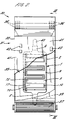
Apparatus 30 shown in Figures 2 and 3 incorporates the heating apparatus 1 shown in Figure 1 in a combined water heater and hot air blower unit 31. - Corresponding reference numerals to those of Figure 1 are used where appropriate for corresponding elements.
- The unit 31 comprises a
housing 32 which is generally rectangular in shape and has arear wall 33 secured to a supportingstructure 34. Thehousing 32 defines anair duct 35 extending from aninlet 36 to anoutlet 37 and an electrically operatedair blower 38 and is operable to provide a flow of air through the duct. - The heater assembly 1 is supported in the
duct 35 such that theplates rear wall 35 and the relative positions of theinlet 36 andoutlet 37 are such that the air flow in the duct passes over theheating elements 10 in a downward direction. - The
inlet pipe 5 of the heater assembly 1 is connected to awater supply pipe 39 which projects from the supportingstructure 34 and through therear wall 33 into theair duct 35. Similarly theoutlet pipe 6 is connected to a water outlet pipe 40 extending through therear wall 33 and into the supportingstructure 34. - The
housing 32 has afront wall 41 upon which are mounted control switches 42 and a thermal cut-out circuit 43. - In use to supply hot water a user operates a water flow control valve (not shown) to permit water to flow through the vessel 2 of the heater assembly 1 and
control switches 42 are operated to energise theheating elements 10. Water flowing through the vessel 2 will therefore be heated to a temperature dependent upon the flow rate and the amplitude of heating current. If the flow of water is interrupted then overheating of theplates out circuit 43 operates to discontinue the heating current. - The unit 31 may alternatively be operated as a hot air blower by actuating control switches 42 to energise the
air blower 38 and theheating elements 10 whilst the water control valve remains closed. Air drawn in through theinlet 36 flows through theduct 35 and is heated by theheating elements 10 to emerge from theoutlet 37 as hot air. The unit 31 may if required be used to deliver simultaneously both hot water and hot air by opening the water control valve. - The unit 31 may be incorporated in a shower unit in which the water outlet pipe 40 is connected to a shower nozzle and the
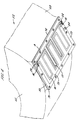
hot air outlet 37 is positioned to assist drying after use of the shower. The unit 31 may alternatively be used to supply hot water to a tap or faucet of a wash basin or bath. - Figure 4 shows an underneath external view in perspective of a
drum 51 of awashing machine 52 which includes aheated panel 50. Thedrum 51 constitutes a vessel defining a chamber receiving water in use. Theheated panel 50 is constructed in similar manner to thepanel 70 of the apparatus of Figure 1 and corresponding reference numerals are used where appropriate in describing corresponding elements. - The
heated panel 50 comprises astainless steel plate 70 which forms the substrate of a thick film printed circuit in which aheating element 10 is printed onto adielectric layer 75 on one side of the plate. Theplate 70 is oriented such that the circuit is formed on a face which is external to thedrum 51 and the other face of the plate which is of stainless steel forms part of the inner surface of the drum. A temperature sensingresistive track 17 is similarly provided and connected viaterminals - The
drum 51 has acylindrical wall 53 in which a rectangular aperture is formed and theplate 70 is connected to thewall 53 byscrews 9 so as to close the aperture. A sealinggasket 74 provides a peripheral seal to theplate 70. - A
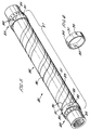
tubular heating aparatus 80 is shown in Figure 5 and comprises astainless steel pipe 81 having first andsecond end portions 82 and 83 connected to conventionalfluid pipe couplings - A thick film printed
circuit 86 is formed on amiddle portion 87 of thepipe 81 such that the middle portion of the steel pipe serves as a substrate for the thick film circuit. - First and
second heating elements circuit 86 in the form of conductive tracks of pure nickel. Theheating elements pipe 81. Aresistive track 90 is also printed on the printedcircuit 86 and follows a helical path of equal pitch to that of theheating elements - At each
end portion 82 and 83 electrical connection is made with theheating elements resistive track 90 respectively by means of arespective collar 91 as shown in Figure 6. Eachcollar 91 is formed of an insulating material and carrieselectrical terminals - The
tubular heating apparatus 80 may be used to heat liquid by passing liquid through thepipe 81 and energising one or both of theheating elements resistive track 90 may be connected to a thermal cut-out circuit arranged to cut off the electric current if the temperature of thepipe 81 exceeds a threshold value. - A further
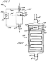
alternative apparatus 100 is shown in Figure 7 constituting a hotwater supply system 101 for a domestic shower unit. - The
apparatus 100 comprises aheater assembly 102 shown in Figure 8 and which is similar to the heater assembly 1 of Figure 1. Corresponding reference numerals to those of Figure 1 are used where appropriate for corresponding elements. Theheater assembly 102 however includes a modifiedfront plate 103 in whichheating element 10 is connected to acurrent regulating circuit 104 in the form of a thick film circuit mounted on thedielectric layer 75. Thecurrent regulating circuit 104 is of the TRIAC type and receives current from a mains supply viaconductors 105. Thecircuit 104 is also connected to acontrol unit 106 to receive acontrol signal 113 as illustrated in Figure 7. - The
current regulating circuit 104 also includes a thermal cut-out arranged to shut off power to theheating element 10 in the event of overheating being sensed. Theheater assembly 102 has anoutlet pipe 6 to which is mounted atemperature sensor 107 having anoutput 112 which is connected to thecontrol unit 106 as illustrated in Figure 7. - The
heater assembly 102 has aninlet pipe 5 to which is mounted a manually operatedflow control valve 108 with a flowrate setting control 109. Theflow control valve 108 is capable of continuous adjustment of flow rate between a minimum flow rate and a maximum flow rate in which the valve is fully opened. Actuation of the flowrate setting control 109 to produce a flow less than a predetermined minimum flow rate results in the flow being completely shut-off. The minimum flow rate is in this example 10% of the maximum flow rate. - The
flow control valve 108 is also provided with electric contacts (not shown) responsive to the valve setting being such as to provide less than the predetermined minimum flow rate, the contacts being arranged so as to produce acontrol signal 110 which is input to thecontrol unit 106. - A
temperature setting control 111 is provided on thecontrol unit 106. - In use, where the
outlet pipe 6 is connected to a shower nozzle, a user first selectes a required temperature using thetemperature setting control 111 and turns on the flow of water using the flowrate setting control 109 until a required flow rate is received. A supply of heating current is delivered to theheating element 10 by thecurrent regulating circuit 104 in response to acommand signal 113 from thecontrol unit 106 and water passing through theheater assembly 102 is heated. The temperature of water passing through theoutlet pipe 6 is sensed by thetemperature sensor 107 and thecontrol unit 106 responds to theoutput signal 112 of the temperature sensor by varying thecontrol signal 113 to thecurrent regulating circuit 104 such that the temperature is stabilised at the selected temperature. - The hot
water supply system 101 is thereby provided with a closed feedback control of temperature. When the user wishes to turn off the flow, the flowrate setting control 109 is set to zero flow thereby generating acontrol signal 110 which is received by thecontrol unit 106 and results in thecurrent regulating circuit 104 being turned off. - The
control unit 106 includes a safety feature to detect any failure of the mains water supply which would reduce to zero or near zero the flow of water. Thecontrol unit 106 is for this purpose provided with a trip circuit to shut off power to theheater assembly 102 when thecontrol signal 113 to thecurrent regulating circuit 104 drops below a threshold level (say 10% of the maximum signal level). In the event of failure of the mains water supply theflow control valve 108 remains open but the rate of flow decreases so that progressively less current is required to maintain the temperature at its controlled level. The value ofcontrol signal 113 therefore progressively decreases until the threshold level is reached. - The
current regulating circuit 104 is mounted on thefront plate 103 at a location upstream of theheating element 10 so that the front plate acts as a heat sink which is cooled by the flow of water. It is therefore not necessary for a separate heat sink to be provided for thecurrent regulating circuit 104. - The
heater assembly 102 allows the use of feedback control of water temperature in a shower by virtue of the low thermal capacity of theplate 103 andheating element 10 when compared with prior art water heaters for this use. - The
heater assembly 102 thereby enables the temperature to be controlled in a manner which is substantially independent of fluctuations in the pressure of mains water supply and fluctuations in the supply temperature. - The
heater assembly 102 also, by virtue of its improved thermal conduction and response time, is able to operate at a lower operating temperature than required in heating elements of prior art devices for this purpose. Where for example in a prior art device a heating element is immersed in the water within the chamber there has been a tendency for the heating element to become furred in use so that it rapidly becomes inefficient. The heater assembly of the present invention is less susceptible to furring since it operates at a lower temperature. - The
heating apparatus 100 of Figure 7 may alternatively include a flow valve of a type which includes a time delay facility such that the flow is shut off a few seconds after the minimum flow rate is selected. Additional cooling of the heating apparatus is thereby provided to reduce the initial temperature of water when the valve is turned on after only a short delay. Such a time delay facility will not however generally be necessary because of the inherent low thermal capacity of theheater assembly 102. Thetemperature sensor 107 may comprise a thermistor or like device formed on the thick film circuit of the heating element at a location adjacent to theoutlet 6. - A further alternative heating apparatus 120 is shown in Figures 9 and 10 and will be described using corresponding reference numerals to those of Figures 7 and 8 where appropriate for corresponding elements.
- The apparatus 120 is similar to the
apparatus 100 shown in Figures 7 and 8 and is intended for the supply of hot water for a domestic shower unit. The apparatus 120 has aninlet pipe 5 which is lowermost so that water rises through avessel 121 to emerge fromoutlet pipe 6 which is uppermost. Thevessel 121 defines a zig-zag pathway 122 through which the water travels and is overlaid by aheater assembly 102 having aheating element 10 which follows generally thepathway 122. - The
heating element 10 is formed in the same way as that ofapparatus 100 and comprises a conductive track formed as a thick film circuit ondielectric layer 75 which in turn is formed on a metal substrate forming part of thevessel 121. - Apparatus 120 includes a
temperature sensor 107 comprising a thermistor formed as a resistive track on thedielectric layer 75. Thetemperature sensor 107 extends into proximity with theoutlet pipe 6 so as to enable the outlet water temperature to be sensed. - A
thermal fuse 123 is connected in line with theheating element 10 and is mounted on thedielectric layer 75 as part of the thick film circuit. Thethermal fuse 123 is operable to shut off current through theheating elements 10 when the temperature of theheater assembly 102 exceeds a safety limit. - Apparatus 120 includes a
control unit 106 performing the same function as that described with reference toapparatus 100 but the control unit of apparatus 120 is formed as part of the same thick film circuit constituted by theheating elements 10,temperature sensor 107 andcurrent regulating circuit 104. Components of thecontrol unit 106 are surface mounted on thedielectric layer 75 at a location close to theinlet pipe 5 at which location the metal substrate of theheater assembly 102 is kept cool by the flow of cold water entering thevessel 121. - The
heater assembly 102 is overlaid by afront cover 124 shown partially in Figure 10 and atemperature setting control 111 extends through the front cover so as to be accessible for the setting of the required temperature. - A further alternative heating apparatus comprising a
kettle 130 is shown in Figures 11 and 12 and will be described using corresponding reference numerals to those of preceding figures where appropriate for corresponding elements. - The
kettle 130 comprises avessel 131 defining anoutlet spout 132 and having aremovable lid 133 and in this respect resembles a conventional electric kettle. Thekettle 130 however is heated by means of aheater assembly 134 comprising astainless steel plate 135 which forms an integral part of thevessel 131. Theplate 135 also constitutes the substrate of athick film circuit 136 in which adielectric layer 75 is formed on the plate and carries aheating element 10 in the form of a conductive track as shown in Figure 12. - A
current regulating circuit 104 forms part of thethick film circuit 136 and operates to both control and regulate current passing through theheating element 10 and is connected to a side operatedswitch 137 which is mounted so as to be manually accessible. - The
vessel 131 is supported on a base 138 which encloses thethick film circuit 136 so as to exclude water and to thermally and electrically isolate the heater assembly from contact with a supporting surface. - A
steam sensor 139 is connected to thecurrent regulating circuit 104 and is located on thevessel 131 so as to provide a signal indicating that water within the vessel is boiling. - The
heating element 10 is also used to sense the temperature of the plate by means of suitable circuitry within thecircuit 104 arranged to measure the resistance of the heating element. Theswitch 137 is provided with an "off" position, an "on" position corresponding to a water boiling mode and also an intermediate position corresponding to a water simmering mode in which temperature is controlled at 90°C by regulating the current through theheating element 10 in response to the sensed temperature. In this intermediate position of theswitch 137, water can be kept simmering in readiness for being rapidly re-heated to boiling point when required. - The
steam sensor 139 is arranged to sense boiling of the water in the kettle in response to which current through theheating element 10 is reduced by the means of thecurrent regulating circuit 104. - Assembly of the
kettle 130 is therefore simpler than in prior art kettles because the circuitry and heating element are integrated onto a single substrate assembly. Thecurrent regulating circuit 104 includes a triac circuit enabling the current through theheating element 10 to be continuously varied in order to maintain the water temperature at a required level in the intermediate setting of thecontrol switch 137. A thermal fuse (not shown) is also included in theheating element 10 and is arranged to cut off current in the event of temperature exceeding 150°C. - The
current regulating circuit 104 may be arranged to automatically switch the status of theswitch 137 from the boiling setting to the intermediate setting in response to boiling point being sensed by thesteam sensor 139. Such an arrangement avoids the problem of an unattended kettle automatically switching off in response to boiling point having been reached and the water having cooled excessively when it is required for use. By maintaining the temperature close to boiling point in the intermediate setting of the switch the water can be rapidly returned to boiling point when required. - The
switch 137 may alternatively be a key pad having light emitting diode indicators as to the mode in which thecircuit 104 is operating. -
Kettle 130 is provided with aconventional mains socket 140 for connection to a domestic electric mains supply. - In each of the above examples the thick film circuit is formed by initially firing a stainless steel substrate in an oven to form a chromium oxide surface layer, the firing process being carried out at a temperature of 850°C to 900°C. A first dielectric adhesion layer is then adhered to the oxidised steel substrate, the adhesion layer being selected to have a coefficient of thermal expansion approximately equal to that of the steel. One or more further separate coatings are then separately applied such that the final coating has a coefficient of thermal expansion approximately equal to a thick film ink. Any intermediate buffer coatings are arranged to provide a gradient of intermediate coefficients of thermal expansion.
- A thick film circuit layout is then applied by silk-screen printing in which a conductive track constituting the heating element and a resistive track constituting a temperature sensor are printed. An encapsulating layer may then finally be applied over the completed circuit. In the case of the
tubular heating apparatus 80 the printing process requires printing onto a cylindrical surface and known techniques exist for such printing in which the substrate is rotated about its cylindrical axis during application of printed layers. - The thick film circuit may be applied only to one face of the steel sheet or pipe as described above with reference to the examples in Figures 1 to 6. Alternatively the steel sheet or pipe may receive a dielectric coating on both faces. This provides the additional advantage of a protected surface being exposed to the fluid to be heated.
- The heating element may alternatively be formed of other conducting materials such as silver, silver palladium or carbon for example.
Claims (16)
- Heating apparatus (1,30,80,100,120,130) comprising a vessel (2) defining a chamber for holding or conducting fluid to be heated and at least one electric heating element (10) arranged to heat a respective heated portion of the vessel characterised in that the heating element comprises a conductive track of a thick film printed circuit formed on a metal substrate (70) and wherein the metal substrate constitutes the heated portion of the vessel.
- Heating apparatus as claimed in claim 1 comprising temperature sensing means comprising a thermistor formed as a conductive track (17) of measurable resistance on the thick film circuit.
- Heating apparatus as claimed in Claim 2 including a thermal cut-out connected to the temperature sensing means and arranged to cut off the flow of electric current through the heating element when the temperature sensed by the temperature sensing means exceeds a limiting value.
- Heating apparatus (100,120,130) as claimed in any preceding claim comprising a current regulating circuit (104) operable to regulate current flowing through the heating element (10) and formed as a thick film circuit on the metal substrate of the heating element.
- Heating apparatus as claimed in any preceding claim wherein the vessel includes an inlet (5) connectable in use to a source of liquid and an outlet (6) for the delivery of heated liquid from the chamber, temperature sensing means (17,107) operable to sense the temperature of liquid flowing from the outlet, and control means (106) operable to regulate the heating current flowing through the heating element in response to the sensed temperature so as to maintain the temperature at a required value.
- Heating apparatus as claimed in any of claims 4 and 5 further comprising a valve (108) connected in series with the inlet and operable to continuously vary the flow of liquid through the chamber, the valve being provided with a valve sensor operable to provide a disabling signal (110) to the control means representative of the valve being set to provide a flow rate of liquid below a threshold level, wherein the control means is operable to turn off the current to the heating element in response to the disabling signal.
- Heating apparatus as claimed in any of Claims 5 and 6 wherein the control means comprises a control circuit formed as a thick film circuit on the metal substrate of the heating element.
- Heating apparatus (30) as claimed in any preceding claim comprising an air duct (35) and blower means (38) operable to provide air through the duct and wherein at least the heated portion (70) of the vessel is located within the duct whereby the apparatus is operable to supply heated liquid and/or heated air.
- Heating apparatus (80) as claimed in any preceding claim wherein the heated portion of the vessel comprises a tubular member (81) defining a fluid passageway and having an external surface upon which the thick film circuit is formed.
- Heating apparatus as claimed in claim 9 wherein the element comprises one or more conductive tracks (88,89) extending helically along the external surface.
- Heating apparatus as claimed in any of claims 9 and 10 comprising at least one collar (91) having terminal means (92,93,94) cooperating with the conductive track or tracks.
- Heating apparatus as claimed in any of claims 1, 2 and 3 wherein the vessel constitutes a drum (51) for a washing machine, clothes dryer, dishwasher or the like, the heated portion comprising a panel (50) removably connected to the drum such that a face of the panel forms part of the internal surface of the drum and further comprising seal means operable to peripherally seal the panel to the drum.
- Heating apparatus as claimed in Claim 4 wherein the vessel constitutes a kettle (130) having a steam sensor (139) connected to the current regulating circuit (104), the circuit being operable in a water boiling mode to deliver a maximum level of current to the heating element (10) until boiling point is sensed by the steam sensor and thereafter to operate in a water simmering mode in which a reduced level of current is delivered to the heating element.
- Heating apparatus as claimed in Claim 13 wherein the circuit is connected to temperature sensing means (10) formed on the thick film circuit and is operable in the water simmering mode to regulate the current so as to maintain a required temperature.
- Heating apparatus as claimed in any of Claims 11 and 12 including switch means (137) operable to select water boiling mode or water simmering mode.
- Heating apparatus as claimed in any preceding claim wherein the substrate is stainless steel.
Applications Claiming Priority (2)
| Application Number | Priority Date | Filing Date | Title |
|---|---|---|---|
| GB909024419A GB9024419D0 (en) | 1990-11-09 | 1990-11-09 | Heating apparatus |
| GB9024419 | 1990-11-09 |
Publications (2)
| Publication Number | Publication Date |
|---|---|
| EP0485211A1 true EP0485211A1 (en) | 1992-05-13 |
| EP0485211B1 EP0485211B1 (en) | 1997-06-18 |
Family
ID=10685149
Family Applications (1)
| Application Number | Title | Priority Date | Filing Date |
|---|---|---|---|
| EP91310300A Revoked EP0485211B1 (en) | 1990-11-09 | 1991-11-07 | Heating apparatus |
Country Status (7)
| Country | Link |
|---|---|
| US (1) | US5557704A (en) |
| EP (1) | EP0485211B1 (en) |
| AT (1) | ATE154690T1 (en) |
| DE (1) | DE69126594T2 (en) |
| DK (1) | DK0485211T3 (en) |
| ES (1) | ES2103302T3 (en) |
| GB (1) | GB9024419D0 (en) |
Cited By (57)
| Publication number | Priority date | Publication date | Assignee | Title |
|---|---|---|---|---|
| EP0585015A1 (en) * | 1992-08-13 | 1994-03-02 | Pifco Limited | Apparatus for heating liquid |
| EP0683965A1 (en) * | 1993-02-15 | 1995-11-29 | Strix Limited | Immersion heaters |
| GB2305341A (en) * | 1993-02-15 | 1997-04-02 | Strix Ltd | Mounting immersion heaters to control devices |
| GB2305233A (en) * | 1995-09-15 | 1997-04-02 | Welwyn Components Ltd | Water heater with thick film printed circuit |
| EP0755170A3 (en) * | 1995-07-17 | 1997-06-04 | Prince Castle Inc | Food warmer foil heater and sensor assembly including plural zone heater assembly |
| GB2315925A (en) * | 1996-06-14 | 1998-02-11 | Strix Ltd | Resilient contact for a resistive heating track |
| GB2317219A (en) * | 1996-09-13 | 1998-03-18 | Imi Waterheating Ltd | Waterheaters |
| GB2324014A (en) * | 1997-04-01 | 1998-10-07 | Caradon Mira Ltd | Printed circuit instantaneous electric water heaters |
| EP0894419A1 (en) | 1996-04-18 | 1999-02-03 | Strix Limited | Electric heaters |
| DE19732414A1 (en) * | 1997-07-30 | 1999-02-04 | Suhl Elektro & Hausgeraetewerk | Throughflow heater for heating liquids e.g. water |
| GB2330402A (en) * | 1997-10-17 | 1999-04-21 | Moulinex Sa | Water heater or steam generator with electrical heating element |
| FR2775066A1 (en) * | 1998-02-18 | 1999-08-20 | Joel Bucaille | Plate for heat exchanger bank, providing cooling for machine tools and reaction vessels |
| GB2336481A (en) * | 1998-04-06 | 1999-10-20 | Otter Controls Ltd | Protection of electric heating element |
| FR2778729A1 (en) * | 1998-05-15 | 1999-11-19 | Moulinex Sa | Heater for a domestic electrical appliance, such as a coffee maker. |
| WO1999067873A1 (en) * | 1998-06-24 | 1999-12-29 | Valeo Equipements Electriques Moteur | Vehicle alternator in particular for motor vehicle comprising a passage for engine cooling fluid circulation |
| EP1064826A2 (en) | 1998-03-17 | 2001-01-03 | Strix Limited | Electric heaters |
| EP1369075A1 (en) * | 2002-06-05 | 2003-12-10 | CANDY S.p.A. | Improved dishwashing machine |
| WO2004042132A3 (en) * | 2002-11-07 | 2004-06-10 | Irca Spa | Conduit with improved electric heating element and clothes drying machine provided with such a conduit |
| GB2401422A (en) * | 2003-01-28 | 2004-11-10 | Der Meulen Gijsbert Eimert Van | A fluid heater |
| FR2855359A1 (en) * | 2003-05-19 | 2004-11-26 | Seb Sa | Liquid e.g. water, heating device for e.g. electric coffee maker, has main body with thermal inertia lower than that of aluminum and storing calorific energy from thermal resistor of complementary heating unit |
| WO2005054756A1 (en) * | 2003-12-04 | 2005-06-16 | BSH Bosch und Siemens Hausgeräte GmbH | Plate-shaped heating apparatus and molded part for a continuous flow heater, and continuous flow heater |
| WO2005064243A1 (en) * | 2003-12-23 | 2005-07-14 | BSH Bosch und Siemens Hausgeräte GmbH | Thick-film fluid heater and continuous heating device |
| EP1665887A4 (en) * | 2003-09-17 | 2007-01-24 | Jae-Sang Park | Warming apparatus with heater produced by pcb |
| WO2009043865A2 (en) | 2007-10-04 | 2009-04-09 | Nestec S.A. | Heating device with an integrated thermoblock for a beverage preparation machine |
| EP2060670A1 (en) * | 2007-11-14 | 2009-05-20 | BSH Bosch und Siemens Hausgeräte GmbH | Component for a device that guides liquid and household device for caring for articles of laundry with such a component |
| WO2009101081A1 (en) * | 2008-02-12 | 2009-08-20 | I.R.C.A. S.P.A. Industria Resistenze Corazzate E Affini | Electric heating element |
| WO2009130099A1 (en) | 2008-04-22 | 2009-10-29 | Nestec S.A. | Modular assembly of a beverage preparation machine |
| WO2009012904A3 (en) * | 2007-07-24 | 2010-02-18 | Bleckmann Gmbh & Co. Kg | Compact spiral-throughflow heating unit which can operate at high pressures |
| GB2466219A (en) * | 2008-12-12 | 2010-06-16 | Otter Controls Ltd | Thick film heating element |
| EP2218374A2 (en) | 2007-10-04 | 2010-08-18 | Nestec S.A. | Integrated heater for a beverage preparation device |
| EP2223641A1 (en) | 2009-02-18 | 2010-09-01 | Nestec S.A. | Heating device with a multi powering configuration |
| EP2226584A2 (en) | 2009-03-05 | 2010-09-08 | E.G.O. Elektro-Gerätebau GmbH | Flow heater and method for producing same |
| WO2011144733A2 (en) | 2010-05-21 | 2011-11-24 | Nestec S.A. | Dynamic double-circuit in-line heater |
| WO2011157675A1 (en) | 2010-06-17 | 2011-12-22 | Nestec S.A. | Fast heat-up of a thermal conditioning device e.g. for coffee machine |
| WO2012007260A1 (en) | 2010-07-16 | 2012-01-19 | Nestec S.A. | Advanced heating device |
| GB2483657A (en) * | 2010-09-15 | 2012-03-21 | Topmaster In Tech Ltd | Low power consumption water heating apparatus |
| WO2012072724A1 (en) | 2010-12-02 | 2012-06-07 | Nestec S.A. | Low-inertia thermal sensor in a beverage machine |
| US8613246B2 (en) | 2003-07-10 | 2013-12-24 | Nestec S.A. | Cap extraction device |
| US8863648B2 (en) | 2009-03-23 | 2014-10-21 | Nestec S.A. | Pump mount in a beverage preparation machine |
| FR3030994A1 (en) * | 2014-12-18 | 2016-06-24 | Valeo Systemes Thermiques | ELECTRICAL DEVICE FOR HEATING AT LEAST ONE FLUID FOR A MOTOR VEHICLE AND A HEATING, VENTILATION AND / OR AIR CONDITIONING SYSTEM COMPRISING THE SAME DEVICE |
| EP3040013A1 (en) * | 2014-12-31 | 2016-07-06 | Indesit Company S.p.A. | Household appliances heating method and related washing machine |
| EP3040472A1 (en) * | 2014-12-31 | 2016-07-06 | Indesit Company S.p.A. | Household appliance heating method and related drying or washing-drying machine |
| WO2016177510A1 (en) * | 2015-05-06 | 2016-11-10 | Arcelik Anonim Sirketi | A household appliance provided with a heating element comprising metallic nanowire material |
| EP2694882B1 (en) | 2011-04-01 | 2016-11-23 | Coway Co., Ltd. | Warm water supply device and warm water supply method |
| DE19858137B4 (en) * | 1998-12-16 | 2016-12-15 | BSH Hausgeräte GmbH | Heating for heating the rinsing liquid in a dishwasher |
| US9648983B2 (en) | 2012-05-15 | 2017-05-16 | Bleckmann Gmbh & Co. Kg | Helical dynamic flow through heater |
| US9664414B2 (en) | 2010-07-12 | 2017-05-30 | Bleckmann Gmbh & Co. Kg | Dynamic flow heater |
| EP2986187B1 (en) | 2013-04-19 | 2017-08-23 | BSH Hausgeräte GmbH | Method for controlling a hot drink preparation device |
| CN107166353A (en) * | 2017-06-08 | 2017-09-15 | 广东美的厨房电器制造有限公司 | Steam generator and steam-heating apparatus |
| CZ307069B6 (en) * | 2016-07-18 | 2017-12-27 | Acsc S.R.O. | A device for heating liquids |
| WO2018000497A1 (en) * | 2016-06-29 | 2018-01-04 | 苏州范王式机电科技有限公司 | Vapour generator and vapour device |
| WO2018158179A1 (en) | 2017-02-28 | 2018-09-07 | Nestec Sa | Dispenser with parallel dispensing paths |
| WO2018162609A1 (en) | 2017-03-10 | 2018-09-13 | Nestec Sa | Beverage preparation machine and method for the control of a thermal conditioning device of such a beverage preparation machine |
| WO2019171310A1 (en) * | 2018-03-09 | 2019-09-12 | Formaster S.A. | A flow heater for heating fluid and/or for generating steam, and a heater assembly and a flow device for heating fluid and/or for generating steam comprising such a heater |
| WO2019175555A1 (en) * | 2018-03-14 | 2019-09-19 | One-Lux Ltd | Emergency lighting apparatus, associated method and computer program instructions |
| WO2019197483A1 (en) * | 2018-04-10 | 2019-10-17 | BSH Hausgeräte GmbH | Domestic appliance with at least one heater for a tubular piece through which a fluid flows |
| GB2595630A (en) * | 2020-03-24 | 2021-12-08 | Ferro Tech Bv | Flow through heaters |
Families Citing this family (91)
| Publication number | Priority date | Publication date | Assignee | Title |
|---|---|---|---|---|
| GB9605831D0 (en) * | 1996-03-20 | 1996-05-22 | Philips Electronics Nv | Water heating vessel |
| US5966501A (en) * | 1996-04-19 | 1999-10-12 | Themion Systems International | Method for controlling the viscosity of a fluid in a defined volume |
| US5981911A (en) * | 1996-04-19 | 1999-11-09 | Thermicon Systems International | Method for heating the surface of a food receptacle |
| ES2130004T3 (en) * | 1996-07-15 | 1999-06-16 | Koninkl Philips Electronics Nv | HEAT ELEMENT. |
| NZ335414A (en) * | 1997-01-30 | 2000-10-27 | Fisher & Paykel | Dishwasher chamber having drain pump impeller with upper disc sealing against casing, and lower blade roots radially spaced from hub to allow air accumulation for priming |
| FR2759925B1 (en) * | 1997-02-21 | 1999-05-14 | Sofragraf Ind | APPLICATOR OF HEAT-MELT ADHESIVE AND ADHESIVE STICK DESIGNED TO SUPPLY SUCH AN APPLICATOR |
| DE19728942A1 (en) * | 1997-07-07 | 1999-01-14 | Brugg Rohrsysteme Gmbh | Heated supply pipe carrying fluid |
| DE19825836B4 (en) * | 1998-06-10 | 2006-10-05 | Stiebel Eltron Gmbh & Co. Kg | Method for applying at least one thick-film heating conductor to a water tank and water tank |
| US6305923B1 (en) * | 1998-06-12 | 2001-10-23 | Husky Injection Molding Systems Ltd. | Molding system using film heaters and/or sensors |
| US6262401B1 (en) * | 1998-12-30 | 2001-07-17 | Aos Holding Company | Gold-plated water heater element and method of making same |
| US6140615A (en) * | 1999-01-14 | 2000-10-31 | Sanki Consys Co., Ltd. | Heater apparatus for an aquarium |
| FR2789868B1 (en) * | 1999-02-18 | 2002-09-27 | Moulinex Sa | ELECTRIC KETTLE WITH HEATED METAL PLATE |
| DE19941038A1 (en) * | 1999-08-28 | 2001-03-01 | Guenther Heiskanaltechnik Gmbh | Electric heater for hot runner systems and method for producing such a heater |
| WO2001067819A1 (en) * | 2000-03-03 | 2001-09-13 | Cooper Richard P | Thin film tubular heater |
| US6943325B2 (en) | 2000-06-30 | 2005-09-13 | Balboa Instruments, Inc. | Water heater |
| US7057140B2 (en) | 2000-06-30 | 2006-06-06 | Balboa Instruments, Inc. | Water heater |
| DE10053415A1 (en) * | 2000-10-27 | 2002-05-29 | Bsh Bosch Siemens Hausgeraete | Electric radiator |
| WO2002096290A1 (en) * | 2001-05-31 | 2002-12-05 | Respironics, Inc. | Heater for optical gas sensor |
| US7301125B2 (en) * | 2001-05-31 | 2007-11-27 | Ric Investments, Llc | Heater for optical gas sensor |
| DE10226940C5 (en) | 2001-06-29 | 2024-05-23 | Vorwerk & Co. Interholding Gmbh | Mixing vessel for an electric motor-driven food processor |
| ATE319874T1 (en) * | 2003-12-02 | 2006-03-15 | Dbk David & Baader Gmbh | COVER FOR A CLOTHES DRYER AND METHOD FOR ASSEMBLY THEREOF |
| DE10356790A1 (en) * | 2003-12-04 | 2005-07-07 | BSH Bosch und Siemens Hausgeräte GmbH | Heating device for fluids, water heaters and process for their preparation |
| JP4051038B2 (en) * | 2004-02-10 | 2008-02-20 | エスペック株式会社 | Pipe heater manufacturing method and pipe heater |
| NL1025564C1 (en) * | 2004-02-25 | 2005-08-26 | Ferro Techniek Holding Bv | Heating device for liquids, has heating elements connected to base structure such that non-linear channel is formed between base structure and heating element, to allow flow of liquid for heating |
| NL1026873C2 (en) * | 2004-02-25 | 2005-08-26 | Ferro Techniek Holding Bv | Device and method for heating liquids, and basic structure. |
| US7206506B2 (en) * | 2004-08-24 | 2007-04-17 | Tankless Systems Worldwide Inc. | Fluid heating system |
| WO2006032163A1 (en) * | 2004-09-20 | 2006-03-30 | Mujia Dai | A heating apparatus of an instantaneous electric water heater |
| ITMI20042531A1 (en) * | 2004-12-28 | 2005-03-28 | Iar Siltal Spa | WASHING MACHINE WITH RETRACTABLE ELECTRIC RESISTANCE |
| US9392646B2 (en) * | 2005-02-17 | 2016-07-12 | 417 And 7/8, Llc | Pallet warmer heating unit |
| US20090101632A1 (en) | 2005-02-17 | 2009-04-23 | David Naylor | Heating unit for direct current applications |
| US8633425B2 (en) * | 2005-02-17 | 2014-01-21 | 417 And 7/8, Llc | Systems, methods, and devices for storing, heating, and dispensing fluid |
| US10920379B2 (en) | 2005-02-17 | 2021-02-16 | Greenheat Ip Holdings Llc | Grounded modular heated cover |
| US20090114634A1 (en) | 2005-02-17 | 2009-05-07 | David Naylor | Heating unit for warming fluid conduits |
| US9945080B2 (en) * | 2005-02-17 | 2018-04-17 | Greenheat Ip Holdings, Llc | Grounded modular heated cover |
| US7706671B2 (en) * | 2005-03-16 | 2010-04-27 | B2M Asset Management, Llc | Multi-function liquid container |
| SE528880C2 (en) * | 2005-07-04 | 2007-03-06 | Tetra Laval Holdings & Finance | Method and apparatus for supplying a gas or gas mixture |
| US7415198B2 (en) * | 2006-01-20 | 2008-08-19 | Cheng Ping Lin | Quartz heater tube |
| DE102007007354B4 (en) | 2006-02-20 | 2013-10-10 | Lg Electronics Inc. | Clothes dryer and method of control |
| KR100830514B1 (en) | 2006-06-12 | 2008-05-21 | 엘지전자 주식회사 | Dryer and its control method |
| US7997006B2 (en) * | 2007-01-12 | 2011-08-16 | Lg Electronics Inc. | Laundry machine and control method thereof |
| WO2008096915A1 (en) * | 2007-02-06 | 2008-08-14 | Lg Electronics Inc. | Heating apparatus, and steam generator and home appliance using the same |
| US7732736B2 (en) * | 2007-03-30 | 2010-06-08 | Illinois Tool Works Inc. | Hot melt adhesive hose assembly with thermal fuse link |
| CN100499944C (en) * | 2007-10-01 | 2009-06-10 | 卫民 | A making technology for thick film electric heater |
| AU2008306060C1 (en) | 2007-10-04 | 2015-08-27 | Société des Produits Nestlé S.A. | Beverage brewing unit |
| JP5608647B2 (en) | 2008-08-08 | 2014-10-15 | ネステク ソシエテ アノニム | Beverage device with carrying handle and configurable appearance and secondary functions |
| US20110008030A1 (en) * | 2009-07-08 | 2011-01-13 | Shimin Luo | Non-metal electric heating system and method, and tankless water heater using the same |
| AU2010206053B2 (en) * | 2009-07-31 | 2014-08-07 | ResMed Pty Ltd | Wire Heated Tube with Temperature Control System, Tube Type Detection, and Active Over Temperature Protection for Humidifier for Respiratory Apparatus |
| US9918609B2 (en) | 2009-12-21 | 2018-03-20 | Whirlpool Corporation | Rotating drum filter for a dishwashing machine |
| US8667974B2 (en) | 2009-12-21 | 2014-03-11 | Whirlpool Corporation | Rotating filter for a dishwashing machine |
| US9119515B2 (en) | 2010-12-03 | 2015-09-01 | Whirlpool Corporation | Dishwasher with unitary wash module |
| US9687135B2 (en) | 2009-12-21 | 2017-06-27 | Whirlpool Corporation | Automatic dishwasher with pump assembly |
| US8627832B2 (en) | 2010-12-13 | 2014-01-14 | Whirlpool Corporation | Rotating filter for a dishwashing machine |
| FR2959553B1 (en) * | 2010-04-29 | 2013-11-29 | Mathieu Thomas Gravil | DEVICE FOR HEATING MODULAR AND INSULATED SANITARY WATER |
| GB2481217B (en) | 2010-06-15 | 2017-06-07 | Otter Controls Ltd | Thick film heaters |
| FR2963868B1 (en) * | 2010-08-11 | 2012-09-28 | Valeo Systemes Thermiques | HEAT EXCHANGER COMPRISING A HEATING ELEMENT SERIGRAPHIE |
| US9668636B2 (en) | 2010-11-16 | 2017-06-06 | Whirlpool Corporation | Method and apparatus for dishwasher with common heating element for multiple treating chambers |
| US9113766B2 (en) | 2010-11-16 | 2015-08-25 | Whirlpool Corporation | Method and apparatus for dishwasher with common heating element for multiple treating chambers |
| US9034112B2 (en) * | 2010-12-03 | 2015-05-19 | Whirlpool Corporation | Dishwasher with shared heater |
| US9107559B2 (en) | 2011-05-16 | 2015-08-18 | Whirlpool Corporation | Dishwasher with filter assembly |
| US8733376B2 (en) | 2011-05-16 | 2014-05-27 | Whirlpool Corporation | Dishwasher with filter assembly |
| US20120318296A1 (en) | 2011-06-20 | 2012-12-20 | Whirlpool Corporation | Ultra micron filter for a dishwasher |
| US9265401B2 (en) | 2011-06-20 | 2016-02-23 | Whirlpool Corporation | Rotating filter for a dishwashing machine |
| US9010344B2 (en) | 2011-06-20 | 2015-04-21 | Whirlpool Corporation | Rotating filter for a dishwashing machine |
| US9861251B2 (en) | 2011-06-20 | 2018-01-09 | Whirlpool Corporation | Filter with artificial boundary for a dishwashing machine |
| US9005369B2 (en) | 2011-06-20 | 2015-04-14 | Whirlpool Corporation | Filter assembly for a dishwasher |
| DE102012200398B4 (en) * | 2012-01-12 | 2024-12-24 | BSH Hausgeräte GmbH | Water-conducting household appliance with at least one heating device |
| US9301667B2 (en) | 2012-02-27 | 2016-04-05 | Whirlpool Corporation | Soil chopping system for a dishwasher |
| US9371841B2 (en) | 2012-03-05 | 2016-06-21 | Electrolux Home Products, Inc. | Safety arrangement for an integrated heater, pump, and motor for an appliance |
| US9237836B2 (en) | 2012-05-30 | 2016-01-19 | Whirlpool Corporation | Rotating filter for a dishwasher |
| US9730570B2 (en) | 2012-05-30 | 2017-08-15 | Whirlpool Corporation | Reduced sound with a rotating filter for a dishwasher |
| US9833120B2 (en) | 2012-06-01 | 2017-12-05 | Whirlpool Corporation | Heating air for drying dishes in a dishwasher using an in-line wash liquid heater |
| US9532700B2 (en) | 2012-06-01 | 2017-01-03 | Whirlpool Corporation | Dishwasher with overflow conduit |
| US9451862B2 (en) | 2012-06-01 | 2016-09-27 | Whirlpool Corporation | Dishwasher with unitary wash module |
| DE102012213385A1 (en) * | 2012-07-30 | 2014-05-22 | E.G.O. Elektro-Gerätebau GmbH | Heating and electrical appliance with heating device |
| US9554688B2 (en) | 2012-10-23 | 2017-01-31 | Whirlpool Corporation | Rotating filter for a dishwasher and methods of cleaning a rotating filter |
| FR2999066B1 (en) * | 2012-12-12 | 2017-09-01 | Cie Mediterraneenne Des Cafes | BOILER FOR DRINKING PREPARATION MACHINE |
| US10132525B2 (en) | 2013-03-15 | 2018-11-20 | Peter Klein | High thermal transfer flow-through heat exchanger |
| US9516971B2 (en) * | 2013-03-15 | 2016-12-13 | Peter Klein | High thermal transfer flow-through heat exchanger |
| DE102013010850B4 (en) * | 2013-06-28 | 2019-03-28 | Webasto SE | Electric heating module, electric heater, vehicle and method of making an electric heating module |
| FR3008030B1 (en) * | 2013-07-02 | 2017-02-17 | Valeo Systemes Thermiques | FLUID HEATING DEVICE FOR MOTOR VEHICLE AND APPARATUS FOR HEATING AND / OR AIR CONDITIONING THEREFOR |
| CN107794712B (en) * | 2016-08-29 | 2021-04-23 | 青岛海尔洗涤电器有限公司 | A washing machine and its control method |
| CN110301826B (en) * | 2018-03-20 | 2025-01-10 | 广州胜维电器制造有限公司 | Heating part |
| CN112334048B (en) * | 2018-05-23 | 2023-04-14 | 布瑞威利私人有限公司 | kettle |
| DE102018006300A1 (en) | 2018-08-10 | 2020-02-13 | Truma Gerätetechnik GmbH & Co. KG | heater |
| DE102019133039A1 (en) * | 2019-09-19 | 2021-03-25 | Dbk David + Baader Gmbh | Fluid heater |
| DE102019214588A1 (en) * | 2019-09-24 | 2021-03-25 | Vitesco Technologies GmbH | Electric heater for a vehicle |
| US11730205B2 (en) | 2020-10-20 | 2023-08-22 | Dr. Dabber Inc. | Quick connect adapter and electronic vaporizer having a ceramic heating element having a quick connect adapter |
| US11064738B2 (en) * | 2020-10-20 | 2021-07-20 | Dr. Dabber Inc. | Ceramic heating element with embedded temperature sensor and electronic vaporizer having a ceramic heating element with embedded temperature sensor |
| CN215930157U (en) * | 2021-09-24 | 2022-03-01 | 上海科勒电子科技有限公司 | Driving part of warm air heater and warm air heater |
| DE102023114454A1 (en) * | 2023-06-01 | 2024-12-05 | Dbk David + Baader Gmbh | stoker |
| DE102023121387A1 (en) * | 2023-08-10 | 2025-02-13 | Eberspächer Catem Gmbh & Co. Kg | Electric heater |
Citations (5)
| Publication number | Priority date | Publication date | Assignee | Title |
|---|---|---|---|---|
| DE1806721A1 (en) * | 1968-11-02 | 1970-05-21 | Siemens Elektrogeraete Gmbh | Electrical heating device with laminated insulation |
| FR2246152A1 (en) * | 1973-07-12 | 1975-04-25 | Stackpole Carbon Co | Fabrication of ceramic resistors - involves flame spraying ferrite powder onto ceramic substrate followed by impregnation |
| AT344289B (en) * | 1976-04-08 | 1978-07-10 | Husqvarna Ab | METHOD OF MANUFACTURING A COOKING PAN |
| NL8300308A (en) * | 1983-01-27 | 1984-08-16 | Atag Bv Apparatenfab | Heating device with thick-film resistance layer - behaves as thermistor and is mounted on support to avoid unnecessarily high temps. |
| EP0380140A2 (en) * | 1986-04-11 | 1990-08-01 | ROLITRON Müszaki-Fejlesztö Kisszövetkezet | Method and device for injection of a liquid into the human or animal body as well as method and heating device for temperature control |
Family Cites Families (36)
| Publication number | Priority date | Publication date | Assignee | Title |
|---|---|---|---|---|
| US1233796A (en) * | 1916-07-17 | 1917-07-17 | Halvor H Lyche | Laundry apparatus. |
| US1365499A (en) * | 1919-10-23 | 1921-01-11 | Gen Electric | Surface-alloyed metal |
| CH128404A (en) * | 1926-04-28 | 1928-11-01 | Hauser Dr Max | Ceramic product and method of making the same. |
| US1870619A (en) * | 1928-07-05 | 1932-08-09 | Technidyne Corp | Roaster |
| US2257668A (en) * | 1934-11-10 | 1941-09-30 | Becker Gottfried | Formation of protective layers on iron and steel articles |
| GB513564A (en) * | 1936-12-29 | 1939-10-16 | Schichau F Gmbh | Improvements relating to wear-resistant material |
| FR847074A (en) * | 1938-06-07 | 1939-10-03 | Method and devices for heating pipelines in which fluids circulate | |
| AT205619B (en) * | 1957-02-05 | 1959-10-10 | Kanthal Ab | Electrical resistance element |
| US3108170A (en) * | 1958-02-17 | 1963-10-22 | Maxwell K Murphy | Heating element |
| US3197335A (en) * | 1962-04-09 | 1965-07-27 | Stanley W Leszynski | Surface-mounted electrical resistance structure and method for producing same |
| US3178913A (en) * | 1963-03-15 | 1965-04-20 | Donald M Olson | Washing machine |
| US3349722A (en) * | 1964-11-27 | 1967-10-31 | Cleveland Technical Ct Inc | Electrical resistance rail heater |
| US3505498A (en) * | 1968-07-23 | 1970-04-07 | Minnesota Mining & Mfg | Cooking utensil with integral dielectric layer and electrical heating element |
| US3784788A (en) * | 1971-05-04 | 1974-01-08 | Belling & Co Ltd | Electric liquid boiling apparatus having an electronic temperature sensor control |
| NL7414546A (en) * | 1973-11-15 | 1975-05-20 | Rhone Poulenc Sa | SMOOTH HEATING TUBE AND PROCESS FOR MANUFACTURING IT. |
| US4266987A (en) * | 1977-04-25 | 1981-05-12 | Kennecott Copper Corporation | Process for providing acid-resistant oxide layers on alloys |
| NZ192597A (en) * | 1979-01-15 | 1982-12-21 | J Taylor | Combined switch-on-dry and steam sensitive protector switch unit for electric water boiling jug |
| US4326552A (en) * | 1979-01-23 | 1982-04-27 | Ingo Bleckmann | Heater for heating flows of fluid and dishwashing machine provided therewith |
| US4244755A (en) * | 1979-09-21 | 1981-01-13 | Corning Glass Works | Process for stabilizing metallic cathode ray tube parts |
| US4289270A (en) * | 1980-02-19 | 1981-09-15 | Jack G. Riley | Portable concentrator |
| WO1983000915A1 (en) * | 1981-09-10 | 1983-03-17 | James, John, Frederick, Colston | Water heating apparatus |
| DE3201641A1 (en) * | 1982-01-20 | 1983-07-28 | Elpag AG Chur, 7001 Chur | Process for producing a tubular radiator |
| DD208028A1 (en) * | 1982-07-09 | 1984-03-21 | Elektro U Metallwaren Zwintsch | CONTAINERS FOR THE CONSUMPTION OF LIQUIDS |
| GB2153190B (en) * | 1984-01-14 | 1987-09-09 | Emi Ltd | Improvements in or relating to heaters for water vessels |
| NL8501327A (en) * | 1985-05-09 | 1986-12-01 | Ferro Electronic Bv | HEATING DEVICE FOR HEATING A BODY. |
| CA1243067A (en) * | 1985-08-30 | 1988-10-11 | K.N. Singh Chhatwal | Thermostatically controlled kettles |
| GB8704467D0 (en) * | 1987-02-25 | 1987-04-01 | Thorn Emi Appliances | Electrically resistive tracks |
| JP2642347B2 (en) * | 1987-03-30 | 1997-08-20 | 株式会社東芝 | Manufacturing method of high hardness member |
| DE8709572U1 (en) * | 1987-07-11 | 1988-11-10 | Robert Krups Stiftung & Co KG, 5650 Solingen | Electrically operated device for preparing hot drinks such as coffee, tea, etc. |
| DE8709573U1 (en) * | 1987-07-11 | 1988-11-10 | Robert Krups Stiftung & Co KG, 5650 Solingen | Electrically operated device for preparing hot drinks, such as coffee or similar. |
| DE8712337U1 (en) * | 1987-09-11 | 1988-06-01 | Robert Krups Stiftung & Co KG, 5650 Solingen | Electrically operated device for preparing hot drinks such as coffee, tea, etc. |
| DE3810736A1 (en) * | 1988-03-30 | 1989-10-19 | Bentz & Sohn Melitta | CONTINUOUS HEATER, ESPECIALLY FOR A COFFEE OR TEA MACHINE |
| GB8908366D0 (en) * | 1989-04-13 | 1989-06-01 | Ist Lab Ltd | Improvements in or relating to automotive electrical systems |
| US5188714A (en) * | 1991-05-03 | 1993-02-23 | The Boc Group, Inc. | Stainless steel surface passivation treatment |
| US5270520A (en) * | 1991-09-23 | 1993-12-14 | Helen Of Troy Corporation | Hair styling appliances and heater control circuits therefor |
| US5354967A (en) * | 1992-11-13 | 1994-10-11 | Helen Of Troy Corporation | Hair styling appliance heater and control |
-
1990
- 1990-11-09 GB GB909024419A patent/GB9024419D0/en active Pending
-
1991
- 1991-11-07 ES ES91310300T patent/ES2103302T3/en not_active Expired - Lifetime
- 1991-11-07 DK DK91310300.8T patent/DK0485211T3/en active
- 1991-11-07 AT AT91310300T patent/ATE154690T1/en not_active IP Right Cessation
- 1991-11-07 DE DE69126594T patent/DE69126594T2/en not_active Expired - Fee Related
- 1991-11-07 EP EP91310300A patent/EP0485211B1/en not_active Revoked
-
1994
- 1994-12-02 US US08/352,851 patent/US5557704A/en not_active Expired - Fee Related
Patent Citations (5)
| Publication number | Priority date | Publication date | Assignee | Title |
|---|---|---|---|---|
| DE1806721A1 (en) * | 1968-11-02 | 1970-05-21 | Siemens Elektrogeraete Gmbh | Electrical heating device with laminated insulation |
| FR2246152A1 (en) * | 1973-07-12 | 1975-04-25 | Stackpole Carbon Co | Fabrication of ceramic resistors - involves flame spraying ferrite powder onto ceramic substrate followed by impregnation |
| AT344289B (en) * | 1976-04-08 | 1978-07-10 | Husqvarna Ab | METHOD OF MANUFACTURING A COOKING PAN |
| NL8300308A (en) * | 1983-01-27 | 1984-08-16 | Atag Bv Apparatenfab | Heating device with thick-film resistance layer - behaves as thermistor and is mounted on support to avoid unnecessarily high temps. |
| EP0380140A2 (en) * | 1986-04-11 | 1990-08-01 | ROLITRON Müszaki-Fejlesztö Kisszövetkezet | Method and device for injection of a liquid into the human or animal body as well as method and heating device for temperature control |
Cited By (84)
| Publication number | Priority date | Publication date | Assignee | Title |
|---|---|---|---|---|
| GB2269980A (en) * | 1992-08-13 | 1994-03-02 | Ist Lab Ltd | Apparatus for heating liquid |
| GB2269980B (en) * | 1992-08-13 | 1996-07-03 | Ist Lab Ltd | Apparatus for heating liquid |
| EP0585015A1 (en) * | 1992-08-13 | 1994-03-02 | Pifco Limited | Apparatus for heating liquid |
| US5946448A (en) * | 1993-02-15 | 1999-08-31 | Strix Limited | Methods of assembling immersion heaters with heating elements in the form of printed circuit tracks |
| EP0683965A1 (en) * | 1993-02-15 | 1995-11-29 | Strix Limited | Immersion heaters |
| GB2305341A (en) * | 1993-02-15 | 1997-04-02 | Strix Ltd | Mounting immersion heaters to control devices |
| GB2305341B (en) * | 1993-02-15 | 1997-09-03 | Strix Ltd | Electric liquid heating apparatus |
| EP0755170A3 (en) * | 1995-07-17 | 1997-06-04 | Prince Castle Inc | Food warmer foil heater and sensor assembly including plural zone heater assembly |
| GB2305233A (en) * | 1995-09-15 | 1997-04-02 | Welwyn Components Ltd | Water heater with thick film printed circuit |
| EP0894419A1 (en) | 1996-04-18 | 1999-02-03 | Strix Limited | Electric heaters |
| GB2315925A (en) * | 1996-06-14 | 1998-02-11 | Strix Ltd | Resilient contact for a resistive heating track |
| GB2315925B (en) * | 1996-06-14 | 2001-02-14 | Strix Ltd | Electric heaters |
| GB2317219A (en) * | 1996-09-13 | 1998-03-18 | Imi Waterheating Ltd | Waterheaters |
| GB2324014A (en) * | 1997-04-01 | 1998-10-07 | Caradon Mira Ltd | Printed circuit instantaneous electric water heaters |
| GB2324014B (en) * | 1997-04-01 | 2001-08-22 | Caradon Mira Ltd | Improvements in or relating to electric water heaters |
| DE19732414A1 (en) * | 1997-07-30 | 1999-02-04 | Suhl Elektro & Hausgeraetewerk | Throughflow heater for heating liquids e.g. water |
| GB2330402A (en) * | 1997-10-17 | 1999-04-21 | Moulinex Sa | Water heater or steam generator with electrical heating element |
| FR2775066A1 (en) * | 1998-02-18 | 1999-08-20 | Joel Bucaille | Plate for heat exchanger bank, providing cooling for machine tools and reaction vessels |
| EP1064826A2 (en) | 1998-03-17 | 2001-01-03 | Strix Limited | Electric heaters |
| GB2336481A (en) * | 1998-04-06 | 1999-10-20 | Otter Controls Ltd | Protection of electric heating element |
| GB2336481B (en) * | 1998-04-06 | 2002-10-16 | Otter Controls Ltd | Improvements relating to control of electric heating elements |
| WO1999059453A1 (en) * | 1998-05-15 | 1999-11-25 | Moulinex S.A. | Boiler for household electrical appliance and household electrical appliance comprising same |
| FR2778729A1 (en) * | 1998-05-15 | 1999-11-19 | Moulinex Sa | Heater for a domestic electrical appliance, such as a coffee maker. |
| WO1999067873A1 (en) * | 1998-06-24 | 1999-12-29 | Valeo Equipements Electriques Moteur | Vehicle alternator in particular for motor vehicle comprising a passage for engine cooling fluid circulation |
| FR2780575A1 (en) * | 1998-06-24 | 1999-12-31 | Valeo Equip Electr Moteur | Motor vehicle alternator with internal passages allowing liquid cooling |
| DE19858137B4 (en) * | 1998-12-16 | 2016-12-15 | BSH Hausgeräte GmbH | Heating for heating the rinsing liquid in a dishwasher |
| EP1369075A1 (en) * | 2002-06-05 | 2003-12-10 | CANDY S.p.A. | Improved dishwashing machine |
| WO2004042132A3 (en) * | 2002-11-07 | 2004-06-10 | Irca Spa | Conduit with improved electric heating element and clothes drying machine provided with such a conduit |
| GB2401422A (en) * | 2003-01-28 | 2004-11-10 | Der Meulen Gijsbert Eimert Van | A fluid heater |
| FR2855359A1 (en) * | 2003-05-19 | 2004-11-26 | Seb Sa | Liquid e.g. water, heating device for e.g. electric coffee maker, has main body with thermal inertia lower than that of aluminum and storing calorific energy from thermal resistor of complementary heating unit |
| WO2004105438A1 (en) * | 2003-05-19 | 2004-12-02 | Seb S.A. | Device for heating a liquid for a domestic appliance, domestic appliance fitted with said device |
| US7286752B2 (en) | 2003-05-19 | 2007-10-23 | Seb S.A. | Device for heating a liquid for domestic appliance, domestic appliance fitted with said device |
| US9392901B2 (en) | 2003-07-10 | 2016-07-19 | Nestec S.A. | Cap extraction device |
| US8613246B2 (en) | 2003-07-10 | 2013-12-24 | Nestec S.A. | Cap extraction device |
| EP1665887A4 (en) * | 2003-09-17 | 2007-01-24 | Jae-Sang Park | Warming apparatus with heater produced by pcb |
| WO2005054756A1 (en) * | 2003-12-04 | 2005-06-16 | BSH Bosch und Siemens Hausgeräte GmbH | Plate-shaped heating apparatus and molded part for a continuous flow heater, and continuous flow heater |
| WO2005064243A1 (en) * | 2003-12-23 | 2005-07-14 | BSH Bosch und Siemens Hausgeräte GmbH | Thick-film fluid heater and continuous heating device |
| WO2009012904A3 (en) * | 2007-07-24 | 2010-02-18 | Bleckmann Gmbh & Co. Kg | Compact spiral-throughflow heating unit which can operate at high pressures |
| EP2218376A2 (en) | 2007-10-04 | 2010-08-18 | Nestec S.A. | Heating device with an integrated thermoblock for a beverage preparation machine |
| EP2225974A2 (en) | 2007-10-04 | 2010-09-08 | Nestec S.A. | Heating device with an integrated thermoblock for a beverage preparation machine |
| EP2218375A2 (en) | 2007-10-04 | 2010-08-18 | Nestec S.A. | Heating device with an integrated thermoblock for a beverage preparation machine |
| EP2218374A2 (en) | 2007-10-04 | 2010-08-18 | Nestec S.A. | Integrated heater for a beverage preparation device |
| US10413116B2 (en) | 2007-10-04 | 2019-09-17 | Societe Des Produits Nestle S.A. | Heating device with an integrated thermoblock for a beverage preparation machine |
| EP2218371A2 (en) | 2007-10-04 | 2010-08-18 | Nestec S.A. | Integrated heater for a beverage preparation device |
| EP2218372A2 (en) | 2007-10-04 | 2010-08-18 | Nestec S.A. | Power connector for a heater for a beverage machine |
| EP2218373A2 (en) | 2007-10-04 | 2010-08-18 | Nestec S.A. | Integrated heater for a beverage preparation device |
| WO2009043865A2 (en) | 2007-10-04 | 2009-04-09 | Nestec S.A. | Heating device with an integrated thermoblock for a beverage preparation machine |
| US10413115B2 (en) | 2007-10-04 | 2019-09-17 | Societe Des Produits Nestle S.A. | Heating device with an integrated thermoblock for a beverage preparation machine |
| EP2060670A1 (en) * | 2007-11-14 | 2009-05-20 | BSH Bosch und Siemens Hausgeräte GmbH | Component for a device that guides liquid and household device for caring for articles of laundry with such a component |
| WO2009101081A1 (en) * | 2008-02-12 | 2009-08-20 | I.R.C.A. S.P.A. Industria Resistenze Corazzate E Affini | Electric heating element |
| WO2009130099A1 (en) | 2008-04-22 | 2009-10-29 | Nestec S.A. | Modular assembly of a beverage preparation machine |
| GB2466219A (en) * | 2008-12-12 | 2010-06-16 | Otter Controls Ltd | Thick film heating element |
| EP2223641A1 (en) | 2009-02-18 | 2010-09-01 | Nestec S.A. | Heating device with a multi powering configuration |
| US8334483B2 (en) | 2009-02-18 | 2012-12-18 | Nestec S.A. | Heating device with a multi powering configuration |
| EP2226584A2 (en) | 2009-03-05 | 2010-09-08 | E.G.O. Elektro-Gerätebau GmbH | Flow heater and method for producing same |
| DE102009013269A1 (en) | 2009-03-05 | 2010-09-09 | E.G.O. Elektro-Gerätebau GmbH | Flow heater and method of making a flow heater |
| US8863648B2 (en) | 2009-03-23 | 2014-10-21 | Nestec S.A. | Pump mount in a beverage preparation machine |
| WO2011144733A2 (en) | 2010-05-21 | 2011-11-24 | Nestec S.A. | Dynamic double-circuit in-line heater |
| US10799062B2 (en) | 2010-06-17 | 2020-10-13 | Societe Des Produits Nestle S.A. | Fast heat-up of a thermal conditioning device |
| WO2011157675A1 (en) | 2010-06-17 | 2011-12-22 | Nestec S.A. | Fast heat-up of a thermal conditioning device e.g. for coffee machine |
| US9664414B2 (en) | 2010-07-12 | 2017-05-30 | Bleckmann Gmbh & Co. Kg | Dynamic flow heater |
| US10368689B2 (en) | 2010-07-16 | 2019-08-06 | Societe Des Produits Nestle S.A. | Advanced heating device |
| WO2012007260A1 (en) | 2010-07-16 | 2012-01-19 | Nestec S.A. | Advanced heating device |
| GB2483657B (en) * | 2010-09-15 | 2013-07-31 | Topmaster In Tech Ltd | A mini size low power consumption water heating apparatus and method of manufacturing the same |
| GB2483657A (en) * | 2010-09-15 | 2012-03-21 | Topmaster In Tech Ltd | Low power consumption water heating apparatus |
| WO2012072724A1 (en) | 2010-12-02 | 2012-06-07 | Nestec S.A. | Low-inertia thermal sensor in a beverage machine |
| EP2694882B1 (en) | 2011-04-01 | 2016-11-23 | Coway Co., Ltd. | Warm water supply device and warm water supply method |
| US9648983B2 (en) | 2012-05-15 | 2017-05-16 | Bleckmann Gmbh & Co. Kg | Helical dynamic flow through heater |
| EP2986187B1 (en) | 2013-04-19 | 2017-08-23 | BSH Hausgeräte GmbH | Method for controlling a hot drink preparation device |
| FR3030994A1 (en) * | 2014-12-18 | 2016-06-24 | Valeo Systemes Thermiques | ELECTRICAL DEVICE FOR HEATING AT LEAST ONE FLUID FOR A MOTOR VEHICLE AND A HEATING, VENTILATION AND / OR AIR CONDITIONING SYSTEM COMPRISING THE SAME DEVICE |
| EP3040472A1 (en) * | 2014-12-31 | 2016-07-06 | Indesit Company S.p.A. | Household appliance heating method and related drying or washing-drying machine |
| EP3040013A1 (en) * | 2014-12-31 | 2016-07-06 | Indesit Company S.p.A. | Household appliances heating method and related washing machine |
| WO2016177510A1 (en) * | 2015-05-06 | 2016-11-10 | Arcelik Anonim Sirketi | A household appliance provided with a heating element comprising metallic nanowire material |
| WO2018000497A1 (en) * | 2016-06-29 | 2018-01-04 | 苏州范王式机电科技有限公司 | Vapour generator and vapour device |
| CZ307069B6 (en) * | 2016-07-18 | 2017-12-27 | Acsc S.R.O. | A device for heating liquids |
| WO2018158179A1 (en) | 2017-02-28 | 2018-09-07 | Nestec Sa | Dispenser with parallel dispensing paths |
| WO2018162609A1 (en) | 2017-03-10 | 2018-09-13 | Nestec Sa | Beverage preparation machine and method for the control of a thermal conditioning device of such a beverage preparation machine |
| CN107166353A (en) * | 2017-06-08 | 2017-09-15 | 广东美的厨房电器制造有限公司 | Steam generator and steam-heating apparatus |
| WO2019171310A1 (en) * | 2018-03-09 | 2019-09-12 | Formaster S.A. | A flow heater for heating fluid and/or for generating steam, and a heater assembly and a flow device for heating fluid and/or for generating steam comprising such a heater |
| WO2019175555A1 (en) * | 2018-03-14 | 2019-09-19 | One-Lux Ltd | Emergency lighting apparatus, associated method and computer program instructions |
| WO2019197483A1 (en) * | 2018-04-10 | 2019-10-17 | BSH Hausgeräte GmbH | Domestic appliance with at least one heater for a tubular piece through which a fluid flows |
| CN111936026A (en) * | 2018-04-10 | 2020-11-13 | Bsh家用电器有限公司 | Household appliance comprising a heater having at least one tube for the passage of a fluid |
| GB2595630A (en) * | 2020-03-24 | 2021-12-08 | Ferro Tech Bv | Flow through heaters |
| GB2595630B (en) * | 2020-03-24 | 2022-06-15 | Ferro Tech Bv | Flow through heaters |
Also Published As
| Publication number | Publication date |
|---|---|
| US5557704A (en) | 1996-09-17 |
| GB9024419D0 (en) | 1991-01-02 |
| ES2103302T3 (en) | 1997-09-16 |
| DE69126594D1 (en) | 1997-07-24 |
| EP0485211B1 (en) | 1997-06-18 |
| ATE154690T1 (en) | 1997-07-15 |
| DE69126594T2 (en) | 1997-12-04 |
| DK0485211T3 (en) | 1997-12-29 |
Similar Documents
| Publication | Publication Date | Title |
|---|---|---|
| US5557704A (en) | Heating vessel with chromium-enriched stainless steel substrate promoting adherence of thin film heater thereon | |
| US5019690A (en) | Boiling water dispenser having improved water temperature control system | |
| EP0469758B1 (en) | Apparatus for controlling heating of a liquid | |
| US4358652A (en) | Fluid heater apparatus | |
| US4046989A (en) | Hot water extraction unit having electrical immersion heater | |
| US7206506B2 (en) | Fluid heating system | |
| US6064801A (en) | Heating element assembly for water heater with IC controller and temperature sensor mounted in thermal relation | |
| CN1136853A (en) | Improvement of Electric Water Boiler | |
| US20230300951A1 (en) | Cooking device having a modular ceramic heater | |
| KR102057487B1 (en) | A directly draining type induction easy cooker | |
| EP0526668B1 (en) | Heater for liquid | |
| CN100539765C (en) | Household appliance and heating structure therefor | |
| US5671113A (en) | Low water protector | |
| CN1138451C (en) | Thick Film Heating Elements and Electric Boilers | |
| US6424801B1 (en) | Upright cylindrical water heater with top and bottom can covers | |
| AU6550301A (en) | Water heater and control system therefor | |
| US3809856A (en) | Water heater | |
| JP3651113B2 (en) | Hot water tank equipment | |
| US20060081603A1 (en) | Fluid heater | |
| JPS6019843A (en) | Sanitary washing apparatus | |
| AU723009B2 (en) | Heating element assembly | |
| JP2001263813A (en) | Heat exchanger and hot water supply device using the same | |
| JP2001123509A (en) | Human body bidet | |
| JP2000087405A (en) | Hot-water discharge device | |
| AU641526B2 (en) | Apparatus for controlling heating of fluids |
Legal Events
| Date | Code | Title | Description |
|---|---|---|---|
| PUAI | Public reference made under article 153(3) epc to a published international application that has entered the european phase |
Free format text: ORIGINAL CODE: 0009012 |
|
| AK | Designated contracting states |
Kind code of ref document: A1 Designated state(s): AT BE CH DE DK ES FR GB GR IT LI LU NL SE |
|
| 17P | Request for examination filed |
Effective date: 19921029 |
|
| 17Q | First examination report despatched |
Effective date: 19930823 |
|
| 111L | Licence recorded |
Free format text: 0100 PIFCO LIMITED |
|
| RAP1 | Party data changed (applicant data changed or rights of an application transferred) |
Owner name: PIFCO LIMITED |
|
| GRAG | Despatch of communication of intention to grant |
Free format text: ORIGINAL CODE: EPIDOS AGRA |
|
| GRAH | Despatch of communication of intention to grant a patent |
Free format text: ORIGINAL CODE: EPIDOS IGRA |
|
| GRAH | Despatch of communication of intention to grant a patent |
Free format text: ORIGINAL CODE: EPIDOS IGRA |
|
| GRAH | Despatch of communication of intention to grant a patent |
Free format text: ORIGINAL CODE: EPIDOS IGRA |
|
| GRAG | Despatch of communication of intention to grant |
Free format text: ORIGINAL CODE: EPIDOS AGRA |
|
| GRAH | Despatch of communication of intention to grant a patent |
Free format text: ORIGINAL CODE: EPIDOS IGRA |
|
| TPAD | Observations filed by third parties |
Free format text: ORIGINAL CODE: EPIDOS TIPA |
|
| GRAA | (expected) grant |
Free format text: ORIGINAL CODE: 0009210 |
|
| AK | Designated contracting states |
Kind code of ref document: B1 Designated state(s): AT BE CH DE DK ES FR GB GR IT LI LU NL SE |
|
| PG25 | Lapsed in a contracting state [announced via postgrant information from national office to epo] |
Ref country code: GR Free format text: LAPSE BECAUSE OF FAILURE TO SUBMIT A TRANSLATION OF THE DESCRIPTION OR TO PAY THE FEE WITHIN THE PRESCRIBED TIME-LIMIT Effective date: 19970618 Ref country code: AT Effective date: 19970618 |
|
| REF | Corresponds to: |
Ref document number: 154690 Country of ref document: AT Date of ref document: 19970715 Kind code of ref document: T |
|
| REG | Reference to a national code |
Ref country code: CH Ref legal event code: EP |
|
| REF | Corresponds to: |
Ref document number: 69126594 Country of ref document: DE Date of ref document: 19970724 |
|
| REG | Reference to a national code |
Ref country code: CH Ref legal event code: NV Representative=s name: R. A. EGLI & CO. PATENTANWAELTE |
|
| ITF | It: translation for a ep patent filed | ||
| REG | Reference to a national code |
Ref country code: ES Ref legal event code: FG2A Ref document number: 2103302 Country of ref document: ES Kind code of ref document: T3 |
|
| ET | Fr: translation filed | ||
| PGFP | Annual fee paid to national office [announced via postgrant information from national office to epo] |
Ref country code: ES Payment date: 19971106 Year of fee payment: 7 |
|
| PG25 | Lapsed in a contracting state [announced via postgrant information from national office to epo] |
Ref country code: LU Free format text: LAPSE BECAUSE OF NON-PAYMENT OF DUE FEES Effective date: 19971107 |
|
| PGFP | Annual fee paid to national office [announced via postgrant information from national office to epo] |
Ref country code: DK Payment date: 19971114 Year of fee payment: 7 |
|
| PGFP | Annual fee paid to national office [announced via postgrant information from national office to epo] |
Ref country code: SE Payment date: 19971126 Year of fee payment: 7 |
|
| REG | Reference to a national code |
Ref country code: DK Ref legal event code: T3 |
|
| PGFP | Annual fee paid to national office [announced via postgrant information from national office to epo] |
Ref country code: BE Payment date: 19971231 Year of fee payment: 7 |
|
| PLBI | Opposition filed |
Free format text: ORIGINAL CODE: 0009260 |
|
| PGFP | Annual fee paid to national office [announced via postgrant information from national office to epo] |
Ref country code: CH Payment date: 19980219 Year of fee payment: 7 |
|
| PLBQ | Unpublished change to opponent data |
Free format text: ORIGINAL CODE: EPIDOS OPPO |
|
| PLBI | Opposition filed |
Free format text: ORIGINAL CODE: 0009260 |
|
| 26 | Opposition filed |
Opponent name: RHEINMETALL INDUSTRIE AG Effective date: 19980122 |
|
| PLBQ | Unpublished change to opponent data |
Free format text: ORIGINAL CODE: EPIDOS OPPO |
|
| PLBI | Opposition filed |
Free format text: ORIGINAL CODE: 0009260 |
|
| PLBF | Reply of patent proprietor to notice(s) of opposition |
Free format text: ORIGINAL CODE: EPIDOS OBSO |
|
| 26 | Opposition filed |
Opponent name: PHILIPS ELECTRONICS N.V. Effective date: 19980306 Opponent name: TEFAL S.A. Effective date: 19980306 Opponent name: RHEINMETALL INDUSTRIE AG Effective date: 19980122 |
|
| 26 | Opposition filed |
Opponent name: RHEINMETALL INDUSTRIE AG Effective date: 19980122 Opponent name: TEFAL S.A. Effective date: 19980306 Opponent name: PHILIPS ELECTRONICS N.V. Effective date: 19980306 Opponent name: WELWYN COMPONENTS LIMITED Effective date: 19980317 |
|
| NLR1 | Nl: opposition has been filed with the epo |
Opponent name: RHEINMETALL INDUSTRIE AG |
|
| NLR1 | Nl: opposition has been filed with the epo |
Opponent name: RHEINMETALL INDUSTRIE AG Opponent name: TEFAL S.A. Opponent name: WELWYN COMPONENTS LIMITED Opponent name: PHILIPS ELECTRONICS N.V. |
|
| PLBF | Reply of patent proprietor to notice(s) of opposition |
Free format text: ORIGINAL CODE: EPIDOS OBSO |
|
| PG25 | Lapsed in a contracting state [announced via postgrant information from national office to epo] |
Ref country code: SE Free format text: LAPSE BECAUSE OF NON-PAYMENT OF DUE FEES Effective date: 19981108 |
|
| PG25 | Lapsed in a contracting state [announced via postgrant information from national office to epo] |
Ref country code: ES Free format text: LAPSE BECAUSE OF EXPIRATION OF PROTECTION Effective date: 19981110 |
|
| PG25 | Lapsed in a contracting state [announced via postgrant information from national office to epo] |
Ref country code: CH Free format text: LAPSE BECAUSE OF NON-PAYMENT OF DUE FEES Effective date: 19981130 Ref country code: BE Free format text: LAPSE BECAUSE OF NON-PAYMENT OF DUE FEES Effective date: 19981130 Ref country code: DK Free format text: LAPSE BECAUSE OF NON-PAYMENT OF DUE FEES Effective date: 19981130 Ref country code: LI Free format text: LAPSE BECAUSE OF NON-PAYMENT OF DUE FEES Effective date: 19981130 |
|
| BERE | Be: lapsed |
Owner name: PIFCO LTD Effective date: 19981130 |
|
| REG | Reference to a national code |
Ref country code: CH Ref legal event code: PL |
|
| EUG | Se: european patent has lapsed |
Ref document number: 91310300.8 |
|
| REG | Reference to a national code |
Ref country code: GB Ref legal event code: 713C Ref country code: GB Ref legal event code: 737H Ref country code: GB Ref legal event code: 713D |
|
| RDAH | Patent revoked |
Free format text: ORIGINAL CODE: EPIDOS REVO |
|
| APAC | Appeal dossier modified |
Free format text: ORIGINAL CODE: EPIDOS NOAPO |
|
| APAE | Appeal reference modified |
Free format text: ORIGINAL CODE: EPIDOS REFNO |
|
| APAC | Appeal dossier modified |
Free format text: ORIGINAL CODE: EPIDOS NOAPO |
|
| REG | Reference to a national code |
Ref country code: DK Ref legal event code: EBP |
|
| 29A | Proceedings stayed after grant |
Effective date: 19991206 |
|
| REG | Reference to a national code |
Ref country code: GB Ref legal event code: 737C Free format text: IN A DECISION OF THE COMPTROLLER DATED 22 AUGUST 2000, THE COMPTROLLER DECLINED TO DEAL WITH THE REFERENCE UNDER SECTION 37 AS PROVIDED FOR UNDER SECTION 37(8). Ref country code: GB Ref legal event code: 713C Free format text: COMPTROLLER DECLINES TO DEAL Ref country code: GB Ref legal event code: 713B Free format text: COMPTROLLER DECLINES TO DEAL |
|
| NLXE | Nl: other communications concerning ep-patents (part 3 heading xe) |
Free format text: PAT. BUL. 08/97 AND HEADING PE, SECTION 2, PAT. BUL. 11/97; IN THE CASE REFERRED TO IN RULE 13 IMPLEMENTING REGULATIONS OF THE EUROPEAN PATENT CONVENTION THE PROCEDURE WAS SUSPENDED ON 06.12.1999 (SEE EUROPEAN PATENT BULLETIN 30.08.2000/35). |
|
| REG | Reference to a national code |
Ref country code: ES Ref legal event code: FD2A Effective date: 20010301 |
|
| REG | Reference to a national code |
Ref country code: GB Ref legal event code: IF02 |
|
| PGFP | Annual fee paid to national office [announced via postgrant information from national office to epo] |
Ref country code: NL Payment date: 20031215 Year of fee payment: 14 |
|
| PG25 | Lapsed in a contracting state [announced via postgrant information from national office to epo] |
Ref country code: NL Free format text: LAPSE BECAUSE OF NON-PAYMENT OF DUE FEES Effective date: 20050601 |
|
| NLV4 | Nl: lapsed or anulled due to non-payment of the annual fee |
Effective date: 20050601 |
|
| APAH | Appeal reference modified |
Free format text: ORIGINAL CODE: EPIDOSCREFNO |
|
| PGFP | Annual fee paid to national office [announced via postgrant information from national office to epo] |
Ref country code: DE Payment date: 20081119 Year of fee payment: 18 |
|
| PGFP | Annual fee paid to national office [announced via postgrant information from national office to epo] |
Ref country code: IT Payment date: 20081020 Year of fee payment: 18 |
|
| PGFP | Annual fee paid to national office [announced via postgrant information from national office to epo] |
Ref country code: FR Payment date: 20081013 Year of fee payment: 18 |
|
| PLAB | Opposition data, opponent's data or that of the opponent's representative modified |
Free format text: ORIGINAL CODE: 0009299OPPO |
|
| PGFP | Annual fee paid to national office [announced via postgrant information from national office to epo] |
Ref country code: GB Payment date: 20081022 Year of fee payment: 18 |
|
| R26 | Opposition filed (corrected) |
Opponent name: RHEINMETALL INDUSTRIE AG Effective date: 19980122 Opponent name: WELWYN COMPONENTS LIMITED Effective date: 19980317 Opponent name: KONINKLIJKE PHILIPS ELECTRONICS N.V. Effective date: 19980306 Opponent name: TEFAL S.A. Effective date: 19980306 |
|
| GBPC | Gb: european patent ceased through non-payment of renewal fee |
Effective date: 20091107 |
|
| REG | Reference to a national code |
Ref country code: FR Ref legal event code: ST Effective date: 20100730 |
|
| PG25 | Lapsed in a contracting state [announced via postgrant information from national office to epo] |
Ref country code: FR Free format text: LAPSE BECAUSE OF NON-PAYMENT OF DUE FEES Effective date: 20091130 |
|
| PG25 | Lapsed in a contracting state [announced via postgrant information from national office to epo] |
Ref country code: DE Free format text: LAPSE BECAUSE OF NON-PAYMENT OF DUE FEES Effective date: 20100601 |
|
| PLBP | Opposition withdrawn |
Free format text: ORIGINAL CODE: 0009264 |
|
| PLAB | Opposition data, opponent's data or that of the opponent's representative modified |
Free format text: ORIGINAL CODE: 0009299OPPO |
|
| PG25 | Lapsed in a contracting state [announced via postgrant information from national office to epo] |
Ref country code: GB Free format text: LAPSE BECAUSE OF NON-PAYMENT OF DUE FEES Effective date: 20091107 |
|
| 29F | Proceedings resumed after grant [after stay of proceedings according to rule 14 epc] |
Effective date: 20110301 |
|
| PG25 | Lapsed in a contracting state [announced via postgrant information from national office to epo] |
Ref country code: IT Free format text: LAPSE BECAUSE OF NON-PAYMENT OF DUE FEES Effective date: 20091107 |
|
| PLAB | Opposition data, opponent's data or that of the opponent's representative modified |
Free format text: ORIGINAL CODE: 0009299OPPO |
|
| RDAG | Patent revoked |
Free format text: ORIGINAL CODE: 0009271 |
|
| STAA | Information on the status of an ep patent application or granted ep patent |
Free format text: STATUS: PATENT REVOKED |
|
| 27W | Patent revoked |
Effective date: 19991025 |
|
| REG | Reference to a national code |
Ref country code: SE Ref legal event code: ECNC |