EP2216616A2 - Sicherheitseinrichtung einer lafetierbaren Waffe - Google Patents
Sicherheitseinrichtung einer lafetierbaren Waffe Download PDFInfo
- Publication number
- EP2216616A2 EP2216616A2 EP10000147A EP10000147A EP2216616A2 EP 2216616 A2 EP2216616 A2 EP 2216616A2 EP 10000147 A EP10000147 A EP 10000147A EP 10000147 A EP10000147 A EP 10000147A EP 2216616 A2 EP2216616 A2 EP 2216616A2
- Authority
- EP
- European Patent Office
- Prior art keywords
- weapon
- feeder
- cartridge
- closure
- securing device
- Prior art date
- Legal status (The legal status is an assumption and is not a legal conclusion. Google has not performed a legal analysis and makes no representation as to the accuracy of the status listed.)
- Granted
Links
- 230000005540 biological transmission Effects 0.000 claims abstract description 7
- 238000010304 firing Methods 0.000 claims description 5
- 238000002604 ultrasonography Methods 0.000 claims description 2
- 230000004888 barrier function Effects 0.000 claims 1
- 230000004913 activation Effects 0.000 abstract 1
- 230000008878 coupling Effects 0.000 description 6
- 238000010168 coupling process Methods 0.000 description 6
- 238000005859 coupling reaction Methods 0.000 description 6
- 230000007246 mechanism Effects 0.000 description 3
- 238000010276 construction Methods 0.000 description 2
- 230000006378 damage Effects 0.000 description 2
- 238000000926 separation method Methods 0.000 description 2
- 230000009471 action Effects 0.000 description 1
- 230000008901 benefit Effects 0.000 description 1
- 230000008859 change Effects 0.000 description 1
- 238000000034 method Methods 0.000 description 1
- 239000013641 positive control Substances 0.000 description 1
- 230000008569 process Effects 0.000 description 1
Images

Classifications
-
- F—MECHANICAL ENGINEERING; LIGHTING; HEATING; WEAPONS; BLASTING
- F41—WEAPONS
- F41A—FUNCTIONAL FEATURES OR DETAILS COMMON TO BOTH SMALLARMS AND ORDNANCE, e.g. CANNONS; MOUNTINGS FOR SMALLARMS OR ORDNANCE
- F41A17/00—Safety arrangements, e.g. safeties
- F41A17/06—Electric or electromechanical safeties
-
- F—MECHANICAL ENGINEERING; LIGHTING; HEATING; WEAPONS; BLASTING
- F41—WEAPONS
- F41A—FUNCTIONAL FEATURES OR DETAILS COMMON TO BOTH SMALLARMS AND ORDNANCE, e.g. CANNONS; MOUNTINGS FOR SMALLARMS OR ORDNANCE
- F41A17/00—Safety arrangements, e.g. safeties
- F41A17/42—Safeties for locking the breech-block or bolt in a safety position
-
- F—MECHANICAL ENGINEERING; LIGHTING; HEATING; WEAPONS; BLASTING
- F41—WEAPONS
- F41A—FUNCTIONAL FEATURES OR DETAILS COMMON TO BOTH SMALLARMS AND ORDNANCE, e.g. CANNONS; MOUNTINGS FOR SMALLARMS OR ORDNANCE
- F41A19/00—Firing or trigger mechanisms; Cocking mechanisms
- F41A19/06—Mechanical firing mechanisms, e.g. counterrecoil firing, recoil actuated firing mechanisms
- F41A19/08—Mechanical firing mechanisms, e.g. counterrecoil firing, recoil actuated firing mechanisms remote actuated; lanyard actuated
Definitions
- Fully automatic gas-powered weapons usually work in such a way that when clamping the weapon, the closure is brought against the spring force of one or more closing springs in a rear catching position and locked.
- the clamping is usually done manually.
- this lock is released and the shutter is brought forward by the spring force of the shooting spring (s) in the shutter track.
- This closing movement once a cartridge is inserted into this closure career, locked in the chamber at the front end of the closure career and ignited there. After unlocking the shutter this is brought by the gas pressure to the rear in its catching position and ejected the empty cartridge case.
- the feeding mechanism of the cartridge is then realized either by a positive control by the moving shutter or by the gas pressure when igniting the ammunition.
- An unwanted shot triggering with a taut weapon by releasing the lock is often prevented by a security element.
- the invention has as its object to incorporate a device in a lafetierbare weapon that prevents further shooting in case of failure.
- the invention is based on the fundamental idea of making a separation of the ammunition or ammunition feed and the closure in the event of a fault or in the event of an improper operating state.
- the cartridge feeder is separated from the weapon lock so that the cartridge can not be inserted into the chamber and the weapon lock remains in the forward position or the Nachtransport is interrupted.
- the feeder is conveyed out of the path of the weapon closure via a mechanism, for example with a return device via a transmission linkage which is functionally connected to a safety actuator of the safety device integrated into the weapon.
- a return spring can support this action.
- the weapon lock can only slide past the cartridge removed from the track.
- the existing construction of an ammunition feeder for a weapon is exploited.
- This consists of handguns usually from a Zu211deckel-upper part and a Zu211deckel lower part.
- the upper lid part is swiveled in, the ammunition is inserted and the lid is closed again.
- the lower cover part forms the support surface for the ammunition supply.
- the weapon is safe, ie, whether the closure is behind, or whether the weapon is in an unsafe or indefinable state
- this can be by means of ultrasound, a proximity sensor, a photoelectric sensor, by magnetic, etc., or also be realized by mechanical solutions.
- a camera can be switched on, which can determine the position of the shutter as well as a possible presence of a Zündversagers.
- the securing device is constructed in such a constructive manner that the weapon is taken out of this device for manual shooting and that these are carried separately but can also remain on the vehicle, object or the like.
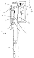
- Fig. 1 1 shows a detachable weapon, comprising at least one weapon barrel 2 with cartridge chamber 3 to which a cartridge 4 is supplied.
- a cartridge feeder consisting of a ZuGermandeckeloberteil 6 and a Zu Switzerlanddeckelunterteil 7.
- Alternative constructions of a cartridge feeder are known in the art and also feasible.
- Upper and lower parts 6, 7 of the feed cover are connected via a displaceable coupling rod 8 and a coupling piece 9 with a transmission linkage 10 and thus with an actuator 11, thus closed.
- the actuator 11 is a fuse actuator, such as a lifting element.
- An E-magnet as well as a hydraulic as well as a pneumatic cylinder are alternatives.
- the coupling piece 9 has released the locking of the delivery cover upper part 6.
- the return spring 13 is biased by the actuator 11.
- the weapon lock 5 can by Grasp the cartridge feed conveyed cartridge 4 on the bottom of the cartridge and push it into the cartridge chamber 3.
- the weapon extract 12 is free to operate.
- Fig. 2 shows the weapon 1 in firing position, but with interference, the fuse actuator 11 has failed and thus retracted at a lifting element, for example.
- Zunaturaldeckeloberteil 6 and Zutechnologydeckelunterteil 7 are still connected via the sliding coupling rod 8 and the coupling piece 9 with the transmission linkage 10 and the actuator 11 and thus opened.
- the coupling piece 9 has disabled the locking of the Zuriosdeckeloberteils 6, the return spring 13 via the transmission linkage 10 the Zu enthusiastsdeckel (upper part 6 and lower part 7) opened.
- the weapon extractor 12 is indeed operable, but missed by the position of the Zuriosdeckels in its constructive unit of upper part 6 and lower part 7 of the weapon lock 5 the cartridge bottom after shutter release.
- the shutter 5 slides in the direction of the cartridge chamber 3, but then remains in front because no shot breaks and thus the gas pressure, etc. for returning the weapon lock 5 fails.
- An (automatic) further shooting is no longer possible, an accidental shooting is prevented.
Landscapes
- Engineering & Computer Science (AREA)
- General Engineering & Computer Science (AREA)
- Aiming, Guidance, Guns With A Light Source, Armor, Camouflage, And Targets (AREA)
- Warehouses Or Storage Devices (AREA)
- Power-Operated Mechanisms For Wings (AREA)
- Toys (AREA)
Abstract
Description
- Vollautomatische gasgetriebene Waffen arbeiten in der Regel derart, dass beim Spannen der Waffe der Verschluss gegen die Federkraft einer oder mehrerer Schließfedern in eine hintere Fangposition gebracht und arretiert wird. Das Spannen erfolgt in der Regel manuell. Durch Betätigung des Abzugs wird diese Arretierung freigegeben und der Verschluss wird durch die Federkraft der Schießfeder(n) in der Verschlusslaufbahn nach vorne gebracht. Durch diese Verschlussbewegung wird einmal eine Patrone in diese Verschlusslaufbahn eingeführt, im Patronenlager am vorderen Ende der Verschlusslaufbahn verriegelt und dort gezündet. Nach Entriegelung des Verschlusses wird dieser durch den Gasdruck nach hinten in seine Fangposition gebracht und die leere Patronenhülse ausgeworfen. Der Zuführmechanismus der Patrone wird dann entweder über eine Zwangssteuerung durch den sich bewegenden Verschluss oder durch den Gasdruck beim Zünden der Munition realisiert. Eine ungewollte Schussauslösung bei gespannter Waffe durch Freigeben des Verschlusses wird häufig durch ein Sicherungselement verhindert.
- Insbesondere bei vollautomatischen Waffen ergibt sich das Problem, dass nicht ausgeschlossen werden kann, dass bei einer ferngesteuerten Sicherung der lafetierten Waffe im Störungsfall, wie Kabelbruch, Stromausfall etc., die Sicherung während des Schießvorganges betätigt wird.
- Durch Fehler an oder in der Fernsteuerung des Maschinengewehrs, beispielsweise durch Drahtbruch, Notstopp u. ä., kann es zu einer Veränderung der Bedienreihenfolge kommen, die im regulären Funktionsablauf sich aus den Funktionsschritten "Entsichern" - "Feuern" - "Feuer beenden" - "Wartezeit" - "Sichern" zusammensetzt. Die Änderung dieser Bedienreihenfolge kann ein ununterbrechbares Dauerfeuer zur Folge haben. Das ununterbrechbare Dauerfeuer kann zu kollateralen Schäden im Zielgebiet und zur Zerstörung von Maschinengewehr und Lafette als Folge schussbedingter Überlastung führen.
- Die Erfindung stellt sich die Aufgabe, eine Einrichtung in eine lafetierbare Waffe einzubinden, die bei Störung ein Weiterschießen verhindert.
- Gelöst wird die Aufgabe durch die Merkmale des Patentanspruchs 1. Vorteilhafte Ausgestaltungen sind in den Unteransprüchen aufgelistet.
- Der Erfindung liegt die grundsätzliche Idee zugrunde, im Störungsfall bzw. bei einem nicht ordnungsgemäßen Betriebszustand eine Trennung der Munition bzw. Munitionszuführung und dem Verschluss vorzunehmen. Insbesondere in derartigen Fällen wird die Patronenzuführung vom Waffenverschluss derart getrennt, dass die Patrone nicht mehr in das Patronenlager eingeführt werden kann und der Waffenverschluss in der vorderen Position verbleibt bzw. der Nachtransport unterbrochen wird. Dazu wird über eine Mechanik, beispielsweise mit Rückstelleinrichtung über ein Übertragungsgestänge, das mit einem an die Waffe eingebundenen Sicherungsaktuator der Sicherungseinrichtung funktional verbunden ist, der Zuführer aus der Bahn des Waffenverschlusses herausbefördert. Eine Rückstellfeder kann diese Aktion unterstützen. Der Waffenverschluss kann dadurch nur nach an der aus der Bahn herausbeförderten Patrone vorbei gleiten.
- In einer einfachsten Variante wird der vorhandene Aufbau eines Munitionszuführers für eine Waffe ausgenutzt. Dieser besteht bei Handfeuerwaffen in der Regel aus einem Zuführdeckel-Oberteil und einem Zuführdeckel-Unterteil. Zum Einlegen der meist gegurteten Munition wird das Deckeloberteil angeschwenkt, die Munition eingelegt und der Deckel wieder geschlossen. Das Deckelunterteil bildet die Auflagefläche für die Munitionszuführung. Um also die Trennung der Munition vom Verschluss zu erreichen, werden das Zuführoberteil sowie das Zuführunterteil derart von der Zuführung bzw. der Waffe gelöst, dass keine Munition bzw. Patrone mehr vor den Verschluss gelegt werden kann, wenn eine Störung vorliegt und beispielsweise der waffenseitige Sicherungsmagnet ausgefallen ist. In diesem Fall wird der Sicherungsaktuator der Sicherheitseinrichtung deaktiviert und über die Mechanik das Zuführunterteil angegriffen und dabei das Ober- als auch das Unterteil des Zuführers zusammen mit der dazwischen befindlichen Munition/Patrone aus der Verschlussbahn verschwenkt.
- Ein weiterer Vorteil dieser Lösung liegt darin, dass auch wenn keine Störung vorliegt, bei dieser Lösung eine zusätzliche Sicherheit dadurch besteht, dass der Zuführdeckel auf Stellung "Sicher" immer geöffnet ist.
- Die Idee läst sich grundsätzlich jedoch auch bei anderen Zuführern umsetzen.
- Soll darüber hinaus bestimmt werde, ob die Waffe sicher ist, d.h., ob der Verschluss hinten ist, oder ob die Waffe sich in einem unsicheren bzw. undefinierbaren Zustand befindet, kann dies mittels Ultraschall, einem Näherungssensor, einer Lichtschranke, durch magnetische etc. oder auch durch mechanische Lösungen realisiert werden. Zudem kann eine Kamera zugeschaltet werden, die die Stellung des Verschlusses als auch ein mögliches Vorhandensein eines Zündversagers ermitteln kann.
- Die Sicherungseinrichtung ist derart konstruktiv ausgebildet, dass die Waffe zum manuellen Schießen aus dieser Einrichtung genommen und diese separat mitgeführt werden aber auch am Fahrzeug, Objekt oder dergleichen verbleiben kann.
- Anhand eines Ausführungsbeispiels mit Zeichnung soll die Erfindung näher erläutert werden. Es zeigt:
- Fig. 1
- eine Waffe in Feuerstellung, normal,
- Fig. 2
- die Waffe in Sicherheitsstellung.
- In
Fig. 1 ist mit 1 eine lafetierbare Waffe dargestellt, aufweisend zumindest einem Waffenrohr 2 mit Patronenlager 3, dem eine Patrone 4 zugeführt wird. Das Vorlegen der Patrone 4 vor einen Waffenverschluss 5 erfolgt mittels einer Patronenzuführung, bestehend aus einem Zuführdeckeloberteil 6 und einem Zuführdeckelunterteil 7. Alternative Konstruktionen einer Patronenzuführung sind dem Fachmann bekannt und gleichfalls umsetzbar. - Ober- und Unterteil 6, 7 des Zuführdeckels sind über eine verschiebbare Kupplungsstange 8 und einem Koppelstück 9 mit einem Übertragungsgestänge 10 und damit mit einem Aktuator 11 verbunden, somit geschlossen. Mit 12 ist ein Waffenabzug und mit 13 eine Rückstellfeder gekennzeichnet. Beim Aktuator 11 handelt es sich um einen Sicherungsaktuator, wie beispielsweise um ein Hubelement. Ein E-Magnet sowie ein hydraulischer als auch pneumatischer Zylinder stellen Alternativen dar.
- Das Koppelstück 9 hat die Verriegelung des Zuführdeckels Oberteil 6 freigegeben. Die Rückstellfeder 13 ist durch den Aktuator 11 vorgespannt. Der Waffenverschluss 5 kann die durch die Patronenzuführung geförderte Patrone 4 am Patronenboden fassen und in das Patronenlager 3 schieben. Der Waffenabzug 12 ist frei zur Betätigung.
-
Fig. 2 zeigt die Waffe 1 in Feuerstellung, allerdings mit Störung, der Sicherungsaktuator 11 ist ausgefallen und damit bei einem Hubelement beispielsweise eingefahren. Zuführdeckeloberteil 6 als auch Zuführdeckelunterteil 7 sind über die verschiebbare Kupplungsstange 8 sowie über das Koppelstück 9 weiterhin mit dem Übertragungsgestänge 10 und dem Aktuator 11 verbunden und somit geöffnet. Das Koppelstück 9 hat die Verriegelung des Zuführdeckeloberteils 6 deaktiviert, die Rückstellfeder 13 über das Übertragungsgestänge 10 den Zuführerdeckel (Oberteil 6 und Unterteil 7) geöffnet. Der Waffenabzug 12 ist zwar betätigbar, doch durch die Stellung des Zuführdeckels in seiner konstruktiven Einheit von Oberteil 6 und Unterteil 7 verfehlt der Waffenverschluss 5 den Patronenboden nach Verschlussauslösung. Der Verschluss 5 gleitet in Richtung Patronenlager 3, bleibt dann aber vorne, da kein Schuss bricht und damit der Gasdruck etc. für das Zurückführen des Waffenverschlusses 5 ausbleibt. Ein (automatisches) Weiterschießen ist nicht mehr möglich, ein ungewolltes Schießen wird unterbunden.
Claims (8)
- Sicherungseinrichtung für eine lafetierbare Waffe (1) mit einem Sicherungsaktuator (11) zum fernsteuerbaren Schießen und mit einem Zuführer, durch welchen einem Waffenverschluss (5) eine Patrone (4) zugeführt und in die Verschlusslaufbahn gelegt wird, wobei die Schussauslösung vorzugsweise durch einen Waffenabzug (12) erfolgt, dadurch gekennzeichnet, dass im Störungsfall der Zuführer vom Waffenverschluss (5) getrennt wird, derart, dass die Patrone (4) nicht mehr in das Patronenlager (3) eingeführt werden kann und der Waffenverschluss (5) in der vorderen Position verbleibt bzw. der Nachtransport der Patronen (4) unterbrochen wird.
- Sicherungseinrichtung nach Anspruch 1, dadurch gekennzeichnet, dass der Zuführer über ein Übertragungsgestänge (10) mit dem Sicherungsaktuator (11) verbunden ist, sodass bei Ausfall des Sicherungsaktuators (11) der Zuführer aus der Zuführebene des Waffenverschlusses (5) herausgefördert wird.
- Sicherungseinrichtung nach Anspruch 1 oder 2, dadurch gekennzeichnet, dass der Zuführer aus einem Zuführerdeckel mit Oberteil (6) und Unterteil (7) besteht, wobei zum Einlegen der gegurteten Patronen (4) das Oberteil (6) angehoben wird.
- Sicherungseinrichtung nach einem der Ansprüche 1 bis 3, dadurch gekennzeichnet, dass der Sicherungsaktuator (11) ein Hubelement, ein E-Magnet sowie ein hydraulischer als auch pneumatischer Zylinder sein kann.
- Sicherungseinrichtung nach einem der Ansprüche 1 bis 4, dadurch gekennzeichnet, dass eine Rückstellfeder (13) über das Übertragungsgestänge (10) das Öffnen des Zuführers bzw. des Zuführdeckel (6, 7) in seiner Gesamtheit unterstützt.
- Sicherungseinrichtung nach einem der Ansprüche 1 bis 5, dadurch gekennzeichnet, dass diese derart konstruktiv ausgebildet, dass die Waffe (1) zum manuellen Schießen aus ihr genommen sowie separat mitgeführt werden aber auch am Fahrzeug, Objekt oder dergleichen verbleiben kann.
- Sicherungseinrichtung nach einem der Ansprüche 1 bis 6, dadurch gekennzeichnet, dass zusätzlich der Waffenzustand, sicher oder undefiniert der Waffe (1) bestimmt wird, was mittels Ultraschall, Näherungssensor, einer Lichtschranke, durch magnetische etc. oder auch durch mechanische Lösungen erfolgt.
- Sicherheitseinrichtung nach einem der Ansprüche 1 bis 7, dadurch gekennzeichnet, dass eine Kamera zugeschaltet werden kann, die die Stellung des Waffenverschlusses (5) als auch ein mögliches Vorhandensein eines Zündversagers im Patronenlager (3) ermitteln kann.
Applications Claiming Priority (1)
| Application Number | Priority Date | Filing Date | Title |
|---|---|---|---|
| DE200910007750 DE102009007750B3 (de) | 2009-02-06 | 2009-02-06 | Sicherheitseinrichtung einer lafetierbaren Waffe |
Publications (3)
| Publication Number | Publication Date |
|---|---|
| EP2216616A2 true EP2216616A2 (de) | 2010-08-11 |
| EP2216616A3 EP2216616A3 (de) | 2012-05-23 |
| EP2216616B1 EP2216616B1 (de) | 2013-12-11 |
Family
ID=41785936
Family Applications (1)
| Application Number | Title | Priority Date | Filing Date |
|---|---|---|---|
| EP10000147.8A Not-in-force EP2216616B1 (de) | 2009-02-06 | 2010-01-11 | Sicherheitseinrichtung einer lafetierbaren Waffe |
Country Status (3)
| Country | Link |
|---|---|
| EP (1) | EP2216616B1 (de) |
| DE (1) | DE102009007750B3 (de) |
| ES (1) | ES2450416T3 (de) |
Cited By (1)
| Publication number | Priority date | Publication date | Assignee | Title |
|---|---|---|---|---|
| US12123670B1 (en) * | 2021-01-22 | 2024-10-22 | The United States Of America As Represented By The Secretary Of The Army | Combat optimized ballistic remote armament with safety feature |
Families Citing this family (1)
| Publication number | Priority date | Publication date | Assignee | Title |
|---|---|---|---|---|
| CN109373806B (zh) * | 2018-12-12 | 2023-08-18 | 重庆建设工业(集团)有限责任公司 | 一种遥控机枪保险开闭装置 |
Family Cites Families (8)
| Publication number | Priority date | Publication date | Assignee | Title |
|---|---|---|---|---|
| GB112058A (en) * | 1917-01-16 | 1917-12-27 | Periscopes And Hyposcopes Ltd | Improvements in Means for Sighting and Manipulating Guns from Cover. |
| DE686844C (de) * | 1934-01-14 | 1940-01-17 | Rheinmetall Borsig Akt Ges | Bowdenabzugfeuerung an Lafetten fuer ruecklaufbeweglich gelagerte Maschinenwaffen |
| DE2902992C3 (de) * | 1979-01-26 | 1981-09-24 | Heckler & Koch Gmbh, 7238 Oberndorf | Lafette zur Aufnahme leichter Maschinenwaffen mit einer Umlenkvisierung |
| DE3370682D1 (en) * | 1982-09-03 | 1987-05-07 | Oerlikon Buehrle Ag | Ammunition feeder for an automatic firearm |
| DE4112959A1 (de) * | 1991-04-20 | 1992-10-22 | Mauser Werke Oberndorf | Patronen-zufuehreinrichtung |
| US5327810A (en) * | 1993-12-03 | 1994-07-12 | The United States Of America As Represented By The Secretary Of The Navy | Universal receiver having pneumatic safe/arm/firing mechanism |
| DE10215910B4 (de) * | 2002-04-11 | 2004-04-15 | Rheinmetall Landsysteme Gmbh | Vorrichtung für die Erhöhung der Sicherheit bei der Bedienung und Schußauslösung eines schweren Maschinengewehrs oder einer gleichartigen Waffe |
| DE102008025499A1 (de) * | 2007-10-08 | 2009-04-09 | Rheinmetall Landsysteme Gmbh | Ferngesteuerte Bedienung von Maschinenwaffen/-gewehren |
-
2009
- 2009-02-06 DE DE200910007750 patent/DE102009007750B3/de not_active Expired - Fee Related
-
2010
- 2010-01-11 EP EP10000147.8A patent/EP2216616B1/de not_active Not-in-force
- 2010-01-11 ES ES10000147T patent/ES2450416T3/es active Active
Non-Patent Citations (1)
| Title |
|---|
| None |
Cited By (1)
| Publication number | Priority date | Publication date | Assignee | Title |
|---|---|---|---|---|
| US12123670B1 (en) * | 2021-01-22 | 2024-10-22 | The United States Of America As Represented By The Secretary Of The Army | Combat optimized ballistic remote armament with safety feature |
Also Published As
| Publication number | Publication date |
|---|---|
| ES2450416T3 (es) | 2014-03-24 |
| DE102009007750B3 (de) | 2010-07-01 |
| EP2216616B1 (de) | 2013-12-11 |
| EP2216616A3 (de) | 2012-05-23 |
Similar Documents
| Publication | Publication Date | Title |
|---|---|---|
| EP2359084B1 (de) | Antrieb und schnellstopp für eine waffe mit vorzugsweise linearer verschluss- bzw. munitionszuführung | |
| EP1518086B1 (de) | Maschinengewehr | |
| EP1147359B1 (de) | Verschlussvorrichtung für eine handfeuerwaffe | |
| EP2406574B1 (de) | Fremd als auch eigen antreibbare waffe | |
| DE102008009827B4 (de) | Sicherungsmechanik für Waffen | |
| EP2198231B1 (de) | Antrieb für eine waffe mit vorzugsweise linearer munitionszuführung | |
| WO2017009118A2 (de) | Modulare waffe | |
| EP3014209B1 (de) | Schusswaffe | |
| EP3978859A1 (de) | Geradezugverschluss für repetierwaffen und repetierwaffe mit diesem | |
| DE2745670A1 (de) | Abzugssicherung fuer schusswaffen | |
| EP2216616B1 (de) | Sicherheitseinrichtung einer lafetierbaren Waffe | |
| DE19732857C1 (de) | Spannabzugseinrichtung mit einer Hammersicherung | |
| DE102011106200B4 (de) | Schlagbolzensicherung | |
| EP3390949B1 (de) | Spannvorrichtung für einen schlagbolzen sowie waffe mit der spannvorrichtung | |
| EP2048467B1 (de) | Abfeuerunterbrechung für insbesondere automatische Maschinenwaffen | |
| EP0252902B1 (de) | Schusswaffe | |
| DE2224847C3 (de) | Rückstoßfreie Panzerabwehrwaffe | |
| EP2049863B1 (de) | Vorrichtung zur auslösung eines schlagbolzens | |
| DE1809699A1 (de) | Verbesserte Vorrichtung zur Verhinderung einer doppelten Munitionszufuehrung | |
| DE102016012145A1 (de) | Revolverkanone und Verfahren zum Betrieb einer Revolverkanone | |
| DE2403477C2 (de) | Verschlußfangeinrichtung für fernbediente, automatische Feuerwaffen | |
| DE139766C (de) | Selbsttätige Feuerwaffe mit gleitendem Lauf | |
| EP4018149B1 (de) | Verschlusssystem und rohrwaffe | |
| EP3961143A1 (de) | Patronenzuführvorrichtung | |
| DE9405724U1 (de) | Gaspistole mit Sicherung zum Verhindern einer Zuladung scharfer Munition |
Legal Events
| Date | Code | Title | Description |
|---|---|---|---|
| PUAI | Public reference made under article 153(3) epc to a published international application that has entered the european phase |
Free format text: ORIGINAL CODE: 0009012 |
|
| AK | Designated contracting states |
Kind code of ref document: A2 Designated state(s): AT BE BG CH CY CZ DE DK EE ES FI FR GB GR HR HU IE IS IT LI LT LU LV MC MK MT NL NO PL PT RO SE SI SK SM TR |
|
| AX | Request for extension of the european patent |
Extension state: AL BA RS |
|
| PUAL | Search report despatched |
Free format text: ORIGINAL CODE: 0009013 |
|
| AK | Designated contracting states |
Kind code of ref document: A3 Designated state(s): AT BE BG CH CY CZ DE DK EE ES FI FR GB GR HR HU IE IS IT LI LT LU LV MC MK MT NL NO PL PT RO SE SI SK SM TR |
|
| AX | Request for extension of the european patent |
Extension state: AL BA RS |
|
| RIC1 | Information provided on ipc code assigned before grant |
Ipc: F41A 19/08 20060101ALI20120417BHEP Ipc: F41A 17/42 20060101ALN20120417BHEP Ipc: F41A 17/06 20060101AFI20120417BHEP |
|
| 17P | Request for examination filed |
Effective date: 20121123 |
|
| GRAP | Despatch of communication of intention to grant a patent |
Free format text: ORIGINAL CODE: EPIDOSNIGR1 |
|
| RIC1 | Information provided on ipc code assigned before grant |
Ipc: F41A 17/06 20060101AFI20130530BHEP Ipc: F41A 17/42 20060101ALN20130530BHEP Ipc: F41A 19/08 20060101ALI20130530BHEP |
|
| INTG | Intention to grant announced |
Effective date: 20130620 |
|
| GRAS | Grant fee paid |
Free format text: ORIGINAL CODE: EPIDOSNIGR3 |
|
| GRAA | (expected) grant |
Free format text: ORIGINAL CODE: 0009210 |
|
| RAP1 | Party data changed (applicant data changed or rights of an application transferred) |
Owner name: RHEINMETALL LANDSYSTEME GMBH |
|
| AK | Designated contracting states |
Kind code of ref document: B1 Designated state(s): AT BE BG CH CY CZ DE DK EE ES FI FR GB GR HR HU IE IS IT LI LT LU LV MC MK MT NL NO PL PT RO SE SI SK SM TR |
|
| REG | Reference to a national code |
Ref country code: GB Ref legal event code: FG4D Free format text: NOT ENGLISH |
|
| REG | Reference to a national code |
Ref country code: CH Ref legal event code: EP |
|
| REG | Reference to a national code |
Ref country code: AT Ref legal event code: REF Ref document number: 644809 Country of ref document: AT Kind code of ref document: T Effective date: 20140115 |
|
| REG | Reference to a national code |
Ref country code: IE Ref legal event code: FG4D Free format text: LANGUAGE OF EP DOCUMENT: GERMAN |
|
| REG | Reference to a national code |
Ref country code: DE Ref legal event code: R096 Ref document number: 502010005581 Country of ref document: DE Effective date: 20140206 |
|
| REG | Reference to a national code |
Ref country code: ES Ref legal event code: FG2A Ref document number: 2450416 Country of ref document: ES Kind code of ref document: T3 Effective date: 20140324 |
|
| REG | Reference to a national code |
Ref country code: NL Ref legal event code: VDEP Effective date: 20131211 |
|
| PG25 | Lapsed in a contracting state [announced via postgrant information from national office to epo] |
Ref country code: HR Free format text: LAPSE BECAUSE OF FAILURE TO SUBMIT A TRANSLATION OF THE DESCRIPTION OR TO PAY THE FEE WITHIN THE PRESCRIBED TIME-LIMIT Effective date: 20131211 Ref country code: NO Free format text: LAPSE BECAUSE OF FAILURE TO SUBMIT A TRANSLATION OF THE DESCRIPTION OR TO PAY THE FEE WITHIN THE PRESCRIBED TIME-LIMIT Effective date: 20140311 Ref country code: FI Free format text: LAPSE BECAUSE OF FAILURE TO SUBMIT A TRANSLATION OF THE DESCRIPTION OR TO PAY THE FEE WITHIN THE PRESCRIBED TIME-LIMIT Effective date: 20131211 Ref country code: NL Free format text: LAPSE BECAUSE OF FAILURE TO SUBMIT A TRANSLATION OF THE DESCRIPTION OR TO PAY THE FEE WITHIN THE PRESCRIBED TIME-LIMIT Effective date: 20131211 Ref country code: LT Free format text: LAPSE BECAUSE OF FAILURE TO SUBMIT A TRANSLATION OF THE DESCRIPTION OR TO PAY THE FEE WITHIN THE PRESCRIBED TIME-LIMIT Effective date: 20131211 Ref country code: SE Free format text: LAPSE BECAUSE OF FAILURE TO SUBMIT A TRANSLATION OF THE DESCRIPTION OR TO PAY THE FEE WITHIN THE PRESCRIBED TIME-LIMIT Effective date: 20131211 |
|
| REG | Reference to a national code |
Ref country code: LT Ref legal event code: MG4D |
|
| PG25 | Lapsed in a contracting state [announced via postgrant information from national office to epo] |
Ref country code: CY Free format text: LAPSE BECAUSE OF FAILURE TO SUBMIT A TRANSLATION OF THE DESCRIPTION OR TO PAY THE FEE WITHIN THE PRESCRIBED TIME-LIMIT Effective date: 20131211 Ref country code: LV Free format text: LAPSE BECAUSE OF FAILURE TO SUBMIT A TRANSLATION OF THE DESCRIPTION OR TO PAY THE FEE WITHIN THE PRESCRIBED TIME-LIMIT Effective date: 20131211 |
|
| PG25 | Lapsed in a contracting state [announced via postgrant information from national office to epo] |
Ref country code: IS Free format text: LAPSE BECAUSE OF FAILURE TO SUBMIT A TRANSLATION OF THE DESCRIPTION OR TO PAY THE FEE WITHIN THE PRESCRIBED TIME-LIMIT Effective date: 20140411 Ref country code: EE Free format text: LAPSE BECAUSE OF FAILURE TO SUBMIT A TRANSLATION OF THE DESCRIPTION OR TO PAY THE FEE WITHIN THE PRESCRIBED TIME-LIMIT Effective date: 20131211 |
|
| PG25 | Lapsed in a contracting state [announced via postgrant information from national office to epo] |
Ref country code: PT Free format text: LAPSE BECAUSE OF FAILURE TO SUBMIT A TRANSLATION OF THE DESCRIPTION OR TO PAY THE FEE WITHIN THE PRESCRIBED TIME-LIMIT Effective date: 20140411 Ref country code: PL Free format text: LAPSE BECAUSE OF FAILURE TO SUBMIT A TRANSLATION OF THE DESCRIPTION OR TO PAY THE FEE WITHIN THE PRESCRIBED TIME-LIMIT Effective date: 20131211 Ref country code: SK Free format text: LAPSE BECAUSE OF FAILURE TO SUBMIT A TRANSLATION OF THE DESCRIPTION OR TO PAY THE FEE WITHIN THE PRESCRIBED TIME-LIMIT Effective date: 20131211 Ref country code: LU Free format text: LAPSE BECAUSE OF FAILURE TO SUBMIT A TRANSLATION OF THE DESCRIPTION OR TO PAY THE FEE WITHIN THE PRESCRIBED TIME-LIMIT Effective date: 20140111 Ref country code: RO Free format text: LAPSE BECAUSE OF FAILURE TO SUBMIT A TRANSLATION OF THE DESCRIPTION OR TO PAY THE FEE WITHIN THE PRESCRIBED TIME-LIMIT Effective date: 20131211 |
|
| REG | Reference to a national code |
Ref country code: CH Ref legal event code: PL |
|
| REG | Reference to a national code |
Ref country code: DE Ref legal event code: R097 Ref document number: 502010005581 Country of ref document: DE |
|
| PG25 | Lapsed in a contracting state [announced via postgrant information from national office to epo] |
Ref country code: MC Free format text: LAPSE BECAUSE OF FAILURE TO SUBMIT A TRANSLATION OF THE DESCRIPTION OR TO PAY THE FEE WITHIN THE PRESCRIBED TIME-LIMIT Effective date: 20131211 |
|
| PLBE | No opposition filed within time limit |
Free format text: ORIGINAL CODE: 0009261 |
|
| STAA | Information on the status of an ep patent application or granted ep patent |
Free format text: STATUS: NO OPPOSITION FILED WITHIN TIME LIMIT |
|
| PG25 | Lapsed in a contracting state [announced via postgrant information from national office to epo] |
Ref country code: LI Free format text: LAPSE BECAUSE OF NON-PAYMENT OF DUE FEES Effective date: 20140131 Ref country code: DK Free format text: LAPSE BECAUSE OF FAILURE TO SUBMIT A TRANSLATION OF THE DESCRIPTION OR TO PAY THE FEE WITHIN THE PRESCRIBED TIME-LIMIT Effective date: 20131211 Ref country code: CH Free format text: LAPSE BECAUSE OF NON-PAYMENT OF DUE FEES Effective date: 20140131 |
|
| REG | Reference to a national code |
Ref country code: IE Ref legal event code: MM4A |
|
| 26N | No opposition filed |
Effective date: 20140912 |
|
| GBPC | Gb: european patent ceased through non-payment of renewal fee |
Effective date: 20140311 |
|
| REG | Reference to a national code |
Ref country code: DE Ref legal event code: R097 Ref document number: 502010005581 Country of ref document: DE Effective date: 20140912 |
|
| PG25 | Lapsed in a contracting state [announced via postgrant information from national office to epo] |
Ref country code: GB Free format text: LAPSE BECAUSE OF NON-PAYMENT OF DUE FEES Effective date: 20140311 Ref country code: IE Free format text: LAPSE BECAUSE OF NON-PAYMENT OF DUE FEES Effective date: 20140111 |
|
| PG25 | Lapsed in a contracting state [announced via postgrant information from national office to epo] |
Ref country code: SI Free format text: LAPSE BECAUSE OF FAILURE TO SUBMIT A TRANSLATION OF THE DESCRIPTION OR TO PAY THE FEE WITHIN THE PRESCRIBED TIME-LIMIT Effective date: 20131211 |
|
| REG | Reference to a national code |
Ref country code: FR Ref legal event code: PLFP Year of fee payment: 7 |
|
| PG25 | Lapsed in a contracting state [announced via postgrant information from national office to epo] |
Ref country code: MT Free format text: LAPSE BECAUSE OF FAILURE TO SUBMIT A TRANSLATION OF THE DESCRIPTION OR TO PAY THE FEE WITHIN THE PRESCRIBED TIME-LIMIT Effective date: 20131211 |
|
| REG | Reference to a national code |
Ref country code: AT Ref legal event code: MM01 Ref document number: 644809 Country of ref document: AT Kind code of ref document: T Effective date: 20150111 |
|
| PG25 | Lapsed in a contracting state [announced via postgrant information from national office to epo] |
Ref country code: SM Free format text: LAPSE BECAUSE OF FAILURE TO SUBMIT A TRANSLATION OF THE DESCRIPTION OR TO PAY THE FEE WITHIN THE PRESCRIBED TIME-LIMIT Effective date: 20131211 |
|
| PGFP | Annual fee paid to national office [announced via postgrant information from national office to epo] |
Ref country code: DE Payment date: 20160120 Year of fee payment: 7 Ref country code: ES Payment date: 20160112 Year of fee payment: 7 |
|
| PG25 | Lapsed in a contracting state [announced via postgrant information from national office to epo] |
Ref country code: AT Free format text: LAPSE BECAUSE OF NON-PAYMENT OF DUE FEES Effective date: 20150111 |
|
| PGFP | Annual fee paid to national office [announced via postgrant information from national office to epo] |
Ref country code: FR Payment date: 20160121 Year of fee payment: 7 Ref country code: BE Payment date: 20160120 Year of fee payment: 7 |
|
| PG25 | Lapsed in a contracting state [announced via postgrant information from national office to epo] |
Ref country code: GR Free format text: LAPSE BECAUSE OF FAILURE TO SUBMIT A TRANSLATION OF THE DESCRIPTION OR TO PAY THE FEE WITHIN THE PRESCRIBED TIME-LIMIT Effective date: 20140312 Ref country code: BG Free format text: LAPSE BECAUSE OF FAILURE TO SUBMIT A TRANSLATION OF THE DESCRIPTION OR TO PAY THE FEE WITHIN THE PRESCRIBED TIME-LIMIT Effective date: 20131211 Ref country code: IT Free format text: LAPSE BECAUSE OF FAILURE TO SUBMIT A TRANSLATION OF THE DESCRIPTION OR TO PAY THE FEE WITHIN THE PRESCRIBED TIME-LIMIT Effective date: 20131211 |
|
| PG25 | Lapsed in a contracting state [announced via postgrant information from national office to epo] |
Ref country code: HU Free format text: LAPSE BECAUSE OF FAILURE TO SUBMIT A TRANSLATION OF THE DESCRIPTION OR TO PAY THE FEE WITHIN THE PRESCRIBED TIME-LIMIT; INVALID AB INITIO Effective date: 20100111 Ref country code: TR Free format text: LAPSE BECAUSE OF FAILURE TO SUBMIT A TRANSLATION OF THE DESCRIPTION OR TO PAY THE FEE WITHIN THE PRESCRIBED TIME-LIMIT Effective date: 20131211 |
|
| PG25 | Lapsed in a contracting state [announced via postgrant information from national office to epo] |
Ref country code: BE Free format text: LAPSE BECAUSE OF NON-PAYMENT OF DUE FEES Effective date: 20170131 |
|
| PGFP | Annual fee paid to national office [announced via postgrant information from national office to epo] |
Ref country code: CZ Payment date: 20170110 Year of fee payment: 8 |
|
| REG | Reference to a national code |
Ref country code: DE Ref legal event code: R119 Ref document number: 502010005581 Country of ref document: DE |
|
| REG | Reference to a national code |
Ref country code: FR Ref legal event code: ST Effective date: 20170929 |
|
| PG25 | Lapsed in a contracting state [announced via postgrant information from national office to epo] |
Ref country code: FR Free format text: LAPSE BECAUSE OF NON-PAYMENT OF DUE FEES Effective date: 20170131 |
|
| PG25 | Lapsed in a contracting state [announced via postgrant information from national office to epo] |
Ref country code: DE Free format text: LAPSE BECAUSE OF NON-PAYMENT OF DUE FEES Effective date: 20170801 |
|
| REG | Reference to a national code |
Ref country code: BE Ref legal event code: MM Effective date: 20170131 |
|
| PG25 | Lapsed in a contracting state [announced via postgrant information from national office to epo] |
Ref country code: ES Free format text: LAPSE BECAUSE OF NON-PAYMENT OF DUE FEES Effective date: 20170112 |
|
| PG25 | Lapsed in a contracting state [announced via postgrant information from national office to epo] |
Ref country code: MK Free format text: LAPSE BECAUSE OF FAILURE TO SUBMIT A TRANSLATION OF THE DESCRIPTION OR TO PAY THE FEE WITHIN THE PRESCRIBED TIME-LIMIT Effective date: 20131211 |
|
| REG | Reference to a national code |
Ref country code: ES Ref legal event code: FD2A Effective date: 20181112 |
|
| PG25 | Lapsed in a contracting state [announced via postgrant information from national office to epo] |
Ref country code: CZ Free format text: LAPSE BECAUSE OF NON-PAYMENT OF DUE FEES Effective date: 20180111 |