EP2216575B1 - Elément de fixation, dispositif ainsi que procédé de fixation d'un tuyau flexible - Google Patents
Elément de fixation, dispositif ainsi que procédé de fixation d'un tuyau flexible Download PDFInfo
- Publication number
- EP2216575B1 EP2216575B1 EP10000973.7A EP10000973A EP2216575B1 EP 2216575 B1 EP2216575 B1 EP 2216575B1 EP 10000973 A EP10000973 A EP 10000973A EP 2216575 B1 EP2216575 B1 EP 2216575B1
- Authority
- EP
- European Patent Office
- Prior art keywords
- leg
- pipe
- recess
- legs
- tube
- Prior art date
- Legal status (The legal status is an assumption and is not a legal conclusion. Google has not performed a legal analysis and makes no representation as to the accuracy of the status listed.)
- Not-in-force
Links
Images


Classifications
-
- F—MECHANICAL ENGINEERING; LIGHTING; HEATING; WEAPONS; BLASTING
- F16—ENGINEERING ELEMENTS AND UNITS; GENERAL MEASURES FOR PRODUCING AND MAINTAINING EFFECTIVE FUNCTIONING OF MACHINES OR INSTALLATIONS; THERMAL INSULATION IN GENERAL
- F16L—PIPES; JOINTS OR FITTINGS FOR PIPES; SUPPORTS FOR PIPES, CABLES OR PROTECTIVE TUBING; MEANS FOR THERMAL INSULATION IN GENERAL
- F16L3/00—Supports for pipes, cables or protective tubing, e.g. hangers, holders, clamps, cleats, clips, brackets
- F16L3/08—Supports for pipes, cables or protective tubing, e.g. hangers, holders, clamps, cleats, clips, brackets substantially surrounding the pipe, cable or protective tubing
- F16L3/12—Supports for pipes, cables or protective tubing, e.g. hangers, holders, clamps, cleats, clips, brackets substantially surrounding the pipe, cable or protective tubing comprising a member substantially surrounding the pipe, cable or protective tubing
- F16L3/1226—Supports for pipes, cables or protective tubing, e.g. hangers, holders, clamps, cleats, clips, brackets substantially surrounding the pipe, cable or protective tubing comprising a member substantially surrounding the pipe, cable or protective tubing elongated supports, e.g. to support a curved pipe
-
- F—MECHANICAL ENGINEERING; LIGHTING; HEATING; WEAPONS; BLASTING
- F16—ENGINEERING ELEMENTS AND UNITS; GENERAL MEASURES FOR PRODUCING AND MAINTAINING EFFECTIVE FUNCTIONING OF MACHINES OR INSTALLATIONS; THERMAL INSULATION IN GENERAL
- F16L—PIPES; JOINTS OR FITTINGS FOR PIPES; SUPPORTS FOR PIPES, CABLES OR PROTECTIVE TUBING; MEANS FOR THERMAL INSULATION IN GENERAL
- F16L3/00—Supports for pipes, cables or protective tubing, e.g. hangers, holders, clamps, cleats, clips, brackets
- F16L3/08—Supports for pipes, cables or protective tubing, e.g. hangers, holders, clamps, cleats, clips, brackets substantially surrounding the pipe, cable or protective tubing
- F16L3/12—Supports for pipes, cables or protective tubing, e.g. hangers, holders, clamps, cleats, clips, brackets substantially surrounding the pipe, cable or protective tubing comprising a member substantially surrounding the pipe, cable or protective tubing
- F16L3/13—Supports for pipes, cables or protective tubing, e.g. hangers, holders, clamps, cleats, clips, brackets substantially surrounding the pipe, cable or protective tubing comprising a member substantially surrounding the pipe, cable or protective tubing and engaging it by snap action
-
- F—MECHANICAL ENGINEERING; LIGHTING; HEATING; WEAPONS; BLASTING
- F16—ENGINEERING ELEMENTS AND UNITS; GENERAL MEASURES FOR PRODUCING AND MAINTAINING EFFECTIVE FUNCTIONING OF MACHINES OR INSTALLATIONS; THERMAL INSULATION IN GENERAL
- F16L—PIPES; JOINTS OR FITTINGS FOR PIPES; SUPPORTS FOR PIPES, CABLES OR PROTECTIVE TUBING; MEANS FOR THERMAL INSULATION IN GENERAL
- F16L3/00—Supports for pipes, cables or protective tubing, e.g. hangers, holders, clamps, cleats, clips, brackets
- F16L3/08—Supports for pipes, cables or protective tubing, e.g. hangers, holders, clamps, cleats, clips, brackets substantially surrounding the pipe, cable or protective tubing
- F16L3/12—Supports for pipes, cables or protective tubing, e.g. hangers, holders, clamps, cleats, clips, brackets substantially surrounding the pipe, cable or protective tubing comprising a member substantially surrounding the pipe, cable or protective tubing
- F16L3/137—Supports for pipes, cables or protective tubing, e.g. hangers, holders, clamps, cleats, clips, brackets substantially surrounding the pipe, cable or protective tubing comprising a member substantially surrounding the pipe, cable or protective tubing and consisting of a flexible band
-
- F—MECHANICAL ENGINEERING; LIGHTING; HEATING; WEAPONS; BLASTING
- F16—ENGINEERING ELEMENTS AND UNITS; GENERAL MEASURES FOR PRODUCING AND MAINTAINING EFFECTIVE FUNCTIONING OF MACHINES OR INSTALLATIONS; THERMAL INSULATION IN GENERAL
- F16L—PIPES; JOINTS OR FITTINGS FOR PIPES; SUPPORTS FOR PIPES, CABLES OR PROTECTIVE TUBING; MEANS FOR THERMAL INSULATION IN GENERAL
- F16L43/00—Bends; Siphons
- F16L43/02—Bends; Siphons adapted to make use of special securing means
-
- F—MECHANICAL ENGINEERING; LIGHTING; HEATING; WEAPONS; BLASTING
- F24—HEATING; RANGES; VENTILATING
- F24F—AIR-CONDITIONING; AIR-HUMIDIFICATION; VENTILATION; USE OF AIR CURRENTS FOR SCREENING
- F24F13/00—Details common to, or for air-conditioning, air-humidification, ventilation or use of air currents for screening
- F24F13/02—Ducting arrangements
- F24F13/0254—Ducting arrangements characterised by their mounting means, e.g. supports
Definitions
- the invention relates to a fastening element, a device and a method for attaching a flexible tube, in particular a flexible corrugated tube, to an object, in particular a wall, ceiling or the like, with a pipe attachment.
- Fasteners, devices and methods of the type mentioned are known in the art for a long time, sieche eg US Pat. No. 6,409,223 . WO 2006/134 266 . US 2008/0035799 .
- the well-known fastener is the so-called pipe clamp, which consists essentially of two enclosing the pipe ring-shaped sheet metal parts.
- One of the sheet metal parts is first mounted on the object or on the wall such that the ring-segment-shaped sheet metal part forms a tube receiving, in which the tube can be inserted.
- the sheet metal parts each have at a first free end connecting means, which allows a positive connection of the sheet metal parts together at the free ends, which usually one sheet metal part on the sheet metal part already attached to the wall can be arranged at one end such that the pipe receiving freely remains accessible.
- the tube is inserted into the tube receiving, the second sheet metal part folded such that its second free end opposite to the second free end of the wall-mounted sheet metal part and connected thereto by means of a screw.
- a pipe attachment is formed by screwing the second sheet metal part to the first sheet metal part.
- the known fasteners have the disadvantage that a fitter hold the pipe during assembly, move the second sheet metal part to close the pipe clamp, align and screwed to the other sheet metal part. For a single mechanic, this is sometimes tedious and complicated.
- the pipe clamps can easily twist on the object or on the wall, since they are fixed with only a single screw on the wall, so that they can be easily rotated about the axis of the screw.
- a change in direction of the pipe to be laid for example, when the pipe is to be attached to a certain curved path following the object or on the wall, this quickly leads to problems.
- the invention is therefore an object of the invention to provide a fastener, an apparatus and a method for attaching a flexible tube to an object, which allows a simple and cost-effective manner easy attachment of the tube.
- the fastener as an at least two legs exhibiting angle element, wherein the pipe attachment is designed as open-edged recess with a rear engaging the diameter of the pipe enabling undercut in at least one of the legs.
- the pipe attachment is designed as open-edged recess with a rear engaging the diameter of the pipe enabling undercut in at least one of the legs.
- an angle element provided, which has at least two legs. This is easy and inexpensive to produce.
- an open-edged recess is formed, which serves as a pipe attachment.
- the flexible tube can be radially - with respect to the pipe - introduced.
- the recess in this case has an undercut, which allows engaging behind the diameter of the tube.
- the recess expediently has a taper in the edge region, so seen in the mounting direction, the recess is formed wider at least behind the taper.
- the undercut is designed such that it allows engaging behind the diameter of the tube, which means that an introduced into the recess pipe is partially engaged behind by the undercut.
- it is introduced radially into the recess, wherein due to the undercut the cross section of the flexible tube is first deformed elastically, so that the tube passes through the narrowed by the tapered input area.
- the flexible tube relaxes so that it at least essentially retains its original cross-sectional shape.
- the tube is clipped into the open-edged recess. Due to the advantageous undercut, the pipe can not be easily detached from the pipe attachment. As a result, the attachment of the flexible tube is considerably simplified. An installer must now only attach the angle element with the recess not having legs on the object and then can In a simple way, clip the flexible tube into the open-edged recess so that the undercut engages behind the tube. The tube can thus be easily and securely attached to the object with a few assembly steps.
- the first leg having the recess is arranged perpendicularly or substantially perpendicular to the second leg, so that the tube can be guided parallel to the object and securely seated in the recess.
- the recess is formed substantially circular, so that the contour of the recess substantially corresponds to that of the pipe to be fastened, whereby a secure hold is ensured.
- any other arbitrary cross-sectional shape of the recess is also conceivable, provided that it has an undercut as described above.
- the shape of the recess does not necessarily correspond to the cross-sectional shape of the tube.
- At least one, preferably a plurality of openings for a screw or the like is formed in the second leg.
- the screw can then be screwed into the article or into the wall or into a wall provided in the dowel, and thus the angle element or the fastener are attached to the object. If two openings are provided, in addition, the orientation of the fastener to the object are defined precisely. A rotation of the fastener during assembly of the tube is then no longer possible, whereby in particular the assembly of a tube along a curve or curve is simplified.
- a third leg is provided, which is designed as a side leg and has at least one opening for a screw or the like.
- the third leg is thus arranged laterally and is preferably either from the first, the pipe attachment having legs or from the second leg.
- the orientation of the pipe attachment or the recess can be varied as needed.
- the orientation of the recess is vertical or horizontal.
- the same fastening element can be used both for fastening the pipe to a ceiling and to a wall extending perpendicularly thereto or oriented, the pipe always being held securely in the open-edged recess.
- At least one of the openings is formed slot-like.
- holes may first be drilled in the wall holding the fastener. Frequently, however, such holes are not sufficiently accurately introduced into the wall, so that by means of the slot-like opening a readjustment of the fastener can be made. Under certain conditions, such a readjustment of the orientation or Arrangement of the fastener on the object even after insertion of the flexible tube in the pipe attachment possible.
- the angle element has at least one notch on both sides, in particular in the bending region, in particular between the first and the second leg, for a tube-engaging tubular holding means.
- the angle element thus has on both sides notches on between the first and the second leg.
- At least one fastening tab for a loop-shaped holding means is arranged in the second leg.
- the fastening tab is disposed close to the first leg so that the loop-shaped retaining means can be hooked around the tube and the first leg and into the fastening tab.
- the tube can be securely locked permanently to the fastening element in a simple manner.
- the fastening strap is formed as a fastening tongue bent out of the second leg.
- the fastening tongue is in the manufacture of the Angle element initially cut out of the full material in particular three sides and then bent out accordingly.
- the free end of the fastening tongue is expediently oriented in a pioneering manner by the first leg, so that the tube or the loop-shaped retaining means can be securely held thereon.
- the material of the angle element is formed substantially as thick as a shaft gap of the corrugated pipe.
- the height of a cross section through the angle element substantially corresponds to the space formed between two adjacent corrugations of the corrugated tube.
- the corrugated tube can also be held without play (axially) in the recess.
- the angle element is formed substantially U-shaped, so that the first and the fourth leg are aligned with each other, whereby a double pipe attachment to the one fastener is offered.
- the third leg is optional.
- the second leg is at least partially bent such that the first and the fourth leg are aligned at an angle, in particular perpendicular to each other.
- the second or middle leg is thus bent by a certain angle, more preferably it has a bending edge.
- the legs of an angle element are themselves flat and have a corresponding bending edge only at their end associated with the adjacent leg.
- the fastener can be used as an angle fastener or curve fastener. Due to the predetermined orientation of the two legs having the pipe attachment (first and third leg) the tube or the corrugated pipe is given a certain angle or radius.
- Such an angle fastening element can be used, for example, in the transition from a ceiling to a wall extending perpendicular thereto.
- the angle element is designed as an angle plate. Thus, a stable and reliable pipe mounting is possible.
- the fastening element may be formed as a stamped and bent part.
- the angle element or the angle plate is first cut or punched from a flat sheet metal part and then the legs are bent into the desired orientation or the angle element in the desired shape. This can be done particularly advantageously in a single processing step, so that the fastener is particularly easy and inexpensive to produce.
- the device according to the invention is characterized by at least two fastening elements, which are formed as described above, and are pivotally connected to each other by means of a rotary joint.
- the device according to the invention thus provides by means of the rotary joint pivotally interconnected fasteners, wherein the angle is either preset or adjustable by the fitter on site.
- the hinge allows easy adjustment and, in particular, optionally a continuous adjustment of the orientation of the fasteners to each other, so that the device is adaptable to any need.
- the hinge is arranged on an opposite end of the respective first leg of the second leg.
- the fastening elements expediently each have only one (first) leg having the pipe fastening according to the invention, so that the fastening elements themselves are essentially L-shaped.
- the rotary joint is provided at the remote to the pipe attachment end of the respective fastening or angular element.
- the fastening elements can be scissored-like interlocked or twisted, so that the fastening elements are displaceable in a plane to each other, or folded along an edge to each other, for example, that the device receives a W-shape (with substantially right angles) ,
- the rotary joint is formed by one of the superimposed second leg interconnecting blind rivets. It is thus provided that initially the two second legs of the two fastening elements rest on one another.
- the blind rivets interconnecting the two second legs therefore forms a particularly simple and cost-effective way of ensuring an angular adjustment between the two fastening elements.
- the blind rivets defines an axis of rotation about which the fasteners can be pivoted.
- each of the second leg at least one Einstellschraubenö réelle on a coaxial with the axis of rotation of the rotary joint or the blind rivets aligned - imaginary - circle.
- the Einstellschraubenö réelle of the respective leg is thus on an (imaginary) circle around the axis of rotation of the rotary joint, so that when the fasteners are rotated or pivoted to each other, the Einstellschraubenö réelleen the two legs in a certain position of the legs are aligned with each other.
- the device can be locked to one another in a certain angular position of the fastening elements by inserting an adjusting screw or a setting pin.
- an adjusting screw or a setting pin Conveniently, in the one or more Einstellschraubenötechnische one of the legs threaded, into which the adjusting screw can be screwed.
- different numbers of differently sized setting angles between the fastening elements can be fixed or adjusted.
- the upper second leg has two Einstellschraubenö réelleen and the underlying second leg at least two Einstellschraubenö réelleen.
- the lower second leg has a plurality of Einstellschraubenö réelleen.
- the Einstellschraubenö réelleen both second legs are preferably equally spaced in each case over at least one angular range arranged on the circle. This means that the Einstellschraubenö réelleen a second leg have the same distance or angular distance from each other.
- the third legs of the fasteners are arranged on the same side of the device.
- the device can for example be arranged on a corner of a wall in such a way that it can be fastened to the wall by means of the side limbs and a tube can be introduced into the tube fastening from above.
- a tube can be introduced into the tube fastening from above.
- the conduit system according to the invention for liquid and / or gaseous substances, by the course, of course, cables can be performed, is characterized in that the fastening element and / or the device for fixing a flexible tube are formed as described above. This allows a person skilled in the art a particularly simple and quick installation of the flexible Pipe also in difficult places, such as the transition from a wall to a sloping roof.
- the tube is formed as a corrugated tube.
- the contour of the recess of the fastening element substantially corresponds to the cross section of the corrugated pipe in a shaft intermediate space.
- the corrugated tube is in the introduced into the recess and thus relaxed state on the inside of the recess surface, whereby, for example, rattling noises or the like can be prevented.
- a secure hold of the corrugated pipe is guaranteed in the pipe attachment.
- the cross section of the corrugated tube is formed substantially annular or oval ring-shaped. Accordingly, the contour of the recess is selected as described above. Conveniently, the diameter of the recess is only slightly larger than that of the shaft gap, so on the one hand, a secure fit is ensured and on the other hand, the materials of the corrugated pipe and / or the attachment or angle element are not permanently loaded. Alternatively, (corrugated) pipe and / or pipe attachment can be designed to produce a press fit.
- the thickness of the material of the angle element substantially corresponds to the width of a shaft gap of the corrugated pipe.
- At least one loop-shaped holding means in particular a cable tie, wire or the like is provided, which engages around the tube and cooperates with the notches and / or with the fastening tab.
- the holding means can be attached as an additional securing element in order to prevent detachment from the device or from the fastening element, for example, in the case of particularly heavy pipes or heavily loaded pipes.
- the inventive method provides that the tube is introduced substantially radially into the recess with elastic deformation of the tube cross-section, so that the completely inserted into the recess tube deformed back into its original shape due to its inherent elasticity and thereby the undercut of the recess engages behind the diameter of the tube , In other words, it is provided that the tube is clipped into the recess.
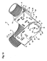
- FIGS. 1 to 3 each show in a perspective view a fastener 1 for fixing a flexible tube 2, which is designed here as a flexible corrugated tube 3, wherein the three figures show the attachment process of the corrugated tube 3 to the fastener 1.
- the fastening element 1 is formed as an angle element 4, which has two legs 5, 6, which are arranged substantially perpendicular to each other.
- the legs 5, 6 themselves are flat.
- the angle element is designed as an angle plate 7, so that the angle between the two legs 5 and 6 in a simple manner by bending or forming can be created.
- the fastening element 1 furthermore has a pipe attachment 8, which serves for fastening the pipe 2 to the fastening element 1.
- the pipe attachment 8 is formed as an open-edged recess 9 in the first leg 5.
- the recess 9 is formed open to an edge of the angle element 4 and the leg 5 out.
- the recess 9 in the direction of the longitudinal extension of the angle element 4th aligned.
- the recess 9 has a substantially circular contour, wherein the center of the circle is within the first leg 5, so that the recess 9 to the edge 10 of the leg 5, to which the recess 9 is formed open tapers and forms an undercut 11.
- the fastening element 1 or the angle element 4 in the bending region between the two legs 5 and 6 on both sides notch 12, to be discussed in more detail later.
- the flexible corrugated tube 3 which is shown here cut, has a wavy longitudinal section, wherein the "waves" 13 in the present embodiment each ring once over the entire circumference of the tube 2 extend and evenly spaced from each other over the tube 2 are distributed ,
- the shafts 13 of the corrugated tube 3 can also be arranged obliquely or even helical or thread-shaped. Between two adjacent shafts 13, a shaft gap 14 is formed in each case whose outer diameter is smaller than that of the shafts 13.
- the diameter D 1 of the open-edged recess 9 substantially corresponds to the diameter of the corrugated tube 3 in a shaft intermediate space 14.
- FIG. 1 shows the corrugated tube 3 before introduction into the open-edged recess 9.
- the corrugated pipe is introduced radially in the direction of an arrow 15 in the recess 9 until it with a shaft space 14 on both sides on the edge 10 of the first leg 5 rests. Due to the rear grip, the radial inlet opening is narrower than the diameter D1, so that the corrugated tube 3 can not easily be introduced into the recess 9.
- the corrugated tube 3 is squeezed into the recess 9 with elastic deformation of the corrugated tube 3.
- the corrugated tube 3 is replaced in this state an oval cross-section.
- the corrugated tube 3 If the corrugated tube 3 is completely inserted into the recess 9 in the direction of the arrow 15, then the corrugated tube 3 assumes its original (cross-sectional) shape due to its inherent elasticity and lies, as in FIG FIG. 3 Due to the back deformation engages behind the undercut 11, the corrugated tube 3.
- the corrugated tube 3 can not now readily solve from the recess 9 and from the pipe attachment 8. Rather, the same effort as when introducing the corrugated tube 3 in the recess opposite to the direction of arrow 15 is applied.
- the fully inserted state corresponds to the diameter of the shaft gap 14 of the corrugated tube 3 is substantially the diameter D 1 of the recess 9. In other words, the corrugated tube 3 is clipped into the pipe fixture or in the recess 9 under elastic deformation.
- FIG. 4 shows a second embodiment of the advantageous fastening element 1 in a perspective view.
- the corrugated tube 3 is shown cut in such a way that it can be seen how the corrugated tube 3 rests with its shaft space 14 in the recess 9 and is held by the rear handle 11 in the recess 9 and the tube attachment 8.
- a plurality of openings 16 are formed in the second leg 6, in the present case three openings 16, through which for fastening the fastener 1 to an object, such as on a wall, a ceiling or the like, a screw, a nail or the like feasible is.
- the openings 16 are advantageously designed slot-like, so that a readjustment of the fastener 1 can be performed.
- the angle element 4 or the angle plate 7 on a third leg 17 which is formed as a side legs 18 and disposed on the second leg 6.
- the side leg 18 is aligned substantially perpendicular to the first leg 5 and to the second leg 6.
- 18 two openings 16 are formed slot-like in the side legs.
- the user decide during assembly, as he wants to align the pipe attachment 8 and the recess 9 on the object. It is also conceivable to fix the thus formed angle element 4 in the corner between two substantially mutually perpendicular objects by means of the second leg 6 and the side leg 18.
- the side leg 18 may also be arranged on the opposite side of the second leg 6. It is also conceivable that the side leg 18 is not on the same side of the second leg 6 but on the opposite side of the first leg 5 of the second leg 6, that is rotated by 180 ° or bent down, arranged or aligned.
- FIG. 5 shows the corrugated tube 3, which is now formed oval-shaped.
- the tube 2 or corrugated tube 3 in this case has two opposite semicircular areas and two therebetween mutually parallel straight areas and thus a - in cross-section seen - stretched oval forms.
- the open-edged recess 9 of the angle element 4 is oval-shaped, wherein the diameter D 2 of the oval corrugated tube 3 in the shaft space 14 corresponds in each case substantially to the diameter of the oval-shaped recess 9.
- the center of the cross section of the corrugated tube 3 and the recess 9 is also within the leg 5, so that the recess 9 in turn has the undercut 11 engaging behind the corrugated tube 3.
- the oval-shaped corrugated tube 3 can also be introduced as described above sideways or radially in the open-edged recess 9 or clipped under elastic deformation. It can be seen that this principle is possible for any cross-sectional shapes of corrugated pipes or tubes and recesses. Prerequisite is that each of the corrugated pipe is engaged behind by an undercut of the recess.
- FIG. 6 1 shows a further perspective illustration of a further advantageous embodiment of the fastening element 1.
- the fastening element 1 has two legs 5 known from the preceding exemplary embodiment, which are respectively arranged at an opposite end of the leg 6, wherein the leg 6 has two bending edges 19, 20 and is bent at these bending points, that the two legs 5 are aligned substantially perpendicular to each other, so that in this case oval-shaped corrugated tube 3 is bent in a right angle held in the fastener 1.
- the clipping of the corrugated pipe 3 is done as described above. Of course, every conceivable bend can be made in this way or angulation of the corrugated tube 3 can be achieved.
- Such a shaped fastener is particularly helpful when the corrugated pipe 3, for example, has to be transferred around a wall corner or from a ceiling to a wall.
- FIG. 7 shows in a perspective view of the FIG. 4 known fastener 1 with the clipped into the pipe fitting 8 corrugated pipe 3.
- the fastener 1 has a loop-shaped retaining means 21 which is formed as a cord or wire, and which surrounds the corrugated pipe 3 and the legs 5.
- the corrugated tube 3 can thus be permanently locked to the fastening element 1.
- the retaining means 21 serves as an additional safeguard to the clip-type pipe fastening 8.
- this additional retaining means 21 can also be provided in the case of a pipe having a smooth surface.
- FIG. 8 also shows that from the FIG. 4 known fastening element 1 with an additionally formed therein fastening tab 22.
- the fastening tab 22 is formed in the leg 6 as a cut and bent-out fastening tongue 23, in particular sheet metal tongue.
- the fastening tongue 23 is arranged close to the leg 5 and aligned pointing away from the leg 5.
- a cable tie 24 Between the fastening tongue 23 and the leg 6 is a cable tie 24, which in turn forms a loop-shaped holding means 25.
- the cable tie 24 is first pushed naturally open under the mounting tab 22 and pulled through this, then the corrugated tube 3 is clipped radially into the pipe fixture 8 or in the open-edged recess 9 and only then is the cable tie to the corrugated pipe 3 closed around.
- the holding means 21 and 25 can also be combined.
- the fastening tab 22 and the cable tie 24 and / or the retaining means 21 on the fastener 1 from the FIGS. 5 and 6 be provided.
- the fastener 1 can be produced in a simple manner in each case. It is particularly preferably designed as a stamped and bent part 26, so that it can be shaped in just a few work steps, in which, for example, stamping and bending can also be performed simultaneously.
- FIG. 9 shows a perspective view of a first embodiment of a device 27 according to the invention for attaching a flexible tube.
- the device 27 has two fasteners 28 and 29, which substantially in the FIG. 8 Corresponding fastener 1 correspond, wherein like elements are provided with the same reference numerals, so reference is made in this respect to the description of the above figures.
- the fastening elements 28 and 29 each have an extended leg 30, 31, which essentially correspond to the leg 6, and at its free end, so the recesses 9 having legs 5 opposite end, arranged one above the other and are pivotally connected to each other.
- the fastening element 29 lies with its leg 31 in regions on the leg 30 of the fastening element 28.
- the two legs 31 and 30 are connected to each other by means of a rotary joint 32, wherein the rotary joint 32 is formed by one of the legs 30 and 31 interconnecting blind rivets 33.
- Both legs 30, 31 have a plurality of Einstellschraubenötechnisch 34 and 35 which are arranged distributed on an imaginary coaxial circle around the axis of rotation of the rotary joint 32 around.
- the fastening elements 28 and 29 By turning the fastening elements 28 and 29 relative to one another, at least two adjusting screw openings 34, 35 of the legs 30 and 31 can be brought into an overlapping position relative to one another in at least one angular position of the legs 30 and 31, so that an adjusting screw 36 fits into the two adjusting screw openings 34 that are aligned with one another. 35 can be introduced.
- the bottom adjusting screw 35 has a thread into which the adjusting screw 36 can be screwed, so that a secure connection of the legs 30 and 31 and the fasteners 28 and 29 is ensured in a desired angular position to each other.
- the overhead fastener 29 may have a single set screw hole 34.
- the legs 30 and 31 each have at least one slot-like opening 37 for a screw or the like, which differ from the openings 16 in that they extend arcuately on a circle coaxial with the axis of rotation 33, so that they also in at least one angular position the legs 30 and 31 at least partially aligned with each other or overlap.
- the device 27 may be attached to a wall or the like by means of the openings 16 formed in the legs 30, 31.
- the device 27 may be secured to the article 16 with the opening 16 formed in the side legs 18, particularly at the transition from a wall to a ceiling.
- the side legs 18 are arranged on the same side of the device 27, as shown.
- the device 27 allows in a particularly simple manner to set a bending angle of a pipe or corrugated pipe.
- the device 27 is attached to the object, at the desired angle, and then the tube in a simple manner in the two pipe fittings 8 after each other or simultaneously clipped. Due to the advantageous, above-described axial securing, the bend in the pipe, or corrugated pipe, always maintained.
- FIG. 10 shows the back of the device 27 in a perspective view, wherein the corrugated tube is clipped into the pipe fittings 8 fasteners 28 and 29, so that the respective undercut 11, the corrugated tube 3 engages in a shaft space behind.
- the representation of the back side of the device 27 shows the advantageous embodiment of the lower leg 30 with a plurality of Einstellschraubenö réelleen 35, which are substantially uniformly spaced from each other on an (imaginary) circle to the axis of rotation of the pivot joint 32 and thus a versatile adjustment of the device 27 allow.
- a one-piece design of the device 27 at a predetermined angle of the legs 30 and 31 to each other is conceivable. It is also conceivable to provide at the free ends of the legs 30 and 31 means for mating the fastening elements 28 and 29, which allow mating of the fastening elements 28 and 29 in one or more different angles to each other.
- FIG. 11 shows a plan view of the leg 5 of the overhead fastener 29 of the device 27, as shown in the FIG. 11 is shown, wherein the fastening elements 28 and 29 are aligned perpendicular to each other.
- the circular formation of the open-edged recess 9 in the leg 5 can be seen particularly well. Since the center of the circular recess 9 is located within the leg 5, the undercut 11, as already described above, realized, which serves for engaging behind the tube 2 or corrugated tube 3, or the clipping of the corrugated tube 3 in the attachment 8 allowed.
- FIG. 12 perspective view of an advantageous application example of the device 27 is shown.
- FIG. 12 An embodiment of an advantageous conduit system 41, in which two of the devices 27 are connected to each other at the back by means of screw 38 and secured by the side legs 18 on two substantially mutually perpendicular objects, such as a ceiling 39 and a wall 40 of a building.
- the pipe fittings 8 of the devices 27 are two corrugated pipes 3, as above already described, clipped.
- each of the corrugated pipes 3 is secured to the corresponding pipe attachment 8 by means of the loop-shaped holding means 21, which eino in the two-sided notches 12.
- the advantageous device thus also allows the mounting of two parallel corrugated pipes 3 in a simple manner.
- the conduit system 41 may alternatively or additionally also of fasteners 1, as shown in the FIGS. 1 to 8 have been described, formed or supplemented.
- the conduit system 41 is designed for fastening corrugated tubes / pipes with a diameter of 63 mm, 75 mm or 90 mm.
- a production of fasteners made of other materials, such as plastic is possible.
- the desired angle can be adjusted or readjusted before or after clipping in the corrugated tube.
- the device 27 can also be aligned such that the tube is guided straight, so that therefore an angle of 180 ° between the fasteners 28 and 29 is present.
Claims (15)
- Dispositif destiné à la fixation d'un tuyau flexible (2), en particulier d'un tuyau ondulé, sur un objet, en particulier un mur, un plafond ou similaire, comprenant au moins deux éléments de fixation (28, 29), dans lequel chaque élément de fixation (28, 29) pour fixer le tuyau (2) est conçu en tant qu'élément d'angle (4) présentant au moins une première et une deuxième branche (5, 6, 17, 30, 31) et présente une fixation de tuyau (8) sachant que la fixation de tuyau (8) est conçue dans la première branche (5) en tant qu'évidement à bords ouverts (9) avec une contre-dépouille (11) permettant de mettre en prise par l'arrière le diamètre du tuyau (2) et dans lequel la première branche (5) est conçue plane et est disposée perpendiculairement ou essentiellement perpendiculairement à la deuxième branche (6, 30, 31) également conçue plane, caractérisé en ce que les au moins deux éléments de fixation (28, 29) sont reliés entre eux en articulation de rotation au moyen d'une articulation rotative (32).
- Dispositif selon la revendication 1, caractérisé par une troisième branche (17) qui est conçue en tant que branche latérale (18) et présente au moins une ouverture (16) pour une vis ou similaire.
- Dispositif selon l'une des revendications précédentes, caractérisé en ce que l'élément d'angle (4) présente au moins une encoche des deux côtés (12), en particulier dans la zone de cintrage entre la première et la deuxième branche (5, 6, 30), pour un moyen de retenue (21) en forme de passant entourant le tuyau (2).
- Dispositif selon l'une des revendications précédentes, caractérisé en ce qu'au moins une bride de fixation (21) pour un moyen de retenue (25) en forme de passant, en particulier un pince-câble (24) ou similaire, est disposé(e) sur la deuxième branche (6, 30,31).
- Dispositif selon l'une des revendications précédentes, caractérisé en ce qu'une quatrième branche (5) qui correspond à la première branche (5) est disposée sur une extrémité de la deuxième branche (6, 30, 31) opposée à la branche (5).
- Dispositif selon l'une des revendications précédentes, caractérisé en ce que la deuxième branche (6, 30, 31) est cintrée au moins par endroits de telle façon que la première et la quatrième branche (5) sont alignées dans un angle, en particulier perpendiculairement l'une à l'autre.
- Dispositif selon la revendication 1, caractérisé en ce que l'articulation rotative (32) est disposée sur une extrémité de la deuxième branche (6, 30, 31) opposée à la première branche (5) respective.
- Dispositif selon l'une des revendications précédentes, caractérisé en ce que chacune des deuxièmes branches (30, 31) présente au moins une ouverture de vis de réglage (34, 35) sur un cercle disposé coaxialement au pivot de l'articulation rotative (32).
- Dispositif selon l'une des revendications précédentes, caractérisé en ce qu'au moins une des branches (30, 31) présente plusieurs ouvertures de vis de réglage (34, 35) disposées en étant réparties sur le cercle.
- Dispositif selon l'une des revendications précédentes, caractérisé en ce que pour régler un angle déterminé entre les éléments de fixation (28, 29), une vis de réglage (36) ou une tige de réglage est insérée dans respectivement une ouverture de vis de réglage (34, 35) des branches (30, 31) reposant l'une sur l'autre.
- Dispositif selon l'une des revendications précédentes, caractérisé en ce que la deuxième branche (31) reposant au-dessus présente deux ouvertures de vis de réglage et la deuxième branche reposant au-dessous (30) présente une pluralité d'ouvertures de vis de réglage (35).
- Dispositif selon l'une des revendications précédentes, caractérisé en ce que les branches latérales (18) des éléments de fixation (28, 29) sont disposées sur le même côté du dispositif (27).
- Système de conduites pour substances liquides et/ou gazeuses, en particulier, système de ventilation comprenant au moins un tuyau flexible et au moins un dispositif pour fixer le tuyau sur un objet, en particulier un mur, un plafond ou similaire, selon l'une ou plusieurs des revendications précédentes.
- Système de conduites selon la revendication 13, caractérisé en ce que le diamètre (D1) de l'évidement (9) est essentiellement aussi grand que le diamètre (D2) de l'espace entre les ondulations (14).
- Procédé de montage d'un tuyau flexible, en particulier d'un tuyau ondulé, sur un objet, en particulier un mur, un plafond ou similaire, au moyen d'un dispositif selon l'une ou plusieurs des revendications précédentes, caractérisé en ce que le tuyau est inséré essentiellement radialement dans l'évidement par déformation élastique de la section du tuyau, de sorte que le tuyau inséré totalement dans l'évidement reprend au moins essentiellement sa forme de départ du fait de son élasticité intrinsèque, et ainsi, la contre-dépouille de l'évidement met en prise par derrière le diamètre du tuyau.
Applications Claiming Priority (1)
| Application Number | Priority Date | Filing Date | Title |
|---|---|---|---|
| DE102009008684A DE102009008684B4 (de) | 2009-02-06 | 2009-02-06 | Befestigungselement, Vorrichtung sowie Verfahren zum Befestigen eines flexiblen Rohres |
Publications (2)
| Publication Number | Publication Date |
|---|---|
| EP2216575A1 EP2216575A1 (fr) | 2010-08-11 |
| EP2216575B1 true EP2216575B1 (fr) | 2015-12-16 |
Family
ID=42168047
Family Applications (1)
| Application Number | Title | Priority Date | Filing Date |
|---|---|---|---|
| EP10000973.7A Not-in-force EP2216575B1 (fr) | 2009-02-06 | 2010-02-01 | Elément de fixation, dispositif ainsi que procédé de fixation d'un tuyau flexible |
Country Status (2)
| Country | Link |
|---|---|
| EP (1) | EP2216575B1 (fr) |
| DE (1) | DE102009008684B4 (fr) |
Families Citing this family (7)
| Publication number | Priority date | Publication date | Assignee | Title |
|---|---|---|---|---|
| DE102012216726B4 (de) * | 2012-09-19 | 2021-01-14 | Witzenmann Gmbh | Haltevorrichtung für Leitungselemente |
| EP2781814B1 (fr) * | 2013-03-19 | 2016-06-29 | J. van Walraven Holding B.V. | Canal de support |
| DE102015206312A1 (de) * | 2015-04-09 | 2016-10-13 | BSH Hausgeräte GmbH | Wäschepflegegerät mit einer Abführleitung |
| ES2671736T3 (es) * | 2015-05-27 | 2018-06-08 | Cooper-Standard Automotive (Deutschland) Gmbh | Clip de soporte y conjunto de tubos |
| US10212851B2 (en) * | 2015-10-30 | 2019-02-19 | Schneider Electric It Corporation | Data center air duct system |
| GB2552549A (en) * | 2016-07-29 | 2018-01-31 | Univ Central Lancashire | Retaining device for a flexible line |
| DE102018114858A1 (de) * | 2018-06-20 | 2019-12-24 | Volkswagen Aktiengesellschaft | Rohrhalterung und Kraftfahrzeug mit einer derartigen Rohrhalterung |
Family Cites Families (9)
| Publication number | Priority date | Publication date | Assignee | Title |
|---|---|---|---|---|
| US4641478A (en) * | 1986-01-27 | 1987-02-10 | Nelson Jr E Delbert | Construction bolt holder |
| US5211602A (en) * | 1989-04-13 | 1993-05-18 | J H Plymoth Ab | Arrangement in fume extraction arms |
| FR2663398B1 (fr) * | 1990-06-15 | 1992-10-09 | Chauffage Cie Internationale | Support de maintien pour gaines annelees de protection de canalisations de transport d'energie. |
| FR2692338B1 (fr) * | 1992-06-10 | 1994-09-02 | Salmson Pompes | Dispositif de montage de composant hydraulique tel qu'un corps de pompe et support pour un tel dispositif. |
| DE19752857C1 (de) * | 1997-11-28 | 1999-03-25 | Fraunhofer Ges Forschung | Leerrohrschelle |
| DE29909715U1 (de) * | 1999-06-04 | 1999-09-02 | Hummel Anton Verwaltung | Wellschlauch mit einer Halterung |
| US6478499B1 (en) * | 2000-08-03 | 2002-11-12 | Panduit Corp. | Adjustable corner fitting |
| FR2887320B1 (fr) * | 2005-06-15 | 2007-09-07 | Tolemecane Sarl | Support de coffrage et de traversee pour conduits, cables et gaines flexibles. |
| JP4733592B2 (ja) * | 2006-08-14 | 2011-07-27 | 矢崎総業株式会社 | リンクへのワイヤハーネスの配索構造 |
-
2009
- 2009-02-06 DE DE102009008684A patent/DE102009008684B4/de not_active Expired - Fee Related
-
2010
- 2010-02-01 EP EP10000973.7A patent/EP2216575B1/fr not_active Not-in-force
Also Published As
| Publication number | Publication date |
|---|---|
| DE102009008684B4 (de) | 2011-03-10 |
| DE102009008684A1 (de) | 2010-08-19 |
| EP2216575A1 (fr) | 2010-08-11 |
Similar Documents
| Publication | Publication Date | Title |
|---|---|---|
| EP2216575B1 (fr) | Elément de fixation, dispositif ainsi que procédé de fixation d'un tuyau flexible | |
| DE112015004659T5 (de) | Beschlag für Kanalrahmen | |
| EP2985500B1 (fr) | Collier | |
| EP3239586B1 (fr) | Dispositif de retenue destiné à fixer un isolant | |
| EP2329747B1 (fr) | Dispositif de serrage pour corde pour rideaux | |
| EP2163799A1 (fr) | Dispositif de retenue pour une buse d'arroseur | |
| DE102009045484A1 (de) | Leitungsabhängeeinrichtung | |
| CH669438A5 (en) | Clip and anchoring part | |
| WO2016054664A1 (fr) | Connecteur pour élément décoratif | |
| DE202007013500U1 (de) | Verbinder sowie Anordnung von zwei mit einem solchen Verbinder verbundenen Gegenständen | |
| EP1529996B1 (fr) | Dispositif de support de tuyaux | |
| DE10215647A1 (de) | Rohrschelle | |
| EP3865749A1 (fr) | Collier de serrage | |
| EP3376085A1 (fr) | Collier | |
| EP2236687A1 (fr) | Dispositif de suspension de nýuds pour un système de plafond suspendu | |
| DE102008015045B4 (de) | Vorrichtung zur Installation von elektrischen Leuchten an Decken von Gebäuden | |
| EP0057454B1 (fr) | Dispositif de suspension réglable en hauteur | |
| DE102013013145B4 (de) | Verbindungssystem für Profilstränge | |
| CH711004A2 (de) | Befestigungsbeschlag. | |
| DE102015212512A1 (de) | Haltevorrichtung zum Anbringen von Einbauteilen an Rund- und/oder Mehreckrohren und Fördervorrichtung | |
| EP1529995A1 (fr) | Dispositif de support de tuyaux | |
| DE19958104C2 (de) | Vorrichtung zum Verbinden zweier Teile | |
| EP1566586A1 (fr) | Collier de serrage pour tuyaux | |
| AT510894B1 (de) | Vorrichtung zum befestigen von dachplatten | |
| EP2814127A1 (fr) | Serre-câble |
Legal Events
| Date | Code | Title | Description |
|---|---|---|---|
| PUAI | Public reference made under article 153(3) epc to a published international application that has entered the european phase |
Free format text: ORIGINAL CODE: 0009012 |
|
| AK | Designated contracting states |
Kind code of ref document: A1 Designated state(s): AT BE BG CH CY CZ DE DK EE ES FI FR GB GR HR HU IE IS IT LI LT LU LV MC MK MT NL NO PL PT RO SE SI SK SM TR |
|
| AX | Request for extension of the european patent |
Extension state: AL BA RS |
|
| 17P | Request for examination filed |
Effective date: 20110211 |
|
| 17Q | First examination report despatched |
Effective date: 20130415 |
|
| GRAP | Despatch of communication of intention to grant a patent |
Free format text: ORIGINAL CODE: EPIDOSNIGR1 |
|
| INTG | Intention to grant announced |
Effective date: 20150515 |
|
| GRAP | Despatch of communication of intention to grant a patent |
Free format text: ORIGINAL CODE: EPIDOSNIGR1 |
|
| INTG | Intention to grant announced |
Effective date: 20150918 |
|
| GRAS | Grant fee paid |
Free format text: ORIGINAL CODE: EPIDOSNIGR3 |
|
| GRAA | (expected) grant |
Free format text: ORIGINAL CODE: 0009210 |
|
| AK | Designated contracting states |
Kind code of ref document: B1 Designated state(s): AT BE BG CH CY CZ DE DK EE ES FI FR GB GR HR HU IE IS IT LI LT LU LV MC MK MT NL NO PL PT RO SE SI SK SM TR |
|
| REG | Reference to a national code |
Ref country code: GB Ref legal event code: FG4D Free format text: NOT ENGLISH |
|
| REG | Reference to a national code |
Ref country code: CH Ref legal event code: EP |
|
| REG | Reference to a national code |
Ref country code: IE Ref legal event code: FG4D Free format text: LANGUAGE OF EP DOCUMENT: GERMAN |
|
| REG | Reference to a national code |
Ref country code: AT Ref legal event code: REF Ref document number: 765726 Country of ref document: AT Kind code of ref document: T Effective date: 20160115 |
|
| REG | Reference to a national code |
Ref country code: DE Ref legal event code: R096 Ref document number: 502010010760 Country of ref document: DE |
|
| REG | Reference to a national code |
Ref country code: CH Ref legal event code: NV Representative=s name: OFFICE ERNEST T. FREYLINGER S.A., CH |
|
| REG | Reference to a national code |
Ref country code: NL Ref legal event code: MP Effective date: 20151216 |
|
| REG | Reference to a national code |
Ref country code: LT Ref legal event code: MG4D |
|
| PG25 | Lapsed in a contracting state [announced via postgrant information from national office to epo] |
Ref country code: HR Free format text: LAPSE BECAUSE OF FAILURE TO SUBMIT A TRANSLATION OF THE DESCRIPTION OR TO PAY THE FEE WITHIN THE PRESCRIBED TIME-LIMIT Effective date: 20151216 Ref country code: NO Free format text: LAPSE BECAUSE OF FAILURE TO SUBMIT A TRANSLATION OF THE DESCRIPTION OR TO PAY THE FEE WITHIN THE PRESCRIBED TIME-LIMIT Effective date: 20160316 Ref country code: LT Free format text: LAPSE BECAUSE OF FAILURE TO SUBMIT A TRANSLATION OF THE DESCRIPTION OR TO PAY THE FEE WITHIN THE PRESCRIBED TIME-LIMIT Effective date: 20151216 |
|
| PGFP | Annual fee paid to national office [announced via postgrant information from national office to epo] |
Ref country code: CH Payment date: 20160323 Year of fee payment: 7 |
|
| PG25 | Lapsed in a contracting state [announced via postgrant information from national office to epo] |
Ref country code: NL Free format text: LAPSE BECAUSE OF FAILURE TO SUBMIT A TRANSLATION OF THE DESCRIPTION OR TO PAY THE FEE WITHIN THE PRESCRIBED TIME-LIMIT Effective date: 20151216 Ref country code: FI Free format text: LAPSE BECAUSE OF FAILURE TO SUBMIT A TRANSLATION OF THE DESCRIPTION OR TO PAY THE FEE WITHIN THE PRESCRIBED TIME-LIMIT Effective date: 20151216 Ref country code: LV Free format text: LAPSE BECAUSE OF FAILURE TO SUBMIT A TRANSLATION OF THE DESCRIPTION OR TO PAY THE FEE WITHIN THE PRESCRIBED TIME-LIMIT Effective date: 20151216 Ref country code: BE Free format text: LAPSE BECAUSE OF NON-PAYMENT OF DUE FEES Effective date: 20160229 Ref country code: GR Free format text: LAPSE BECAUSE OF FAILURE TO SUBMIT A TRANSLATION OF THE DESCRIPTION OR TO PAY THE FEE WITHIN THE PRESCRIBED TIME-LIMIT Effective date: 20160317 Ref country code: SE Free format text: LAPSE BECAUSE OF FAILURE TO SUBMIT A TRANSLATION OF THE DESCRIPTION OR TO PAY THE FEE WITHIN THE PRESCRIBED TIME-LIMIT Effective date: 20151216 |
|
| PGFP | Annual fee paid to national office [announced via postgrant information from national office to epo] |
Ref country code: AT Payment date: 20160311 Year of fee payment: 7 |
|
| PG25 | Lapsed in a contracting state [announced via postgrant information from national office to epo] |
Ref country code: CZ Free format text: LAPSE BECAUSE OF FAILURE TO SUBMIT A TRANSLATION OF THE DESCRIPTION OR TO PAY THE FEE WITHIN THE PRESCRIBED TIME-LIMIT Effective date: 20151216 Ref country code: IT Free format text: LAPSE BECAUSE OF FAILURE TO SUBMIT A TRANSLATION OF THE DESCRIPTION OR TO PAY THE FEE WITHIN THE PRESCRIBED TIME-LIMIT Effective date: 20151216 Ref country code: ES Free format text: LAPSE BECAUSE OF FAILURE TO SUBMIT A TRANSLATION OF THE DESCRIPTION OR TO PAY THE FEE WITHIN THE PRESCRIBED TIME-LIMIT Effective date: 20151216 |
|
| PGFP | Annual fee paid to national office [announced via postgrant information from national office to epo] |
Ref country code: DE Payment date: 20160324 Year of fee payment: 7 |
|
| PG25 | Lapsed in a contracting state [announced via postgrant information from national office to epo] |
Ref country code: EE Free format text: LAPSE BECAUSE OF FAILURE TO SUBMIT A TRANSLATION OF THE DESCRIPTION OR TO PAY THE FEE WITHIN THE PRESCRIBED TIME-LIMIT Effective date: 20151216 Ref country code: SM Free format text: LAPSE BECAUSE OF FAILURE TO SUBMIT A TRANSLATION OF THE DESCRIPTION OR TO PAY THE FEE WITHIN THE PRESCRIBED TIME-LIMIT Effective date: 20151216 Ref country code: PT Free format text: LAPSE BECAUSE OF FAILURE TO SUBMIT A TRANSLATION OF THE DESCRIPTION OR TO PAY THE FEE WITHIN THE PRESCRIBED TIME-LIMIT Effective date: 20160418 Ref country code: RO Free format text: LAPSE BECAUSE OF FAILURE TO SUBMIT A TRANSLATION OF THE DESCRIPTION OR TO PAY THE FEE WITHIN THE PRESCRIBED TIME-LIMIT Effective date: 20151216 Ref country code: SK Free format text: LAPSE BECAUSE OF FAILURE TO SUBMIT A TRANSLATION OF THE DESCRIPTION OR TO PAY THE FEE WITHIN THE PRESCRIBED TIME-LIMIT Effective date: 20151216 Ref country code: IS Free format text: LAPSE BECAUSE OF FAILURE TO SUBMIT A TRANSLATION OF THE DESCRIPTION OR TO PAY THE FEE WITHIN THE PRESCRIBED TIME-LIMIT Effective date: 20160416 |
|
| REG | Reference to a national code |
Ref country code: DE Ref legal event code: R097 Ref document number: 502010010760 Country of ref document: DE |
|
| PG25 | Lapsed in a contracting state [announced via postgrant information from national office to epo] |
Ref country code: MC Free format text: LAPSE BECAUSE OF FAILURE TO SUBMIT A TRANSLATION OF THE DESCRIPTION OR TO PAY THE FEE WITHIN THE PRESCRIBED TIME-LIMIT Effective date: 20151216 Ref country code: LU Free format text: LAPSE BECAUSE OF FAILURE TO SUBMIT A TRANSLATION OF THE DESCRIPTION OR TO PAY THE FEE WITHIN THE PRESCRIBED TIME-LIMIT Effective date: 20160201 |
|
| PLBE | No opposition filed within time limit |
Free format text: ORIGINAL CODE: 0009261 |
|
| STAA | Information on the status of an ep patent application or granted ep patent |
Free format text: STATUS: NO OPPOSITION FILED WITHIN TIME LIMIT |
|
| PG25 | Lapsed in a contracting state [announced via postgrant information from national office to epo] |
Ref country code: DK Free format text: LAPSE BECAUSE OF FAILURE TO SUBMIT A TRANSLATION OF THE DESCRIPTION OR TO PAY THE FEE WITHIN THE PRESCRIBED TIME-LIMIT Effective date: 20151216 Ref country code: PL Free format text: LAPSE BECAUSE OF FAILURE TO SUBMIT A TRANSLATION OF THE DESCRIPTION OR TO PAY THE FEE WITHIN THE PRESCRIBED TIME-LIMIT Effective date: 20151216 |
|
| 26N | No opposition filed |
Effective date: 20160919 |
|
| GBPC | Gb: european patent ceased through non-payment of renewal fee |
Effective date: 20160316 |
|
| REG | Reference to a national code |
Ref country code: FR Ref legal event code: ST Effective date: 20161028 |
|
| REG | Reference to a national code |
Ref country code: IE Ref legal event code: MM4A |
|
| PG25 | Lapsed in a contracting state [announced via postgrant information from national office to epo] |
Ref country code: FR Free format text: LAPSE BECAUSE OF NON-PAYMENT OF DUE FEES Effective date: 20160229 Ref country code: IE Free format text: LAPSE BECAUSE OF NON-PAYMENT OF DUE FEES Effective date: 20160201 Ref country code: GB Free format text: LAPSE BECAUSE OF NON-PAYMENT OF DUE FEES Effective date: 20160316 |
|
| PG25 | Lapsed in a contracting state [announced via postgrant information from national office to epo] |
Ref country code: SI Free format text: LAPSE BECAUSE OF FAILURE TO SUBMIT A TRANSLATION OF THE DESCRIPTION OR TO PAY THE FEE WITHIN THE PRESCRIBED TIME-LIMIT Effective date: 20151216 |
|
| PG25 | Lapsed in a contracting state [announced via postgrant information from national office to epo] |
Ref country code: MT Free format text: LAPSE BECAUSE OF FAILURE TO SUBMIT A TRANSLATION OF THE DESCRIPTION OR TO PAY THE FEE WITHIN THE PRESCRIBED TIME-LIMIT Effective date: 20151216 |
|
| REG | Reference to a national code |
Ref country code: DE Ref legal event code: R119 Ref document number: 502010010760 Country of ref document: DE |
|
| REG | Reference to a national code |
Ref country code: CH Ref legal event code: PL |
|
| REG | Reference to a national code |
Ref country code: AT Ref legal event code: MM01 Ref document number: 765726 Country of ref document: AT Kind code of ref document: T Effective date: 20170201 |
|
| PG25 | Lapsed in a contracting state [announced via postgrant information from national office to epo] |
Ref country code: CH Free format text: LAPSE BECAUSE OF NON-PAYMENT OF DUE FEES Effective date: 20170228 Ref country code: LI Free format text: LAPSE BECAUSE OF NON-PAYMENT OF DUE FEES Effective date: 20170228 Ref country code: AT Free format text: LAPSE BECAUSE OF NON-PAYMENT OF DUE FEES Effective date: 20170201 |
|
| PG25 | Lapsed in a contracting state [announced via postgrant information from national office to epo] |
Ref country code: DE Free format text: LAPSE BECAUSE OF NON-PAYMENT OF DUE FEES Effective date: 20170901 |
|
| PG25 | Lapsed in a contracting state [announced via postgrant information from national office to epo] |
Ref country code: CY Free format text: LAPSE BECAUSE OF FAILURE TO SUBMIT A TRANSLATION OF THE DESCRIPTION OR TO PAY THE FEE WITHIN THE PRESCRIBED TIME-LIMIT Effective date: 20151216 Ref country code: HU Free format text: LAPSE BECAUSE OF FAILURE TO SUBMIT A TRANSLATION OF THE DESCRIPTION OR TO PAY THE FEE WITHIN THE PRESCRIBED TIME-LIMIT; INVALID AB INITIO Effective date: 20100201 |
|
| PG25 | Lapsed in a contracting state [announced via postgrant information from national office to epo] |
Ref country code: TR Free format text: LAPSE BECAUSE OF FAILURE TO SUBMIT A TRANSLATION OF THE DESCRIPTION OR TO PAY THE FEE WITHIN THE PRESCRIBED TIME-LIMIT Effective date: 20151216 Ref country code: MK Free format text: LAPSE BECAUSE OF FAILURE TO SUBMIT A TRANSLATION OF THE DESCRIPTION OR TO PAY THE FEE WITHIN THE PRESCRIBED TIME-LIMIT Effective date: 20151216 |
|
| PG25 | Lapsed in a contracting state [announced via postgrant information from national office to epo] |
Ref country code: BG Free format text: LAPSE BECAUSE OF FAILURE TO SUBMIT A TRANSLATION OF THE DESCRIPTION OR TO PAY THE FEE WITHIN THE PRESCRIBED TIME-LIMIT Effective date: 20151216 |