EP2216575B1 - Fastening element, device and method for fastening a flexible tube - Google Patents
Fastening element, device and method for fastening a flexible tube Download PDFInfo
- Publication number
- EP2216575B1 EP2216575B1 EP10000973.7A EP10000973A EP2216575B1 EP 2216575 B1 EP2216575 B1 EP 2216575B1 EP 10000973 A EP10000973 A EP 10000973A EP 2216575 B1 EP2216575 B1 EP 2216575B1
- Authority
- EP
- European Patent Office
- Prior art keywords
- leg
- pipe
- recess
- legs
- tube
- Prior art date
- Legal status (The legal status is an assumption and is not a legal conclusion. Google has not performed a legal analysis and makes no representation as to the accuracy of the status listed.)
- Not-in-force
Links
Images


Classifications
-
- F—MECHANICAL ENGINEERING; LIGHTING; HEATING; WEAPONS; BLASTING
- F16—ENGINEERING ELEMENTS AND UNITS; GENERAL MEASURES FOR PRODUCING AND MAINTAINING EFFECTIVE FUNCTIONING OF MACHINES OR INSTALLATIONS; THERMAL INSULATION IN GENERAL
- F16L—PIPES; JOINTS OR FITTINGS FOR PIPES; SUPPORTS FOR PIPES, CABLES OR PROTECTIVE TUBING; MEANS FOR THERMAL INSULATION IN GENERAL
- F16L3/00—Supports for pipes, cables or protective tubing, e.g. hangers, holders, clamps, cleats, clips, brackets
- F16L3/08—Supports for pipes, cables or protective tubing, e.g. hangers, holders, clamps, cleats, clips, brackets substantially surrounding the pipe, cable or protective tubing
- F16L3/12—Supports for pipes, cables or protective tubing, e.g. hangers, holders, clamps, cleats, clips, brackets substantially surrounding the pipe, cable or protective tubing comprising a member substantially surrounding the pipe, cable or protective tubing
- F16L3/1226—Supports for pipes, cables or protective tubing, e.g. hangers, holders, clamps, cleats, clips, brackets substantially surrounding the pipe, cable or protective tubing comprising a member substantially surrounding the pipe, cable or protective tubing elongated supports, e.g. to support a curved pipe
-
- F—MECHANICAL ENGINEERING; LIGHTING; HEATING; WEAPONS; BLASTING
- F16—ENGINEERING ELEMENTS AND UNITS; GENERAL MEASURES FOR PRODUCING AND MAINTAINING EFFECTIVE FUNCTIONING OF MACHINES OR INSTALLATIONS; THERMAL INSULATION IN GENERAL
- F16L—PIPES; JOINTS OR FITTINGS FOR PIPES; SUPPORTS FOR PIPES, CABLES OR PROTECTIVE TUBING; MEANS FOR THERMAL INSULATION IN GENERAL
- F16L3/00—Supports for pipes, cables or protective tubing, e.g. hangers, holders, clamps, cleats, clips, brackets
- F16L3/08—Supports for pipes, cables or protective tubing, e.g. hangers, holders, clamps, cleats, clips, brackets substantially surrounding the pipe, cable or protective tubing
- F16L3/12—Supports for pipes, cables or protective tubing, e.g. hangers, holders, clamps, cleats, clips, brackets substantially surrounding the pipe, cable or protective tubing comprising a member substantially surrounding the pipe, cable or protective tubing
- F16L3/13—Supports for pipes, cables or protective tubing, e.g. hangers, holders, clamps, cleats, clips, brackets substantially surrounding the pipe, cable or protective tubing comprising a member substantially surrounding the pipe, cable or protective tubing and engaging it by snap action
-
- F—MECHANICAL ENGINEERING; LIGHTING; HEATING; WEAPONS; BLASTING
- F16—ENGINEERING ELEMENTS AND UNITS; GENERAL MEASURES FOR PRODUCING AND MAINTAINING EFFECTIVE FUNCTIONING OF MACHINES OR INSTALLATIONS; THERMAL INSULATION IN GENERAL
- F16L—PIPES; JOINTS OR FITTINGS FOR PIPES; SUPPORTS FOR PIPES, CABLES OR PROTECTIVE TUBING; MEANS FOR THERMAL INSULATION IN GENERAL
- F16L3/00—Supports for pipes, cables or protective tubing, e.g. hangers, holders, clamps, cleats, clips, brackets
- F16L3/08—Supports for pipes, cables or protective tubing, e.g. hangers, holders, clamps, cleats, clips, brackets substantially surrounding the pipe, cable or protective tubing
- F16L3/12—Supports for pipes, cables or protective tubing, e.g. hangers, holders, clamps, cleats, clips, brackets substantially surrounding the pipe, cable or protective tubing comprising a member substantially surrounding the pipe, cable or protective tubing
- F16L3/137—Supports for pipes, cables or protective tubing, e.g. hangers, holders, clamps, cleats, clips, brackets substantially surrounding the pipe, cable or protective tubing comprising a member substantially surrounding the pipe, cable or protective tubing and consisting of a flexible band
-
- F—MECHANICAL ENGINEERING; LIGHTING; HEATING; WEAPONS; BLASTING
- F16—ENGINEERING ELEMENTS AND UNITS; GENERAL MEASURES FOR PRODUCING AND MAINTAINING EFFECTIVE FUNCTIONING OF MACHINES OR INSTALLATIONS; THERMAL INSULATION IN GENERAL
- F16L—PIPES; JOINTS OR FITTINGS FOR PIPES; SUPPORTS FOR PIPES, CABLES OR PROTECTIVE TUBING; MEANS FOR THERMAL INSULATION IN GENERAL
- F16L43/00—Bends; Siphons
- F16L43/02—Bends; Siphons adapted to make use of special securing means
-
- F—MECHANICAL ENGINEERING; LIGHTING; HEATING; WEAPONS; BLASTING
- F24—HEATING; RANGES; VENTILATING
- F24F—AIR-CONDITIONING; AIR-HUMIDIFICATION; VENTILATION; USE OF AIR CURRENTS FOR SCREENING
- F24F13/00—Details common to, or for air-conditioning, air-humidification, ventilation or use of air currents for screening
- F24F13/02—Ducting arrangements
- F24F13/0254—Ducting arrangements characterised by their mounting means, e.g. supports
Definitions
- the invention relates to a fastening element, a device and a method for attaching a flexible tube, in particular a flexible corrugated tube, to an object, in particular a wall, ceiling or the like, with a pipe attachment.
- Fasteners, devices and methods of the type mentioned are known in the art for a long time, sieche eg US Pat. No. 6,409,223 . WO 2006/134 266 . US 2008/0035799 .
- the well-known fastener is the so-called pipe clamp, which consists essentially of two enclosing the pipe ring-shaped sheet metal parts.
- One of the sheet metal parts is first mounted on the object or on the wall such that the ring-segment-shaped sheet metal part forms a tube receiving, in which the tube can be inserted.
- the sheet metal parts each have at a first free end connecting means, which allows a positive connection of the sheet metal parts together at the free ends, which usually one sheet metal part on the sheet metal part already attached to the wall can be arranged at one end such that the pipe receiving freely remains accessible.
- the tube is inserted into the tube receiving, the second sheet metal part folded such that its second free end opposite to the second free end of the wall-mounted sheet metal part and connected thereto by means of a screw.
- a pipe attachment is formed by screwing the second sheet metal part to the first sheet metal part.
- the known fasteners have the disadvantage that a fitter hold the pipe during assembly, move the second sheet metal part to close the pipe clamp, align and screwed to the other sheet metal part. For a single mechanic, this is sometimes tedious and complicated.
- the pipe clamps can easily twist on the object or on the wall, since they are fixed with only a single screw on the wall, so that they can be easily rotated about the axis of the screw.
- a change in direction of the pipe to be laid for example, when the pipe is to be attached to a certain curved path following the object or on the wall, this quickly leads to problems.
- the invention is therefore an object of the invention to provide a fastener, an apparatus and a method for attaching a flexible tube to an object, which allows a simple and cost-effective manner easy attachment of the tube.
- the fastener as an at least two legs exhibiting angle element, wherein the pipe attachment is designed as open-edged recess with a rear engaging the diameter of the pipe enabling undercut in at least one of the legs.
- the pipe attachment is designed as open-edged recess with a rear engaging the diameter of the pipe enabling undercut in at least one of the legs.
- an angle element provided, which has at least two legs. This is easy and inexpensive to produce.
- an open-edged recess is formed, which serves as a pipe attachment.
- the flexible tube can be radially - with respect to the pipe - introduced.
- the recess in this case has an undercut, which allows engaging behind the diameter of the tube.
- the recess expediently has a taper in the edge region, so seen in the mounting direction, the recess is formed wider at least behind the taper.
- the undercut is designed such that it allows engaging behind the diameter of the tube, which means that an introduced into the recess pipe is partially engaged behind by the undercut.
- it is introduced radially into the recess, wherein due to the undercut the cross section of the flexible tube is first deformed elastically, so that the tube passes through the narrowed by the tapered input area.
- the flexible tube relaxes so that it at least essentially retains its original cross-sectional shape.
- the tube is clipped into the open-edged recess. Due to the advantageous undercut, the pipe can not be easily detached from the pipe attachment. As a result, the attachment of the flexible tube is considerably simplified. An installer must now only attach the angle element with the recess not having legs on the object and then can In a simple way, clip the flexible tube into the open-edged recess so that the undercut engages behind the tube. The tube can thus be easily and securely attached to the object with a few assembly steps.
- the first leg having the recess is arranged perpendicularly or substantially perpendicular to the second leg, so that the tube can be guided parallel to the object and securely seated in the recess.
- the recess is formed substantially circular, so that the contour of the recess substantially corresponds to that of the pipe to be fastened, whereby a secure hold is ensured.
- any other arbitrary cross-sectional shape of the recess is also conceivable, provided that it has an undercut as described above.
- the shape of the recess does not necessarily correspond to the cross-sectional shape of the tube.
- At least one, preferably a plurality of openings for a screw or the like is formed in the second leg.
- the screw can then be screwed into the article or into the wall or into a wall provided in the dowel, and thus the angle element or the fastener are attached to the object. If two openings are provided, in addition, the orientation of the fastener to the object are defined precisely. A rotation of the fastener during assembly of the tube is then no longer possible, whereby in particular the assembly of a tube along a curve or curve is simplified.
- a third leg is provided, which is designed as a side leg and has at least one opening for a screw or the like.
- the third leg is thus arranged laterally and is preferably either from the first, the pipe attachment having legs or from the second leg.
- the orientation of the pipe attachment or the recess can be varied as needed.
- the orientation of the recess is vertical or horizontal.
- the same fastening element can be used both for fastening the pipe to a ceiling and to a wall extending perpendicularly thereto or oriented, the pipe always being held securely in the open-edged recess.
- At least one of the openings is formed slot-like.
- holes may first be drilled in the wall holding the fastener. Frequently, however, such holes are not sufficiently accurately introduced into the wall, so that by means of the slot-like opening a readjustment of the fastener can be made. Under certain conditions, such a readjustment of the orientation or Arrangement of the fastener on the object even after insertion of the flexible tube in the pipe attachment possible.
- the angle element has at least one notch on both sides, in particular in the bending region, in particular between the first and the second leg, for a tube-engaging tubular holding means.
- the angle element thus has on both sides notches on between the first and the second leg.
- At least one fastening tab for a loop-shaped holding means is arranged in the second leg.
- the fastening tab is disposed close to the first leg so that the loop-shaped retaining means can be hooked around the tube and the first leg and into the fastening tab.
- the tube can be securely locked permanently to the fastening element in a simple manner.
- the fastening strap is formed as a fastening tongue bent out of the second leg.
- the fastening tongue is in the manufacture of the Angle element initially cut out of the full material in particular three sides and then bent out accordingly.
- the free end of the fastening tongue is expediently oriented in a pioneering manner by the first leg, so that the tube or the loop-shaped retaining means can be securely held thereon.
- the material of the angle element is formed substantially as thick as a shaft gap of the corrugated pipe.
- the height of a cross section through the angle element substantially corresponds to the space formed between two adjacent corrugations of the corrugated tube.
- the corrugated tube can also be held without play (axially) in the recess.
- the angle element is formed substantially U-shaped, so that the first and the fourth leg are aligned with each other, whereby a double pipe attachment to the one fastener is offered.
- the third leg is optional.
- the second leg is at least partially bent such that the first and the fourth leg are aligned at an angle, in particular perpendicular to each other.
- the second or middle leg is thus bent by a certain angle, more preferably it has a bending edge.
- the legs of an angle element are themselves flat and have a corresponding bending edge only at their end associated with the adjacent leg.
- the fastener can be used as an angle fastener or curve fastener. Due to the predetermined orientation of the two legs having the pipe attachment (first and third leg) the tube or the corrugated pipe is given a certain angle or radius.
- Such an angle fastening element can be used, for example, in the transition from a ceiling to a wall extending perpendicular thereto.
- the angle element is designed as an angle plate. Thus, a stable and reliable pipe mounting is possible.
- the fastening element may be formed as a stamped and bent part.
- the angle element or the angle plate is first cut or punched from a flat sheet metal part and then the legs are bent into the desired orientation or the angle element in the desired shape. This can be done particularly advantageously in a single processing step, so that the fastener is particularly easy and inexpensive to produce.
- the device according to the invention is characterized by at least two fastening elements, which are formed as described above, and are pivotally connected to each other by means of a rotary joint.
- the device according to the invention thus provides by means of the rotary joint pivotally interconnected fasteners, wherein the angle is either preset or adjustable by the fitter on site.
- the hinge allows easy adjustment and, in particular, optionally a continuous adjustment of the orientation of the fasteners to each other, so that the device is adaptable to any need.
- the hinge is arranged on an opposite end of the respective first leg of the second leg.
- the fastening elements expediently each have only one (first) leg having the pipe fastening according to the invention, so that the fastening elements themselves are essentially L-shaped.
- the rotary joint is provided at the remote to the pipe attachment end of the respective fastening or angular element.
- the fastening elements can be scissored-like interlocked or twisted, so that the fastening elements are displaceable in a plane to each other, or folded along an edge to each other, for example, that the device receives a W-shape (with substantially right angles) ,
- the rotary joint is formed by one of the superimposed second leg interconnecting blind rivets. It is thus provided that initially the two second legs of the two fastening elements rest on one another.
- the blind rivets interconnecting the two second legs therefore forms a particularly simple and cost-effective way of ensuring an angular adjustment between the two fastening elements.
- the blind rivets defines an axis of rotation about which the fasteners can be pivoted.
- each of the second leg at least one Einstellschraubenö réelle on a coaxial with the axis of rotation of the rotary joint or the blind rivets aligned - imaginary - circle.
- the Einstellschraubenö réelle of the respective leg is thus on an (imaginary) circle around the axis of rotation of the rotary joint, so that when the fasteners are rotated or pivoted to each other, the Einstellschraubenö réelleen the two legs in a certain position of the legs are aligned with each other.
- the device can be locked to one another in a certain angular position of the fastening elements by inserting an adjusting screw or a setting pin.
- an adjusting screw or a setting pin Conveniently, in the one or more Einstellschraubenötechnische one of the legs threaded, into which the adjusting screw can be screwed.
- different numbers of differently sized setting angles between the fastening elements can be fixed or adjusted.
- the upper second leg has two Einstellschraubenö réelleen and the underlying second leg at least two Einstellschraubenö réelleen.
- the lower second leg has a plurality of Einstellschraubenö réelleen.
- the Einstellschraubenö réelleen both second legs are preferably equally spaced in each case over at least one angular range arranged on the circle. This means that the Einstellschraubenö réelleen a second leg have the same distance or angular distance from each other.
- the third legs of the fasteners are arranged on the same side of the device.
- the device can for example be arranged on a corner of a wall in such a way that it can be fastened to the wall by means of the side limbs and a tube can be introduced into the tube fastening from above.
- a tube can be introduced into the tube fastening from above.
- the conduit system according to the invention for liquid and / or gaseous substances, by the course, of course, cables can be performed, is characterized in that the fastening element and / or the device for fixing a flexible tube are formed as described above. This allows a person skilled in the art a particularly simple and quick installation of the flexible Pipe also in difficult places, such as the transition from a wall to a sloping roof.
- the tube is formed as a corrugated tube.
- the contour of the recess of the fastening element substantially corresponds to the cross section of the corrugated pipe in a shaft intermediate space.
- the corrugated tube is in the introduced into the recess and thus relaxed state on the inside of the recess surface, whereby, for example, rattling noises or the like can be prevented.
- a secure hold of the corrugated pipe is guaranteed in the pipe attachment.
- the cross section of the corrugated tube is formed substantially annular or oval ring-shaped. Accordingly, the contour of the recess is selected as described above. Conveniently, the diameter of the recess is only slightly larger than that of the shaft gap, so on the one hand, a secure fit is ensured and on the other hand, the materials of the corrugated pipe and / or the attachment or angle element are not permanently loaded. Alternatively, (corrugated) pipe and / or pipe attachment can be designed to produce a press fit.
- the thickness of the material of the angle element substantially corresponds to the width of a shaft gap of the corrugated pipe.
- At least one loop-shaped holding means in particular a cable tie, wire or the like is provided, which engages around the tube and cooperates with the notches and / or with the fastening tab.
- the holding means can be attached as an additional securing element in order to prevent detachment from the device or from the fastening element, for example, in the case of particularly heavy pipes or heavily loaded pipes.
- the inventive method provides that the tube is introduced substantially radially into the recess with elastic deformation of the tube cross-section, so that the completely inserted into the recess tube deformed back into its original shape due to its inherent elasticity and thereby the undercut of the recess engages behind the diameter of the tube , In other words, it is provided that the tube is clipped into the recess.
- FIGS. 1 to 3 each show in a perspective view a fastener 1 for fixing a flexible tube 2, which is designed here as a flexible corrugated tube 3, wherein the three figures show the attachment process of the corrugated tube 3 to the fastener 1.
- the fastening element 1 is formed as an angle element 4, which has two legs 5, 6, which are arranged substantially perpendicular to each other.
- the legs 5, 6 themselves are flat.
- the angle element is designed as an angle plate 7, so that the angle between the two legs 5 and 6 in a simple manner by bending or forming can be created.
- the fastening element 1 furthermore has a pipe attachment 8, which serves for fastening the pipe 2 to the fastening element 1.
- the pipe attachment 8 is formed as an open-edged recess 9 in the first leg 5.
- the recess 9 is formed open to an edge of the angle element 4 and the leg 5 out.
- the recess 9 in the direction of the longitudinal extension of the angle element 4th aligned.
- the recess 9 has a substantially circular contour, wherein the center of the circle is within the first leg 5, so that the recess 9 to the edge 10 of the leg 5, to which the recess 9 is formed open tapers and forms an undercut 11.
- the fastening element 1 or the angle element 4 in the bending region between the two legs 5 and 6 on both sides notch 12, to be discussed in more detail later.
- the flexible corrugated tube 3 which is shown here cut, has a wavy longitudinal section, wherein the "waves" 13 in the present embodiment each ring once over the entire circumference of the tube 2 extend and evenly spaced from each other over the tube 2 are distributed ,
- the shafts 13 of the corrugated tube 3 can also be arranged obliquely or even helical or thread-shaped. Between two adjacent shafts 13, a shaft gap 14 is formed in each case whose outer diameter is smaller than that of the shafts 13.
- the diameter D 1 of the open-edged recess 9 substantially corresponds to the diameter of the corrugated tube 3 in a shaft intermediate space 14.
- FIG. 1 shows the corrugated tube 3 before introduction into the open-edged recess 9.
- the corrugated pipe is introduced radially in the direction of an arrow 15 in the recess 9 until it with a shaft space 14 on both sides on the edge 10 of the first leg 5 rests. Due to the rear grip, the radial inlet opening is narrower than the diameter D1, so that the corrugated tube 3 can not easily be introduced into the recess 9.
- the corrugated tube 3 is squeezed into the recess 9 with elastic deformation of the corrugated tube 3.
- the corrugated tube 3 is replaced in this state an oval cross-section.
- the corrugated tube 3 If the corrugated tube 3 is completely inserted into the recess 9 in the direction of the arrow 15, then the corrugated tube 3 assumes its original (cross-sectional) shape due to its inherent elasticity and lies, as in FIG FIG. 3 Due to the back deformation engages behind the undercut 11, the corrugated tube 3.
- the corrugated tube 3 can not now readily solve from the recess 9 and from the pipe attachment 8. Rather, the same effort as when introducing the corrugated tube 3 in the recess opposite to the direction of arrow 15 is applied.
- the fully inserted state corresponds to the diameter of the shaft gap 14 of the corrugated tube 3 is substantially the diameter D 1 of the recess 9. In other words, the corrugated tube 3 is clipped into the pipe fixture or in the recess 9 under elastic deformation.
- FIG. 4 shows a second embodiment of the advantageous fastening element 1 in a perspective view.
- the corrugated tube 3 is shown cut in such a way that it can be seen how the corrugated tube 3 rests with its shaft space 14 in the recess 9 and is held by the rear handle 11 in the recess 9 and the tube attachment 8.
- a plurality of openings 16 are formed in the second leg 6, in the present case three openings 16, through which for fastening the fastener 1 to an object, such as on a wall, a ceiling or the like, a screw, a nail or the like feasible is.
- the openings 16 are advantageously designed slot-like, so that a readjustment of the fastener 1 can be performed.
- the angle element 4 or the angle plate 7 on a third leg 17 which is formed as a side legs 18 and disposed on the second leg 6.
- the side leg 18 is aligned substantially perpendicular to the first leg 5 and to the second leg 6.
- 18 two openings 16 are formed slot-like in the side legs.
- the user decide during assembly, as he wants to align the pipe attachment 8 and the recess 9 on the object. It is also conceivable to fix the thus formed angle element 4 in the corner between two substantially mutually perpendicular objects by means of the second leg 6 and the side leg 18.
- the side leg 18 may also be arranged on the opposite side of the second leg 6. It is also conceivable that the side leg 18 is not on the same side of the second leg 6 but on the opposite side of the first leg 5 of the second leg 6, that is rotated by 180 ° or bent down, arranged or aligned.
- FIG. 5 shows the corrugated tube 3, which is now formed oval-shaped.
- the tube 2 or corrugated tube 3 in this case has two opposite semicircular areas and two therebetween mutually parallel straight areas and thus a - in cross-section seen - stretched oval forms.
- the open-edged recess 9 of the angle element 4 is oval-shaped, wherein the diameter D 2 of the oval corrugated tube 3 in the shaft space 14 corresponds in each case substantially to the diameter of the oval-shaped recess 9.
- the center of the cross section of the corrugated tube 3 and the recess 9 is also within the leg 5, so that the recess 9 in turn has the undercut 11 engaging behind the corrugated tube 3.
- the oval-shaped corrugated tube 3 can also be introduced as described above sideways or radially in the open-edged recess 9 or clipped under elastic deformation. It can be seen that this principle is possible for any cross-sectional shapes of corrugated pipes or tubes and recesses. Prerequisite is that each of the corrugated pipe is engaged behind by an undercut of the recess.
- FIG. 6 1 shows a further perspective illustration of a further advantageous embodiment of the fastening element 1.
- the fastening element 1 has two legs 5 known from the preceding exemplary embodiment, which are respectively arranged at an opposite end of the leg 6, wherein the leg 6 has two bending edges 19, 20 and is bent at these bending points, that the two legs 5 are aligned substantially perpendicular to each other, so that in this case oval-shaped corrugated tube 3 is bent in a right angle held in the fastener 1.
- the clipping of the corrugated pipe 3 is done as described above. Of course, every conceivable bend can be made in this way or angulation of the corrugated tube 3 can be achieved.
- Such a shaped fastener is particularly helpful when the corrugated pipe 3, for example, has to be transferred around a wall corner or from a ceiling to a wall.
- FIG. 7 shows in a perspective view of the FIG. 4 known fastener 1 with the clipped into the pipe fitting 8 corrugated pipe 3.
- the fastener 1 has a loop-shaped retaining means 21 which is formed as a cord or wire, and which surrounds the corrugated pipe 3 and the legs 5.
- the corrugated tube 3 can thus be permanently locked to the fastening element 1.
- the retaining means 21 serves as an additional safeguard to the clip-type pipe fastening 8.
- this additional retaining means 21 can also be provided in the case of a pipe having a smooth surface.
- FIG. 8 also shows that from the FIG. 4 known fastening element 1 with an additionally formed therein fastening tab 22.
- the fastening tab 22 is formed in the leg 6 as a cut and bent-out fastening tongue 23, in particular sheet metal tongue.
- the fastening tongue 23 is arranged close to the leg 5 and aligned pointing away from the leg 5.
- a cable tie 24 Between the fastening tongue 23 and the leg 6 is a cable tie 24, which in turn forms a loop-shaped holding means 25.
- the cable tie 24 is first pushed naturally open under the mounting tab 22 and pulled through this, then the corrugated tube 3 is clipped radially into the pipe fixture 8 or in the open-edged recess 9 and only then is the cable tie to the corrugated pipe 3 closed around.
- the holding means 21 and 25 can also be combined.
- the fastening tab 22 and the cable tie 24 and / or the retaining means 21 on the fastener 1 from the FIGS. 5 and 6 be provided.
- the fastener 1 can be produced in a simple manner in each case. It is particularly preferably designed as a stamped and bent part 26, so that it can be shaped in just a few work steps, in which, for example, stamping and bending can also be performed simultaneously.
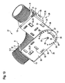
- FIG. 9 shows a perspective view of a first embodiment of a device 27 according to the invention for attaching a flexible tube.
- the device 27 has two fasteners 28 and 29, which substantially in the FIG. 8 Corresponding fastener 1 correspond, wherein like elements are provided with the same reference numerals, so reference is made in this respect to the description of the above figures.
- the fastening elements 28 and 29 each have an extended leg 30, 31, which essentially correspond to the leg 6, and at its free end, so the recesses 9 having legs 5 opposite end, arranged one above the other and are pivotally connected to each other.
- the fastening element 29 lies with its leg 31 in regions on the leg 30 of the fastening element 28.
- the two legs 31 and 30 are connected to each other by means of a rotary joint 32, wherein the rotary joint 32 is formed by one of the legs 30 and 31 interconnecting blind rivets 33.
- Both legs 30, 31 have a plurality of Einstellschraubenötechnisch 34 and 35 which are arranged distributed on an imaginary coaxial circle around the axis of rotation of the rotary joint 32 around.
- the fastening elements 28 and 29 By turning the fastening elements 28 and 29 relative to one another, at least two adjusting screw openings 34, 35 of the legs 30 and 31 can be brought into an overlapping position relative to one another in at least one angular position of the legs 30 and 31, so that an adjusting screw 36 fits into the two adjusting screw openings 34 that are aligned with one another. 35 can be introduced.
- the bottom adjusting screw 35 has a thread into which the adjusting screw 36 can be screwed, so that a secure connection of the legs 30 and 31 and the fasteners 28 and 29 is ensured in a desired angular position to each other.
- the overhead fastener 29 may have a single set screw hole 34.
- the legs 30 and 31 each have at least one slot-like opening 37 for a screw or the like, which differ from the openings 16 in that they extend arcuately on a circle coaxial with the axis of rotation 33, so that they also in at least one angular position the legs 30 and 31 at least partially aligned with each other or overlap.
- the device 27 may be attached to a wall or the like by means of the openings 16 formed in the legs 30, 31.
- the device 27 may be secured to the article 16 with the opening 16 formed in the side legs 18, particularly at the transition from a wall to a ceiling.
- the side legs 18 are arranged on the same side of the device 27, as shown.
- the device 27 allows in a particularly simple manner to set a bending angle of a pipe or corrugated pipe.
- the device 27 is attached to the object, at the desired angle, and then the tube in a simple manner in the two pipe fittings 8 after each other or simultaneously clipped. Due to the advantageous, above-described axial securing, the bend in the pipe, or corrugated pipe, always maintained.
- FIG. 10 shows the back of the device 27 in a perspective view, wherein the corrugated tube is clipped into the pipe fittings 8 fasteners 28 and 29, so that the respective undercut 11, the corrugated tube 3 engages in a shaft space behind.
- the representation of the back side of the device 27 shows the advantageous embodiment of the lower leg 30 with a plurality of Einstellschraubenö réelleen 35, which are substantially uniformly spaced from each other on an (imaginary) circle to the axis of rotation of the pivot joint 32 and thus a versatile adjustment of the device 27 allow.
- a one-piece design of the device 27 at a predetermined angle of the legs 30 and 31 to each other is conceivable. It is also conceivable to provide at the free ends of the legs 30 and 31 means for mating the fastening elements 28 and 29, which allow mating of the fastening elements 28 and 29 in one or more different angles to each other.
- FIG. 11 shows a plan view of the leg 5 of the overhead fastener 29 of the device 27, as shown in the FIG. 11 is shown, wherein the fastening elements 28 and 29 are aligned perpendicular to each other.
- the circular formation of the open-edged recess 9 in the leg 5 can be seen particularly well. Since the center of the circular recess 9 is located within the leg 5, the undercut 11, as already described above, realized, which serves for engaging behind the tube 2 or corrugated tube 3, or the clipping of the corrugated tube 3 in the attachment 8 allowed.
- FIG. 12 perspective view of an advantageous application example of the device 27 is shown.
- FIG. 12 An embodiment of an advantageous conduit system 41, in which two of the devices 27 are connected to each other at the back by means of screw 38 and secured by the side legs 18 on two substantially mutually perpendicular objects, such as a ceiling 39 and a wall 40 of a building.
- the pipe fittings 8 of the devices 27 are two corrugated pipes 3, as above already described, clipped.
- each of the corrugated pipes 3 is secured to the corresponding pipe attachment 8 by means of the loop-shaped holding means 21, which eino in the two-sided notches 12.
- the advantageous device thus also allows the mounting of two parallel corrugated pipes 3 in a simple manner.
- the conduit system 41 may alternatively or additionally also of fasteners 1, as shown in the FIGS. 1 to 8 have been described, formed or supplemented.
- the conduit system 41 is designed for fastening corrugated tubes / pipes with a diameter of 63 mm, 75 mm or 90 mm.
- a production of fasteners made of other materials, such as plastic is possible.
- the desired angle can be adjusted or readjusted before or after clipping in the corrugated tube.
- the device 27 can also be aligned such that the tube is guided straight, so that therefore an angle of 180 ° between the fasteners 28 and 29 is present.
Description
Die Erfindung betrifft ein Befestigungselement, eine Vorrichtung sowie ein Verfahren zum Befestigen eines flexiblen Rohres, insbesondere eines flexiblen Wellrohres, an einem Gegenstand, insbesondere einer Wand, Decke oder dergleichen, mit einer Rohrbefestigung.The invention relates to a fastening element, a device and a method for attaching a flexible tube, in particular a flexible corrugated tube, to an object, in particular a wall, ceiling or the like, with a pipe attachment.
Befestigungselemente, Vorrichtungen und Verfahren der eingangs genannten Art sind dem Fachmann seit Langem bekannt, sieche z.B.
Die bekannten Befestigungselemente haben den Nachteil, dass ein Monteur bei der Montage das Rohr halten, das zweite Blechteil zum Schließen der Rohrschelle umlegen, ausrichten und an dem anderen Blechteil festschrauben muss. Für einen einzelnen Monteur ist dies mitunter mühsam und kompliziert. Darüber hinaus können sich die Rohrschellen an dem Gegenstand beziehungsweise an der Wand leicht verdrehen, da sie mit nur einer einzigen Schraubverbindung an der Wand festgemacht sind, sodass sie leicht um die Achse der Schraubverbindung verdreht werden können. Insbesondere bei einer Richtungsänderung des zu verlegenden Rohres, beispielsweise wenn das Rohr einer bestimmten Kurvenbahn folgend an dem Gegenstand beziehungsweise an der Wand befestigt werden soll, führt dies schnell zu Problemen.The known fasteners have the disadvantage that a fitter hold the pipe during assembly, move the second sheet metal part to close the pipe clamp, align and screwed to the other sheet metal part. For a single mechanic, this is sometimes tedious and complicated. In addition, the pipe clamps can easily twist on the object or on the wall, since they are fixed with only a single screw on the wall, so that they can be easily rotated about the axis of the screw. In particular, when a change in direction of the pipe to be laid, for example, when the pipe is to be attached to a certain curved path following the object or on the wall, this quickly leads to problems.
Der Erfindung liegt somit die Aufgabe zugrunde, ein Befestigungselement, eine Vorrichtung sowie ein Verfahren zum Befestigen eines flexiblen Rohres an einem Gegenstand zu erschaffen, das auf einfache und kostengünstige Art und Weise ein einfaches Befestigen des Rohres erlaubt.The invention is therefore an object of the invention to provide a fastener, an apparatus and a method for attaching a flexible tube to an object, which allows a simple and cost-effective manner easy attachment of the tube.
Diese Aufgabe wird erfindungsgemäß durch die Ausbildung des Befestigungselements als ein mindestens zwei Schenkel aufweisendes Winkelelement gelöst, wobei die Rohrbefestigung als randoffene Ausnehmung mit einem ein Hintergreifen des Durchmessers des Rohres ermöglichenden Hinterschnitt in mindestens einem der Schenkel ausgebildet ist. Zunächst einmal ist also ein Winkelelement vorgesehen, das mindestens zwei Schenkel aufweist. Dies ist einfach und kostengünstig herstellbar. In einem der Schenkel ist dabei eine randoffene Ausnehmung ausgebildet, die als Rohrbefestigung dient. In die randoffene Ausnehmung kann das flexible Rohr radial - im Bezug auf das Rohr - eingebracht werden. Die Ausnehmung weist dabei einen Hinterschnitt auf, der ein Hintergreifen des Durchmessers des Rohres ermöglicht. Unter dem Hinterschnitt ist hierbei eine Ausbildung der Ausnehmung derart zu verstehen, dass die Ausnehmung zweckmäßigerweise im Randbereich eine Verjüngung aufweist, sodass in Montagerichtung gesehen, die Ausnehmung zumindest hinter der Verjüngung breiter ausgebildet ist. Der Hinterschnitt ist dabei derart ausgebildet, dass er ein Hintergreifen des Durchmessers des Rohres ermöglicht, was bedeutet, dass ein in die Ausnehmung eingebrachtes Rohr bereichsweise von dem Hinterschnitt hintergriffen wird. Um das Rohr in die Rohrbefestigung beziehungsweise in die Ausnehmung einzubringen, wird es radial in die Ausnehmung eingebracht, wobei aufgrund des Hinterschnitts der Querschnitt des flexiblen Rohres zunächst elastisch verformt wird, sodass das Rohr durch den durch die Verjüngung verengten Eingangsbereich hindurch gelangt. Nach Passieren des Hinterschnitts beziehungsweise der Verjüngung entspannt sich das flexible Rohr, sodass es seine ursprüngliche Querschnittsform zumindest im Wesentlichen zurück erhält. Mit anderen Worten wird das Rohr in die randoffene Ausnehmung eingeklipst. Aufgrund des vorteilhaften Hinterschnitts kann das Rohr sich nicht ohne Weiteres von der Rohrbefestigung lösen. Dadurch wird das Befestigen des flexiblen Rohres wesentlich vereinfacht. Ein Monteur muss nunmehr lediglich zunächst das Winkelelement mit dem die Ausnehmung nicht aufweisenden Schenkel an dem Gegenstand befestigen und kann anschließend auf einfache Art und Weise das flexible Rohr in die randoffene Ausnehmung einklipsen, sodass der Hinterschnitt das Rohr hintergreift. Das Rohr kann somit mit wenigen Montageschritten einfach und sicher an dem Gegenstand befestigt werden.This object is achieved by the formation of the fastener as an at least two legs exhibiting angle element, wherein the pipe attachment is designed as open-edged recess with a rear engaging the diameter of the pipe enabling undercut in at least one of the legs. First of all, therefore, is an angle element provided, which has at least two legs. This is easy and inexpensive to produce. In one of the legs while an open-edged recess is formed, which serves as a pipe attachment. In the open-edged recess, the flexible tube can be radially - with respect to the pipe - introduced. The recess in this case has an undercut, which allows engaging behind the diameter of the tube. Under the undercut is in this case an embodiment of the recess to be understood such that the recess expediently has a taper in the edge region, so seen in the mounting direction, the recess is formed wider at least behind the taper. The undercut is designed such that it allows engaging behind the diameter of the tube, which means that an introduced into the recess pipe is partially engaged behind by the undercut. In order to introduce the tube into the tube attachment or into the recess, it is introduced radially into the recess, wherein due to the undercut the cross section of the flexible tube is first deformed elastically, so that the tube passes through the narrowed by the tapered input area. After passing through the undercut or the taper, the flexible tube relaxes so that it at least essentially retains its original cross-sectional shape. In other words, the tube is clipped into the open-edged recess. Due to the advantageous undercut, the pipe can not be easily detached from the pipe attachment. As a result, the attachment of the flexible tube is considerably simplified. An installer must now only attach the angle element with the recess not having legs on the object and then can In a simple way, clip the flexible tube into the open-edged recess so that the undercut engages behind the tube. The tube can thus be easily and securely attached to the object with a few assembly steps.
Zweckmäßigerweise ist der die Ausnehmung aufweisende erste Schenkel senkrecht oder im Wesentlichen senkrecht zu dem zweiten Schenkel angeordnet, sodass das Rohr parallel zu dem Gegenstand geführt werden kann und sicher in der Ausnehmung einliegt.Conveniently, the first leg having the recess is arranged perpendicularly or substantially perpendicular to the second leg, so that the tube can be guided parallel to the object and securely seated in the recess.
In der Regel weisen zu verlegende flexible Rohre einen kreisförmigen Querschnitt auf. Vorteilhafterweise ist daher die Ausnehmung im Wesentlichen kreisförmig ausgebildet, sodass die Kontur der Ausnehmung im Wesentlichen der des zu befestigenden Rohres entspricht, wodurch ein sicherer Halt gewährleistet wird. Alternativ ist es bevorzugt denkbar, die Ausnehmung ovalförmig auszubilden, sodass auch Rohre mit einem im Wesentlichen ovalen Querschnitt sicher in der Ausnehmung gehalten werden können. Prinzipiell ist jedoch auch jede andere beliebige Querschnittsform der Ausnehmung denkbar, sofern sie einen Hinterschnitt - wie oben beschreiben - aufweist. So muss auch die Form der Aussparung nicht unbedingt der Querschnittsform des Rohres entsprechen.As a rule, flexible tubes to be laid have a circular cross-section. Advantageously, therefore, the recess is formed substantially circular, so that the contour of the recess substantially corresponds to that of the pipe to be fastened, whereby a secure hold is ensured. Alternatively, it is preferably conceivable to form the recess oval-shaped, so that pipes with a substantially oval cross section can be securely held in the recess. In principle, however, any other arbitrary cross-sectional shape of the recess is also conceivable, provided that it has an undercut as described above. Thus, the shape of the recess does not necessarily correspond to the cross-sectional shape of the tube.
Bevorzugt ist in dem zweiten Schenkel mindestens eine, vorzugsweise mehrere Öffnungen für eine Schraube oder dergleichen ausgebildet. Die Schraube kann dann in den Gegenstand beziehungsweise in die Wand oder in einen in der Wand vorgesehenen Dübel eingeschraubt, und somit das Winkelelement beziehungsweise das Befestigungselement an dem Gegenstand befestigt werden. Sind zwei Öffnungen vorgesehen, kann darüber hinaus auch die Ausrichtung des Befestigungselements an dem Gegenstand genau definiert werden. Ein Verdrehen des Befestigungselements bei der Montage des Rohres ist dann nicht mehr möglich, wodurch insbesondere die Montage eines Rohres entlang einer Krümmung beziehungsweise Kurve vereinfacht wird.Preferably, at least one, preferably a plurality of openings for a screw or the like is formed in the second leg. The screw can then be screwed into the article or into the wall or into a wall provided in the dowel, and thus the angle element or the fastener are attached to the object. If two openings are provided, in addition, the orientation of the fastener to the object are defined precisely. A rotation of the fastener during assembly of the tube is then no longer possible, whereby in particular the assembly of a tube along a curve or curve is simplified.
Nach einer Weiterbildung der Erfindung ist ein dritter Schenkel vorgesehen, der als Seitenschenkel ausgebildet ist und mindestens eine Öffnung für eine Schraube oder dergleichen aufweist. Der dritte Schenkel ist somit seitlich angeordnet und geht bevorzugt entweder von dem ersten, die Rohrbefestigung aufweisenden Schenkel oder aber von dem zweiten Schenkel aus. Bei der Montage des Befestigungselements an dem Gegenstand kann somit die Ausrichtung der Rohrbefestigung beziehungsweise der Ausnehmung je nach Bedarfsfall variiert werden. So kann vorgesehen sein, dass die Ausrichtung der Ausnehmung vertikal oder horizontal ist. So kann beispielsweise das gleiche Befestigungselement sowohl für die Befestigung des Rohres an einer Decke als auch an einer senkrecht dazu verlaufenden beziehungsweise ausgerichteten Wand verwendet werden, wobei das Rohr stets sicher in der randoffenen Ausnehmung gehalten ist.According to a development of the invention, a third leg is provided, which is designed as a side leg and has at least one opening for a screw or the like. The third leg is thus arranged laterally and is preferably either from the first, the pipe attachment having legs or from the second leg. When mounting the fastener on the object thus the orientation of the pipe attachment or the recess can be varied as needed. Thus it can be provided that the orientation of the recess is vertical or horizontal. Thus, for example, the same fastening element can be used both for fastening the pipe to a ceiling and to a wall extending perpendicularly thereto or oriented, the pipe always being held securely in the open-edged recess.
Vorteilhafterweise ist mindestens eine der Öffnungen langlochartig ausgebildet. Bei der Montage des Befestigungselements an dem Gegenstand können zuerst Löcher in die das Befestigungselement haltende Wand gebohrt werden. Häufig sind derartige Löcher jedoch nicht ausreichend genau in die Wand einbringbar, sodass mittels der langlochartig ausgebildeten Öffnung eine Nachjustage des Befestigungselements vorgenommen werden kann. Unter bestimmten Voraussetzungen ist ein derartiges Nachjustieren der Ausrichtung beziehungsweise Anordnung des Befestigungselements an dem Gegenstand auch noch nach Einbringen des flexiblen Rohres in die Rohrbefestigung möglich.Advantageously, at least one of the openings is formed slot-like. When mounting the fastener to the article, holes may first be drilled in the wall holding the fastener. Frequently, however, such holes are not sufficiently accurately introduced into the wall, so that by means of the slot-like opening a readjustment of the fastener can be made. Under certain conditions, such a readjustment of the orientation or Arrangement of the fastener on the object even after insertion of the flexible tube in the pipe attachment possible.
Nach einer Weiterbildung der Erfindung weist das Winkelelement mindestens eine beidseitige Einkerbung, insbesondere im Biegebereich, insbesondere zwischen dem ersten und dem zweiten Schenkel, für ein das Rohr umgreifendes schlauchförmiges Haltemittel auf. Das Winkelelement weist somit zwischen dem ersten und dem zweiten Schenkel beidseitige Einkerbungen auf. Bei der Montage kann ein schlaufenförmiges Haltemittel, wie zum Beispiel ein Draht oder eine Schnur oder auch ein Kabelbinder, um das Rohr und den ersten Schenkel herum geführt werden, wobei es zur Sicherung in die Einkerbungen eingelegt beziehungsweise durch diese hindurchgeführt wird. Die Einkerbungen bieten somit einen sicheren Halt für das das Rohr zusätzlich haltende Haltemittel.According to a development of the invention, the angle element has at least one notch on both sides, in particular in the bending region, in particular between the first and the second leg, for a tube-engaging tubular holding means. The angle element thus has on both sides notches on between the first and the second leg. During assembly, a loop-shaped holding means, such as a wire or a string or a cable tie, are guided around the tube and the first leg, wherein it is inserted for securing in the notches or is passed therethrough. The notches thus provide a secure hold for the tube additionally retaining means.
Zusätzlich oder alternativ ist vorteilhafterweise vorgesehen, dass in dem zweiten Schenkel wenigstens eine Befestigungslasche für ein schlaufenförmiges Haltemittel, insbesondere für einen Kabelbinder oder dergleichen, angeordnet ist. Vorzugsweise ist die Befestigungslasche nahe zu dem ersten Schenkel angeordnet, sodass das schlaufenförmige Haltemittel um das Rohr und den ersten Schenkel herum und in die Befestigungslasche eingehakt werden kann. Hierdurch kann das Rohr auf einfache Art und Weise dauerhaft an dem Befestigungselement sicher arretiert werden.Additionally or alternatively, it is advantageously provided that at least one fastening tab for a loop-shaped holding means, in particular for a cable tie or the like, is arranged in the second leg. Preferably, the fastening tab is disposed close to the first leg so that the loop-shaped retaining means can be hooked around the tube and the first leg and into the fastening tab. As a result, the tube can be securely locked permanently to the fastening element in a simple manner.
Vorteilhafterweise ist die Befestigungslasche als aus dem zweiten Schenkel heraus gebogene Befestigungszunge ausgebildet. Vorzugsweise wird die Befestigungszunge dazu bei der Herstellung des Winkelelements zunächst aus dem vollen Material insbesondere dreiseitig freigeschnitten und dann entsprechend herausgebogen. Zweckmäßigerweise ist das freie Ende der Befestigungszunge von dem ersten Schenkel wegweisend ausgerichtet, sodass das Rohr beziehungsweise das schlaufenförmige Haltemittel sicher daran gehalten werden kann.Advantageously, the fastening strap is formed as a fastening tongue bent out of the second leg. Preferably, the fastening tongue is in the manufacture of the Angle element initially cut out of the full material in particular three sides and then bent out accordingly. The free end of the fastening tongue is expediently oriented in a pioneering manner by the first leg, so that the tube or the loop-shaped retaining means can be securely held thereon.
Nach einer Weiterbildung der Erfindung ist das Material des Winkelelements im Wesentlichen so dick wie ein Wellenzwischenraum des Wellrohres ausgebildet. Mit anderen Worten entspricht die Höhe eines Querschnitts durch das Winkelelement im Wesentlichen dem Raum, der zwischen zwei benachbarten Wellen des Wellrohres ausgebildet ist. Wird nun das Wellrohr derart in das Befestigungselement beziehungsweise in die in dem ersten Schenkel ausgebildete Ausnehmung eingebracht, dass der Hinterschnitt der Ausnehmung den Durchmesser des Wellenzwischenraumes hintergreift, das Winkelelement also zwischen zwei benachbarten Wellen des Wellenrohres liegt, so entsteht zwischen dem Winkelelement und dem Wellrohr eine Axialsicherung. Somit kann das Wellrohr nur radial aus der Ausnehmung herausgenommen werden. Ein Durchziehen des Wellrohres in axialer Richtung wird wirksam durch die mit dem ersten Schenkel zusammenwirkenden Wellen des Wellrohres verhindert. Dies wirkt sich insbesondere vorteilhaft auf die Montage eines einer Kurvenbahn folgenden Wellrohres aus. Entspricht die Dicke des Materials des Winkelelements im Wesentlichen dem Wellenzwischenraum, so kann das Wellrohr auch spielfrei (axial) in der Ausnehmung gehalten werden.According to a development of the invention, the material of the angle element is formed substantially as thick as a shaft gap of the corrugated pipe. In other words, the height of a cross section through the angle element substantially corresponds to the space formed between two adjacent corrugations of the corrugated tube. Now, if the corrugated tube is introduced into the fastening element or into the recess formed in the first leg, that the undercut of the recess engages behind the diameter of the shaft intermediate space, the angle element between two adjacent waves of the shaft tube is formed between the angle element and the corrugated pipe axial locking. Thus, the corrugated tube can only be removed radially from the recess. Pulling through the corrugated pipe in the axial direction is effectively prevented by the cooperating with the first leg waves of the corrugated pipe. This has a particularly advantageous effect on the assembly of a corrugated tube following a curved path. Corresponds to the thickness of the material of the angle element substantially the shaft space, the corrugated tube can also be held without play (axially) in the recess.
Nach einer vorteilhaften Weiterbildung der Erfindung ist an einem dem ersten Schenkel gegenüberliegenden Ende des zweiten Schenkels ein weiterer beziehungsweise vierter Schenkel vorgesehen, der dem ersten Schenkel entspricht, also ebenfalls die erfindungsgemäße Rohrbefestigung aufweist. Vorteilhafterweise ist das Winkelelement dabei im Wesentlichen U-förmig ausgebildet, sodass der erste und der vierte Schenkel miteinander fluchten, wodurch eine doppelte Rohrbefestigung an dem einen Befestigungselement geboten wird. Der dritte Schenkel ist optional.According to an advantageous embodiment of the invention is at an opposite end of the first leg of the second leg a further or fourth leg provided, which corresponds to the first leg, so also having the pipe attachment according to the invention. Advantageously, the angle element is formed substantially U-shaped, so that the first and the fourth leg are aligned with each other, whereby a double pipe attachment to the one fastener is offered. The third leg is optional.
Bevorzugt ist der zweite Schenkel zumindest bereichsweise derart gebogen, dass der erste und der vierte Schenkel in einem Winkel, insbesondere senkrecht zueinander ausgerichtet sind. Der zweite beziehungsweise mittlere Schenkel ist somit um einen bestimmen Winkel gebogen, besonders bevorzugt weist er eine Biegekante auf. Typischerweise sind die Schenkel eines Winkelelements selbst eben ausgebildet und weisen nur an ihrem dem benachbarten Schenkel zugeordneten Ende eine entsprechende Biegekante auf. Ist nun der zweite Schenkel wie oben beschrieben gebogen, so kann das Befestigungselement als Winkel-Befestigungselement beziehungsweise Kurvenbefestigungselement verwendet werden. Durch die vorgegebene Ausrichtung der beiden die Rohrbefestigung aufweisenden Schenkel (erster und dritter Schenkel) wird dem Rohr beziehungsweise dem Wellrohr ein bestimmter Winkel beziehungsweise Radius vorgegeben. Ein derartiges Winkel-Befestigungselement kann beispielsweise beim Übergang von einer Decke zu einer senkrecht dazu verlaufenden Wand verwendet werden.Preferably, the second leg is at least partially bent such that the first and the fourth leg are aligned at an angle, in particular perpendicular to each other. The second or middle leg is thus bent by a certain angle, more preferably it has a bending edge. Typically, the legs of an angle element are themselves flat and have a corresponding bending edge only at their end associated with the adjacent leg. Now, if the second leg is bent as described above, then the fastener can be used as an angle fastener or curve fastener. Due to the predetermined orientation of the two legs having the pipe attachment (first and third leg) the tube or the corrugated pipe is given a certain angle or radius. Such an angle fastening element can be used, for example, in the transition from a ceiling to a wall extending perpendicular thereto.
Mit Vorteil ist vorgesehen, dass das Winkelelement als Winkelblech ausgebildet ist. Somit ist eine stabile und belastbare Rohrbefestigung möglich.It is advantageously provided that the angle element is designed as an angle plate. Thus, a stable and reliable pipe mounting is possible.
Insbesondere kann das Befestigungselement als Stanz-Biege-Teil ausgebildet sein. Dazu wird das Winkelelement beziehungsweise das Winkelblech zunächst aus einem ebenen Blechteil herausgeschnitten oder gestanzt und anschließend werden die Schenkel in die gewünschte Ausrichtung beziehungsweise das Winkelelement in die gewünschte Form gebogen. Dies kann besonders vorteilhaft in einem einzigen Bearbeitungsschritt geschehen, sodass das Befestigungselement besonders einfach und kostengünstig herstellbar ist.In particular, the fastening element may be formed as a stamped and bent part. For this purpose, the angle element or the angle plate is first cut or punched from a flat sheet metal part and then the legs are bent into the desired orientation or the angle element in the desired shape. This can be done particularly advantageously in a single processing step, so that the fastener is particularly easy and inexpensive to produce.
Die erfindungsgemäße Vorrichtung kennzeichnet sich durch mindestens zwei Befestigungselemente aus, die wie oben beschrieben ausgebildet sind, und mittels eines Drehgelenks drehgelenkig miteinander verbunden sind. Bei der Befestigung von Rohren, insbesondere von Wellrohren, steht man häufig vor dem Problem, dass das Rohr um Ecken und Winkel gelegt beziehungsweise geführt werden muss, die keiner Norm entsprechen und somit beispielsweise das oben beschriebene Befestigungselement mit dem ersten, dem zweiten und dem vierten Schenkel nicht verwendbar wäre. Die erfindungsgemäße Vorrichtung bietet somit mittels des Drehgelenks drehgelenkig miteinander verbundene Befestigungselemente, wobei der Winkel entweder voreingestellt oder durch den Monteur vor Ort einstellbar ist. Das Drehgelenk erlaubt das einfache Anpassen und insbesondere gegebenenfalls ein stufenloses Anpassen der Ausrichtung der Befestigungselemente zueinander, sodass die Vorrichtung an jeden Bedarfsfall anpassbar ist.The device according to the invention is characterized by at least two fastening elements, which are formed as described above, and are pivotally connected to each other by means of a rotary joint. In the attachment of pipes, in particular of corrugated pipes, it is often the problem that the pipe must be placed or guided around corners and angles that do not correspond to a standard and thus, for example, the above-described fastener with the first, the second and the fourth Thighs would not be usable. The device according to the invention thus provides by means of the rotary joint pivotally interconnected fasteners, wherein the angle is either preset or adjustable by the fitter on site. The hinge allows easy adjustment and, in particular, optionally a continuous adjustment of the orientation of the fasteners to each other, so that the device is adaptable to any need.
Zweckmäßigerweise ist das Drehgelenk an einem dem jeweiligen ersten Schenkel gegenüberliegenden Endes des zweiten Schenkels angeordnet. In diesem Fall weisen die Befestigungselemente zweckmäßigerweise jeweils nur einen die erfindungsgemäße Rohrbefestigung aufweisenden (ersten) Schenkel auf, sodass die Befestigungselemente selbst im Wesentlichen L-förmig ausgebildet sind. An dem zu der Rohrbefestigung fernen Ende des jeweiligen Befestigungs- beziehungsweise Winkelelements ist das Drehgelenk vorgesehen. Je nach Ausbildung des Drehgelenks können die Befestigungselemente scherenartig zueinander verschränkt beziehungsweise verdreht werden, sodass die Befestigungselemente in einer Ebene zueinander verlagerbar sind, oder entlang einer Kante derart zueinander geklappt werden, dass beispielsweise die Vorrichtung eine W-Form (mit im Wesentlichen rechten Winkeln) erhält.Conveniently, the hinge is arranged on an opposite end of the respective first leg of the second leg. In this case, the fastening elements expediently each have only one (first) leg having the pipe fastening according to the invention, so that the fastening elements themselves are essentially L-shaped. At the remote to the pipe attachment end of the respective fastening or angular element, the rotary joint is provided. Depending on the design of the rotary joint, the fastening elements can be scissored-like interlocked or twisted, so that the fastening elements are displaceable in a plane to each other, or folded along an edge to each other, for example, that the device receives a W-shape (with substantially right angles) ,
Bevorzugt wird das Drehgelenk von einer die aufeinanderliegenden zweiten Schenkel miteinander verbindenden Blindniete gebildet. Es ist also vorgesehen, dass zunächst die beiden zweiten Schenkel der beiden Befestigungselemente aufeinander aufliegen. Die die beiden zweiten Schenkel miteinander verbindende Blindniete bildet daher eine besonders einfache und kostengünstige Möglichkeit eine Winkeleinstellung zwischen den beiden Befestigungselementen zu gewährleisten. Die Blindniete definiert dabei eine Drehachse, um die die Befestigungselemente geschwenkt werden können.Preferably, the rotary joint is formed by one of the superimposed second leg interconnecting blind rivets. It is thus provided that initially the two second legs of the two fastening elements rest on one another. The blind rivets interconnecting the two second legs therefore forms a particularly simple and cost-effective way of ensuring an angular adjustment between the two fastening elements. The blind rivets defines an axis of rotation about which the fasteners can be pivoted.
Nach einer vorteilhaften Weiterbildung der Erfindung weist jeder der zweiten Schenkel mindestens eine Einstellschraubenöffnung auf einem koaxial zu der Drehachse des Drehgelenks beziehungsweise der Blindniete ausgerichteten - gedachten - Kreis auf. Die Einstellschraubenöffnung des jeweiligen Schenkels befindet sich also auf einem (gedachten) Kreis um die Drehachse des Drehgelenks, sodass wenn die Befestigungselemente zueinander verdreht beziehungsweise verschwenkt werden die Einstellschraubenöffnungen der beiden Schenkel in einer bestimmten Position der Schenkel zueinander miteinander fluchten.According to an advantageous embodiment of the invention, each of the second leg at least one Einstellschraubenöffnung on a coaxial with the axis of rotation of the rotary joint or the blind rivets aligned - imaginary - circle. The Einstellschraubenöffnung of the respective leg is thus on an (imaginary) circle around the axis of rotation of the rotary joint, so that when the fasteners are rotated or pivoted to each other, the Einstellschraubenöffnungen the two legs in a certain position of the legs are aligned with each other.
Weist nun vorteilhafterweise wenigstens einer der Schenkel mehrere auf dem Radius verteilt angeordnete Einstellschraubenöffnungen auf, so kann die Vorrichtung in einer bestimmten Winkelposition der Befestigungselemente zueinander durch Einfügen einer Einstellschraube oder eines Einstellstifts arretiert werden. Zweckmäßigerweise sind in der oder den Einstellschraubenöffnungen eines der Schenkel Gewinde ausgebildet, in die die Einstellschraube eingeschraubt werden kann. Je nach Anzahl und Winkelabstand zueinander sind dabei unterschiedlich viele und unterschiedlich große Einstellwinkel zwischen den Befestigungselementen festlegbar beziehungsweise Einstellbar.If advantageously at least one of the legs has a plurality of adjusting screw openings arranged distributed on the radius, then the device can be locked to one another in a certain angular position of the fastening elements by inserting an adjusting screw or a setting pin. Conveniently, in the one or more Einstellschraubenöffnungen one of the legs threaded, into which the adjusting screw can be screwed. Depending on the number and angular distance from one another, different numbers of differently sized setting angles between the fastening elements can be fixed or adjusted.
Besonders bevorzugt weist der oben liegende zweite Schenkel zwei Einstellschraubenöffnungen und der unten liegende zweite Schenkel mindestens zwei Einstellschraubenöffnungen auf. Zweckmäßigerweise weist der unten liegende zweite Schenkel eine Vielzahl von Einstellschraubenöffnungen auf. Zweckmäßigerweise sind vorzugsweise dabei die Einstellschraubenöffnungen beider zweiter Schenkel gleich beabstandet jeweils über zumindest einen Winkelbereich auf dem Kreis angeordnet. Das bedeutet, dass die Einstellschraubenöffnungen eines zweiten Schenkels den gleichen Abstand beziehungsweise Winkelabstand zueinander aufweisen. Wird nun bei dem oben liegenden Schenkel eine Einstellschraube in eine der beiden Einstellschraubenöffnungen eingebracht, dient die zweite in dem oben liegenden zweiten Schenkel ausgebildete Einstellschraubenöffnungen als optische Hilfe beim Einstellen des Winkels zwischen den beiden Befestigungselementen. Aufgrund des gleichen Abstandes der Einstellschraubenöffnungen zueinander kann davon ausgegangen werden, dass wenn durch die als optische Hilfe dienende zweite Einstellschraubenöffnung eine darunter liegende Einstellschraubenöffnung fluchtet, auch eine weitere Einstellschraubenöffnung des darunter liegenden zweiten Schenkels mit der Einstellschraubenöffnung fluchtet in der die Einstellschraube einliegt. Dadurch wird die Montage für den Monteur erleichtert und Fehler werden vermieden. Weiterhin ist es denkbar, zumindest eine der Einstellschraubenöffnungen in dem oben liegenden zweiten Schenkel als Langloch auszubilden, sodass eine stufenlose Winkeleinstellung zwischen dem Befestigungselement möglich ist.Particularly preferably, the upper second leg has two Einstellschraubenöffnungen and the underlying second leg at least two Einstellschraubenöffnungen. Conveniently, the lower second leg has a plurality of Einstellschraubenöffnungen. Conveniently, the Einstellschraubenöffnungen both second legs are preferably equally spaced in each case over at least one angular range arranged on the circle. This means that the Einstellschraubenöffnungen a second leg have the same distance or angular distance from each other. If now an adjusting screw is inserted into one of the two Einstellschraubenöffnungen in the upper leg, the second serves in the above Adjusting screw openings formed as the second leg lying as an optical aid in adjusting the angle between the two fasteners. Due to the same distance of the Einstellschraubenöffnungen each other can be assumed that when the serving as a visual aid second Einstellschraubenöffnung an underlying Einstellschraubenöffnung is aligned, also another Einstellschraubenöffnung the underlying second leg with the Einstellschraubenöffnung aligned in the rests the adjusting screw. As a result, the installation is easier for the fitter and mistakes are avoided. Furthermore, it is conceivable to form at least one of the Einstellschraubenöffnungen in the upper lying second leg as a slot, so that a continuous angle adjustment between the fastener is possible.
Zweckmäßigerweise sind die dritten Schenkel der Befestigungselemente, sofern sie vorgesehen sind, auf derselben Seite der Vorrichtung angeordnet. Dadurch kann die Vorrichtung beispielsweise derart an einer Ecke einer Wand angeordnet werden, dass sie mittels der Seitenschenkel an der Wand befestigbar ist und ein Rohr in die Rohrbefestigung von oben einbringbar ist. Hierbei ergeben sich natürlich noch weitere Möglichkeiten, auf die jedoch später näher eingegangen werden soll.Conveniently, the third legs of the fasteners, if provided, are arranged on the same side of the device. As a result, the device can for example be arranged on a corner of a wall in such a way that it can be fastened to the wall by means of the side limbs and a tube can be introduced into the tube fastening from above. Of course, there are other possibilities, which will be discussed in more detail later.
Das erfindungsgemäße Leitungssystem für flüssige und/oder gasförmige Stoffe, durch das natürlich beispielsweise auch Kabel geführt werden können, ist dadurch gekennzeichnet, dass das Befestigungselement und/oder die Vorrichtung zum Befestigen eines flexiblen Rohres wie oben beschrieben ausgebildet sind. Dem Fachmann erlaubt dies eine besonders einfache und schnelle Montage des flexiblen Rohres auch an schwierigen Stellen, wie zum Beispiel dem Übergang von einer Wand zu einer Dachschräge.The conduit system according to the invention for liquid and / or gaseous substances, by the course, of course, cables can be performed, is characterized in that the fastening element and / or the device for fixing a flexible tube are formed as described above. This allows a person skilled in the art a particularly simple and quick installation of the flexible Pipe also in difficult places, such as the transition from a wall to a sloping roof.
Bevorzugt ist das Rohr als Wellrohr ausgebildet. Vorzugsweise entspricht die Kontur der Ausnehmung des Befestigungselements im Wesentlichen dem Querschnitt des Wellrohres in einem Wellenzwischenraum. Dadurch liegt das Wellrohr im in die Ausnehmung eingebrachten und damit entspannten Zustand an der Innenseite der Ausnehmung flächig an, wodurch beispielsweise Klappergeräusche oder Ähnliches verhindert werden. Darüber hinaus ist ein sicherer Halt des Wellrohres in der Rohrbefestigung gewährleistet.Preferably, the tube is formed as a corrugated tube. Preferably, the contour of the recess of the fastening element substantially corresponds to the cross section of the corrugated pipe in a shaft intermediate space. As a result, the corrugated tube is in the introduced into the recess and thus relaxed state on the inside of the recess surface, whereby, for example, rattling noises or the like can be prevented. In addition, a secure hold of the corrugated pipe is guaranteed in the pipe attachment.
Vorteilhafterweise ist der Querschnitt des Wellrohres im Wesentlichen kreisringförmig oder ovalringförmig ausgebildet. Entsprechend wird die Kontur der Ausnehmung wie oben beschrieben gewählt. Zweckmäßigerweise ist der Durchmesser der Ausnehmung nur geringfügig größer als der des Wellenzwischenraums, sodass einerseits ein sicherer Halt gewährleistet wird und andererseits die Materialien des Wellrohres und/oder des Befestigungs- beziehungsweise Winkelelements nicht dauerhaft belastet werden. Alternativ können (Well-)Rohr und/oder Rohrbefestigung zur Erzeugung einer Presspassung ausgebildet sein.Advantageously, the cross section of the corrugated tube is formed substantially annular or oval ring-shaped. Accordingly, the contour of the recess is selected as described above. Conveniently, the diameter of the recess is only slightly larger than that of the shaft gap, so on the one hand, a secure fit is ensured and on the other hand, the materials of the corrugated pipe and / or the attachment or angle element are not permanently loaded. Alternatively, (corrugated) pipe and / or pipe attachment can be designed to produce a press fit.
Bevorzugt entspricht die Dicke des Materials des Winkelelements im Wesentlichen der Breite eines Wellenzwischenraums des Wellrohres. Dies führt zu den oben bereits beschriebenen Vorteilen.Preferably, the thickness of the material of the angle element substantially corresponds to the width of a shaft gap of the corrugated pipe. This leads to the advantages already described above.
Schließlich ist vorzugsweise vorgesehen, dass mindestens ein schlaufenförmiges Haltemittel, insbesondere ein Kabelbinder, Draht oder dergleichen vorgesehen ist, das das Rohr umgreift und mit den Einkerbungen und/oder mit der Befestigungslasche zusammenwirkt. Das Haltemittel kann als zusätzliches Sicherungselement angebracht werden, um beispielsweise bei besonders schweren Rohren oder schwer belasteten Rohren ein Lösen von der Vorrichtung beziehungsweise von dem Befestigungselement zu verhindern.Finally, it is preferably provided that at least one loop-shaped holding means, in particular a cable tie, wire or the like is provided, which engages around the tube and cooperates with the notches and / or with the fastening tab. The holding means can be attached as an additional securing element in order to prevent detachment from the device or from the fastening element, for example, in the case of particularly heavy pipes or heavily loaded pipes.
Das erfindungsgemäße Verfahren sieht vor, dass das Rohr im Wesentlichen radial in die Ausnehmung unter elastischer Verformung des Rohrquerschnitts eingebracht wird, sodass sich das vollständig in die Ausnehmung eingebrachte Rohr aufgrund seiner Eigenelastizität in seine Ausgangsform zurückverformt und dadurch der Hinterschnitt der Ausnehmung den Durchmesser des Rohres hintergreift. Mit anderen Worten ist vorgesehen, dass das Rohr in die Ausnehmung eingeklipst wird.The inventive method provides that the tube is introduced substantially radially into the recess with elastic deformation of the tube cross-section, so that the completely inserted into the recess tube deformed back into its original shape due to its inherent elasticity and thereby the undercut of the recess engages behind the diameter of the tube , In other words, it is provided that the tube is clipped into the recess.
Im Folgenden soll die Erfindung anhand mehrerer Ausführungsbeispiele nach den
- Figuren 1
bis 3 - ein erstes nicht erfindungsgemäßes Ausführungsbeispiel eines vorteilhaften Befestigungselements,
- Figur 4
- ein zweites nicht erfindungsgemäßes Ausführungsbeispiel des Befestigungselements,
Figur 5- ein drittes nicht erfindungsgemäßes Ausführungsbeispiel des Befestigungselements für ein ovales Rohr,
Figur 6- ein viertes nicht erfindungsgemäßes Ausführungsbeispiel des Befestigungselements für ein ovales Rohr,
- Figur 7
- eine erste nicht erfindungsgemäße zusätzliche Befestigungsmöglichkeit,
Figur 8- eine zweite nicht erfindungsgemäße zusätzliche Befestigungsmöglichkeit,
Figur 9- ein erstes Ausführungsbeispiel einer erfindungsgemäßen Vorrichtung zum Befestigen eines Rohres,
Figur 10- eine Rückenansicht der erfindungsgemäßen Vorrichtung,
Figur 11- eine Seitenansicht der Vorrichtung und
Figur 12- ein Ausführungsbeispiel eines erfindungsgemäßen Leitungssystems.
- FIGS. 1 to 3
- a first non-inventive embodiment of an advantageous fastener,
- FIG. 4
- a second non-inventive embodiment of the fastener,
- FIG. 5
- a third non-inventive embodiment of the fastener for an oval tube,
- FIG. 6
- A fourth non-inventive embodiment of the fastener for an oval tube,
- FIG. 7
- a first non-inventive additional attachment option,
- FIG. 8
- a second non-inventive additional mounting option,
- FIG. 9
- A first embodiment of a device according to the invention for fastening a pipe,
- FIG. 10
- a back view of the device according to the invention,
- FIG. 11
- a side view of the device and
- FIG. 12
- an embodiment of a conduit system according to the invention.
Die
Das Befestigungselement 1 ist als ein Winkelelement 4 ausgebildet, welches zwei Schenkel 5, 6 aufweist, die im Wesentlichen senkrecht zueinander angeordnet sind. Die Schenkel 5, 6 selbst sind dabei eben ausgebildet. Zweckmäßigerweise ist das Winkelelement als ein Winkelblech 7 ausgebildet, sodass der Winkel zwischen den beiden Schenkeln 5 und 6 auf einfache Art und Weise mittels Biegen beziehungsweise Umformen erstellbar ist.The fastening element 1 is formed as an angle element 4, which has two
Das Befestigungselement 1 weist weiterhin eine Rohrbefestigung 8 auf, die zum Befestigen des Rohres 2 an dem Befestigungselement 1 dient. Vorteilhafterweise ist die Rohrbefestigung 8 als eine randoffene Ausnehmung 9 in dem ersten Schenkel 5 ausgebildet. Die Ausnehmung 9 ist zu einem Rand des Winkelelements 4 beziehungsweise des Schenkels 5 hin offen ausgebildet. Weiterhin ist die Ausnehmung 9 in Richtung der Längserstreckung des Winkelelements 4 ausgerichtet. In dem vorliegenden Ausführungsbeispiel weist die Ausnehmung 9 eine im Wesentlichen kreisförmige Kontur auf, wobei der Mittelpunkt des Kreises innerhalb des ersten Schenkels 5 liegt, sodass sich die Ausnehmung 9 zu dem Rand 10 des Schenkels 5, zu dem die Ausnehmung 9 offen ausgebildet ist, verjüngt und einen Hinterschnitt 11 bildet. Weiterhin weist das Befestigungselement 1 beziehungsweise das Winkelelement 4 im Biegebereich zwischen den beiden Schenkeln 5 und 6 eine beidseitige Einkerbung 12 auf, auf die später näher eingegangen werden soll.The fastening element 1 furthermore has a
Das flexible Wellrohr 3, das hier geschnitten dargestellt ist, weist einen wellenförmigen Längsschnitt auf, wobei sich die "Wellen" 13 in dem vorliegenden Ausführungsbeispiel ringförmig jeweils einmal über den gesamten Umfang des Rohres 2 erstrecken und gleichmäßig beabstandet zueinander über das Rohr 2 verteilt angeordnet sind. Alternativ können die Wellen 13 des Wellrohres 3 auch schräg angeordnet oder sogar schrauben- beziehungsweise gewindeförmig ausgebildet sein. Zwischen zwei benachbarten Wellen 13 ist jeweils ein Wellenzwischenraum 14 gebildet, dessen Außendurchmesser kleiner als der der Wellen 13 ist. Vorteilhafterweise entspricht der Durchmesser D1 der randoffenen Ausnehmung 9 im Wesentlichen dem Durchmesser des Wellrohres 3 in einem Wellenzwischenraum 14.The flexible
Im Folgenden soll nun das Befestigen des Wellrohres 3 an dem vorteilhaften Befestigungselement 1 anhand der
Wird das Wellrohr 3 jedoch wie in der
Wird das Wellrohr 3 vollständig in die Ausnehmung 9 in Richtung des Pfeils 15 eingebracht, so nimmt das Wellrohr 3 aufgrund seiner Eigenelastizität seine Ursprungs-(Querschnitts-)Form ein und liegt, wie in der
Im Vergleich zu den ansonsten verwendeten Rohrschellen, wird dadurch die Montage des Wellrohres 3 erheblich vereinfacht, da der Monteur das Wellrohr 3 lediglich in die Ausnehmung 9 einklipsen muss. Ein umständliches Hinzufügen eines zweiten Befestigungselements bei gleichzeitigem Halten des Wellrohres 3 entfällt. Darüber hinaus wird durch die vorteilhafte Ausbildung des Befestigungselements 1 eine Axialsicherung gewährleistet: Da der erste Schenkel 5 zwischen zwei benachbarten Wellen 13 des Wellrohres 3 einliegt, kann letzteres nicht axial in der Ausnehmung 9 verlagert werden.Compared to the otherwise used pipe clamps, thereby the assembly of the
Die
Vorteilhafterweise sind in dem zweiten Schenkel 6 mehrere Öffnungen 16 ausgebildet, im vorliegenden Fall drei Öffnungen 16, durch die zur Befestigung des Befestigungselements 1 an einem Gegenstand, wie zum Beispiel an einer Wand, einer Decke oder dergleichen, eine Schraube, ein Nagel oder Ähnliches durchführbar ist. In dem vorliegenden Ausführungsbeispiel sind die Öffnungen 16 vorteilhafterweise langlochartig ausgebildet, sodass eine Nachjustierung des Befestigungselements 1 durchgeführt werden kann.Advantageously, a plurality of
Weiterhin weist das Winkelelement 4 beziehungsweise das Winkelblech 7 einen dritten Schenkel 17 auf, der als Seitenschenkel 18 ausgebildet und an dem zweiten Schenkel 6 angeordnet ist. Wobei der Seitenschenkel 18 dabei im Wesentlichen senkrecht zu dem ersten Schenkel 5 sowie zu dem zweiten Schenkel 6 ausgerichtet ist. Vorteilhafterweise sind auch in dem Seitenschenkel 18 zwei Öffnungen 16 langlochartig ausgebildet.Furthermore, the angle element 4 or the angle plate 7 on a third leg 17 which is formed as a side legs 18 and disposed on the
So kann bei der Verwendung des vorteilhaften Befestigungselements 1 gemäß dem Ausführungsbeispiel der
Natürlich kann der Seitenschenkel 18 auch auf der gegenüberliegenden Seite des zweiten Schenkels 6 angeordnet sein. Ebenso ist es denkbar, dass der Seitenschenkel 18 nicht auf der gleichen Seite des zweiten Schenkels 6 sondern auf der dem ersten Schenkel 5 gegenüberliegenden Seite des zweiten Schenkels 6, also um 180° gedreht beziehungsweise nach unten gebogen, angeordnet beziehungsweise ausgerichtet ist.Of course, the side leg 18 may also be arranged on the opposite side of the
Natürlich ist die Erfindung nicht auf die Befestigung von - im Querschnitt gesehen - kreisförmigen Rohren beschränkt. Vielmehr können beispielsweise auch elliptische oder ovale Rohre mittels des Befestigungselements 1 befestigt werden. Die
Das ovalförmige Wellrohr 3 kann ebenfalls wie oben beschrieben seitwärts beziehungsweise radial in die randoffene Ausnehmung 9 eingebracht beziehungsweise unter elastischer Verformung eingeklipst werden. Es ist ersichtlich, dass dieses Prinzip für jegliche Querschnittsformen von Wellrohren beziehungsweise Rohren und Ausnehmungen möglich ist. Voraussetzung ist jeweils dass das Wellrohr von einem Hinterschnitt der Ausnehmung hintergriffen wird.The oval-shaped
Die
Die
Die
Die unterschiedlichen Ausführungsformen des Befestigungselements 1 gemäß den vorangehenden
Die
Die Befestigungselemente 28 und 29 weisen jeweils einen verlängerten Schenkel 30, 31 auf, die im Wesentlichen dem Schenkel 6 entsprechen, und die an ihrem freien Ende, also dem die Ausnehmungen 9 aufweisenden Schenkel 5 gegenüberliegenden Ende, übereinander liegend angeordnet und drehgelenkig miteinander verbunden sind. Dabei liegt das Befestigungselement 29 mit seinem Schenkel 31 bereichsweise auf dem Schenkel 30 des Befestigungselements 28 auf. Die beiden Schenkel 31 und 30 sind dabei mittels eines Drehgelenks 32 miteinander verbunden, wobei das Drehgelenk 32 von einer die Schenkel 30 und 31 miteinander verbindenden Blindniete 33 gebildet wird. Beide Schenkel 30, 31 weisen mehrere Einstellschraubenöffnungen 34 beziehungsweise 35 auf, die auf einem gedachten koaxialen Kreis um die Drehachse des Drehgelenks 32 herum verteilt angeordnet sind. Durch Verdrehen der Befestigungselemente 28 und 29 zueinander, können somit zumindest zwei Einstellschraubenöffnungen 34, 35 der Schenkel 30 und 31 in zumindest einer Winkelstellung der Schenkel 30 und 31 zueinander in eine Überlappungsposition gebracht werden, sodass eine Einstellschraube 36 in die zwei miteinander fluchtenden Einstellschraubenöffnungen 34, 35 eingebracht werden kann. Vorteilhafterweise weist dabei die unten liegende Einstellschraubenöffnung 35 ein Gewinde auf, in das die Einstellschraube 36 eingeschraubt werden kann, sodass eine sichere Verbindung der Schenkel 30 und 31 beziehungsweise der Befestigungselemente 28 und 29 in einer gewünschten Winkelposition zueinander gewährleistet ist. Das oben liegende Befestigungselement 29 kann eine einzige Einstellschraubenöffnung 34 aufweisen. Dies würde prinzipiell ausreichen, sofern das unten liegende Befestigungselement 28 mehrere auf dem Radius verteilt angeordnete Einstellschraubenöffnungen 34 aufweisen würde. Vorteilhafterweise weist jedoch das oben liegende Befestigungselement 29 in seinem Schenkel 31, wie dargestellt, zwei Einstellschraubenöffnungen 34 auf, wobei in einer von ihnen die Einstellschraube 36 eingebracht ist. Die Einstellschraubenöffnungen 34, 35 weisen jeweils den gleichen Abstand zu einer benachbarten Einstellschraubenöffnung 34 auf, sind also gleichmäßig verteilt angeordnet. Dadurch wird erreicht, dass wenn die beiden Schenkel 31 und 30 übereinander liegen, die zweite Einstellschraubenöffnung 34 des oben liegenden Schenkels 31 als Justierhilfe verwendet werden kann. Ist nämlich mittels der zweiten Einstellschraubenöffnung 34 zu erkennen, dass diese fluchtend zu einer darunter liegenden Einstellschraubenöffnung 35 des Schenkels 30 liegt, so kann davon ausgegangen werden, dass auch die dazu benachbarte Einstellschraubenöffnung 34, in der die Einstellschraube 36 bereits einliegt, fluchtend zu einer darunter liegenden Einstellschraubenöffnung 35 des Schenkels 30 ausgerichtet ist und somit ein Festziehen der Schraube 25 möglich ist. In dem in der
Weiterhin weisen die Schenkel 30 und 31 jeweils mindestens eine langlochartig ausgebildete Öffnung 37 für eine Schraube oder dergleichen auf, die sich zu den Öffnungen 16 dahingehend unterscheiden, dass sie bogenförmig auf einem Kreis koaxial zu der Drehachse 33 verlaufen, sodass auch sie in zumindest einer Winkelstellung der Schenkel 30 und 31 zueinander zumindest bereichsweise miteinander fluchten beziehungsweise sich überschneiden.Furthermore, the
Bevorzugt weisen die Schenkel 30 und 31 an ihren freien Enden, wie dargestellt, eine halbkreisförmige Rundung auf, die es erlaubt, die Vorrichtung 27 bei jeder Winkelstellung der Befestigungselemente 28 und 29 zueinander in einer Ecke des Gegenstandes (Wand oder dergleichen) zu befestigen. So kann die Vorrichtung 27 beispielsweise mittels den in den Schenkeln 30, 31 ausgebildeten Öffnungen 16 an einer Wand oder dergleichen befestigt werden. Alternativ kann die Vorrichtung 27 mit den in den Seitenschenkeln 18 ausgebildeten Öffnung 16 an dem Gegenstand, insbesondere beim Übergang von einer Wand zu einer Decke, befestigt werden. Vorteilhafterweise sind dazu die Seitenschenkel 18 auf der gleichen Seite der Vorrichtung 27 angeordnet, wie dargestellt.Preferably, the
Die Vorrichtung 27 erlaubt auf besonders einfache Art und Weise das Einstellen eines Biegewinkels eines Rohres beziehungsweise Wellrohres. Dabei wird zunächst die Vorrichtung 27 an dem Gegenstand angebracht, in dem gewünschten Winkel, und anschließend das Rohr auf einfache Art und Weise in die beiden Rohrbefestigungen 8 nach einander oder gleichzeitig eingeklipst. Aufgrund der vorteilhaften, oben beschriebenen Axialsicherung, bleibt die Biegung in dem Rohr, beziehungsweise Wellrohr, stets erhalten.The
Die
Die
In der
Das Leitungssystem 41 kann alternativ oder zusätzlich ebenso von Befestigungselementen 1, wie sie in den
Vorteilhafterweise ist das Leitungssystem 41 zur Befestigung von Wellrohren/Rohren mit einem Durchmesser von 63 mm, 75 mm oder 90 mm ausgebildet. Alternativ zur Ausbildung als Biege-Stanz-Teil beziehungsweise Blech-Stanz-Teil ist natürlich auch eine Fertigung der Befestigungselemente aus anderen Materialien, wie zum Beispiel aus Kunststoff möglich. Bei Verwendung der Vorrichtung 27 kann der gewünschte Winkel vor oder auch nach Einklipsen des Wellrohres eingestellt oder nachjustiert werden. Natürlich kann die Vorrichtung 27 auch derart ausgerichtet werden, dass das Rohr gerade geführt wird, sodass also ein Winkel von 180° zwischen den Befestigungselementen 28 und 29 vorliegt.Advantageously, the conduit system 41 is designed for fastening corrugated tubes / pipes with a diameter of 63 mm, 75 mm or 90 mm. As an alternative to the design as a bending-stamping part or sheet-metal stamping-part of course, a production of fasteners made of other materials, such as plastic is possible. When using the
Claims (15)
- A device for mounting a flexible pipe (2), more particularly a corrugated pipe, to an object, more particularly a wall, a ceiling or the like, having at least two mounting elements (28, 29), wherein, to mount the pipe (2), each mounting element (28, 29) is designed as an angle bracket element (4) that includes at least one first leg and one second leg (5, 6, 17, 30, 31) and includes a pipe mounting piece (8), wherein the pipe mounting piece (8) is designed as an edge-open recess (9) with an undercut (11) in the first leg (5), wherein said undercut (11) allows engaging behind the diameter of the pipe (2), and wherein the first leg (5) is formed flat and is arranged perpendicularly or essentially perpendicularly in relation to the second leg (6, 30, 31) which is likewise formed flat, characterized in that the at least two mounting elements (28, 29) are connected to each other in a pivoting manner by means of a swivel joint (32).
- Device according to claim 1, characterized by a third leg (17) that is designed as a lateral leg (18) and includes at least one hole (16) for a screw or the like.
- Device according to any one of the preceding claims, characterized in that the angle bracket element (4) includes at least one indentation (12) on either side, more particularly in the bending region between the first and the second legs (5, 6, 30) for a loop-shaped holding means (21) encompassing the pipe (2).
- Device according to any one of the preceding claims, characterized in that at least one mounting strap (21) for a loop-shaped holding means (25), more particularly a cable tie (24) or the like, is arranged at the second leg (6, 30,31).
- Device according to any one of the preceding claims, characterized in that a fourth leg (5), which corresponds to the first leg (5), is arranged at an end of the second leg (6, 30, 31), said end being disposed opposite to the leg (5).
- Device according to any one of the preceding claims, characterized in that the second leg (6, 30, 31) is bent at least in certain regions in such a way that the first and the fourth legs (5) are oriented at an angle, more particularly vertically in relation to each other.
- Device according to Claim 1, characterized in that the swivel joint (32) is arranged at an end of the second leg (6, 30, 31), said end being disposed opposite to the respective first leg (5).
- Device according to any one of the preceding claims, characterized in that each of the second legs (30, 31) includes at least one setting screw hole (34, 35) on a circle that is arranged coaxially in relation to the rotational axis of the swivel joint (32).
- Device according to any one of the preceding claims, characterized in that at least one of the legs (30, 31) includes a plurality of setting screw holes (34, 35) that are arranged distributed along the circle.
- Device according to any one of the preceding claims, characterized in that, to adjust a certain angle between the mounting elements (28, 29), a setting screw (36) or a setting pin is inserted into a setting screw hole (34, 35) of each of the legs (30, 31) that are disposed on top of each other.
- Device according to any one of the preceding claims, characterized in that the second leg (31) that is disposed at the top includes two setting screw holes and the second leg (30) that is disposed at the bottom includes a plurality of setting screw holes (35).
- Device according to any one of the preceding claims, characterized in that the lateral legs (18) of the mounting elements (28, 29) are arranged on the same side of the device (27).
- A line system for liquid and/or gaseous materials, more particularly a ventilation system, having at least one flexible pipe and at least one device for mounting the pipe to an object, more particularly a wall, a ceiling or the like, according to any one or a plurality of the preceding claims.
- Line system according to Claim 13, characterized in that the diameter (D1) of the recess (9) is, in essence, as large as the diameter (D2) of the intermediate space (14) between the corrugations.
- A method for mounting a flexible pipe, more particularly a corrugated pipe, to an object, more particularly a wall, a ceiling or the like, by means of a device according to any one or a plurality of the preceding claims, characterized in that the pipe is, in essence, introduced radially into the recess with the pipe cross-section being deformed elastically, with the result that, due to its own elasticity, the pipe that has been fully introduced into the recess deforms back to its original shape at least in essence and, thereby, the undercut of the recess engages behind the diameter of the pipe.
Applications Claiming Priority (1)
| Application Number | Priority Date | Filing Date | Title |
|---|---|---|---|
| DE102009008684A DE102009008684B4 (en) | 2009-02-06 | 2009-02-06 | Fastening element, device and method for attaching a flexible tube |
Publications (2)
| Publication Number | Publication Date |
|---|---|
| EP2216575A1 EP2216575A1 (en) | 2010-08-11 |
| EP2216575B1 true EP2216575B1 (en) | 2015-12-16 |
Family
ID=42168047
Family Applications (1)
| Application Number | Title | Priority Date | Filing Date |
|---|---|---|---|
| EP10000973.7A Not-in-force EP2216575B1 (en) | 2009-02-06 | 2010-02-01 | Fastening element, device and method for fastening a flexible tube |
Country Status (2)
| Country | Link |
|---|---|
| EP (1) | EP2216575B1 (en) |
| DE (1) | DE102009008684B4 (en) |
Families Citing this family (7)
| Publication number | Priority date | Publication date | Assignee | Title |
|---|---|---|---|---|
| DE102012216726B4 (en) * | 2012-09-19 | 2021-01-14 | Witzenmann Gmbh | Holding device for line elements |
| EP2781814B1 (en) * | 2013-03-19 | 2016-06-29 | J. van Walraven Holding B.V. | Support channel |
| DE102015206312A1 (en) * | 2015-04-09 | 2016-10-13 | BSH Hausgeräte GmbH | Laundry care device with a discharge line |
| EP3098495B1 (en) * | 2015-05-27 | 2018-04-04 | Cooper-Standard Automotive (Deutschland) GmbH | Supporting clip and pipe assembly |
| US10212851B2 (en) * | 2015-10-30 | 2019-02-19 | Schneider Electric It Corporation | Data center air duct system |
| GB2552549A (en) | 2016-07-29 | 2018-01-31 | Univ Central Lancashire | Retaining device for a flexible line |
| DE102018114858A1 (en) * | 2018-06-20 | 2019-12-24 | Volkswagen Aktiengesellschaft | Pipe holder and motor vehicle with such a pipe holder |
Family Cites Families (9)
| Publication number | Priority date | Publication date | Assignee | Title |
|---|---|---|---|---|
| US4641478A (en) * | 1986-01-27 | 1987-02-10 | Nelson Jr E Delbert | Construction bolt holder |
| US5211602A (en) * | 1989-04-13 | 1993-05-18 | J H Plymoth Ab | Arrangement in fume extraction arms |
| FR2663398B1 (en) * | 1990-06-15 | 1992-10-09 | Chauffage Cie Internationale | HOLDING SUPPORT FOR PROTECTED RINGS OF ENERGY CONVEYANCE PIPES. |
| FR2692338B1 (en) * | 1992-06-10 | 1994-09-02 | Salmson Pompes | Hydraulic component mounting device such as a pump body and support for such a device. |
| DE19752857C1 (en) * | 1997-11-28 | 1999-03-25 | Fraunhofer Ges Forschung | Hollow pipe mounting clip |
| DE29909715U1 (en) * | 1999-06-04 | 1999-09-02 | Hummel Anton Verwaltung | Corrugated hose with a bracket |
| US6478499B1 (en) * | 2000-08-03 | 2002-11-12 | Panduit Corp. | Adjustable corner fitting |
| FR2887320B1 (en) * | 2005-06-15 | 2007-09-07 | Tolemecane Sarl | FORMWORK AND TRAVERSE SUPPORT FOR CONDUITS, CABLES AND FLEXIBLE. |
| JP4733592B2 (en) * | 2006-08-14 | 2011-07-27 | 矢崎総業株式会社 | Wiring harness wiring structure to link |
-
2009
- 2009-02-06 DE DE102009008684A patent/DE102009008684B4/en not_active Expired - Fee Related
-
2010
- 2010-02-01 EP EP10000973.7A patent/EP2216575B1/en not_active Not-in-force
Also Published As
| Publication number | Publication date |
|---|---|
| EP2216575A1 (en) | 2010-08-11 |
| DE102009008684B4 (en) | 2011-03-10 |
| DE102009008684A1 (en) | 2010-08-19 |
Similar Documents
| Publication | Publication Date | Title |
|---|---|---|
| EP2216575B1 (en) | Fastening element, device and method for fastening a flexible tube | |
| EP3009694B1 (en) | Fastening element and assembly of fastening element and holding element | |
| DE112015004659T5 (en) | Fitting for duct frame | |
| EP2985500B1 (en) | Pipe clamp | |
| EP3239586B1 (en) | Supporting device for fastening an isolation | |
| EP2329747B1 (en) | Tension device for curtain rope | |
| EP2163799A1 (en) | Holding device for a sprinkler nozzle | |
| DE102009045484A1 (en) | Line suspension device | |
| CH669438A5 (en) | Clip and anchoring part | |
| WO2016054664A1 (en) | Connnector for a decorative element | |
| DE202007013500U1 (en) | Connector and arrangement of two connected to such a connector objects | |
| EP1529996B1 (en) | Pipe holding device | |
| DE10215647A1 (en) | Pipe clamp has end with row of slots which fits through slit in other end which is bent upwards and carries tab which locks into one slot, lug on outside of second end allowing clamp to be released easily | |
| EP3865749A1 (en) | Pipe clip | |
| EP3376085A1 (en) | Pipe clip | |
| EP2236687A1 (en) | Knot hanger for a suspended ceiling system | |
| DE102008015045B4 (en) | Device for installing electric lights on ceilings of buildings | |
| EP0057454B1 (en) | Suspension device adjustable in height | |
| DE102013013145B4 (en) | Connection system for profile strands | |
| CH711004A2 (en) | Mounting hardware. | |
| DE102015212512A1 (en) | Holding device for attaching built-in parts to round and / or polygonal tubes and conveyor | |
| EP1529995A1 (en) | Pipe holding device | |
| DE19958104C2 (en) | Device for connecting two parts | |
| AT510894B1 (en) | DEVICE FOR FASTENING ROOF TILES | |
| EP2814127A1 (en) | Cable clamp |
Legal Events
| Date | Code | Title | Description |
|---|---|---|---|
| PUAI | Public reference made under article 153(3) epc to a published international application that has entered the european phase |
Free format text: ORIGINAL CODE: 0009012 |
|
| AK | Designated contracting states |
Kind code of ref document: A1 Designated state(s): AT BE BG CH CY CZ DE DK EE ES FI FR GB GR HR HU IE IS IT LI LT LU LV MC MK MT NL NO PL PT RO SE SI SK SM TR |
|
| AX | Request for extension of the european patent |
Extension state: AL BA RS |
|
| 17P | Request for examination filed |
Effective date: 20110211 |
|
| 17Q | First examination report despatched |
Effective date: 20130415 |
|
| GRAP | Despatch of communication of intention to grant a patent |
Free format text: ORIGINAL CODE: EPIDOSNIGR1 |
|
| INTG | Intention to grant announced |
Effective date: 20150515 |
|
| GRAP | Despatch of communication of intention to grant a patent |
Free format text: ORIGINAL CODE: EPIDOSNIGR1 |
|
| INTG | Intention to grant announced |
Effective date: 20150918 |
|
| GRAS | Grant fee paid |
Free format text: ORIGINAL CODE: EPIDOSNIGR3 |
|
| GRAA | (expected) grant |
Free format text: ORIGINAL CODE: 0009210 |
|
| AK | Designated contracting states |
Kind code of ref document: B1 Designated state(s): AT BE BG CH CY CZ DE DK EE ES FI FR GB GR HR HU IE IS IT LI LT LU LV MC MK MT NL NO PL PT RO SE SI SK SM TR |
|
| REG | Reference to a national code |
Ref country code: GB Ref legal event code: FG4D Free format text: NOT ENGLISH |
|
| REG | Reference to a national code |
Ref country code: CH Ref legal event code: EP |
|
| REG | Reference to a national code |
Ref country code: IE Ref legal event code: FG4D Free format text: LANGUAGE OF EP DOCUMENT: GERMAN |
|
| REG | Reference to a national code |
Ref country code: AT Ref legal event code: REF Ref document number: 765726 Country of ref document: AT Kind code of ref document: T Effective date: 20160115 |
|
| REG | Reference to a national code |
Ref country code: DE Ref legal event code: R096 Ref document number: 502010010760 Country of ref document: DE |
|
| REG | Reference to a national code |
Ref country code: CH Ref legal event code: NV Representative=s name: OFFICE ERNEST T. FREYLINGER S.A., CH |
|
| REG | Reference to a national code |
Ref country code: NL Ref legal event code: MP Effective date: 20151216 |
|
| REG | Reference to a national code |
Ref country code: LT Ref legal event code: MG4D |
|
| PG25 | Lapsed in a contracting state [announced via postgrant information from national office to epo] |
Ref country code: HR Free format text: LAPSE BECAUSE OF FAILURE TO SUBMIT A TRANSLATION OF THE DESCRIPTION OR TO PAY THE FEE WITHIN THE PRESCRIBED TIME-LIMIT Effective date: 20151216 Ref country code: NO Free format text: LAPSE BECAUSE OF FAILURE TO SUBMIT A TRANSLATION OF THE DESCRIPTION OR TO PAY THE FEE WITHIN THE PRESCRIBED TIME-LIMIT Effective date: 20160316 Ref country code: LT Free format text: LAPSE BECAUSE OF FAILURE TO SUBMIT A TRANSLATION OF THE DESCRIPTION OR TO PAY THE FEE WITHIN THE PRESCRIBED TIME-LIMIT Effective date: 20151216 |
|
| PGFP | Annual fee paid to national office [announced via postgrant information from national office to epo] |
Ref country code: CH Payment date: 20160323 Year of fee payment: 7 |
|
| PG25 | Lapsed in a contracting state [announced via postgrant information from national office to epo] |
Ref country code: NL Free format text: LAPSE BECAUSE OF FAILURE TO SUBMIT A TRANSLATION OF THE DESCRIPTION OR TO PAY THE FEE WITHIN THE PRESCRIBED TIME-LIMIT Effective date: 20151216 Ref country code: FI Free format text: LAPSE BECAUSE OF FAILURE TO SUBMIT A TRANSLATION OF THE DESCRIPTION OR TO PAY THE FEE WITHIN THE PRESCRIBED TIME-LIMIT Effective date: 20151216 Ref country code: LV Free format text: LAPSE BECAUSE OF FAILURE TO SUBMIT A TRANSLATION OF THE DESCRIPTION OR TO PAY THE FEE WITHIN THE PRESCRIBED TIME-LIMIT Effective date: 20151216 Ref country code: BE Free format text: LAPSE BECAUSE OF NON-PAYMENT OF DUE FEES Effective date: 20160229 Ref country code: GR Free format text: LAPSE BECAUSE OF FAILURE TO SUBMIT A TRANSLATION OF THE DESCRIPTION OR TO PAY THE FEE WITHIN THE PRESCRIBED TIME-LIMIT Effective date: 20160317 Ref country code: SE Free format text: LAPSE BECAUSE OF FAILURE TO SUBMIT A TRANSLATION OF THE DESCRIPTION OR TO PAY THE FEE WITHIN THE PRESCRIBED TIME-LIMIT Effective date: 20151216 |
|
| PGFP | Annual fee paid to national office [announced via postgrant information from national office to epo] |
Ref country code: AT Payment date: 20160311 Year of fee payment: 7 |
|
| PG25 | Lapsed in a contracting state [announced via postgrant information from national office to epo] |
Ref country code: CZ Free format text: LAPSE BECAUSE OF FAILURE TO SUBMIT A TRANSLATION OF THE DESCRIPTION OR TO PAY THE FEE WITHIN THE PRESCRIBED TIME-LIMIT Effective date: 20151216 Ref country code: IT Free format text: LAPSE BECAUSE OF FAILURE TO SUBMIT A TRANSLATION OF THE DESCRIPTION OR TO PAY THE FEE WITHIN THE PRESCRIBED TIME-LIMIT Effective date: 20151216 Ref country code: ES Free format text: LAPSE BECAUSE OF FAILURE TO SUBMIT A TRANSLATION OF THE DESCRIPTION OR TO PAY THE FEE WITHIN THE PRESCRIBED TIME-LIMIT Effective date: 20151216 |
|
| PGFP | Annual fee paid to national office [announced via postgrant information from national office to epo] |
Ref country code: DE Payment date: 20160324 Year of fee payment: 7 |
|
| PG25 | Lapsed in a contracting state [announced via postgrant information from national office to epo] |
Ref country code: EE Free format text: LAPSE BECAUSE OF FAILURE TO SUBMIT A TRANSLATION OF THE DESCRIPTION OR TO PAY THE FEE WITHIN THE PRESCRIBED TIME-LIMIT Effective date: 20151216 Ref country code: SM Free format text: LAPSE BECAUSE OF FAILURE TO SUBMIT A TRANSLATION OF THE DESCRIPTION OR TO PAY THE FEE WITHIN THE PRESCRIBED TIME-LIMIT Effective date: 20151216 Ref country code: PT Free format text: LAPSE BECAUSE OF FAILURE TO SUBMIT A TRANSLATION OF THE DESCRIPTION OR TO PAY THE FEE WITHIN THE PRESCRIBED TIME-LIMIT Effective date: 20160418 Ref country code: RO Free format text: LAPSE BECAUSE OF FAILURE TO SUBMIT A TRANSLATION OF THE DESCRIPTION OR TO PAY THE FEE WITHIN THE PRESCRIBED TIME-LIMIT Effective date: 20151216 Ref country code: SK Free format text: LAPSE BECAUSE OF FAILURE TO SUBMIT A TRANSLATION OF THE DESCRIPTION OR TO PAY THE FEE WITHIN THE PRESCRIBED TIME-LIMIT Effective date: 20151216 Ref country code: IS Free format text: LAPSE BECAUSE OF FAILURE TO SUBMIT A TRANSLATION OF THE DESCRIPTION OR TO PAY THE FEE WITHIN THE PRESCRIBED TIME-LIMIT Effective date: 20160416 |
|
| REG | Reference to a national code |
Ref country code: DE Ref legal event code: R097 Ref document number: 502010010760 Country of ref document: DE |
|
| PG25 | Lapsed in a contracting state [announced via postgrant information from national office to epo] |
Ref country code: MC Free format text: LAPSE BECAUSE OF FAILURE TO SUBMIT A TRANSLATION OF THE DESCRIPTION OR TO PAY THE FEE WITHIN THE PRESCRIBED TIME-LIMIT Effective date: 20151216 Ref country code: LU Free format text: LAPSE BECAUSE OF FAILURE TO SUBMIT A TRANSLATION OF THE DESCRIPTION OR TO PAY THE FEE WITHIN THE PRESCRIBED TIME-LIMIT Effective date: 20160201 |
|
| PLBE | No opposition filed within time limit |
Free format text: ORIGINAL CODE: 0009261 |
|
| STAA | Information on the status of an ep patent application or granted ep patent |
Free format text: STATUS: NO OPPOSITION FILED WITHIN TIME LIMIT |
|
| PG25 | Lapsed in a contracting state [announced via postgrant information from national office to epo] |
Ref country code: DK Free format text: LAPSE BECAUSE OF FAILURE TO SUBMIT A TRANSLATION OF THE DESCRIPTION OR TO PAY THE FEE WITHIN THE PRESCRIBED TIME-LIMIT Effective date: 20151216 Ref country code: PL Free format text: LAPSE BECAUSE OF FAILURE TO SUBMIT A TRANSLATION OF THE DESCRIPTION OR TO PAY THE FEE WITHIN THE PRESCRIBED TIME-LIMIT Effective date: 20151216 |
|
| 26N | No opposition filed |
Effective date: 20160919 |
|
| GBPC | Gb: european patent ceased through non-payment of renewal fee |
Effective date: 20160316 |
|
| REG | Reference to a national code |
Ref country code: FR Ref legal event code: ST Effective date: 20161028 |
|
| REG | Reference to a national code |
Ref country code: IE Ref legal event code: MM4A |
|
| PG25 | Lapsed in a contracting state [announced via postgrant information from national office to epo] |
Ref country code: FR Free format text: LAPSE BECAUSE OF NON-PAYMENT OF DUE FEES Effective date: 20160229 Ref country code: IE Free format text: LAPSE BECAUSE OF NON-PAYMENT OF DUE FEES Effective date: 20160201 Ref country code: GB Free format text: LAPSE BECAUSE OF NON-PAYMENT OF DUE FEES Effective date: 20160316 |
|
| PG25 | Lapsed in a contracting state [announced via postgrant information from national office to epo] |
Ref country code: SI Free format text: LAPSE BECAUSE OF FAILURE TO SUBMIT A TRANSLATION OF THE DESCRIPTION OR TO PAY THE FEE WITHIN THE PRESCRIBED TIME-LIMIT Effective date: 20151216 |
|
| PG25 | Lapsed in a contracting state [announced via postgrant information from national office to epo] |
Ref country code: MT Free format text: LAPSE BECAUSE OF FAILURE TO SUBMIT A TRANSLATION OF THE DESCRIPTION OR TO PAY THE FEE WITHIN THE PRESCRIBED TIME-LIMIT Effective date: 20151216 |
|
| REG | Reference to a national code |
Ref country code: DE Ref legal event code: R119 Ref document number: 502010010760 Country of ref document: DE |
|
| REG | Reference to a national code |
Ref country code: CH Ref legal event code: PL |
|
| REG | Reference to a national code |
Ref country code: AT Ref legal event code: MM01 Ref document number: 765726 Country of ref document: AT Kind code of ref document: T Effective date: 20170201 |
|
| PG25 | Lapsed in a contracting state [announced via postgrant information from national office to epo] |
Ref country code: CH Free format text: LAPSE BECAUSE OF NON-PAYMENT OF DUE FEES Effective date: 20170228 Ref country code: LI Free format text: LAPSE BECAUSE OF NON-PAYMENT OF DUE FEES Effective date: 20170228 Ref country code: AT Free format text: LAPSE BECAUSE OF NON-PAYMENT OF DUE FEES Effective date: 20170201 |
|
| PG25 | Lapsed in a contracting state [announced via postgrant information from national office to epo] |
Ref country code: DE Free format text: LAPSE BECAUSE OF NON-PAYMENT OF DUE FEES Effective date: 20170901 |
|
| PG25 | Lapsed in a contracting state [announced via postgrant information from national office to epo] |
Ref country code: CY Free format text: LAPSE BECAUSE OF FAILURE TO SUBMIT A TRANSLATION OF THE DESCRIPTION OR TO PAY THE FEE WITHIN THE PRESCRIBED TIME-LIMIT Effective date: 20151216 Ref country code: HU Free format text: LAPSE BECAUSE OF FAILURE TO SUBMIT A TRANSLATION OF THE DESCRIPTION OR TO PAY THE FEE WITHIN THE PRESCRIBED TIME-LIMIT; INVALID AB INITIO Effective date: 20100201 |
|
| PG25 | Lapsed in a contracting state [announced via postgrant information from national office to epo] |
Ref country code: TR Free format text: LAPSE BECAUSE OF FAILURE TO SUBMIT A TRANSLATION OF THE DESCRIPTION OR TO PAY THE FEE WITHIN THE PRESCRIBED TIME-LIMIT Effective date: 20151216 Ref country code: MK Free format text: LAPSE BECAUSE OF FAILURE TO SUBMIT A TRANSLATION OF THE DESCRIPTION OR TO PAY THE FEE WITHIN THE PRESCRIBED TIME-LIMIT Effective date: 20151216 |
|
| PG25 | Lapsed in a contracting state [announced via postgrant information from national office to epo] |
Ref country code: BG Free format text: LAPSE BECAUSE OF FAILURE TO SUBMIT A TRANSLATION OF THE DESCRIPTION OR TO PAY THE FEE WITHIN THE PRESCRIBED TIME-LIMIT Effective date: 20151216 |