EP2212906B1 - Procédé de nucléation cyclique - Google Patents
Procédé de nucléation cyclique Download PDFInfo
- Publication number
- EP2212906B1 EP2212906B1 EP08842674.7A EP08842674A EP2212906B1 EP 2212906 B1 EP2212906 B1 EP 2212906B1 EP 08842674 A EP08842674 A EP 08842674A EP 2212906 B1 EP2212906 B1 EP 2212906B1
- Authority
- EP
- European Patent Office
- Prior art keywords
- bubbles
- chamber
- wafer
- chemical
- liquid
- Prior art date
- Legal status (The legal status is an assumption and is not a legal conclusion. Google has not performed a legal analysis and makes no representation as to the accuracy of the status listed.)
- Active
Links
- 238000000034 method Methods 0.000 title claims description 81
- 230000008569 process Effects 0.000 title claims description 69
- 230000006911 nucleation Effects 0.000 title description 44
- 238000010899 nucleation Methods 0.000 title description 44
- 125000004122 cyclic group Chemical group 0.000 title description 22
- 239000007788 liquid Substances 0.000 claims description 75
- 238000004140 cleaning Methods 0.000 claims description 65
- 239000000126 substance Substances 0.000 claims description 63
- 238000010438 heat treatment Methods 0.000 claims description 25
- 230000006837 decompression Effects 0.000 claims description 9
- 239000002253 acid Substances 0.000 claims description 6
- 150000002978 peroxides Chemical class 0.000 claims description 5
- 239000003795 chemical substances by application Substances 0.000 claims description 2
- 238000011010 flushing procedure Methods 0.000 claims description 2
- 235000012431 wafers Nutrition 0.000 description 64
- 239000002245 particle Substances 0.000 description 43
- 239000002904 solvent Substances 0.000 description 37
- 239000012530 fluid Substances 0.000 description 33
- 230000001351 cycling effect Effects 0.000 description 21
- 238000012545 processing Methods 0.000 description 15
- 239000000203 mixture Substances 0.000 description 13
- 239000004065 semiconductor Substances 0.000 description 11
- 239000007787 solid Substances 0.000 description 11
- 239000000758 substrate Substances 0.000 description 11
- 238000005516 engineering process Methods 0.000 description 10
- 230000001965 increasing effect Effects 0.000 description 9
- 239000011877 solvent mixture Substances 0.000 description 9
- 239000013543 active substance Substances 0.000 description 8
- 239000010410 layer Substances 0.000 description 8
- 230000009471 action Effects 0.000 description 7
- 230000008901 benefit Effects 0.000 description 7
- 230000015572 biosynthetic process Effects 0.000 description 7
- 238000005755 formation reaction Methods 0.000 description 7
- 239000007789 gas Substances 0.000 description 7
- 230000007246 mechanism Effects 0.000 description 7
- 238000002604 ultrasonography Methods 0.000 description 7
- 239000012298 atmosphere Substances 0.000 description 6
- 238000012546 transfer Methods 0.000 description 6
- 238000009835 boiling Methods 0.000 description 5
- 238000001816 cooling Methods 0.000 description 5
- 230000000694 effects Effects 0.000 description 5
- 229920000642 polymer Polymers 0.000 description 5
- 239000000243 solution Substances 0.000 description 5
- MHAJPDPJQMAIIY-UHFFFAOYSA-N Hydrogen peroxide Chemical compound OO MHAJPDPJQMAIIY-UHFFFAOYSA-N 0.000 description 4
- 239000000853 adhesive Substances 0.000 description 4
- 230000001070 adhesive effect Effects 0.000 description 4
- 238000013019 agitation Methods 0.000 description 4
- 239000013043 chemical agent Substances 0.000 description 4
- 238000011109 contamination Methods 0.000 description 4
- 238000009792 diffusion process Methods 0.000 description 4
- 238000004519 manufacturing process Methods 0.000 description 4
- 239000000463 material Substances 0.000 description 4
- 238000007789 sealing Methods 0.000 description 4
- 238000004381 surface treatment Methods 0.000 description 4
- 230000015556 catabolic process Effects 0.000 description 3
- 238000006243 chemical reaction Methods 0.000 description 3
- 238000000576 coating method Methods 0.000 description 3
- 230000007547 defect Effects 0.000 description 3
- 238000001035 drying Methods 0.000 description 3
- 238000001704 evaporation Methods 0.000 description 3
- 230000008020 evaporation Effects 0.000 description 3
- 230000004907 flux Effects 0.000 description 3
- 239000007800 oxidant agent Substances 0.000 description 3
- 239000012071 phase Substances 0.000 description 3
- 238000011084 recovery Methods 0.000 description 3
- OKTJSMMVPCPJKN-UHFFFAOYSA-N Carbon Chemical compound [C] OKTJSMMVPCPJKN-UHFFFAOYSA-N 0.000 description 2
- VEXZGXHMUGYJMC-UHFFFAOYSA-N Hydrochloric acid Chemical compound Cl VEXZGXHMUGYJMC-UHFFFAOYSA-N 0.000 description 2
- -1 aqueous Substances 0.000 description 2
- 230000009286 beneficial effect Effects 0.000 description 2
- 229910052799 carbon Inorganic materials 0.000 description 2
- 238000004891 communication Methods 0.000 description 2
- 239000000356 contaminant Substances 0.000 description 2
- 230000007423 decrease Effects 0.000 description 2
- 230000003247 decreasing effect Effects 0.000 description 2
- 238000013461 design Methods 0.000 description 2
- 238000006073 displacement reaction Methods 0.000 description 2
- 230000002708 enhancing effect Effects 0.000 description 2
- 238000009472 formulation Methods 0.000 description 2
- 238000002347 injection Methods 0.000 description 2
- 239000007924 injection Substances 0.000 description 2
- 229920002120 photoresistant polymer Polymers 0.000 description 2
- 238000002407 reforming Methods 0.000 description 2
- 239000013557 residual solvent Substances 0.000 description 2
- 238000005382 thermal cycling Methods 0.000 description 2
- XLYOFNOQVPJJNP-UHFFFAOYSA-N water Substances O XLYOFNOQVPJJNP-UHFFFAOYSA-N 0.000 description 2
- VHUUQVKOLVNVRT-UHFFFAOYSA-N Ammonium hydroxide Chemical compound [NH4+].[OH-] VHUUQVKOLVNVRT-UHFFFAOYSA-N 0.000 description 1
- XUIMIQQOPSSXEZ-UHFFFAOYSA-N Silicon Chemical compound [Si] XUIMIQQOPSSXEZ-UHFFFAOYSA-N 0.000 description 1
- 150000007513 acids Chemical class 0.000 description 1
- 239000000908 ammonium hydroxide Substances 0.000 description 1
- 238000000137 annealing Methods 0.000 description 1
- 238000010923 batch production Methods 0.000 description 1
- 230000005587 bubbling Effects 0.000 description 1
- 235000014171 carbonated beverage Nutrition 0.000 description 1
- 230000008859 change Effects 0.000 description 1
- 230000002925 chemical effect Effects 0.000 description 1
- 238000003486 chemical etching Methods 0.000 description 1
- 239000011365 complex material Substances 0.000 description 1
- 239000012141 concentrate Substances 0.000 description 1
- 238000009833 condensation Methods 0.000 description 1
- 230000005494 condensation Effects 0.000 description 1
- 238000007796 conventional method Methods 0.000 description 1
- 238000000151 deposition Methods 0.000 description 1
- 230000001066 destructive effect Effects 0.000 description 1
- 230000035622 drinking Effects 0.000 description 1
- 230000003628 erosive effect Effects 0.000 description 1
- 239000011521 glass Substances 0.000 description 1
- 230000006872 improvement Effects 0.000 description 1
- 239000007791 liquid phase Substances 0.000 description 1
- 239000000314 lubricant Substances 0.000 description 1
- 239000003921 oil Substances 0.000 description 1
- 239000000376 reactant Substances 0.000 description 1
- 230000009467 reduction Effects 0.000 description 1
- 230000003252 repetitive effect Effects 0.000 description 1
- 230000004044 response Effects 0.000 description 1
- 229910052710 silicon Inorganic materials 0.000 description 1
- 239000010703 silicon Substances 0.000 description 1
- 239000000344 soap Substances 0.000 description 1
- 230000001954 sterilising effect Effects 0.000 description 1
- 238000004659 sterilization and disinfection Methods 0.000 description 1
- 239000002344 surface layer Substances 0.000 description 1
- 239000004094 surface-active agent Substances 0.000 description 1
- 230000002277 temperature effect Effects 0.000 description 1
- 238000012360 testing method Methods 0.000 description 1
- 238000012876 topography Methods 0.000 description 1
- 230000007704 transition Effects 0.000 description 1
- 239000012808 vapor phase Substances 0.000 description 1
- 238000009834 vaporization Methods 0.000 description 1
- 230000008016 vaporization Effects 0.000 description 1
Images


Classifications
-
- H—ELECTRICITY
- H01—ELECTRIC ELEMENTS
- H01L—SEMICONDUCTOR DEVICES NOT COVERED BY CLASS H10
- H01L21/00—Processes or apparatus adapted for the manufacture or treatment of semiconductor or solid state devices or of parts thereof
- H01L21/02—Manufacture or treatment of semiconductor devices or of parts thereof
- H01L21/02041—Cleaning
- H01L21/02057—Cleaning during device manufacture
-
- B—PERFORMING OPERATIONS; TRANSPORTING
- B08—CLEANING
- B08B—CLEANING IN GENERAL; PREVENTION OF FOULING IN GENERAL
- B08B3/00—Cleaning by methods involving the use or presence of liquid or steam
-
- B—PERFORMING OPERATIONS; TRANSPORTING
- B08—CLEANING
- B08B—CLEANING IN GENERAL; PREVENTION OF FOULING IN GENERAL
- B08B3/00—Cleaning by methods involving the use or presence of liquid or steam
- B08B3/04—Cleaning involving contact with liquid
- B08B3/10—Cleaning involving contact with liquid with additional treatment of the liquid or of the object being cleaned, e.g. by heat, by electricity or by vibration
-
- H—ELECTRICITY
- H01—ELECTRIC ELEMENTS
- H01L—SEMICONDUCTOR DEVICES NOT COVERED BY CLASS H10
- H01L21/00—Processes or apparatus adapted for the manufacture or treatment of semiconductor or solid state devices or of parts thereof
- H01L21/67—Apparatus specially adapted for handling semiconductor or electric solid state devices during manufacture or treatment thereof; Apparatus specially adapted for handling wafers during manufacture or treatment of semiconductor or electric solid state devices or components ; Apparatus not specifically provided for elsewhere
- H01L21/67005—Apparatus not specifically provided for elsewhere
- H01L21/67011—Apparatus for manufacture or treatment
- H01L21/67017—Apparatus for fluid treatment
- H01L21/67028—Apparatus for fluid treatment for cleaning followed by drying, rinsing, stripping, blasting or the like
- H01L21/6704—Apparatus for fluid treatment for cleaning followed by drying, rinsing, stripping, blasting or the like for wet cleaning or washing
- H01L21/67051—Apparatus for fluid treatment for cleaning followed by drying, rinsing, stripping, blasting or the like for wet cleaning or washing using mainly spraying means, e.g. nozzles
-
- H—ELECTRICITY
- H01—ELECTRIC ELEMENTS
- H01L—SEMICONDUCTOR DEVICES NOT COVERED BY CLASS H10
- H01L21/00—Processes or apparatus adapted for the manufacture or treatment of semiconductor or solid state devices or of parts thereof
- H01L21/67—Apparatus specially adapted for handling semiconductor or electric solid state devices during manufacture or treatment thereof; Apparatus specially adapted for handling wafers during manufacture or treatment of semiconductor or electric solid state devices or components ; Apparatus not specifically provided for elsewhere
- H01L21/67005—Apparatus not specifically provided for elsewhere
- H01L21/67011—Apparatus for manufacture or treatment
- H01L21/67098—Apparatus for thermal treatment
- H01L21/67115—Apparatus for thermal treatment mainly by radiation
Definitions
- Semiconductor cleaning is an important process for preparing integrated circuits with high yields.
- the standard cleaning method often involves one or more forms of an RCA cleaning procedure.
- the RCA clean processes typically use a mixture of hydrogen peroxide and ammonium hydroxide or hydrochloric acid to remove particulates and contaminants.
- the particles or contaminants might be in high aspect ratio nano-trenches or vias, and thus are difficult to be cleaned efficiently due to the limit of the liquid surface boundary layer.
- Cleaning process improvements include ultrasonic or megasonic-assisted cavitation processes in a liquid medium.
- ultrasonic sound waves are used to produce randomly tiny collapsing bubbles near the solid surface. The energy of the ultrasonic waves is released into the fluid and the heat created by this energy evaporates small volumes of the fluid at the surface of the object, forming vapor bubbles. The vapor bubbles are cooled by the surrounding fluid and collapse, releasing their energy into the bulk fluid on implosion.
- the strength and aggressiveness of the imploding energy can be controlled by controlling the frequency and wavelength of the ultrasonic waves.
- Low frequency, long wavelength ultrasound produces smaller, less aggressive vapor bubbles that are usually used to cover more surface area and be less erosive to the material being cleaned.
- the present invention discloses a surface treatment using a cyclic nucleation process (CNP).
- CNP cyclic nucleation process
- optimum conditionsin cyclic applications, for the production and collapse/detach/implode of vapor bubbles on a solid surface are provided to produce an energy release directly on the solid surface.
- the process is accomplished by alternating chemical, in addition to vacuum/pressure to produce a pulsing action within a fluid.
- the present invention is directed to the formation of vapor bubbles at the surface of an object such as a part or a wafer, which is at least partially submerged in a cleaning liquid.
- bubbles begin to nucleate along the object surface when the conditions in the cleaning chamber reach the vapor pressures of the volatile solvents in the cleaning liquid.
- the termination of these bubbles acts to gently remove small particles and contamination from the object surface.
- the generation and termination of cleaning bubbles can be cycled up and down repeatedly to produce a very effective, yet gentle, cleaning action.
- a method for treating an object comprising alternating pressure and vacuum within the process chamber to cause decompression bubbles to form and terminate at a submerged surface of the object.
- the temperature of the object can be cycled, e.g. increasing and decreasing, preferably until a desired result, such as a proper cleaning process, is achieved.
- the temperature is increased until the cleaning liquid in the vicinity of the object surface reaches vapor pressure conditions for nucleating bubbles along the object surface. For example, at boiling temperature, the bubbles can rapidly form and boil off.
- the temperature is increased to a temperature less than the boiling temperature.
- the temperature of the object is decreased to terminate the bubbles. The termination of the bubbles can generate energy to remove any particles adhering to the object.
- the object After introducing a cleaning liquid to submerge at least a portion of the object, the object is heated to cause bubbles to form at the submerged surface. The heating is then reduced to terminate the bubbles, transferring energy to the surface of the object for treating the object surface. The heating and reducing heating process can be repeated until a desired treatment is accomplished.
- the cycling of temperature or heating/cooling the object is further enhanced by cycling the pressure and vacuum of the environment surrounding the object.
- the object is positioned in a process chamber, and the pressure Within the process chamber increases and decreases cyclically to promote the generation and termination of the bubbles.
- the present invention discloses a method for treating an object, comprising flowing a chemical active liquid or agent to promote bubble generation at the object surface.
- the chemical active agent can be a peroxide or an acid.
- the flow of chemical active agent can be stopped to promote the termination of bubbles for surface treatment.
- another liquid can be flowed without stopping the chemical active agent to terminate the bubbles or terminate the generation of bubbles.
- the object can be partially submerged in a cleaning liquid, or a cleaning liquid can be flowed onto the object to submerge at least a portion of the object.
- the chemical active agent can be cyclically injected into the cleaning liquid to form and terminate the bubbles.
- the treating using cyclic pressure can be combined with temperature or heating as per the above examples to promote generation and termination of cleaning bubbles, imparting energy to the object surface for an effective treatment.
- the combination of these processes is preferably designed to enhance the generation and termination of the bubbles.
- a vacuum condition, a heating condition, a high temperature condition, and chemical active agent condition can promote bubble formation, and thus can be combined to enhance the generation of bubbles.
- Cleaning liquid flow can be employed for removing particles, and can also act to cool the object during the reducing heating phase, or during the removal of chemical active agent.
- a second mechanism is related to the surface-active forces at the growing bubble vapor-solid interface. As in most cleaning processes, surface-active agents that would be concentrated in this region have been shown to enhance the removal process. Bubble formations expose particles to compatible chemistries that can attach and remove the particles similar to floatation processes used to clarify water.
- a third particle removal mechanism is the fluid evaporation within this region.
- the leading edge of the growing bubble is the main latent heat transfer area since the film thickness in this area is very small. The effect is similar to rapid laser evaporation of fluids that has been shown to be a successful particle removal process for semiconductors.
- the present invention discloses a surface treatment with bubbles, employing the imparting of energy resulted from the termination of bubbles to treat an object surface.
- the bubbles are generally formed at the surface of the object, e. g., a part or a wafer, exposed to a cleaning liquid, in response to an input.
- the present invention allows cleaning particles from surface out into the bulk fluid or other media.
- the present process "locate and disrupt/disturb" the particle/contaminates directly at its interface to the solid surface by various means such as temperature, pressure, chemicals, or any combination thereof.
- bubbles begin to nucleate along the wafer surface when the conditions in the cleaning chamber reach the vapor pressure(s) of the volatile solvents in the cleaning liquid.
- CNP cyclic nucleation process
- the present invention is directed to the use of active chemical agents, and optionally alternating temperature in addition to alternating pressure.
- the increase of temperature, the introduction of active chemical agents, or the application of vacuum can form and grow vapor bubbles on the solid surface at nucleation sites, which then are collapsed (or detached or imploded) when temperature decreases, chemical agent flow reduces or pressure is reapplied, respectively.
- the level of temperature, active chemical agents, and pressure, and their rates can control the rate of growth and size of the bubbles, and the total energy released.
- the size of the bubbles produced with the present processing can be much greater than that produced by ultrasound.
- the vapor bubbles can be selective to only nucleation sites and form bubbles directly on the solid surface as opposed to the uniform formation of the sonic bubble in the fluid that cover all surfaces.
- the size and bubble production rate should be similar to that produced in a boiling liquid, which is directly proportional to the rate of heat addition. Since boiling vapor bubbles form at surface crevices and imperfections, it would be expected that decompression bubbles should be very selective by nucleating at particles on the surface thus enhancing particle detachment from the surface, i.e. removal of the particles from the surface (cleaning).
- the effect should be like ultrasound in that the imploding bubble would release a large amount of localized energy.
- the vapor bubble is allowed to detach from the surface, the particle would be exposed to a reforming boundary layer, and this action should enhance transfer of material to a surface as required in surface coating processes.
- ultrasound bubbles which are micron-level in size, and generally smaller than the particles being removed, vapor bubbles formed by the cyclic process would be larger and produce reforming viscous surface layers which can then have an effect on the particles.
- the present invention is directed to fluid or any combination thereof with pressure cycling. Temperature and chemical cycling can have certain advantages, exemplified by rapid cycling and applying solvent mixture of varying concentration to selective treat nucleation sites on surfaces.
- the present invention is further directed to process chamber configurations to enable cycling temperature and multiple chemical fluid/vapor cycling and alternating of chemical mixtures.
- the present invention discloses the cyclic temperature conditions and alternating chemical mixtures necessary for nucleating, growing, detaching and collapsing vapor bubbles for advanced cleaning, film removal, and surface treatment applications. These applications include, but are not restricted to, semiconductor wafer processing, MEMS device processing, precision optics cleaning, electronics cleaning, medical device cleaning, medical device sterilization, and oil or lubricant removal.
- thermal cycling heating and cooling cycles
- TCN Thermal Cycle Nucleation
- CNP cyclic nucleation process
- VCN vacuum cycles
- the present thermal cycling can enhance the basic nucleation-forming technology, and under certain conditions and applications the cycling speed of TCN may be as much as 10 times faster than for VCN.
- TCN either separately or in conjunction with VCN technology
- the key benefits of using TCN either separately or in conjunction with VCN technology can include: more rapid cycling for greater throughput and higher particle removal efficiency; higher temperature peaks for more physically and aggressive cleaning action while maintaining a lower overall average temperatures to preserve wafer device integrity; no moving parts are necessary to cycle temperature whereas vacuum pressure cycling requires mechanical control which may generate particles; no emissions to the environment and provision of a completely closed loop; requiring little energy; can be adopted for flammable solvents since it can be inherently safe for operators and the environment; and instantaneously treating the entire surface without the need to mechanically concentrate heat methodically across the surface.
- CNP can consist of a large vacuum chamber where the part to be cleaned would be submerged in a bath of cleaning liquid. Temperature would be controlled and the vacuum level was cycled to repeatedly create and collapse vapor bubbles.
- a single wafer chamber can be used to offer smaller volume and thermal mass. The smaller process chamber would contain a single wafer exposed to a constant flow of fresh cleaning liquid (hence the shower vs. bath concept). In this kind of configuration, the constant flow of fresh liquid combined with the relatively small thermal mass of the wafer would facilitate rapid cooling once a heat source was removed from the wafer.
- radiant heat transfer can be preferable over conductive and convective heat transfer mechanisms.
- a good solution is to use radiant lamp heat as it has the capability to instantly heat the wafer and also will immediately stop heating the wafer the moment the lamps are turned off. Since the temperature range for cycling can be relatively small, in the order tens of degrees to less than a few hundreds of degrees, the cycle time for heating can be quite short, even tenths of a second. It should be noted that radiant lamp heating has been used in rapid annealing processes for semiconductor wafer processing. These processes are referred to as RTP (Rapid Thermal Processing) and it has demonstrated the capability to heat wafers to over 1000 degrees in a few seconds. For TCN temperature ranges the heating cycle can be even shorter. This rapid cycling rate enables many TCN cycles to be performed on each wafer to maximize wafer throughput and achieve high particle removal efficiency.
- the wafer may be rotated for increased convective cooling flow and bubble/particle displacement from the wafer surface as a result of centrifugal forces.
- the rotating wafer will cause cleaning liquid, which is introduced in a stream directed at the center of the wafer, to flow out in a radial manner.
- the actual flow dynamics can be controlled both by varying the wafer's rotational speed as well as controlling the flow conditions of the cleaning liquid.
- An increased flow combined with higher rotational velocities will increase flow rates, reduce boundary layer thickness, and increase both convective and conductive heat transfer.
- a rotating chamber roof can be used to centrifugally remove condensates from the relatively cooler chamber walls without allowing drops to fall back on the wafer surface. Keeping particles from re-depositing on the wafer surface can be a key concern in certain embodiments. As the bubbling processes associated with nucleation cycling techniques can cause some spattering as well as condensation on chamber walls, adding a rotating chamber roof above the wafer will sufficiently capture and transport these deposits safely away from the wafer. This technique allows for a sufficiently narrow gap between the wafer and chamber roof which allows for a smaller overall chamber volume. A smaller chamber volume facilitates more rapid temperature and pressure control among other potential benefits.
- a variation on this theme is to have a rotating chamber roof that is somewhat flexible and can be lowered almost to the wafer surface, with only the cleaning fluid separating the two parts. In this way there is no surface that can accumulate potential contamination.
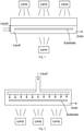
- Fig. 1 illustrates a single wafer chamber designed for examples of the present cyclic nucleation process.
- the substrate is submerged within the chamber with liquid entering from the side, and drained from another side.
- a plurality of heat lamps are installed for heating the substrate.
- Other configurations can also be implemented, for example, the heat lamps are installed in only one side, the heat lamp can be replaced with a resistive heating such as a heat chuck, the liquid can enter from the top, the substrate can touch the bottom wall of the chamber, the liquid can flow through the substrate without submerging the substrate, or the substrate can be rotated.
- Fig. 2 illustrates another exemplary process chamber using a showerhead for introducing the fluid. Additionally, the liquid can enter from a side, and the substrate can be submerged.
- Fig. 3 illustrates a rotating chamber roof example where the chamber roof can be rotated, together with a rotating substrate.
- the cleaning liquid can enter from the top of the rotating roof, and exhausts to the liquid drain through centrifugal force.
- Vacuum pump can remove gas and vapor from the chamber.
- Fig. 4 illustrates another exemplary single wafer cyclic nucleation cleaning chamber.
- Various mixtures of cleaning fluid can be jetted, sprayed or flowed onto a rotating substrate. Due to the centrifugal force, the fluid is exhausted to a liquid drain, and the vapor can be pumped out with a vacuum pump. Heat lamps can be used to change the temperature of the substrate or the fluid.
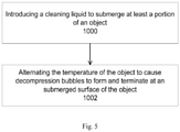
- Fig. 5 illustrates a process for treating an object employing the cyclic nucleation process with thermal cycle nucleation.
- Operation 1000 introduces a cleaning liquid to submerge at least a portion of the object.
- the liquid can be introduced through a showerhead, or an injection port such as a center injection inlet.
- the cleaning liquid can be a solvent.
- the cleaning liquid can be introduced with a vapor phase for equalizing the pressure before proceeding with a liquid phase.
- Operation 1002 alternates the temperature of the object to cause decompression bubbles to form and terminate at a submerged surface of the object.
- the decompression bubbles treat the object in a desirable manner, such as cleaning the surface, by generating energy from the termination of the bubbles.
- the termination of the bubbles can comprise collapsing, detaching, or imploding the bubbles.
- the alternation of object temperature can cause the decompression bubbles to cyclically form and terminate on a surface of the object.
- the alternation of temperature can be accompanied by an alternation of pressure and chemical active liquid flow to aid in the forming and terminating of the bubbles.
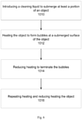
- Fig. 6 illustrates another example process for treating an object with thermal cycle nucleation.
- Operation 1010 introduces a cleaning liquid to submerge at least a portion of the object.
- Operation 1012 supplies thermal energy to the object to heat the object to form bubbles at a submerged surface of the object.
- the heating of the object can heat the liquid at the vicinity of the object surface, causing bubbles to form.
- Operation 1014 reduces the thermal energy, or cools the object, to terminate the bubbles, providing energy to the object surface for treating the object.
- the cycle can be repeated in operation 1016 with heating/reducing heating (or heating and cooling) the object for forming and terminating the bubbles.
- the heating can be performed by lamp heating for fast cycling.
- Fig. 7 illustrates an example for treating the object employing both pressure and temperature/heating cycling.
- Operation 1020 introduces a cleaning liquid to submerge at least a portion of the object in a process chamber.
- Operation 1022 alternates pressure and vacuum within the process chamber to cause decompression bubbles to form and terminate at a submerged surface of the object.
- the pressure values can oscillate between a high pressure and a low pressure values.
- the pressure can be atmospheric, sub-atmospheric, or above atmospheric levels.
- the vacuum levels can be sub-atmospheric, in the ranges of ten Torr, Torr, or sub-Torr pressure.
- Operation 1024 heats the object during the pressure phase to aid in the generation of bubbles.
- Operation 1026 reduces heating, or cools, the object to aid in the termination of the bubbles.
- the present invention applies in a cyclical manner, different chemical solutions/vapor to either create, grow vapor bubbles to treat the surface by collapse or implosion of vapor bubbles on the surfaces of an object.
- the process can selective grow vapor bubbles of one chemistry and implode or collapse with the stopping of the chemistry, or the introduction of a different vapor or liquid for treat of the first vapor or fluid. This can be followed by additional fluid or vapor for treatment of the additional cycles.
- This specific process is named Chemical Cycle Nucleation (CNP).
- CNP Chemical Cycle Nucleation
- varying concentrations fluid mixtures of chemical vapors/fluids can be applied in an alternating manner to either create or grow vapor bubbles to treat the surface by collapse or implode vapor bubbles on the surfaces of an object.
- Processing with CNP can provide additional benefits, such as the treated surfaces remain wet during cycling vapors/fluids or alternating concentrations. Further, the cycling and alternating fluid concentration of different chemical vapors or liquids form chemical mixtures directly on surfaces that are compounded to inhibit or eliminate redeposition of particle and complex chemical formulation such as photoresist, adhesives, polymer coatings, electronic fluxes. Chemical mixtures can be tailored to promote rapid chemical dissolving and breakdown of the complex chemical bonding of the surface contaminates.
- the present CNP process can enhance the basic nucleation-forming technology, and under certain conditions and applications the cycling different chemical vapors or liquid can inhibit or eliminate redeposition of particle and specific complex chemical formulation such as photoresist, adhesives, polymer coatings, electronic fluxes and promote breakdown of the chemical bonding structure to promote rapid dissolving or displacement of said contaminates.
- Sub micron particle removal from wafers will probably require 5 available mechanisms. Forced convection, bubble implosion, rapid evaporation, chemical adhesion and chemical etching may all be required.
- the new process can utilize the cycling of multiple fluids/vapors to treat surfaces of an object, using a vacuum chamber for a batch process or a single wafer process.
- An example of the new CNP process would be in the removal of Photo-Resist from Semiconductor Wafers:
- An enclosed solvent or aqueous chemical cycle nucleation (CNP) system includes a chamber for holding a wafer to be processed. At least one vacuum pump applies a negative gauge pressure to the chamber to remove air and other non-condensable gases. Means are provided for introducing a solvent to the evacuated chamber to submerge the wafer contained within.
- the solvent is comprised of organic medium used to dissolve the resist and an inorganic solution such as a peroxide or acid used to oxidize the carbon element of the resist.
- a first system removes pressure from the chamber to produce vapor bubbles for agitation and disruption of the boundary layer surrounding the resist and to vaporize the inorganic component for faster reaction in the vapor state.
- a second solvent is introduced to the chamber and a second system removes pressure from the chamber to produce vapor bubbles for agitation and rinsing of the wafer.
- the system includes recovery of the solvent from the chamber and wafer.
- Fig. 8 illustrates an embodiment for treating an object with the present cyclic nucleation process employing chemical cycle nucleation.
- Operation 1030 flows a chemical active agent or liquid to submerge at least a portion of the object, wherein the chemical active liquid promotes forming bubbles at a submerged surface.
- the chemical active liquid can be an oxidizer, a liquid with high bubble formation, or a liquid with lower vapor pressure. Exemplary chemical active liquids include peroxide chemicals, alkalines, solvents or acids.
- Operation 1032 stops the flow of the chemical active liquid to promote terminating the bubbles, or to help slow down or speed up the generation of bubbles.
- the process is repeated in operation 1034 with the cyclic pulsing of the chemical active liquid.
- the chemical active liquid is pulsed to the process chamber where the object is positioned.
- the chemical active liquid is injected to a cleaning liquid to promote generating bubbles, retard growing bubbles, enhance diffusion or inhibit diffusion.
- Fig. 9 illustrates another embodiment for treating an object with the present cyclic nucleation process employing chemical cycle nucleation.
- Operation 1040 flows a chemical active agent or liquid to submerge at least a portion of the object, wherein the chemical active liquid promotes forming bubbles at a submerged surface.
- Operation 1042 flows another liquid to promote terminating the bubbles. This other liquid can be a cleaning liquid, a solvent, or an actively bubble terminating liquid.
- Operation 1044 repeats the cycle until a desired result is achieved.
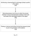
- Fig. 10 illustrates an exemplary embodiment of the present invention.
- Operation 1050 introduces a cleaning liquid to submerge at least a portion of the object.
- Operation 1052 alternates pressure and vacuum within the process chamber to cause decompression bubbles to form and terminate at a submerged surface of the object.
- Operation 1054 flows a chemical active liquid during the pressure phase to aid in the generation of bubbles.
- An exemplary system for treating a semi-conductor wafer for photo-resist removal in an enclosed solvent vacuum cycle nucleation processing system includes two solvent supply systems in sealable communication with a processing chamber comprises the steps of:
- the CNP process can utilize alternating the different concentrations of multiple fluids mixtures/vapors to treat surfaces of an object.
- An example of the new CNP process would in the removal of complex molecular chain structured material such as a polymer and/or adhesive from an object:
- An enclosed solvent or aqueous chemical cycle nucleation (CNP) system includes a chamber for holding a wafer to be processed. At least one vacuum pump applies a negative gauge pressure to the chamber to remove air and other non-condensable gases. Means are provided for introducing a solvent mixture of .01% up to 30% of oxidizer such as hydrogen peroxide and NMP to the evacuated chamber covering surfaces of object.
- CNP fluids can be introduced in a jet/vapor or as a fluid.
- the solvent/oxidizer mixture of organic medium used to dissolve the complex chemical bonds of the long molecular chain contaminates such as find in polymer, adhesives and electronic fluxes and an inorganic solution such as a peroxide or acid used to oxidize the carbon element.
- a first system removes pressure from the chamber to produce vapor bubbles for agitation and disruption of the boundary layer surrounding the polymer and to vaporize the inorganic component for faster reaction in the vapor state.
- a second solvent mixture is introduced to the chamber and a second system removes pressure from the chamber to produce vapor bubbles for agitation and rinsing of the object.
- the system includes recovery of the solvent from the chamber and object.
- This CNP enhancement is invented to target difficult to remove materials from surfaces by alternating concentration of solvent mixtures and with recovery of said mixtures.
- An exemplary system for treating a object in an enclosed solvent vacuum cycle nucleation processing system includes two or more solvent mixture supply systems in sealable communication with a processing chamber comprises the steps of:
Landscapes
- Engineering & Computer Science (AREA)
- Microelectronics & Electronic Packaging (AREA)
- Condensed Matter Physics & Semiconductors (AREA)
- General Physics & Mathematics (AREA)
- Manufacturing & Machinery (AREA)
- Computer Hardware Design (AREA)
- Physics & Mathematics (AREA)
- Power Engineering (AREA)
- Health & Medical Sciences (AREA)
- Toxicology (AREA)
- Cleaning Or Drying Semiconductors (AREA)
- Cleaning By Liquid Or Steam (AREA)
- Chemical Vapour Deposition (AREA)
Claims (3)
- Procédé de traitement d'un objet dans une chambre de processus, comprenant :l'introduction d'un liquide de nettoyage pour immerger au moins une partie de l'objet (1050) ;l'alternance de pression et de vide à l'intérieur de la chambre de processus pour provoquer la formation de bulles de décompression et leur arrêt au niveau d'une surface immergée de l'objet (1052) ; etcaractérisé par l'écoulement d'un liquide ou d'un agent chimique actif pour aider à générer des bulles au niveau de la surface de l'objet (1054).
- Procédé selon la revendication 1, comprenant uniquement l'une des étapes suivantes :- l'élimination du liquide de nettoyage de la surface de l'objet ;- la reconstitution du liquide de nettoyage après avoir éliminé le liquide de nettoyage de la surface de l'objet ;- le rinçage du liquide chimique actif du liquide de nettoyage pour aider à éliminer les bulles ;- le chauffage de l'objet pour aider à former les bulles au niveau de la surface immergée de l'objet ;- la réduction du chauffage pour aider à arrêter les bulles.
- Procédé selon l'une des revendications précédentes, caractérisé en ce que le liquide chimique actif est soit un peroxyde, soit un acide.
Applications Claiming Priority (2)
| Application Number | Priority Date | Filing Date | Title |
|---|---|---|---|
| US98315807P | 2007-10-27 | 2007-10-27 | |
| PCT/US2008/081397 WO2009055834A2 (fr) | 2007-10-27 | 2008-10-27 | Procédé de nucléation cyclique |
Publications (3)
| Publication Number | Publication Date |
|---|---|
| EP2212906A2 EP2212906A2 (fr) | 2010-08-04 |
| EP2212906A4 EP2212906A4 (fr) | 2014-09-17 |
| EP2212906B1 true EP2212906B1 (fr) | 2022-02-16 |
Family
ID=40580453
Family Applications (1)
| Application Number | Title | Priority Date | Filing Date |
|---|---|---|---|
| EP08842674.7A Active EP2212906B1 (fr) | 2007-10-27 | 2008-10-27 | Procédé de nucléation cyclique |
Country Status (5)
| Country | Link |
|---|---|
| US (1) | US20100192978A1 (fr) |
| EP (1) | EP2212906B1 (fr) |
| KR (1) | KR20100106321A (fr) |
| CN (1) | CN101911261B (fr) |
| WO (1) | WO2009055834A2 (fr) |
Families Citing this family (13)
| Publication number | Priority date | Publication date | Assignee | Title |
|---|---|---|---|---|
| WO2009055834A2 (fr) | 2007-10-27 | 2009-04-30 | Hyperflo Llc | Procédé de nucléation cyclique |
| JP5254308B2 (ja) * | 2010-12-27 | 2013-08-07 | 東京エレクトロン株式会社 | 液処理装置、液処理方法及びその液処理方法を実行させるためのプログラムを記録した記録媒体 |
| CN102618933A (zh) * | 2011-01-30 | 2012-08-01 | 上海思恩电子技术有限公司 | 硅材料的压差湿处理装置及其处理方法 |
| WO2013102857A1 (fr) * | 2012-01-02 | 2013-07-11 | Hyperflo Llc | Procédés et systèmes de nettoyage de transport de nucléation cyclique (cnx) |
| WO2013158802A1 (fr) * | 2012-04-18 | 2013-10-24 | Advanced Wet Technogogies Gmbh | Chambre dynamique pour technologie de nucléation par cycle |
| US20130291901A1 (en) * | 2012-05-06 | 2013-11-07 | Advanced Wet Technologies Gmbh | Hyperbaric Methods and Systems for Surface Treatment, Cleaning, and Drying |
| WO2014052508A1 (fr) * | 2012-09-25 | 2014-04-03 | Advanced Wet Technogogies Gmbh | Concept, méthodes et appareil de cnx à déplacement et expansion de gaz |
| US10022189B2 (en) | 2013-12-16 | 2018-07-17 | Stryker Sustainability Solutions, Inc. | Apparatus and method for cleaning an instrument |
| DE102015104147B4 (de) | 2015-03-19 | 2019-09-12 | Osram Opto Semiconductors Gmbh | Verfahren zur Ablösung eines Aufwachssubstrats von einer Schichtenfolge |
| KR102062873B1 (ko) * | 2015-10-04 | 2020-01-06 | 어플라이드 머티어리얼스, 인코포레이티드 | 작은 열 질량의 가압 챔버 |
| WO2019185837A1 (fr) * | 2018-03-28 | 2019-10-03 | Lpw Reinigungssysteme Gmbh | Procédé et dispositif de mise à disposition d'un milieu par nucléation cyclique |
| CN109301032A (zh) * | 2018-09-28 | 2019-02-01 | 横店集团东磁股份有限公司 | 单晶硅表面制绒方法 |
| WO2021055743A1 (fr) * | 2019-09-20 | 2021-03-25 | Carbon, Inc. | Nettoyage d'objets fabriqués de manière additive par nucléation cyclique sous vide |
Citations (7)
| Publication number | Priority date | Publication date | Assignee | Title |
|---|---|---|---|---|
| DE2932401A1 (de) | 1978-08-09 | 1980-02-21 | Atomic Energy Authority Uk | Verfahren zum herausloesen von material |
| EP0543322A1 (fr) | 1991-11-22 | 1993-05-26 | Aichelin Gmbh | Procédé pour le nettoyage des parts métalliques |
| US5868898A (en) | 1996-11-21 | 1999-02-09 | Taiwan Semiconductor Manufacturing Company, Ltd. | Fluid dispensing device for wet chemical process tank and method of using |
| US6418942B1 (en) | 2000-03-10 | 2002-07-16 | Donald Gray | Solvent and aqueous decompression processing system |
| US20050081884A1 (en) | 2003-10-15 | 2005-04-21 | Infineon Technologies North America Corp. | Semiconductor device cleaning employing heterogeneous nucleation for controlled cavitation |
| US20070107748A1 (en) | 2005-11-16 | 2007-05-17 | Donald Gray | Vacuum cavitational streaming |
| WO2009055834A2 (fr) | 2007-10-27 | 2009-04-30 | Hyperflo Llc | Procédé de nucléation cyclique |
Family Cites Families (12)
| Publication number | Priority date | Publication date | Assignee | Title |
|---|---|---|---|---|
| JP2777498B2 (ja) * | 1991-12-06 | 1998-07-16 | 三菱電機株式会社 | 基板の洗浄方法 |
| US5301701A (en) * | 1992-07-30 | 1994-04-12 | Nafziger Charles P | Single-chamber cleaning, rinsing and drying apparatus and method therefor |
| JPH06252115A (ja) * | 1993-02-23 | 1994-09-09 | Tamotsu Mesaki | 被洗浄物の洗浄方法 |
| US6253775B1 (en) * | 1998-06-04 | 2001-07-03 | Tokyo Electron Limited | Cleaning apparatus |
| JP2001246337A (ja) * | 2000-03-09 | 2001-09-11 | Mitsubishi Electric Corp | 微細孔を有する部品の湿式表面処理方法 |
| US6743300B2 (en) * | 2002-01-15 | 2004-06-01 | Donald Gray | Multistep single chamber parts proceeding method |
| US6783601B2 (en) * | 2002-06-06 | 2004-08-31 | Donald Gray | Method for removing particles and non-volatile residue from an object |
| US6802137B1 (en) * | 2003-11-25 | 2004-10-12 | Donald Gray | Solvent drying method |
| JP2005166906A (ja) * | 2003-12-02 | 2005-06-23 | Dainippon Screen Mfg Co Ltd | 基板洗浄装置および基板洗浄方法 |
| EP1717344A4 (fr) * | 2004-01-23 | 2008-08-20 | Ebara Corp | Procede de traitement de substrat, liquide de processus catalytique et appareil de traitement de substrat |
| DE112004002879A5 (de) * | 2004-03-22 | 2007-05-24 | Rena Sondermaschinen Gmbh | Verfahren zur Behandlung von Substratoberflächen |
| US7444761B2 (en) * | 2006-03-06 | 2008-11-04 | Gray Donald J | Intrinsically safe flammable solvent processing method and system |
-
2008
- 2008-10-27 WO PCT/US2008/081397 patent/WO2009055834A2/fr active Application Filing
- 2008-10-27 CN CN2008801223550A patent/CN101911261B/zh active Active
- 2008-10-27 KR KR1020107011653A patent/KR20100106321A/ko not_active Application Discontinuation
- 2008-10-27 US US12/259,294 patent/US20100192978A1/en not_active Abandoned
- 2008-10-27 EP EP08842674.7A patent/EP2212906B1/fr active Active
Patent Citations (7)
| Publication number | Priority date | Publication date | Assignee | Title |
|---|---|---|---|---|
| DE2932401A1 (de) | 1978-08-09 | 1980-02-21 | Atomic Energy Authority Uk | Verfahren zum herausloesen von material |
| EP0543322A1 (fr) | 1991-11-22 | 1993-05-26 | Aichelin Gmbh | Procédé pour le nettoyage des parts métalliques |
| US5868898A (en) | 1996-11-21 | 1999-02-09 | Taiwan Semiconductor Manufacturing Company, Ltd. | Fluid dispensing device for wet chemical process tank and method of using |
| US6418942B1 (en) | 2000-03-10 | 2002-07-16 | Donald Gray | Solvent and aqueous decompression processing system |
| US20050081884A1 (en) | 2003-10-15 | 2005-04-21 | Infineon Technologies North America Corp. | Semiconductor device cleaning employing heterogeneous nucleation for controlled cavitation |
| US20070107748A1 (en) | 2005-11-16 | 2007-05-17 | Donald Gray | Vacuum cavitational streaming |
| WO2009055834A2 (fr) | 2007-10-27 | 2009-04-30 | Hyperflo Llc | Procédé de nucléation cyclique |
Non-Patent Citations (3)
| Title |
|---|
| ANSPRÜCHE USPTO |
| FINAL REJECTION DES USPTO, 15 February 2012 (2012-02-15) |
| NON-FLNAL REJECTION DES USPTO, 17 August 2011 (2011-08-17) |
Also Published As
| Publication number | Publication date |
|---|---|
| EP2212906A4 (fr) | 2014-09-17 |
| WO2009055834A3 (fr) | 2009-06-11 |
| EP2212906A2 (fr) | 2010-08-04 |
| WO2009055834A2 (fr) | 2009-04-30 |
| KR20100106321A (ko) | 2010-10-01 |
| US20100192978A1 (en) | 2010-08-05 |
| CN101911261A (zh) | 2010-12-08 |
| CN101911261B (zh) | 2012-05-30 |
Similar Documents
| Publication | Publication Date | Title |
|---|---|---|
| EP2212906B1 (fr) | Procédé de nucléation cyclique | |
| KR100584105B1 (ko) | 농축 프로세싱 유체와 초음파 에너지를 사용한 반도체구성 요소의 처리 방법 | |
| US7033068B2 (en) | Substrate processing apparatus for processing substrates using dense phase gas and sonic waves | |
| JP5019370B2 (ja) | 基板の洗浄方法および洗浄装置 | |
| US9070722B2 (en) | System and method for the sonic-assisted cleaning of substrates utilizing a sonic-treated liquid | |
| KR20040075323A (ko) | 단일- 또는 두-기판 처리용 장치 및 방법 | |
| EP0419464A1 (fr) | Procede de nettoyage de surface et de fluide | |
| US20080017219A1 (en) | Transducer assembly incorporating a transmitter having through holes, and method and system for cleaning a substrate utilizing the same | |
| JP2017038029A (ja) | 基板洗浄方法および基板洗浄装置 | |
| WO2013158937A1 (fr) | Procédés et systèmes hyperbares pour rincer et sécher des matériaux granulaires | |
| US20080245390A1 (en) | Method for cleaning semiconductor wafer surfaces by applying periodic shear stress to the cleaning solution | |
| JP2007273806A (ja) | 半導体基板の洗浄方法および洗浄装置 | |
| WO2005006396A2 (fr) | Nettoyage megasonique utilisant une solution de nettoyage sursaturee | |
| US20050161059A1 (en) | Megasonic cleaning using supersaturated cleaning solution | |
| US20050034745A1 (en) | Processing a workpiece with ozone and a halogenated additive | |
| US20130056038A1 (en) | Wet Surface Treatment By Usage of a Liquid Bath Containing Energy Limited Bubbles | |
| JP2006162866A (ja) | レジスト膜の除去方法及びレジスト膜除去装置 | |
| US11911807B2 (en) | Method and apparatus for cleaning substrates | |
| JP2002001243A (ja) | 電子材料の洗浄方法 | |
| JP2006156472A (ja) | レジスト膜の除去方法およびレジスト膜除去装置 | |
| JP7437499B2 (ja) | 基板の洗浄方法及び洗浄装置 | |
| JP7217280B2 (ja) | 基板の洗浄方法及び洗浄装置 | |
| WO2013163352A1 (fr) | Transport cyclique par nucléation hyperbare pour appareils et procédés intégrés de nettoyage, d'élimination de colle et de séchage après le tranchage | |
| Snitovskii | Silicon surface cleaning by wet etching for IC production in a closed manufacturing system | |
| JP2005294855A (ja) | エッチング表面の親水性化方法 |
Legal Events
| Date | Code | Title | Description |
|---|---|---|---|
| PUAI | Public reference made under article 153(3) epc to a published international application that has entered the european phase |
Free format text: ORIGINAL CODE: 0009012 |
|
| 17P | Request for examination filed |
Effective date: 20100527 |
|
| AK | Designated contracting states |
Kind code of ref document: A2 Designated state(s): AT BE BG CH CY CZ DE DK EE ES FI FR GB GR HR HU IE IS IT LI LT LU LV MC MT NL NO PL PT RO SE SI SK TR |
|
| AX | Request for extension of the european patent |
Extension state: AL BA MK RS |
|
| DAX | Request for extension of the european patent (deleted) | ||
| RAP1 | Party data changed (applicant data changed or rights of an application transferred) |
Owner name: ADVANCED WET TECHNOLOGIES GMBH |
|
| A4 | Supplementary search report drawn up and despatched |
Effective date: 20140814 |
|
| RIC1 | Information provided on ipc code assigned before grant |
Ipc: H01L 21/304 20060101ALI20140808BHEP Ipc: H01L 21/02 20060101ALI20140808BHEP Ipc: B08B 3/10 20060101ALI20140808BHEP Ipc: H01L 21/67 20060101ALI20140808BHEP Ipc: H01L 21/302 20060101AFI20140808BHEP |
|
| 18D | Application deemed to be withdrawn |
Effective date: 20150313 |
|
| 19U | Interruption of proceedings before grant |
Effective date: 20150401 |
|
| D18D | Application deemed to be withdrawn (deleted) | ||
| 19W | Proceedings resumed before grant after interruption of proceedings |
Effective date: 20160601 |
|
| D17P | Request for examination filed (deleted) | ||
| RAP1 | Party data changed (applicant data changed or rights of an application transferred) |
Owner name: LPW REINIGUNGSSYSTEME GMBH |
|
| R17P | Request for examination filed (corrected) |
Effective date: 20100527 |
|
| STAA | Information on the status of an ep patent application or granted ep patent |
Free format text: STATUS: EXAMINATION IS IN PROGRESS |
|
| 17Q | First examination report despatched |
Effective date: 20180702 |
|
| REG | Reference to a national code |
Ref country code: DE Ref legal event code: R079 Ref document number: 602008064397 Country of ref document: DE Free format text: PREVIOUS MAIN CLASS: H01L0021302000 Ipc: B08B0003100000 |
|
| RIC1 | Information provided on ipc code assigned before grant |
Ipc: B08B 3/00 20060101ALI20190108BHEP Ipc: B08B 3/10 20060101AFI20190108BHEP Ipc: H01L 21/304 20060101ALI20190108BHEP Ipc: H01L 21/67 20060101ALI20190108BHEP Ipc: H01L 21/02 20060101ALI20190108BHEP Ipc: H01L 21/302 20060101ALI20190108BHEP |
|
| STAA | Information on the status of an ep patent application or granted ep patent |
Free format text: STATUS: EXAMINATION IS IN PROGRESS |
|
| GRAP | Despatch of communication of intention to grant a patent |
Free format text: ORIGINAL CODE: EPIDOSNIGR1 |
|
| STAA | Information on the status of an ep patent application or granted ep patent |
Free format text: STATUS: GRANT OF PATENT IS INTENDED |
|
| INTG | Intention to grant announced |
Effective date: 20210907 |
|
| GRAS | Grant fee paid |
Free format text: ORIGINAL CODE: EPIDOSNIGR3 |
|
| GRAA | (expected) grant |
Free format text: ORIGINAL CODE: 0009210 |
|
| STAA | Information on the status of an ep patent application or granted ep patent |
Free format text: STATUS: THE PATENT HAS BEEN GRANTED |
|
| AK | Designated contracting states |
Kind code of ref document: B1 Designated state(s): AT BE BG CH CY CZ DE DK EE ES FI FR GB GR HR HU IE IS IT LI LT LU LV MC MT NL NO PL PT RO SE SI SK TR |
|
| REG | Reference to a national code |
Ref country code: CH Ref legal event code: EP |
|
| REG | Reference to a national code |
Ref country code: DE Ref legal event code: R096 Ref document number: 602008064397 Country of ref document: DE |
|
| REG | Reference to a national code |
Ref country code: AT Ref legal event code: REF Ref document number: 1468565 Country of ref document: AT Kind code of ref document: T Effective date: 20220315 |
|
| REG | Reference to a national code |
Ref country code: IE Ref legal event code: FG4D |
|
| REG | Reference to a national code |
Ref country code: NL Ref legal event code: FP |
|
| REG | Reference to a national code |
Ref country code: LT Ref legal event code: MG9D |
|
| PG25 | Lapsed in a contracting state [announced via postgrant information from national office to epo] |
Ref country code: SE Free format text: LAPSE BECAUSE OF FAILURE TO SUBMIT A TRANSLATION OF THE DESCRIPTION OR TO PAY THE FEE WITHIN THE PRESCRIBED TIME-LIMIT Effective date: 20220216 Ref country code: PT Free format text: LAPSE BECAUSE OF FAILURE TO SUBMIT A TRANSLATION OF THE DESCRIPTION OR TO PAY THE FEE WITHIN THE PRESCRIBED TIME-LIMIT Effective date: 20220616 Ref country code: NO Free format text: LAPSE BECAUSE OF FAILURE TO SUBMIT A TRANSLATION OF THE DESCRIPTION OR TO PAY THE FEE WITHIN THE PRESCRIBED TIME-LIMIT Effective date: 20220516 Ref country code: LT Free format text: LAPSE BECAUSE OF FAILURE TO SUBMIT A TRANSLATION OF THE DESCRIPTION OR TO PAY THE FEE WITHIN THE PRESCRIBED TIME-LIMIT Effective date: 20220216 Ref country code: HR Free format text: LAPSE BECAUSE OF FAILURE TO SUBMIT A TRANSLATION OF THE DESCRIPTION OR TO PAY THE FEE WITHIN THE PRESCRIBED TIME-LIMIT Effective date: 20220216 Ref country code: ES Free format text: LAPSE BECAUSE OF FAILURE TO SUBMIT A TRANSLATION OF THE DESCRIPTION OR TO PAY THE FEE WITHIN THE PRESCRIBED TIME-LIMIT Effective date: 20220216 Ref country code: BG Free format text: LAPSE BECAUSE OF FAILURE TO SUBMIT A TRANSLATION OF THE DESCRIPTION OR TO PAY THE FEE WITHIN THE PRESCRIBED TIME-LIMIT Effective date: 20220516 |
|
| PG25 | Lapsed in a contracting state [announced via postgrant information from national office to epo] |
Ref country code: PL Free format text: LAPSE BECAUSE OF FAILURE TO SUBMIT A TRANSLATION OF THE DESCRIPTION OR TO PAY THE FEE WITHIN THE PRESCRIBED TIME-LIMIT Effective date: 20220216 Ref country code: LV Free format text: LAPSE BECAUSE OF FAILURE TO SUBMIT A TRANSLATION OF THE DESCRIPTION OR TO PAY THE FEE WITHIN THE PRESCRIBED TIME-LIMIT Effective date: 20220216 Ref country code: GR Free format text: LAPSE BECAUSE OF FAILURE TO SUBMIT A TRANSLATION OF THE DESCRIPTION OR TO PAY THE FEE WITHIN THE PRESCRIBED TIME-LIMIT Effective date: 20220517 Ref country code: FI Free format text: LAPSE BECAUSE OF FAILURE TO SUBMIT A TRANSLATION OF THE DESCRIPTION OR TO PAY THE FEE WITHIN THE PRESCRIBED TIME-LIMIT Effective date: 20220216 |
|
| PG25 | Lapsed in a contracting state [announced via postgrant information from national office to epo] |
Ref country code: IS Free format text: LAPSE BECAUSE OF FAILURE TO SUBMIT A TRANSLATION OF THE DESCRIPTION OR TO PAY THE FEE WITHIN THE PRESCRIBED TIME-LIMIT Effective date: 20220616 |
|
| PG25 | Lapsed in a contracting state [announced via postgrant information from national office to epo] |
Ref country code: SK Free format text: LAPSE BECAUSE OF FAILURE TO SUBMIT A TRANSLATION OF THE DESCRIPTION OR TO PAY THE FEE WITHIN THE PRESCRIBED TIME-LIMIT Effective date: 20220216 Ref country code: RO Free format text: LAPSE BECAUSE OF FAILURE TO SUBMIT A TRANSLATION OF THE DESCRIPTION OR TO PAY THE FEE WITHIN THE PRESCRIBED TIME-LIMIT Effective date: 20220216 Ref country code: EE Free format text: LAPSE BECAUSE OF FAILURE TO SUBMIT A TRANSLATION OF THE DESCRIPTION OR TO PAY THE FEE WITHIN THE PRESCRIBED TIME-LIMIT Effective date: 20220216 Ref country code: DK Free format text: LAPSE BECAUSE OF FAILURE TO SUBMIT A TRANSLATION OF THE DESCRIPTION OR TO PAY THE FEE WITHIN THE PRESCRIBED TIME-LIMIT Effective date: 20220216 Ref country code: CZ Free format text: LAPSE BECAUSE OF FAILURE TO SUBMIT A TRANSLATION OF THE DESCRIPTION OR TO PAY THE FEE WITHIN THE PRESCRIBED TIME-LIMIT Effective date: 20220216 |
|
| REG | Reference to a national code |
Ref country code: DE Ref legal event code: R026 Ref document number: 602008064397 Country of ref document: DE |
|
| PLBI | Opposition filed |
Free format text: ORIGINAL CODE: 0009260 |
|
| PLAX | Notice of opposition and request to file observation + time limit sent |
Free format text: ORIGINAL CODE: EPIDOSNOBS2 |
|
| 26 | Opposition filed |
Opponent name: MAFAC-E. SCHWARZ GMBH & CO. KG Effective date: 20221115 Opponent name: ECOCLEAN GMBH Effective date: 20221115 Opponent name: KARL ROLL GMBH & CO. KG Effective date: 20221114 |
|
| PG25 | Lapsed in a contracting state [announced via postgrant information from national office to epo] |
Ref country code: SI Free format text: LAPSE BECAUSE OF FAILURE TO SUBMIT A TRANSLATION OF THE DESCRIPTION OR TO PAY THE FEE WITHIN THE PRESCRIBED TIME-LIMIT Effective date: 20220216 |
|
| PLBB | Reply of patent proprietor to notice(s) of opposition received |
Free format text: ORIGINAL CODE: EPIDOSNOBS3 |
|
| REG | Reference to a national code |
Ref country code: BE Ref legal event code: MM Effective date: 20221031 |
|
| PG25 | Lapsed in a contracting state [announced via postgrant information from national office to epo] |
Ref country code: LU Free format text: LAPSE BECAUSE OF NON-PAYMENT OF DUE FEES Effective date: 20221027 |
|
| P01 | Opt-out of the competence of the unified patent court (upc) registered |
Effective date: 20230529 |
|
| REG | Reference to a national code |
Ref country code: AT Ref legal event code: UEP Ref document number: 1468565 Country of ref document: AT Kind code of ref document: T Effective date: 20220216 |
|
| PG25 | Lapsed in a contracting state [announced via postgrant information from national office to epo] |
Ref country code: BE Free format text: LAPSE BECAUSE OF NON-PAYMENT OF DUE FEES Effective date: 20221031 |
|
| PG25 | Lapsed in a contracting state [announced via postgrant information from national office to epo] |
Ref country code: IE Free format text: LAPSE BECAUSE OF NON-PAYMENT OF DUE FEES Effective date: 20221027 |
|
| PGFP | Annual fee paid to national office [announced via postgrant information from national office to epo] |
Ref country code: NL Payment date: 20231023 Year of fee payment: 16 |
|
| PGFP | Annual fee paid to national office [announced via postgrant information from national office to epo] |
Ref country code: GB Payment date: 20231025 Year of fee payment: 16 |
|
| PGFP | Annual fee paid to national office [announced via postgrant information from national office to epo] |
Ref country code: IT Payment date: 20231031 Year of fee payment: 16 Ref country code: FR Payment date: 20231023 Year of fee payment: 16 Ref country code: DE Payment date: 20231218 Year of fee payment: 16 Ref country code: CH Payment date: 20231102 Year of fee payment: 16 Ref country code: AT Payment date: 20231019 Year of fee payment: 16 |
|
| PG25 | Lapsed in a contracting state [announced via postgrant information from national office to epo] |
Ref country code: HU Free format text: LAPSE BECAUSE OF FAILURE TO SUBMIT A TRANSLATION OF THE DESCRIPTION OR TO PAY THE FEE WITHIN THE PRESCRIBED TIME-LIMIT; INVALID AB INITIO Effective date: 20081027 |
|
| PG25 | Lapsed in a contracting state [announced via postgrant information from national office to epo] |
Ref country code: CY Free format text: LAPSE BECAUSE OF FAILURE TO SUBMIT A TRANSLATION OF THE DESCRIPTION OR TO PAY THE FEE WITHIN THE PRESCRIBED TIME-LIMIT Effective date: 20220216 |