EP2210822A2 - Réceptacle de rangement - Google Patents
Réceptacle de rangement Download PDFInfo
- Publication number
- EP2210822A2 EP2210822A2 EP10156901A EP10156901A EP2210822A2 EP 2210822 A2 EP2210822 A2 EP 2210822A2 EP 10156901 A EP10156901 A EP 10156901A EP 10156901 A EP10156901 A EP 10156901A EP 2210822 A2 EP2210822 A2 EP 2210822A2
- Authority
- EP
- European Patent Office
- Prior art keywords
- package
- storage container
- cover
- primary
- rear surface
- Prior art date
- Legal status (The legal status is an assumption and is not a legal conclusion. Google has not performed a legal analysis and makes no representation as to the accuracy of the status listed.)
- Granted
Links
Images


Classifications
-
- B—PERFORMING OPERATIONS; TRANSPORTING
- B25—HAND TOOLS; PORTABLE POWER-DRIVEN TOOLS; MANIPULATORS
- B25H—WORKSHOP EQUIPMENT, e.g. FOR MARKING-OUT WORK; STORAGE MEANS FOR WORKSHOPS
- B25H3/00—Storage means or arrangements for workshops facilitating access to, or handling of, work tools or instruments
- B25H3/02—Boxes
- B25H3/021—Boxes comprising a number of connected storage elements
- B25H3/023—Boxes comprising a number of connected storage elements movable relative to one another for access to their interiors
-
- B—PERFORMING OPERATIONS; TRANSPORTING
- B65—CONVEYING; PACKING; STORING; HANDLING THIN OR FILAMENTARY MATERIAL
- B65D—CONTAINERS FOR STORAGE OR TRANSPORT OF ARTICLES OR MATERIALS, e.g. BAGS, BARRELS, BOTTLES, BOXES, CANS, CARTONS, CRATES, DRUMS, JARS, TANKS, HOPPERS, FORWARDING CONTAINERS; ACCESSORIES, CLOSURES, OR FITTINGS THEREFOR; PACKAGING ELEMENTS; PACKAGES
- B65D75/00—Packages comprising articles or materials partially or wholly enclosed in strips, sheets, blanks, tubes or webs of flexible sheet material, e.g. in folded wrappers
- B65D75/28—Articles or materials wholly enclosed in composite wrappers, i.e. wrappers formed by associating or interconnecting two or more sheets or blanks
- B65D75/30—Articles or materials enclosed between two opposed sheets or blanks having their margins united, e.g. by pressure-sensitive adhesive, crimping, heat-sealing, or welding
- B65D75/32—Articles or materials enclosed between two opposed sheets or blanks having their margins united, e.g. by pressure-sensitive adhesive, crimping, heat-sealing, or welding one or both sheets or blanks being recessed to accommodate contents
- B65D75/321—Both sheets being recessed
- B65D75/323—Both sheets being recessed and forming several compartments
-
- B—PERFORMING OPERATIONS; TRANSPORTING
- B65—CONVEYING; PACKING; STORING; HANDLING THIN OR FILAMENTARY MATERIAL
- B65D—CONTAINERS FOR STORAGE OR TRANSPORT OF ARTICLES OR MATERIALS, e.g. BAGS, BARRELS, BOTTLES, BOXES, CANS, CARTONS, CRATES, DRUMS, JARS, TANKS, HOPPERS, FORWARDING CONTAINERS; ACCESSORIES, CLOSURES, OR FITTINGS THEREFOR; PACKAGING ELEMENTS; PACKAGES
- B65D77/00—Packages formed by enclosing articles or materials in preformed containers, e.g. boxes, cartons, sacks or bags
- B65D77/04—Articles or materials enclosed in two or more containers disposed one within another
- B65D77/0446—Articles or materials enclosed in two or more containers disposed one within another the inner and outer containers being rigid or semi-rigid and the outer container being of polygonal cross-section not formed by folding or erecting one or more blanks
-
- B—PERFORMING OPERATIONS; TRANSPORTING
- B65—CONVEYING; PACKING; STORING; HANDLING THIN OR FILAMENTARY MATERIAL
- B65D—CONTAINERS FOR STORAGE OR TRANSPORT OF ARTICLES OR MATERIALS, e.g. BAGS, BARRELS, BOTTLES, BOXES, CANS, CARTONS, CRATES, DRUMS, JARS, TANKS, HOPPERS, FORWARDING CONTAINERS; ACCESSORIES, CLOSURES, OR FITTINGS THEREFOR; PACKAGING ELEMENTS; PACKAGES
- B65D2201/00—Means or constructions for testing or controlling the contents
Definitions
- the present invention relates generally to storage containers, and more particularly to a storage container having a unique divider system and hinge configuration, and to a display device for tool accessory containers and related products and more particularly, to an interactive display for containers and related products
- Storage containers exist in many varieties and may be used to store, organize and transport various items such as fasteners, tool bits and other accessories.
- the storage container of the present invention is designed such that it may simplify the manufacturing of a storage container.
- Plastic storage containers can be typically manufactured fairly inexpensively, but often at the expense of being less rigid and providing less flexibility in adapting the storage container to store items of various sizes and shapes.
- a storage case When used to store tool bits, fasteners or accessories on a job site, a storage case must be built to be strong and durable so that if it is dropped, it does not break open and spill its contents.
- Storage containers often include a base portion and a cover portion hingedly connected to the base portion.
- molding a plastic cover with an integrated hinge portion would involve a first step of positioning a metal rod in the section of the die to consist of the hinge portion and a second step of removing the metal rod after the cover is molded to reveal the resultant continuous passage for the pin of the hinge.
- the base portion of the case would be molded in a similar fashion with the resultant hinge portion able to interfit with the hinge portion of the cover such that a pin may be inserted therethrough creating a hinged container. It would be desirable to mold the cover and base including the hinge side of a storage container each in a single step.
- a display package for a storage container having first and second sides hingedly coupled said display package comprising:
- the storage container in accordance with this invention provides an improved storage container and method to mold the same.
- the molding process incorporates strategically placed bores and apertures in a die.
- the bores and apertures are formed at right angles such that they cooperate to form a continuous passage able to accept a pin to form a hinge.
- a base, cover and two internal transparent lids are each constructed with the unique hinge configuration.
- the container includes internal lateral wall sections on the cover and base having tabs extending therefrom. Removable spacers slidably interfit with the tabs to allow the user to customize the interior of the container.
- the transparent lids of the internal compartment have slidable latches for engagement with inner slots of the cover and base.
- the latches are aligned such that both lids must be secured in the locked position prior to properly closing the storage container.
- Accessory containers are commonly used throughout the construction industry. Various containers are generally used to organize small parts such as drill bits, nails, fasteners and the like. In some instances, such small parts may be sold as a complete set with the container.
- the present invention is directed toward providing an interactive display device for effectively displaying the multiple piece count tool accessories included in the set as well as displaying and communicating the features and benefits of the container.
- the present invention provides a blister package having a cutout portion incorporated on a first side of an accessory container and an enclosure portion incorporated on the opposite side of the container.
- the enclosure portion captures the container between a front and rear surface of the blister package while the cutout portion allows a potential customer to manipulate the first side of the container about its hinge in a direction away from the display package. The interaction allows a potential customer to feel the container to gain a better appreciation of the product and its functions as a whole.
- Another second invention is also provided herein and comprises a display package for a storage container having first and second sides hingedly coupled, said display package comprising:
- Such a display package can include one or more of the following features:
- the front and rear surface of said display package can be thermoformed together around said complimentary channels. wherein an insert card is disposed between said front and rear surface of said display package, said insert card including product information thereon.
- a third invention is also provided herein and comprises a display package for a storage container having first and second sides hingedly coupled, said display package comprising:
- Such a display package may including one or more of the following features:
- the front and rear surface of said display package may be thermoformed together around said complimentary channels.
- a fourth invention is also provided herein and comprises a method of making a display package for a storage container having a cover and base portion coupled at a hinge, said method comprising:
- Such a method may include one or more of the following features:
- the method may further include fixing a sensor tag to said insert card.
- a fifth invention is also provided herein and comprises a storage container comprising:
- Such a storage container may include one or more of the following features:
- the latch of one of said first and second lids may abut the other latch of said first and second lids when in an unlocked position as said base and cover portions are pivoted from an open position toward a closed position thereby precluding the container from reaching said closed position.
- a sixth invention is also provided herein and comprises a storage container, comprising:
- a seventh invention is also provided herein and comprises a storage container comprising:
- the removable spacer may have a first end section, middle section, and second end section, said first and second end sections having a larger cross section than said middle section.
- An eighth invention is also provided herein and comprises a storage container comprising:
- a ninth invention is also provided herein and comprises a spacer for selectively locating within a storage container, said spacer comprising:
- Such a spacer may include one or more of the following features:
- the at least one slot may include first and second slots each having an inner wall extending from an outer edge of said first and second end sections, said inner wall of said first and second slots being substantially parallel to said middle section, said first and second slots further including an outer wall extending outwardly toward said outer walls of said respective first and second end section.
- a tenth invention is also provided herein and comprises a method of making a container, said method comprising:
- the method may further comprise:
- the method may further comprise:
- the method may further comprise:
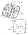
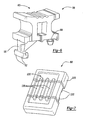
- the storage container 10 of the present invention includes a base 12 and a cover 14 hingedly attached to the base 12.
- a pair of transparent lids or cover plates 16, 18 are provided for selectively enclosing the storage area defined by the base 12 and cover 14, respectively.
- the cover 14 includes a cover surface 20, an inner surface 22, a top wall 24, side walls 26, 28 and a bottom wall 30.
- the base 12 includes a bottom surface 32, an inner surface 34, a top wall 36, side walls 38, 40 and bottom wall 42.
- the storage container 10 includes removable spacers 52 ( Fig. 1 and Fig. 5 ) that may be selectably positioned within the storage container to customize the interior space.
- Slidable latches 70, 70' releasably secure cover plates 16 and 18 to the base 12 and cover 14, respectively.
- Latch 80 releasably secures cover 14 to the base 12.
- Cover surface 20 is contoured to include upwardly extending portions 44.
- the inner surface 22 includes parallel dividers 46,56 extending between side walls 26,28.
- Parallel dividers 46, 56 and bottom wall 30 include tabs 48 extending therefrom.
- Tabs 48 are configured to engage fingers 50 of removable spacers 52 (best shown in Fig. 5 ).
- Opposing tabs 48a, 48b ( Fig. 2B ), are laterally offset a predetermined distance such that a readily available piece of material may be substituted for a spacer 52, in the event a spacer is misplaced.
- the predetermined distance is configured to be a distance common to readily available scrap pieces of material such as, but not limited to, 1/8 inch plywood.
- Bottom surface 30 includes integrated hinge member 76.
- a slot 58 is configured to accept a finger 98 on latch 70' (best shown in Figures 1 and 6 ) of cover plate 18.
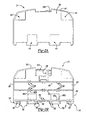
- the inner surface 34 of the base 12 is configured much the same as the cover 14.
- Base surface 32 includes recessed portions 54.
- the recessed portions 54 are coordinated to interfit with the upwardly extending portions 44 of cover 14 such that a series of cases 10 may be securely stacked.
- the inner surface 34 includes parallel dividers 64, 66 extending between side walls 38,40.
- Parallel dividers 64, 66 and bottom wall 42 include tabs 68 extending therefrom.
- Tabs 68 are configured to engage tabs 50 of removable spacers 52 (best shown in Figures 1 and 5 ).
- Opposing tabs 68a, 68b are laterally offset a predetermined distance such that a scrap piece of material may be substituted for a spacer 52 as described above.
- Base 12 includes integrated hinge member 86.
- a slot 120 is configured to accept finger 98 on latch 70 (best shown in Figures 1 and 6 ) of cover plate 16.
- the storage container 10 of the present invention allows the apertures of the hinge portion to be formed without the need of a metal rod for forming the apertures.
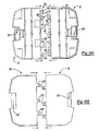
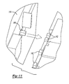
- the configuration of the cover 14 and the base 12 illustrated in Figures 2A-3E include hinge portions 76 and 86, respectively.
- the hinge member 76 of cover 14 includes tab portions 78 which are formed from a die configuration that creates cavity sections 82 ( Fig. 2B ) in a direction perpendicular to the plane of cover 14. Additionally, the die allows cavity sections 84 (viewed from Figure 2E ) to be formed in a direction parallel to the plane of cover 14 and in a location between cavity sections 82.
- the insert portions of the die are strategically located such that cavity sections 82 and 84 cooperate to form a continuous passage 88 ( Figures 2B and 2D ) which is created without the need for additional steps involving a metal rod die insert as is required with conventional hinge molding techniques.
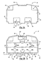
- the base 12 is molded in a similar fashion to create a continuous passage for a hinge pin.
- Tab portions 90 of hinge member 86 include cavity sections 92 ( Fig. 3B ) perpendicular from the plane of base 12. Accordingly, cavities 94 ( Fig. 3E ) are also incorporated in a direction parallel to the plane of base 12. Cavities 92 and 94 cooperate to form a continuous passage 96 ( Fig. 3B and Fig. 3D ).
- case 10 includes two symmetric transparent cover plates 16,18.
- the cover plates 16,18 are molded with the same hinge strategy as mentioned for the cover 14 and base 12.
- the tab portions 102 of hinge sections 100 include cavities 104 formed perpendicular to face 106 of cover plate 16,18 on a first side of the cover plates 16,18.
- Cavities 108 are also formed from the geometry of the die and are perpendicular to face 106 on a second side of the cover plates 16, 18. Cavities 104 and 108 are parallel to each other and offset which cooperate to form a continuous passage 110 ( Figure 4D ).
- the tab portions 102 of the cover plates are laterally offset such that a first cover plate 16 may be turned 180 degrees from a second cover plate 18 allowing the tab portions 102 to interfit.
- This feature allows both cover plates 16,18 to be molded from the same die.
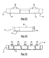
- Cover plates 16,18 include a slot 112 integrated thereon to accept slidable latches 70,70' ( Figs. 1 and 6 ).
- Cover plates 16, 18 further include a raised lip or edge 62.
- Raised edge 62 is preferably formed around the side walls 55 and at least a portion of the top wall 56 of the cover plates. Raised edge 62 provides increased structural strength and rigidity to cover plates 16, 18. In this manner, raised edge 62 resists twisting and fatigue associated with repeated manipulation of the cover plates. In a preferred orientation, the raised edge 62 extends toward inner surface 22 and 34 of the cover and base respectively.
- tab portions 90 of hinge 86 of the base 12 are offset from hinge portions 78 of cover 14 so as to interfit when mated. Furthermore, the tab portions 102 of the cover plates 16,18 are positioned between hinge members 86,76 of the base 12 and cover 14, respectively (placing Figure 8B onto Figure 8A to create Figure 1 ). The respective hinge portions 90 of base 12, 78 of cover 14 and 102 of cover plates 16,18 interfit to define one continuous passage 114 aligned to accept a hinge pin 130 ( Figure 1 ).
- Hinge pin 130 is preferably made of a rigid material such as metal. Hinge pin 130 is zinc coated to provide increased lubricity during installation. The zinc coating further inhibits premature rusting or corrosion of the hinge.
- Spacer 52 includes flared arms 116 having fingers 50 extending therefrom.
- the fingers 50 are adapted to slidably engage tabs 48 of cover 14 or tabs 68 of base 12.
- the spacers are made from a flexible material such as soft rubber or other elastomeric material.
- the flared arms 116 of spacers 52 are contoured such that an object may be easily removed from the box without becoming caught in a 90 degree corner of an inner compartment.
- the internal configuration also provides shock resistance in the event of a drop or sudden impact.
- Cover plate 16 includes a latch 70 slidably engaged with slot 112.
- the latch 70 (best shown in Fig. 6 ), includes body 74, having an arm 98 and outwardly extending fingers 72 and tang 99. Wing section 60 has a contoured surface to enhance grip while sliding latch 70. Latch 70 is slidably engaged to slot 112 of cover plate 16. When a cover plate 16 is in its closed position, latch 70 may be laterally moved such that fingers 72 of arm 98 engage the rear surface of slot 120 securing the cover plate 16 to base 12 in a locked position.
- the second cover plate 18 (identical to the first cover plate but flipped 180 degrees) also includes a slot 112' and latch 70'.
- the latch 70' slidably engages slot 58 of cover 14 when in a locked position.
- the relationship of latches 70, 70' to cover plates 16 and 18 are such that the latches 70,70' of the cover plates 16,18 must be in a locked position in order for the carrying case 5 to properly close.
- the wing 60 of latches 70, 70' will abut against one another preventing the case 10 from properly closing.
- the cover 14 includes a slidable latch 80.
- the slidable latch 80 includes outer circumferential wall 128 including fingers 122 for engagement with track 124 of base 12 and track 105 on cover 14. Ribs 118 laterally extend from face 126 of latch 80 to improve grip.
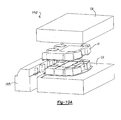
- the tool 140 includes a first, second, and third die member 136, 144, and 138.
- Die 136 includes vertical pegs 142 extending therefrom.
- the base 12 is molded from a similar tool having a corresponding peg and tab arrangement which are offset from those of the cover tool 140 such that the molded parts cooperate to form a hinge. As such, a similar die arrangement is used to mold the cover plates 16, 18.
- a first die member 136 is provided having a series of pegs extending in a first direction.
- a second die member 144 is provided having a series of pegs extending in a second direction, the second direction being perpendicular to the first direction.
- the first and second die members are closably arranged into a mold position in tool 140, the pegs of the second die member 144 being arranged to extend between a pair of adjacent pegs of the first die member 136 in the mold position.
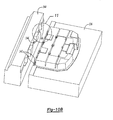
- Working material is admitted to tool 140.
- the working material is cured and the tool 140 is opened.
- a cover portion of the container is removed from tool 140.
- the cover portion includes a first continuous aperture formed along a series of cover tab members defining a first hinge portion, the first aperture extending in a third direction, the third direction being perpendicular to the first and second directions.
- a third die member is provided having a series of pegs extending in the first direction.
- a fourth die member is provided having a series of pegs extending in the second direction.
- the third and fourth die members are closably arranged into a mold position in tool 140, the pegs of the fourth die member being arranged to extend between a pair of adjacent pegs of the third die member in the mold position.
- Working material is admitted to tool 140.
- the working material is cured and the tool 140 is opened.
- the base portion 12 is removed and includes a second continuous aperture formed along a series of base tab members defining a second hinge portion, the second aperture extending in the third direction.
- lid 16 The preferred method of constructing lid 16 will now be described. As previously explained, construction of lid 18 is performed by the same method.
- a fifth die member having a series of pegs extending in the first direction is provided.
- a sixth die member is provided having a series of pegs extending in the second direction.
- the fifth and sixth die members are closably arranged into a mold position in tool 140, the pegs of the sixth die member being arranged to extend between a pair of adjacent pegs of the fifth die member in the mold position.
- Working material is admitted to tool 140. The working material is cured and the tool 140 is opened. Lid 16 is removed from the tool 140, the first lid including a third continuous aperture formed along a series of first lid tab members defining a third hinge portion, the third aperture extending in the third direction.
- the first aperture of the cover is aligned with the second aperture of the base revealing a continuous through-hole.
- the third aperture of the first lid 16 is aligned with the continuous through-hole thereby placing the first lid between the base 12 and cover 14.
- a second lid 18 is rotated lengthwise 180 degrees from lid 16.
- the fourth aperture of the second lid is aligned with the continuous through-hole thereby placing the second lid 18 adjacent the first lid 16 and between the base 12 and cover 14.
- Pin 130 is inserted through the continuous through-hole thereby hingedly connecting base 12, lids 16, 18 and cover 14.
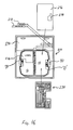
- Primary blister package 220 includes a 2-piece or clam shell plastic thermoformed blister hereinafter referred to as front and rear primary blister surfaces 222, 224, shown in Figs. 14 and 13 , respectively.
- Primary blister package 220 is configured to surround a secondary blister package 230 above the base 12 of the storage container 10.
- Secondary blister package 230 is also a 2-piece or clam shell plastic thermoformed blister hereinafter referred to as front and rear secondary blister surfaces 232, 234 respectively.
- Secondary blister package 230 contains a plurality of tool accessories 236 such as drill bits, screwdriver bits and the like.
- primary package 220 surrounds base 12 however it is appreciated that primary package 220 may alternatively surround cover 14.
- the cover surface (not specifically shown) of container 10 is bounded by rear blister surface 224.
- a cutout 238 is provided in the front blister surface 222 to provide access to cover plate 16.
- a potential purchaser or user may actuate latch 70 to gain access to the interior storage of cover 14.
- the interior features of the cover 14 may be manipulated including spacer 20.
- the cover 14 may be rotated toward a direction through cutout 238 about hinge 130. Accordingly, the user may interact with the container features to gain an understanding of the workability and usability of the container 10.
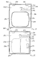
- Front primary blister 222 includes perimeter 240 having upper and lower edges 242, 244 and first and second side edges 246, 248. Perimeter 240 is further defined by ribbed channel 250 and outer flange 252 extending therearound. As will be described in further detail, ribbed channel 250 provides a sealing surface for mating front and rear primary blisters 222, 224 together.
- An upper portion 254 includes blister portions 256 incorporated to accept additional tool accessories 212 such as tool bit drive guides not included with secondary package 230. It will be appreciated that blister portions 256 may resemble alternate shapes to accommodate alternate desired accessories. Cutout 238 is incorporated on front primary blister 222 to allow for user interaction with container 10.
- Extension section 278 incorporates a depth sufficient to accept secondary blister package 230.
- extension dome 294 provides the depth sufficient to accommodates latch 80.
- Cutout sections 206 are incorporated in upper portion 254. Cutout sections 206 are configured to allow hanging posts (not shown) to extend therethough on a display shelf.
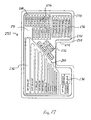
- Rear primary blister 224 includes perimeter 260 having upper and lower edges 262, 264 and first and second side edges 266, 268. Perimeter 260 is further defined by ribbed channel 270 and outer flange 272 extending therearound. Ribbed channel 270 has a depth and width sufficient to cooperatively interfit within ribbed channel 250 of front primary blister 222. Depressions 276 are arranged to compliment blister portions 256 of front primary blister 222. It is appreciated that additional tool accessories may alternatively be arranged to fit entirely within blisters 256 removing the need for depressions 276. Likewise, it may be desirable to arrange additional tool accessories entirely in depressions 276 allowing the complimentary portion of front primary blister 222 to remain flush.
- Cavity 286 is arranged on rear primary blister 224 to accommodate the footprint of entire container 10. As such, projection 282 is incorporated to accommodate latch 80. Blister portions 276 are incorporated in upper portion 258. Cutout sections 280 are complimentary with cutout sections 206 of front primary blister 222 and likewise align to allow hanging posts (not shown) to extend therethough on a display shelf.
- secondary blister package 230 includes cavities 288 arranged therein. Cavities 288 are preferably formed on rear secondary blister surface 234. Cavities 288 are prearranged in an optimized layout in secondary blister package 230 to accommodate the desired tool bits 236. Front and rear secondary blister surfaces 232, 234 are thermoformed together at predetermined locations thereon such as around perimeter 238. Alternatively, front and rear blister surfaces 232, 234 may include complimentary depressions (not shown) arranged on the interior. In this regard, front and rear blister surfaces 232, 234 may be thermoformed together along the complimentary depressions.
- insert card 290 is disposed between front and rear primary blister 222, 224 in an assembled condition.
- Insert card 290 is preferably positioned on upper portion 254 and incorporates cutouts 292 to cooperatively align with blister portions 256 and 276.
- insert card 290 includes cutouts 208 which align with cutouts 206 and 280 of front and rear primary blister surfaces 222 and 224 respectively.
- Insert card 290 includes product information such as a company name and contents of package 210.
- Insert card 290 includes UPC 202 and sensor tag 204. Sensor 204 is incorporated to cooperate with a stores security system to reduce theft.
- a divider card 296 is disposed between secondary blister package 230 and base 12 of container 10.
- Label 216 including further description of container 10 is adhesively attached to cover plate 16.
- Divider card 296 includes cutout 298 to accommodate latch 70' and latch 80.
- Insert card 290 and divider card 296 are constructed of rigid material such as cardboard.
- a label 216 further describing the features of the container 10 is adhesively disposed on cover plate 16, as shown in Figure 12 .
- display package 210 having container 10 retained therein will now be described. Again, while the following description is directed to placing base portion 12 on a common side as the secondary blister package 230, it is appreciated that secondary blister package 230 may be incorporated on a common side as the cover 14 of container 10. In this regard, extension dome 294 would not be required in a configuration having secondary blister package 230 on a common side as cover 14.
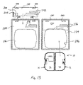
- insert card 290 is positioned onto upper portion 258 of rear primary blister 224.
- Container 10 is then deposited into cavity 286 orienting cover 14 on the left and base 12 on the right as viewed from Figure 13 .
- additional tool bits 212 are deposited into the depressions formed by the blister portions 276.
- Divider card 296 ( Figure 16 ) is placed onto cover plate 18 orienting cutout 298 in a location to receive latch 70 and latch 80 therethrough.
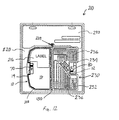
- Secondary blister package 230 is preferably assembled by placing tool bits 236 in respective cavities 288. After front and rear secondary blister surfaces 232, 234 are thermoformed together in the above discussed manner, the secondary blister package 230 is placed above divider card 296 allowing indent 274 ( Figure 17 ) to locate around latch 70 and latch 80, as shown in Figure 12 .
- Top primary blister surface 222 is finally positioned over rear primary blister surface 224 thereby capturing secondary blister package 230 therebetween.
- Front and rear primary blister surface 222, 224 are preferably thermoformed together around ribbed channels 250, 270.
- front and rear primary blister surfaces 222, 224 are thermoformed together at a spot seal 218 in a location adjacent hinge 130. The spot seal 218 is incorporated to provide additional mating support while discouraging access to secondary tool bits 212, insert card 290 and secondary blister package 230.
- the storage container and display package of the present invention are disclosed for use with a series of tool bit accessories, it should be understood that the storage container and display package can be used with other accessories such as, but not limited to, fishing tackle, pills, fasteners, sewing accessories, and other types of accessories that include multiple small pieces for which a storage container such as the one disclosed herein can be utilized.
- accessories such as, but not limited to, fishing tackle, pills, fasteners, sewing accessories, and other types of accessories that include multiple small pieces for which a storage container such as the one disclosed herein can be utilized.
- Such variations are not to be regarded as a departure from the spirit and scope of the invention, and all such modifications as would be obvious to one skilled in the art are intended to be included within the scope of the following claims.
Landscapes
- Engineering & Computer Science (AREA)
- Mechanical Engineering (AREA)
- Chemical & Material Sciences (AREA)
- Composite Materials (AREA)
- Packages (AREA)
- Closures For Containers (AREA)
- Cartons (AREA)
Applications Claiming Priority (2)
| Application Number | Priority Date | Filing Date | Title |
|---|---|---|---|
| US09/840,278 US7048133B2 (en) | 2001-04-23 | 2001-04-23 | Storage container |
| EP02764273A EP1389168A4 (de) | 2001-04-23 | 2002-04-22 | Lagerungsbehälter |
Related Parent Applications (2)
| Application Number | Title | Priority Date | Filing Date |
|---|---|---|---|
| EP02764273.5 Division | 2002-04-22 | ||
| EP02764273A Division EP1389168A4 (de) | 2001-04-23 | 2002-04-22 | Lagerungsbehälter |
Publications (3)
| Publication Number | Publication Date |
|---|---|
| EP2210822A2 true EP2210822A2 (de) | 2010-07-28 |
| EP2210822A3 EP2210822A3 (de) | 2012-07-18 |
| EP2210822B1 EP2210822B1 (de) | 2014-07-16 |
Family
ID=25281928
Family Applications (2)
| Application Number | Title | Priority Date | Filing Date |
|---|---|---|---|
| EP02764273A Withdrawn EP1389168A4 (de) | 2001-04-23 | 2002-04-22 | Lagerungsbehälter |
| EP10156901.0A Expired - Lifetime EP2210822B1 (de) | 2001-04-23 | 2002-04-22 | Lagerungsbehälter |
Family Applications Before (1)
| Application Number | Title | Priority Date | Filing Date |
|---|---|---|---|
| EP02764273A Withdrawn EP1389168A4 (de) | 2001-04-23 | 2002-04-22 | Lagerungsbehälter |
Country Status (4)
| Country | Link |
|---|---|
| US (4) | US7048133B2 (de) |
| EP (2) | EP1389168A4 (de) |
| CN (1) | CN1288039C (de) |
| WO (1) | WO2002085725A1 (de) |
Families Citing this family (90)
| Publication number | Priority date | Publication date | Assignee | Title |
|---|---|---|---|---|
| US7048133B2 (en) * | 2001-04-23 | 2006-05-23 | Black & Decker Inc. | Storage container |
| US7237673B2 (en) * | 2001-04-23 | 2007-07-03 | Black & Decker Inc. | Container for tool bits |
| US20050029139A1 (en) * | 2003-08-05 | 2005-02-10 | Kun-Chen Chen | Tool case |
| USD527051S1 (en) | 2003-08-22 | 2006-08-22 | Moy Gerard E | Hanging file folder box storage system |
| USD514807S1 (en) * | 2004-02-18 | 2006-02-14 | Black & Decker Inc. | Storage container |
| AU2005209652B2 (en) * | 2004-09-13 | 2010-03-18 | Buildsafe Australia Ip Pty Ltd | Ladder guard |
| US7370772B2 (en) * | 2004-09-30 | 2008-05-13 | Black & Decker Inc. | Large tough case extension case cover latch |
| US20060118562A1 (en) * | 2004-11-09 | 2006-06-08 | Jeffrey Plantz | Food containers with hinged handles |
| US20060124648A1 (en) * | 2004-12-10 | 2006-06-15 | Croft William F | Storage container assembly |
| US20080156671A1 (en) * | 2005-02-07 | 2008-07-03 | Conny Jansson | Case |
| US7401698B2 (en) * | 2005-02-22 | 2008-07-22 | Robert Bosch Gmbh | Latch for tool accessory case |
| US8066143B2 (en) * | 2005-02-22 | 2011-11-29 | Rehrig Pacific Company | Storage container with hinged lid |
| EP1736418A3 (de) * | 2005-05-24 | 2007-02-14 | Fulvio Soncini | Scharnier, insbesondere für Behälter |
| US7246556B1 (en) * | 2005-10-06 | 2007-07-24 | Safe-T Products, Inc. | Case for multiple stamp pads |
| US7784632B2 (en) * | 2005-10-27 | 2010-08-31 | Thai Vo Truong | Collapsible cargo organizer |
| USD555902S1 (en) * | 2006-04-27 | 2007-11-27 | Credo Technology Corporation | Case for tool accessories |
| USD553857S1 (en) * | 2006-04-27 | 2007-10-30 | Credo Technology Corporation | Case for tool accessories |
| US20080216809A1 (en) * | 2007-03-05 | 2008-09-11 | Brian Lee Begotka | Portable Outdoor Cooking Device |
| AU2008323621B2 (en) * | 2007-11-14 | 2012-08-16 | B.Box For Kids Developments Pty Ltd | Container for carrying diaper changing items |
| US8006860B2 (en) * | 2007-12-14 | 2011-08-30 | Marianne Christine Klein | Portable gum container |
| US20090173744A1 (en) * | 2008-01-03 | 2009-07-09 | Hassell Jon P | Container with lid |
| US20090223971A1 (en) * | 2008-03-05 | 2009-09-10 | Brian Moffett | Organizer for accessory items |
| USD588811S1 (en) | 2008-05-30 | 2009-03-24 | Black & Decker Inc. | Tool bit container |
| USD601797S1 (en) | 2008-06-03 | 2009-10-13 | Black & Decker Inc. | Tool storage case |
| USD600015S1 (en) | 2008-06-03 | 2009-09-15 | Black & Decker Inc. | Tool storage case |
| USD599112S1 (en) | 2008-06-03 | 2009-09-01 | Black & Decker Inc. | Tool storage case |
| US8342345B2 (en) * | 2008-11-20 | 2013-01-01 | Milwaukee Electric Tool Corporation | Accessory storage case |
| NZ581650A (en) * | 2008-12-04 | 2012-03-30 | Reece Pty Ltd | Hinged case having an internal compartment with a pivotable and slidable lid |
| USD608094S1 (en) | 2008-12-11 | 2010-01-19 | Black & Decker Inc. | Case for socket wrench accessories |
| US20110058356A1 (en) | 2009-02-25 | 2011-03-10 | Black & Decker Inc. | Power tool with light emitting assembly |
| US8317350B2 (en) | 2009-02-25 | 2012-11-27 | Black & Decker Inc. | Power tool with a light for illuminating a workpiece |
| US8328381B2 (en) | 2009-02-25 | 2012-12-11 | Black & Decker Inc. | Light for a power tool and method of illuminating a workpiece |
| US8056754B2 (en) * | 2009-05-27 | 2011-11-15 | Automotive Components Holdings, Llc | Movable cup holder divider |
| US8267245B2 (en) * | 2009-09-02 | 2012-09-18 | Black & Decker Inc. | Method and package for displaying magnetic tool container |
| US20110215097A1 (en) * | 2010-03-08 | 2011-09-08 | Archie Jr Willard Nelson | Dual compartment sandwich container and method of making same |
| US9028088B2 (en) | 2010-09-30 | 2015-05-12 | Black & Decker Inc. | Lighted power tool |
| US9328915B2 (en) | 2010-09-30 | 2016-05-03 | Black & Decker Inc. | Lighted power tool |
| US12059780B2 (en) | 2010-09-30 | 2024-08-13 | Black & Decker Inc. | Lighted power tool |
| US20120152944A1 (en) * | 2010-12-15 | 2012-06-21 | The Stanley Works Israel Ltd. | Sealable storage container |
| US9114909B2 (en) | 2011-02-04 | 2015-08-25 | Western Industries, Inc. | Storage container |
| JP5739266B2 (ja) * | 2011-05-09 | 2015-06-24 | 株式会社マキタ | 電動工具用収納ケース |
| CA2783455A1 (en) | 2011-07-20 | 2013-01-20 | Milwaukee Electric Tool Corporation | Hand tool |
| US8998031B2 (en) | 2011-08-26 | 2015-04-07 | Stericycle, Inc. | Waste container assembly |
| US8464869B2 (en) | 2011-11-14 | 2013-06-18 | Milwaukee Electric Tool Corporation | Tool case |
| GB2501456A (en) * | 2012-02-09 | 2013-10-30 | Lindi Jean Lawrenson | Folding multiple box unit |
| US9242355B2 (en) | 2012-04-17 | 2016-01-26 | Black & Decker Inc. | Illuminated power tool |
| US9539722B2 (en) | 2012-12-19 | 2017-01-10 | Milwaukee Electric Tool Corporation | Tool storage devices |
| US20140262884A1 (en) * | 2013-03-14 | 2014-09-18 | Apothecary Products, Inc. | Medicine storage arrangements and methods of assembly and use |
| US9884695B2 (en) * | 2013-03-28 | 2018-02-06 | Aesynt Incorporated | Compartment configured for presentation of stored articles |
| US9402783B2 (en) * | 2013-08-12 | 2016-08-02 | Erik Laibe | Multi-compartment container for the secure storage of therapeutic agents |
| USD721231S1 (en) | 2013-08-20 | 2015-01-20 | Milwaukee Electric Tool Corporation | Accessory case |
| WO2016003425A1 (en) * | 2014-06-30 | 2016-01-07 | Kimberly-Clark Worldwide, Inc. | Product display for multiple product configurations |
| US9616562B2 (en) | 2014-07-22 | 2017-04-11 | Milwaukee Electric Tool Corporation | Tool storage devices |
| USD740559S1 (en) | 2014-08-25 | 2015-10-13 | Milwaukee Electric Tool Corporation | Accessory case |
| US9694489B2 (en) | 2014-08-25 | 2017-07-04 | Milwaukee Electric Tool Corporation | Tool bit case with modular components |
| CN104760776B (zh) * | 2015-04-16 | 2017-04-26 | 苏州大森塑胶工业有限公司 | 可循环利用的物流包装箱 |
| USD810435S1 (en) | 2015-07-17 | 2018-02-20 | Milwaukee Electric Tool Corporation | Bag |
| USD834817S1 (en) | 2015-07-17 | 2018-12-04 | Milwaukee Electric Tool Corporation | Bag |
| USD844324S1 (en) | 2015-07-17 | 2019-04-02 | Milwaukee Electric Tool Corporation | Bag |
| US20170096264A1 (en) * | 2015-10-02 | 2017-04-06 | Shadonna K. Anderson | Apparatus for transporting goods and for providing mobile seating |
| US9872547B2 (en) | 2015-11-25 | 2018-01-23 | Milwaukee Electric Tool Corporation | Handle assembly for a case |
| CN105328672A (zh) * | 2015-11-27 | 2016-02-17 | 国网浙江省电力公司磐安县供电公司 | 一种多功能电力检修工具箱 |
| CN105291079A (zh) * | 2015-12-10 | 2016-02-03 | 国网四川雅安电力(集团)股份有限公司 | 一种便携式变电操作多功能手提箱 |
| US9380850B1 (en) * | 2015-12-16 | 2016-07-05 | Bonfit America Inc. | Safety razor holder with zinc strip to reduce corrosion of the razorblades |
| US9581341B1 (en) * | 2015-12-16 | 2017-02-28 | Bonfit America Inc. | Safety razor holder with zinc strip to reduce corrosion of the razorblades and interior leaf spring to facilitate retention of the razorblade cartridge within the razor holder |
| USD839449S1 (en) * | 2016-10-27 | 2019-01-29 | Keter Plastic Ltd. | Sawhorse |
| US20180126919A1 (en) * | 2016-11-09 | 2018-05-10 | Ford Global Technologies, Llc | Versatile cup and device holder |
| AT519403B1 (de) * | 2016-11-30 | 2022-07-15 | Colop Stempelerzeugung Skopek Gmbh & Co Kg | Stempelkisseneinheit |
| CN207152173U (zh) * | 2017-07-11 | 2018-03-30 | 周伟豪 | 一种多功能圆柱形文具盒 |
| CA3084155A1 (en) * | 2017-12-13 | 2019-06-20 | Regeneron Pharmaceuticals, Inc. | Devices and systems for chromatography column bed support management and related methods |
| US11318599B2 (en) * | 2018-08-24 | 2022-05-03 | Apex Brands, Inc. | Storage chest with secondary storage compartment |
| USD914365S1 (en) | 2018-08-24 | 2021-03-30 | Apex Brands, Inc. | Storage chest with a lid storage compartment |
| CN108748032A (zh) * | 2018-08-31 | 2018-11-06 | 徐州苏兴金属材料有限公司 | 一种液压维修装置储存设备 |
| US11717954B2 (en) | 2018-09-10 | 2023-08-08 | Milwaukee Electric Tool Corporation | Modular tool container |
| US11147175B2 (en) | 2019-09-04 | 2021-10-12 | Seagate Technology Llc | Data storage system enclosure covers |
| IT201900003918U1 (it) * | 2019-10-31 | 2021-05-01 | Negrini S R L | Valigia per trasportare oggetti |
| TWI720850B (zh) * | 2020-03-19 | 2021-03-01 | 家登精密工業股份有限公司 | 光罩盒 |
| CN219132258U (zh) | 2020-04-09 | 2023-06-06 | 米沃奇电动工具公司 | 工具箱体 |
| US11884456B2 (en) | 2020-09-25 | 2024-01-30 | Techtronic Cordless Gp | Tool storage system |
| USD990166S1 (en) * | 2020-10-22 | 2023-06-27 | Ming Shin Tools Co., Ltd. | Tool box |
| USD990165S1 (en) * | 2020-10-22 | 2023-06-27 | Ming Shin Tools Co., Ltd. | Tool box |
| USD990164S1 (en) * | 2020-10-22 | 2023-06-27 | Ming Shin Tools Co., Ltd. | Tool box |
| USD995114S1 (en) * | 2020-10-22 | 2023-08-15 | Ming Shin Tools Co., Ltd. | Tool box |
| TWI755192B (zh) * | 2020-12-08 | 2022-02-11 | 金統立工業股份有限公司 | 工具盒 |
| CN219170872U (zh) | 2021-07-22 | 2023-06-13 | 米沃奇电动工具公司 | 工具附件保持器、工具系统和工具附件存储系统 |
| USD1036116S1 (en) | 2022-06-08 | 2024-07-23 | Yeti Coolers, Llc | Container |
| US11912477B2 (en) | 2022-06-08 | 2024-02-27 | Yeti Coolers, Llc | Container with handle and latching system |
| USD1024557S1 (en) | 2022-06-08 | 2024-04-30 | Yeti Coolers, Llc | Container |
| USD1063376S1 (en) | 2022-06-08 | 2025-02-25 | Yeti Coolers, Llc | Container |
| USD1036119S1 (en) | 2022-11-30 | 2024-07-23 | Yeti Coolers, Llc | Container |
Family Cites Families (71)
| Publication number | Priority date | Publication date | Assignee | Title |
|---|---|---|---|---|
| US416425A (en) | 1889-12-03 | George sciimitt | ||
| US1849565A (en) | 1928-12-05 | 1932-03-15 | Bradka Holding Corp | Traveling bag |
| US2012800A (en) | 1931-10-21 | 1935-08-27 | Resinox Corp | Hinge |
| US2034030A (en) * | 1934-04-20 | 1936-03-17 | Gen Motors Corp | Refrigerating apparatus |
| US2123359A (en) * | 1937-07-08 | 1938-07-12 | Ethel O Hallmark | Piepan |
| US2589234A (en) * | 1947-01-02 | 1952-03-18 | Laurence H Drohman | Combination tool stand and case |
| CH431395A (fr) * | 1964-08-17 | 1966-09-30 | Ebauches Sa | Dispositif de frottement auto-lubrifiant entre deux surfaces |
| US3391816A (en) * | 1966-11-04 | 1968-07-09 | Rexall Drug Chemical | Lunch box with slidable divider |
| US3459327A (en) | 1968-03-07 | 1969-08-05 | William R Harris | Shell and accessory case for skeet and trapshooters |
| DE1814157A1 (de) | 1968-12-12 | 1970-06-25 | Schaefer Gmbh Fritz | Bausatz fuer einen Kasten mit Facheinteilung |
| US3581906A (en) | 1969-02-11 | 1971-06-01 | James E Joyce | Storage bin |
| US3698404A (en) | 1970-08-25 | 1972-10-17 | Thomas E Greco | Styling valet |
| US3836043A (en) | 1971-12-30 | 1974-09-17 | Itt | Transit/combination case shock mount arrangement |
| DE2538340C2 (de) | 1975-08-28 | 1977-08-04 | Siemens AG 1000 Berlin und 8000 München | Stoßgesichertes Gehäuse fur ein Gerät der elektrischen Nachrichten- und Meßtechnik |
| US4346813A (en) | 1976-08-02 | 1982-08-31 | Dart Industries Inc. | Closured and divided box |
| US4147277A (en) * | 1977-06-02 | 1979-04-03 | Dart Industries Inc. | Serving dish |
| US4210252A (en) | 1977-06-29 | 1980-07-01 | Inventors Products, Inc. | Angleworm storage box |
| US4226348A (en) * | 1977-09-21 | 1980-10-07 | Dottor Frank A | Automobile trunk contained grocery bag holder |
| USD264396S (en) | 1979-10-22 | 1982-05-18 | Harvey-Westbury Corp. | Container for a portable compressor |
| FR2508087A2 (fr) | 1980-12-31 | 1982-12-24 | Delsey Soc | Charniere, notamment pour valise et plumier de mallette a documents |
| US4705168A (en) * | 1982-07-21 | 1987-11-10 | Southern Case, Inc. | Drawer divider system |
| US4619364A (en) * | 1982-09-13 | 1986-10-28 | The Stanley Works | Display package for drill bits and the like |
| US4615464A (en) | 1983-12-21 | 1986-10-07 | Custom-Pak, Incorporated | Molded container case with hinge and method for making same |
| DE8500645U1 (de) | 1985-01-11 | 1985-08-22 | Allit-Plastic - Werk Kimnach GmbH & Co, 6550 Bad Kreuznach | Kunststoffbehälter aus zwei gleichen Teilen |
| DE8515834U1 (de) | 1985-05-30 | 1986-10-02 | Wera Werk Hermann Werner Gmbh & Co, 5600 Wuppertal | In Art eines Koffers od. dgl. ausgestaltetes Behältnis für Schraubendreher oder dgl. |
| DE8602551U1 (de) | 1986-01-31 | 1986-04-24 | Hamann, Hans Jürgen, 8033 Krailling | Schalenkoffer |
| FR2595219B1 (fr) * | 1986-03-06 | 1992-04-30 | Capy Gilbert | Necessaire de maquillage compact et multifonctions |
| USD299366S (en) * | 1986-04-18 | 1989-01-10 | Arnold Merrill G | Puzzle |
| US5125511A (en) | 1986-05-06 | 1992-06-30 | Minnesota Mining And Manufacturing Company | Blow molded box |
| US4736850A (en) * | 1986-10-17 | 1988-04-12 | W. L. Gore & Associates, Inc. | Endothelial cell harvesting kit |
| US4838445A (en) * | 1988-02-17 | 1989-06-13 | Flambeau Corporation | Container including variable position compartment dividers |
| US4867304A (en) * | 1988-03-14 | 1989-09-19 | Arthur Matney Company, Inc. | Display package for a cosmetic article |
| US4934549A (en) | 1988-07-05 | 1990-06-19 | Denise Allen | Portable insulated storage chest |
| US4930753A (en) | 1988-08-10 | 1990-06-05 | Alvyn Alvin E | Moldable edge connecting apparatus |
| DE8814319U1 (de) | 1988-11-16 | 1989-03-09 | Kreth, Julius, 6102 Pfungstadt | Behälter, insbesondere zur Aufnahme von Erste-Hilfe-Materialien |
| GB8902514D0 (en) | 1989-02-04 | 1989-03-22 | Sneader Alan | Carriers |
| US4884689A (en) | 1989-02-27 | 1989-12-05 | Su Chin Chen L | Flexible tool case accessories compartment assembly structure |
| DE8906411U1 (de) | 1989-05-24 | 1989-08-24 | Sauter, Werner, Dipl.-Ing. (FH), 7000 Stuttgart | Aufklappbarer Koffer |
| DE8907073U1 (de) | 1989-06-09 | 1989-09-14 | Dornier Luftfahrt GmbH, 8000 München | Aufnahmevorrichtung für Montageteile |
| US4955495A (en) * | 1990-02-08 | 1990-09-11 | Ruebesam George B | Hazardous waste container with integral hold-down mechanism |
| US5050733A (en) | 1990-08-13 | 1991-09-24 | Brennan Thomas P | Socket wrench organizer assembly |
| DE59107459D1 (de) * | 1990-10-27 | 1996-04-04 | Wilkinson Sword Gmbh | Blister-Verpackung für Gegenstände |
| US5102001A (en) * | 1990-12-27 | 1992-04-07 | Container Products Corp. | Lid-to-container locking assembly |
| USD330621S (en) | 1991-02-06 | 1992-10-27 | Rehrig-Pacific Company, Inc. | Nestable can tray column |
| USD333727S (en) | 1991-03-01 | 1993-03-09 | The Plastic Forming Company, Inc. | Carrying case |
| US5553710A (en) | 1991-04-22 | 1996-09-10 | Sakase Chemical Industry Co., Ltd | Article storing tray convenient for various partitioning |
| USD347114S (en) | 1992-05-07 | 1994-05-24 | Tengvall Henri A | Case for holding hand tools |
| USD345650S (en) | 1992-08-13 | 1994-04-05 | Rubbermaid Incorporated | Automotive toolbox |
| US5351818A (en) * | 1992-08-20 | 1994-10-04 | Yousef Daneshvar | Medicine box |
| DE9214192U1 (de) * | 1992-10-21 | 1992-12-10 | Herrmann, Erwin, 69181 Leimen | Vorrichtung zum scharnierartigen Verbinden vorzugsweise flächiger Teile |
| US5289941A (en) * | 1992-11-10 | 1994-03-01 | The American Team | Reconfigurable article storage container |
| US5330069A (en) | 1993-04-12 | 1994-07-19 | Buckhorn Material Handling Group, Inc. | Bi-fold lid for container |
| DE9312160U1 (de) | 1993-08-14 | 1993-11-18 | Mesenhöller, Hans, 42855 Remscheid | Werkzeugkassette |
| US5456357A (en) * | 1994-07-07 | 1995-10-10 | Wenner; John W. | Nestable bucket and carrier |
| US5735423A (en) * | 1995-07-28 | 1998-04-07 | William S. Black | Foldable self-standing container with method of manufacture and bulk dispenser |
| US5593058A (en) * | 1995-08-07 | 1997-01-14 | Spencer; Richard | Adjustable crates |
| US5860549A (en) * | 1995-09-27 | 1999-01-19 | Genpak, L.L.C. | Container for stabilizing a food dish |
| DE29517259U1 (de) | 1995-10-31 | 1996-01-04 | Chao Li Smeltion Co., Ltd., Taichung | Doppelwerkzeugkasten |
| US5699925A (en) * | 1996-05-14 | 1997-12-23 | Petruzzi; Thomas G. | Interlocking stackable container storage system |
| USD390358S (en) | 1996-08-09 | 1998-02-10 | Myers Industries, Inc. | Storage organizer |
| US5915553A (en) | 1996-08-16 | 1999-06-29 | Akro-Mils | Storage organizers |
| DE29702619U1 (de) | 1997-02-14 | 1998-06-10 | MP Michael Pfeiffer Design & Marketing GmbH, 85649 Brunnthal | Koffer mit veränderbarem Fassungsvermögen |
| USD400011S (en) | 1997-03-11 | 1998-10-27 | Creative Point, Inc. | Rapid transfer case |
| USD417077S (en) | 1997-09-26 | 1999-11-30 | Shaw Shyan Sheu | Tool box |
| US6015064A (en) * | 1997-12-23 | 2000-01-18 | Analog Technologies, Inc. | Portable closable container with individually closable cells |
| USD418977S (en) | 1998-08-14 | 2000-01-18 | Black & Decker Inc. | Tool container |
| US6065595A (en) * | 1999-06-21 | 2000-05-23 | Ratcliff; William R. | Fishing box |
| US6170663B1 (en) * | 1999-10-26 | 2001-01-09 | Sony Corporation | Clamshell package including three dimensional insert |
| US6216866B1 (en) * | 1999-11-17 | 2001-04-17 | Patricia A. Schoenberg | Display package for electronic devices with displays |
| US6330945B1 (en) * | 2000-06-30 | 2001-12-18 | Placon Corporation | Clamshell package with curved card |
| US7048133B2 (en) * | 2001-04-23 | 2006-05-23 | Black & Decker Inc. | Storage container |
-
2001
- 2001-04-23 US US09/840,278 patent/US7048133B2/en not_active Expired - Lifetime
-
2002
- 2002-04-19 US US10/126,500 patent/US6698609B2/en not_active Expired - Lifetime
- 2002-04-22 CN CN02812595.9A patent/CN1288039C/zh not_active Expired - Fee Related
- 2002-04-22 WO PCT/US2002/012549 patent/WO2002085725A1/en not_active Ceased
- 2002-04-22 EP EP02764273A patent/EP1389168A4/de not_active Withdrawn
- 2002-04-22 EP EP10156901.0A patent/EP2210822B1/de not_active Expired - Lifetime
-
2003
- 2003-10-27 US US10/694,472 patent/US7228983B2/en not_active Expired - Lifetime
-
2006
- 2006-01-24 US US11/338,483 patent/US7237688B2/en not_active Expired - Lifetime
Non-Patent Citations (1)
| Title |
|---|
| None |
Also Published As
| Publication number | Publication date |
|---|---|
| US7237688B2 (en) | 2007-07-03 |
| US20020162842A1 (en) | 2002-11-07 |
| CN1518515A (zh) | 2004-08-04 |
| US6698609B2 (en) | 2004-03-02 |
| US7048133B2 (en) | 2006-05-23 |
| WO2002085725A1 (en) | 2002-10-31 |
| US20040099554A1 (en) | 2004-05-27 |
| EP1389168A1 (de) | 2004-02-18 |
| US7228983B2 (en) | 2007-06-12 |
| EP1389168A4 (de) | 2008-04-02 |
| US20020153203A1 (en) | 2002-10-24 |
| US20060118555A1 (en) | 2006-06-08 |
| CN1288039C (zh) | 2006-12-06 |
| EP2210822B1 (de) | 2014-07-16 |
| EP2210822A3 (de) | 2012-07-18 |
Similar Documents
| Publication | Publication Date | Title |
|---|---|---|
| EP2210822A2 (de) | Réceptacle de rangement | |
| US5803254A (en) | Tool case with multiple storage compartments | |
| CA2234341C (en) | Tool case with butterfly door | |
| EP3166757B1 (de) | Einsätze für einen sortimentskasten | |
| JPH0315511Y2 (de) | ||
| US9114909B2 (en) | Storage container | |
| US7246704B2 (en) | Tool and accessory container with inner grid system | |
| EP2364820B1 (de) | Lagerbehälter | |
| EP2474393B1 (de) | Behälter mit einem Riegel | |
| US6167680B1 (en) | Portable display case | |
| JP5836877B2 (ja) | 工具収納ケース | |
| US20030089630A1 (en) | Power tool carrying case | |
| CA2580248A1 (en) | Secure latch | |
| JP3038916U (ja) | 携帯用工具箱 | |
| WO2003094823A1 (en) | Container for blister pack | |
| JP3044854U (ja) | 小物容器 | |
| KR102580132B1 (ko) | 수용공간 조합이 가능한 블록 타입 공구 가방 | |
| JP3058986U (ja) | 蓋止兼積重具 | |
| EP1312562A2 (de) | Behälter mit Identifikationsmittel | |
| JPH0653432U (ja) | ドア付きコンテナ | |
| GB2214493A (en) | Container | |
| JPH0625157U (ja) | 容器収納ケース | |
| JPH07223641A (ja) | 収納ケース | |
| NZ539773A (en) | Transport pod as one piece moulding, and cover | |
| JPH1072037A (ja) | 搬送容器 |
Legal Events
| Date | Code | Title | Description |
|---|---|---|---|
| PUAI | Public reference made under article 153(3) epc to a published international application that has entered the european phase |
Free format text: ORIGINAL CODE: 0009012 |
|
| 17P | Request for examination filed |
Effective date: 20100318 |
|
| AC | Divisional application: reference to earlier application |
Ref document number: 1389168 Country of ref document: EP Kind code of ref document: P |
|
| AK | Designated contracting states |
Kind code of ref document: A2 Designated state(s): AT BE CH CY DE DK ES FI FR GB GR IE IT LI LU MC NL PT SE TR |
|
| PUAL | Search report despatched |
Free format text: ORIGINAL CODE: 0009013 |
|
| AK | Designated contracting states |
Kind code of ref document: A3 Designated state(s): AT BE CH CY DE DK ES FI FR GB GR IE IT LI LU MC NL PT SE TR |
|
| RIC1 | Information provided on ipc code assigned before grant |
Ipc: B65D 77/04 20060101ALI20120612BHEP Ipc: B65D 75/32 20060101ALI20120612BHEP Ipc: B25H 3/02 20060101AFI20120612BHEP Ipc: E05D 11/02 20060101ALN20120612BHEP |
|
| GRAP | Despatch of communication of intention to grant a patent |
Free format text: ORIGINAL CODE: EPIDOSNIGR1 |
|
| RIC1 | Information provided on ipc code assigned before grant |
Ipc: B65D 77/04 20060101ALI20131126BHEP Ipc: B25H 3/02 20060101AFI20131126BHEP Ipc: B65D 75/32 20060101ALI20131126BHEP Ipc: E05D 11/02 20060101ALN20131126BHEP |
|
| INTG | Intention to grant announced |
Effective date: 20131218 |
|
| REG | Reference to a national code |
Ref country code: DE Ref legal event code: R079 Ref document number: 60246454 Country of ref document: DE Free format text: PREVIOUS MAIN CLASS: B65D0077040000 Ipc: B25H0003020000 |
|
| GRAP | Despatch of communication of intention to grant a patent |
Free format text: ORIGINAL CODE: EPIDOSNIGR1 |
|
| GRAS | Grant fee paid |
Free format text: ORIGINAL CODE: EPIDOSNIGR3 |
|
| GRAA | (expected) grant |
Free format text: ORIGINAL CODE: 0009210 |
|
| INTG | Intention to grant announced |
Effective date: 20140523 |
|
| RIC1 | Information provided on ipc code assigned before grant |
Ipc: B25H 3/02 20060101AFI20140514BHEP Ipc: B65D 75/32 20060101ALI20140514BHEP Ipc: E05D 11/02 20060101ALN20140514BHEP Ipc: B65D 77/04 20060101ALI20140514BHEP |
|
| AC | Divisional application: reference to earlier application |
Ref document number: 1389168 Country of ref document: EP Kind code of ref document: P |
|
| AK | Designated contracting states |
Kind code of ref document: B1 Designated state(s): AT BE CH CY DE DK ES FI FR GB GR IE IT LI LU MC NL PT SE TR |
|
| REG | Reference to a national code |
Ref country code: GB Ref legal event code: FG4D |
|
| REG | Reference to a national code |
Ref country code: CH Ref legal event code: EP |
|
| REG | Reference to a national code |
Ref country code: IE Ref legal event code: FG4D |
|
| REG | Reference to a national code |
Ref country code: AT Ref legal event code: REF Ref document number: 677305 Country of ref document: AT Kind code of ref document: T Effective date: 20140815 |
|
| REG | Reference to a national code |
Ref country code: DE Ref legal event code: R096 Ref document number: 60246454 Country of ref document: DE Effective date: 20140828 |
|
| REG | Reference to a national code |
Ref country code: NL Ref legal event code: VDEP Effective date: 20140716 |
|
| REG | Reference to a national code |
Ref country code: AT Ref legal event code: MK05 Ref document number: 677305 Country of ref document: AT Kind code of ref document: T Effective date: 20140716 |
|
| PG25 | Lapsed in a contracting state [announced via postgrant information from national office to epo] |
Ref country code: FI Free format text: LAPSE BECAUSE OF FAILURE TO SUBMIT A TRANSLATION OF THE DESCRIPTION OR TO PAY THE FEE WITHIN THE PRESCRIBED TIME-LIMIT Effective date: 20140716 Ref country code: SE Free format text: LAPSE BECAUSE OF FAILURE TO SUBMIT A TRANSLATION OF THE DESCRIPTION OR TO PAY THE FEE WITHIN THE PRESCRIBED TIME-LIMIT Effective date: 20140716 Ref country code: ES Free format text: LAPSE BECAUSE OF FAILURE TO SUBMIT A TRANSLATION OF THE DESCRIPTION OR TO PAY THE FEE WITHIN THE PRESCRIBED TIME-LIMIT Effective date: 20140716 Ref country code: GR Free format text: LAPSE BECAUSE OF FAILURE TO SUBMIT A TRANSLATION OF THE DESCRIPTION OR TO PAY THE FEE WITHIN THE PRESCRIBED TIME-LIMIT Effective date: 20141017 Ref country code: PT Free format text: LAPSE BECAUSE OF FAILURE TO SUBMIT A TRANSLATION OF THE DESCRIPTION OR TO PAY THE FEE WITHIN THE PRESCRIBED TIME-LIMIT Effective date: 20141117 |
|
| PG25 | Lapsed in a contracting state [announced via postgrant information from national office to epo] |
Ref country code: AT Free format text: LAPSE BECAUSE OF FAILURE TO SUBMIT A TRANSLATION OF THE DESCRIPTION OR TO PAY THE FEE WITHIN THE PRESCRIBED TIME-LIMIT Effective date: 20140716 Ref country code: CY Free format text: LAPSE BECAUSE OF FAILURE TO SUBMIT A TRANSLATION OF THE DESCRIPTION OR TO PAY THE FEE WITHIN THE PRESCRIBED TIME-LIMIT Effective date: 20140716 Ref country code: NL Free format text: LAPSE BECAUSE OF FAILURE TO SUBMIT A TRANSLATION OF THE DESCRIPTION OR TO PAY THE FEE WITHIN THE PRESCRIBED TIME-LIMIT Effective date: 20140716 |
|
| REG | Reference to a national code |
Ref country code: DE Ref legal event code: R097 Ref document number: 60246454 Country of ref document: DE |
|
| PG25 | Lapsed in a contracting state [announced via postgrant information from national office to epo] |
Ref country code: IT Free format text: LAPSE BECAUSE OF FAILURE TO SUBMIT A TRANSLATION OF THE DESCRIPTION OR TO PAY THE FEE WITHIN THE PRESCRIBED TIME-LIMIT Effective date: 20140716 Ref country code: DK Free format text: LAPSE BECAUSE OF FAILURE TO SUBMIT A TRANSLATION OF THE DESCRIPTION OR TO PAY THE FEE WITHIN THE PRESCRIBED TIME-LIMIT Effective date: 20140716 |
|
| PLBE | No opposition filed within time limit |
Free format text: ORIGINAL CODE: 0009261 |
|
| STAA | Information on the status of an ep patent application or granted ep patent |
Free format text: STATUS: NO OPPOSITION FILED WITHIN TIME LIMIT |
|
| 26N | No opposition filed |
Effective date: 20150417 |
|
| PG25 | Lapsed in a contracting state [announced via postgrant information from national office to epo] |
Ref country code: LU Free format text: LAPSE BECAUSE OF FAILURE TO SUBMIT A TRANSLATION OF THE DESCRIPTION OR TO PAY THE FEE WITHIN THE PRESCRIBED TIME-LIMIT Effective date: 20150422 Ref country code: MC Free format text: LAPSE BECAUSE OF FAILURE TO SUBMIT A TRANSLATION OF THE DESCRIPTION OR TO PAY THE FEE WITHIN THE PRESCRIBED TIME-LIMIT Effective date: 20140716 |
|
| REG | Reference to a national code |
Ref country code: CH Ref legal event code: PL |
|
| REG | Reference to a national code |
Ref country code: IE Ref legal event code: MM4A |
|
| PG25 | Lapsed in a contracting state [announced via postgrant information from national office to epo] |
Ref country code: CH Free format text: LAPSE BECAUSE OF NON-PAYMENT OF DUE FEES Effective date: 20150430 Ref country code: LI Free format text: LAPSE BECAUSE OF NON-PAYMENT OF DUE FEES Effective date: 20150430 |
|
| REG | Reference to a national code |
Ref country code: FR Ref legal event code: ST Effective date: 20151231 |
|
| PG25 | Lapsed in a contracting state [announced via postgrant information from national office to epo] |
Ref country code: FR Free format text: LAPSE BECAUSE OF NON-PAYMENT OF DUE FEES Effective date: 20150430 |
|
| PG25 | Lapsed in a contracting state [announced via postgrant information from national office to epo] |
Ref country code: IE Free format text: LAPSE BECAUSE OF NON-PAYMENT OF DUE FEES Effective date: 20150422 |
|
| PG25 | Lapsed in a contracting state [announced via postgrant information from national office to epo] |
Ref country code: BE Free format text: LAPSE BECAUSE OF FAILURE TO SUBMIT A TRANSLATION OF THE DESCRIPTION OR TO PAY THE FEE WITHIN THE PRESCRIBED TIME-LIMIT Effective date: 20140716 |
|
| PG25 | Lapsed in a contracting state [announced via postgrant information from national office to epo] |
Ref country code: TR Free format text: LAPSE BECAUSE OF FAILURE TO SUBMIT A TRANSLATION OF THE DESCRIPTION OR TO PAY THE FEE WITHIN THE PRESCRIBED TIME-LIMIT Effective date: 20140716 |
|
| PGFP | Annual fee paid to national office [announced via postgrant information from national office to epo] |
Ref country code: GB Payment date: 20180329 Year of fee payment: 17 |
|
| PGFP | Annual fee paid to national office [announced via postgrant information from national office to epo] |
Ref country code: DE Payment date: 20180410 Year of fee payment: 17 |
|
| REG | Reference to a national code |
Ref country code: DE Ref legal event code: R119 Ref document number: 60246454 Country of ref document: DE |
|
| GBPC | Gb: european patent ceased through non-payment of renewal fee |
Effective date: 20190422 |
|
| PG25 | Lapsed in a contracting state [announced via postgrant information from national office to epo] |
Ref country code: DE Free format text: LAPSE BECAUSE OF NON-PAYMENT OF DUE FEES Effective date: 20191101 Ref country code: GB Free format text: LAPSE BECAUSE OF NON-PAYMENT OF DUE FEES Effective date: 20190422 |