EP2208642B1 - Antrieb für ein zu verstellendes Bauteil - Google Patents
Antrieb für ein zu verstellendes Bauteil Download PDFInfo
- Publication number
- EP2208642B1 EP2208642B1 EP09075020A EP09075020A EP2208642B1 EP 2208642 B1 EP2208642 B1 EP 2208642B1 EP 09075020 A EP09075020 A EP 09075020A EP 09075020 A EP09075020 A EP 09075020A EP 2208642 B1 EP2208642 B1 EP 2208642B1
- Authority
- EP
- European Patent Office
- Prior art keywords
- housing
- drive according
- compensating element
- drive
- carrier
- Prior art date
- Legal status (The legal status is an assumption and is not a legal conclusion. Google has not performed a legal analysis and makes no representation as to the accuracy of the status listed.)
- Active
Links
Images

Classifications
-
- G—PHYSICS
- G02—OPTICS
- G02B—OPTICAL ELEMENTS, SYSTEMS OR APPARATUS
- G02B7/00—Mountings, adjusting means, or light-tight connections, for optical elements
- G02B7/18—Mountings, adjusting means, or light-tight connections, for optical elements for prisms; for mirrors
- G02B7/182—Mountings, adjusting means, or light-tight connections, for optical elements for prisms; for mirrors for mirrors
- G02B7/198—Mountings, adjusting means, or light-tight connections, for optical elements for prisms; for mirrors for mirrors with means for adjusting the mirror relative to its support
-
- B—PERFORMING OPERATIONS; TRANSPORTING
- B60—VEHICLES IN GENERAL
- B60R—VEHICLES, VEHICLE FITTINGS, OR VEHICLE PARTS, NOT OTHERWISE PROVIDED FOR
- B60R1/00—Optical viewing arrangements; Real-time viewing arrangements for drivers or passengers using optical image capturing systems, e.g. cameras or video systems specially adapted for use in or on vehicles
- B60R1/02—Rear-view mirror arrangements
- B60R1/06—Rear-view mirror arrangements mounted on vehicle exterior
- B60R1/062—Rear-view mirror arrangements mounted on vehicle exterior with remote control for adjusting position
- B60R1/07—Rear-view mirror arrangements mounted on vehicle exterior with remote control for adjusting position by electrically powered actuators
- B60R1/072—Rear-view mirror arrangements mounted on vehicle exterior with remote control for adjusting position by electrically powered actuators for adjusting the mirror relative to its housing
-
- B—PERFORMING OPERATIONS; TRANSPORTING
- B60—VEHICLES IN GENERAL
- B60R—VEHICLES, VEHICLE FITTINGS, OR VEHICLE PARTS, NOT OTHERWISE PROVIDED FOR
- B60R1/00—Optical viewing arrangements; Real-time viewing arrangements for drivers or passengers using optical image capturing systems, e.g. cameras or video systems specially adapted for use in or on vehicles
- B60R1/02—Rear-view mirror arrangements
- B60R1/06—Rear-view mirror arrangements mounted on vehicle exterior
- B60R1/062—Rear-view mirror arrangements mounted on vehicle exterior with remote control for adjusting position
Definitions
- the invention relates to a drive for a component to be adjusted, in particular for an adjustable motor vehicle mirror according to the preamble of the main claim.
- a drive device for an adjustable rearview mirror is for example from the WO 98/31565 known.
- a vehicle-fixed drive housing is provided in shell form, the motors and transmission elements, such as gears or worms, receives.
- the housing forms with its outer surface a spherical guide surface for a housing at least partially embracing element, which is connected to a mirror carrier, the for adjusting the rearview mirror about two imaginary axes is pivotable and to which a mirror glass is attached.
- the housing at least partially encompassing element is at least one toothing, preferably provided two gears, which are driven by electric motors via gear elements gears pass through the housing and engage for adjusting the associated with the mirror carrier encompassing element with its teeth.
- the material for the housings of known drives is plastic, i. in the case of the known drive described, there is both a shell-shaped outer surface having housing and the outer surface encompassing element of plastic.
- plastic material gives way over time and tends to creep at warm temperatures, thereby changing the clearance between the plastic parts to be moved, resulting in vibrations on the mirror glass and inaccuracies in adjustment.
- a Spiegeleinstell sensible which has a base part with a mirror carrier which is pivotally mounted with respect to the base part.
- the base part has molded plastic elements on its circumference, which interact as a contact part with a plastic contact path of the mirror carrier while exerting a spring force.
- one or more auxiliary springs are provided, wherein in one embodiment, the auxiliary spring is designed as a piece of wire with hook-shaped ends, which surrounds the circumference of the base part. The auxiliary spring thus exerts a radially outwardly directed spring force on the plastic contact parts out.
- Around the circumference of the base part around several wire pieces or auxiliary springs are arranged.
- the auxiliary spring is designed as a leaf spring in the form of a strip of spring steel, substantially V-shaped, and arranged in each case between the contact parts and a peripheral wall of the base part.
- a known arrangement is structurally complex, since a plurality of auxiliary springs are provided, which must be attached to the base part.
- the spring force of the individual springs may vary, so that no uniform riding torque is exerted on the contact path of the mirror carrier over the circumference of the base part.
- the device disclosed therein comprises a housing for receiving drive elements and an element engaging in the housing.
- the engaging element in the housing is resiliently biased relative to the housing.
- a projection is attached, which surrounds the housing with tilted mirror at the edge.
- the present invention seeks to provide a drive for a device to be adjusted to a fixed structure, in particular for an adjustable motor vehicle mirror, the constant friction torque over the entire life of the drive between the housing receiving the drive elements and ensures the housing at least partially encompassing element, said resources should be structurally simple and easy to install are.
- means for resilient bias between the housing and encompassing element which have a arranged around a central axis of the housing around compensating element, wherein the compensating element under the action of a spring force axially to exert a pressure on the carrier and thus on the housing encompassing element is movable, a constant friction torque over the life of the drive can be provided because the occurring by a possible relaxation of the plastic clearance is compensated by displacement of the compensating element and thus by axial displacement of the carrier together with the encompassing element. Since the spring force acts axially, results in a defined and uniform friction between the housing and cross element.
- At least two springs acting axially relative to the central axis of the housing are arranged between the compensating element and the housing, said springs preferably being designed as spiral springs.
- the springs are arranged symmetrically to the central axis, whereby the forces are evenly directed to the balance plate.
- the housing consists of a cup-shaped lower housing whose outer surface is the contact surface with the annular, a partial shell forming encompassing element, and a lid-like upper housing, wherein the compensating element is received in a central recess of the upper housing.
- the compensating element For centering the compensating element with respect to the housing means for centering are provided, which are formed, for example, as in the housing centrally arranged pin-like sleeve for receiving a fastener.
- the balance plate which has a central opening, be aligned cleanly on the central axis.
- pins for the centering of the springs are integrally formed on the compensating element.
- the compensating element may be plate-shaped, with the molded pins for centering the Springs, wherein preferably the plate-shaped element is curved or has two prism-like surfaces.
- This embodiment is particularly advantageous since the compensating element is part of a pivot bearing arrangement for the carrier.
- Cylinder prism guide formed in which the respective part-cylindrical surfaces of the support plate and the anti-rotation element on the prismatic surfaces have a linear support. This results in a tolerance compensation in the torsion-safe storage and it is possible to compensate for manufacturing-related mean errors. This results in a uniform contact between the outer surface of the housing and the inner surface of the encompassing element.
- the pin-like sleeve which is arranged centrally in the housing and engages through the parts of the bearing with double cylinder Prisma guide on a plate-like approach, which is supported against the housing.
- the in Fig. 1 illustrated drive according to the invention comprises a cup-shaped lower housing 1 and a connected to the lower housing 1, for example via latching and / or clip connections upper housing, which closes the lower housing lid.
- driving elements housed such as electric motors, worm gears and gears.
- the cup-shaped housing 12 of the lower housing 1 and upper housing 2 is overlapped by an annular drive shell 3, which is connected to a support plate 4, wherein the compounds in turn can be latching and snap connections.
- annular drive shell is understood that the lower housing 1 is overlapped only partially, as from Fig. 1 easy to recognize.
- the inner surface of the drive shell slides on the outer surface of the cup-shaped lower housing, whereby the support plate 4 is pivoted.
- a mirror element of a rearview mirror for motor vehicles is attached in the preferred embodiment.
- a toothing 13 is indicated in the illustrated embodiments, which is in engagement with a drive gear, not shown, which passes through the lower housing and via gear elements by an electric motor (not shown) is driven.
- Another toothing 13 is arranged approximately 90 ° to the illustrated toothing 13 and is connected to a not shown further drive gear in combination.
- the support plate 4 can pivot in all directions.
- a recess 15 is provided around a central axis 14 of the drive, in the a compensation element 6 is inserted.
- the compensating element 6 comprises a plate-shaped part 16, to which two pins 17 projecting into the recess 15 and two guides 18 are formed.
- the plate-shaped upper part 16 and also the recess 15 have a quadrangular outline.
- the recess 15 continues in integrally formed hollow projections 19, which serve to receive the pins 17 and the guides 18.
- spiral springs 7 are inserted under bias around the pins 17 around. These springs 7 thus press the compensation element 6 in the Fig. 1 up.
- the axis of rotation of the drive is determined by the spherical surface on the drive shell 3 and by the spherical surface on the lower housing.
- the drive shell 3 pivots with carrier plate 4 to a bearing 5 with rotation, which with the help of Fig. 2 is explained in more detail.
- the lower housing 1 and the upper housing 2 and the drive shell 3 are shown schematically with the support plate 4 and serve in this form the explanation of the storage 5.
- a coordinate system is denoted in a known manner with x, y and z.
- the compensating element 6, of which a part of the upper part can be seen here schematically, has a prism guide 26 consisting of two inclined surfaces on which an anti-rotation element or intermediate element 20 rests.
- This intermediate element 20 is provided on the compensation element 6 side facing with a partial cylinder surface 29, which also in individual runners, as in Fig. 1 shown, may be formed.
- a partial cylinder 28 is also formed, as he also in section Fig. 1 can be seen.
- This part cylinder will taken up by the intermediate element 20, which on the side facing the partial cylinder 28 has a prism guide 27 consisting of two bevels.
- the bearing can make a linear movement in y-direction in production-related mean errors, ie at a non-centering, the intermediate element in the prism guide 27 perform a linear movement in the x-direction. In this way a tolerance compensation takes place.
- the double cylinder prism guide 26, 27, 28, 29 takes place when pivoting the drive shell 3 and the support plate 4 about the x-axis and the y-axis each line contact between the inclined surfaces of the prismatic guides 26 and 27 and the associated sub-cylinders 28th and 29 instead.
- Fig. 1 the drive to a fixed structure, for example, connected to the motor vehicle part of a mirror support member, attached, wherein a socket 21 of the drive is connected to a corresponding plug of an electrical line.
- the drive is screwed by means of a fastening screw 11 with the fixed structure 10, such that the lower housing with support points 9 is supported on the fixed structure 10.
- a sleeve 8 received in the housing 12 around the central axis 14 around.
- the sleeve 8 has at one end a plate-spring-like projection 22 which is supported on the bottom 23 of the lower housing 1, said bottom has an inwardly drawn elevation 24 which engages in the plate-spring-like projection 22 and which is an opening in the bottom 23 for the Passing through the fastening screw 11 is arranged.
- An extension 25 of the hollow cylindrical recess 19 presses from above (accordingly Fig. 1 ) on the plate 22.
- the sleeve 8 passes through the parts of the bearing 5 and projects into a recess of the support plate 4, which is designed to allow the pivoting of the support plate 4 together with the drive shell 3.
- the screw 11 For screwing the fastening screw 11 in the fixed structure 10, the screw 11 is guided through the sleeve 8 and tightening the plate-shaped approach is pressed against the bottom 23 and the elevation 24, so that substantially eliminates the air between these parts and the bottom Tension is maintained. As a result, the biasing force is distributed to the support points 9, so that the screw can not loosen over the life and the drive is firmly seated on the fixed structure.
- the coil springs 7 press the compensation element 6 in the Fig. 1 upwards, whereby the parts of the bearing 5 and thus the support plate 4 are pressed together with the drive shell upwards, so that the drive shell 3 is always applied to the lower housing 1 and a defined friction between the lower housing 1 and drive shell 3 results.
- the axial spring force of the coil springs 7 and the compensating element 6 thus the drive shell 3 is held evenly over the entire circumference against the lower housing 1 without play.
Landscapes
- Engineering & Computer Science (AREA)
- Multimedia (AREA)
- Mechanical Engineering (AREA)
- Physics & Mathematics (AREA)
- General Physics & Mathematics (AREA)
- Optics & Photonics (AREA)
- Rear-View Mirror Devices That Are Mounted On The Exterior Of The Vehicle (AREA)
- Devices For Conveying Motion By Means Of Endless Flexible Members (AREA)
Description
- Die Erfindung betrifft einen Antrieb für ein zu verstellendes Bauteil, insbesondere für einen verstellbaren Kraftfahrzeugspiegel nach dem Oberbegriff des Hauptanspruchs.
- Es ist eine Vielzahl von Antrieben für ein zu verstellendes Bauteil, insbesondere für den Kraftfahrzeugbereich, bekannt, wobei die zu verstellenden Bauteile Spiegel, Klappen für Lüftungen und Heizungen oder dergleichen sind. Eine Antriebsvorrichtung für einen verstellbaren Rückblickspiegel ist beispielsweise aus der
WO 98/31565 - Üblicherweise ist das Material für die Gehäuse der bekannten Antriebe Kunststoff, d.h. im Falle des bekannten beschriebenen Antriebs, besteht sowohl das eine schalenförmige Außenfläche aufweisende Gehäuse als auch das diese Außenfläche umgreifende Element aus Kunststoff. Es ist jedoch bekannt, dass Kunststoffmaterial mit der Zeit nachgibt und bei warmen Temperaturen zum Kriechverhalten neigt, dadurch verändert sich das Spiel zwischen den zu bewegenden Kunststoffteilen, was zu Vibrationen am Spiegelglas und zu Ungenauigkeiten bei der Einstellung führt.
- Aus der
DE 20 2005 018 289 ist eine Spiegeleinstelleinrichtung bekannt, die ein Basisteil mit einem Spiegelträger aufweist, der in Bezug auf das Basisteil schwenkbar gelagert ist. Das Basisteil weist an seinem Umfang angeformte Kunststoffelemente auf, die als Kontaktteil mit einer Kunststoffkontaktbahn des Spiegelträgers unter Ausübung einer Federkraft zusammenwirken. Zusätzlich sind eine oder mehrere Hilfsfedern vorgesehen, wobei in einem Ausführungsbeispiel die Hilfsfeder als Drahtstück mit hakenförmigen Enden ausgebildet ist, das den Umfang des Basisteils umgibt. Die Hilfsfeder übt somit eine radial nach außen gerichtete Federkraft auf die Kunststoffkontaktteile aus. Um den Umfang des Basisteils herum sind mehrere Drahtstücke bzw. Hilfsfedern angeordnet. In einem anderen Ausführungsbeispiel ist die Hilfsfeder als Blattfeder in Form eines Streifens aus Federstahl gestaltet, im Wesentlichen V-förmig, und jeweils zwischen die Kontaktteile und einer Umfangswand des Basisteils angeordnet. Eine derartige bekannte Anordnung ist konstruktiv aufwendig, da mehrere Hilfsfedern vorgesehen sind, die an dem Basisteil angebracht werden müssen. Darüber hinaus kann die Federkraft der einzelnen Federn variieren, so dass kein gleichmäßiges Reitmoment über den Umfang des Basisteils auf die Kontaktbahn des Spiegelträgers ausgeübt wird. - Eine weitere Spiegeleinstelleinrichtung ist aus der Druckschrift
EP 1 808 334 A1 bekannt. Die dort offenbarte Einrichtung weist ein Gehäuse zur Aufnahme von Antriebselementen und ein in das Gehäuse eingreifendes Element auf. Das in das Gehäuse eingreifende Element ist gegenüber dem Gehäuse elastisch vorgespannt. An dem in das Gehäuse eingreifende Element ist eine Auskragung angebracht, die das Gehäuse bei verkippten Spiegel am Rand umgreift. - Ausgehend von dem bekannten Stand der Technik liegt der Erfindung die Aufgabe zugrunde, einen Antrieb für ein an einer feststehenden Struktur zu verstellendes Bauteil, insbesondere für einen verstellbaren Kraftfahrzeugspiegel zu schaffen, der ein konstantes Reibmoment über die gesamte Lebensdauer des Antriebs zwischen dem die Antriebselemente aufnehmenden Gehäuse und dem das Gehäuse zumindest teilweise umgreifenden Element sicherstellt, wobei dafür vorgesehene Mittel konstruktiv einfach sein sollen und leicht zu installieren sind.
- Diese Aufgabe wird erfindungsgemäß durch die kennzeichnenden Merkmale des Hauptanspruchs in Verbindung mit den Merkmalen des Oberbegriffs gelöst.
- Durch die in den Unteransprüchen angegebenen Maßnahmen sind vorteilhafte Weiterbildungen und Verbesserungen möglich.
- Dadurch, dass Mittel zur elastischen Vorspannung zwischen Gehäuse und umgreifendem Element vorgesehen sind, die ein um eine Mittelachse des Gehäuses herum angeordnetes Ausgleichselement aufweisen, wobei das Ausgleichselement unter der Wirkung von einer Federkraft axial zur Ausübung eines Drucks auf den Träger und damit auf das das Gehäuse umgreifende Element bewegbar ist, kann ein konstantes Reibmoment über die Lebensdauer des Antriebs zur Verfügung gestellt werden, da das durch eine mögliche Relaxation des Kunststoffs auftretende Spiel durch Verschiebung des Ausgleichselements und damit durch axiale Verschiebung des Trägers zusammen mit dem umgreifenden Element ausgeglichen wird. Da die Federkraft axial wirkt, ergibt sich eine definierte und gleichmäßige Reibung zwischen Gehäuse und übergreifendem Element.
- Zur Ausübung der Federkraft sind zwischen Ausgleichselement und Gehäuse mindestens zwei axial zur Mittelachse des Gehäuses wirkende Federn angeordnet, die bevorzugt als Spiralfedern ausgebildet sind. Durch eine derartige Anordnung kann die axiale Kraft, die das umgreifende Element mit dem Spiegelträger in der Zeichnung gesehen nach oben drückt, in einfacher Weise erzeugt werden.
- Die Federn sind symmetrisch zur Mittelachse angeordnet, wodurch die Kräfte gleichmäßig auf die Ausgleichsplatte gerichtet werden.
- In einem bevorzugten Ausführungsbeispiel besteht das Gehäuse aus einem schalenförmigen Untergehäuse, dessen Außenfläche die Kontaktfläche mit dem ringförmigen, eine Teilschale bildenden umgreifenden Element darstellt, und einem deckelartigen Obergehäuse, wobei das Ausgleichselement in einer mittigen Vertiefung des Obergehäuses aufgenommen ist. Dadurch wird eine einfache Konstruktion zur Verfügung gestellt.
- Für eine Zentrierung des Ausgleichselements in Bezug auf das Gehäuse sind Mittel zum Zentrieren vorgesehen, die beispielsweise als in dem Gehäuse mittig angeordnete stiftartige Hülse zur Aufnahme eines Befestigungselements ausgebildet sind. Auf diese Weise kann die Ausgleichsplatte, die eine mittige Öffnung aufweist, sauber auf die Mittelachse ausgerichtet werden.
- In einem bevorzugten Ausführungsbeispiel sind an dem Ausgleichselement Stifte für die Zentrierung der Federn angeformt. Durch diese Mittel werden einerseits die Kräfte gleichmäßig auf die Ausgleichsplatte gerichtet und die Federn werden sauber axial geführt, so dass keine Verkantung zwischen dem Gehäuse und dem umgreifenden Element auftreten und die definierte Reibung zwischen den besagten Teilen gewährleistet.
- Das Ausgleichselement kann plattenförmig ausgebildet sein, mit den angeformten Stiften zur Zentrierung der Federn, wobei vorzugsweise das plattenförmige Element gekrümmt ist oder zwei prismaähnliche Flächen aufweist. Diese Ausführung ist besonders vorteilhaft, da das Ausgleichselement Bestandteil einer Drehlageranordnung für den Träger ist. Dazu weist der als Platte ausgebildete Träger mittig einen angeformten Teilzylinder auf, wobei zwischen Teilzylinder des Trägers und dem Ausgleichselement ein Verdrehsicherungselement angeordnet ist, dessen dem Teilzylinder zugewandte Lagerfläche für denselben zwei prismaähnliche Flächen umfasst und dessen dem Ausgleichselement zugewandte Fläche als teilzylinderförmige Gleitfläche ausgebildet ist. Auf diese Weise Zylinder-Prismaführung gebildet, bei der die jeweiligen teilzylindrischen Flächen der Trägerplatte und des Verdrehsicherungselements auf den prismatischen Flächen eine linienförmige Abstützung haben. Dadurch ergibt sich ein Toleranzausgleich in der verdrehsicheren Lagerung und es wird möglich, fertigungsbedingte Mittigkeitsfehler auszugleichen. Dadurch entsteht ein gleichmäßiger Kontakt zwischen der Außenfläche des Gehäuses und der Innenfläche des umgreifenden Elements.
- In einem bevorzugten Ausführungsbeispiel weist die stiftartige Hülse, die mittig im Gehäuse angeordnet ist und die Teile der Lagerung mit doppelter Zylinder-Prismaführung durchgreift, einen tellerartigen Ansatz auf, der sich gegen das Gehäuse abstützt. Durch diesen tellerfederartigen Ansatz wird die nach dem Verschrauben des Antriebs mit der feststehenden Struktur entstehende Vorspannkraft auf die Innenseite bzw. den Boden des Gehäuses verteilt und damit auf die Auflagepunkte. Dadurch wird eine sichere gleichmäßige Abstützung des Antriebs über die Lebensdauer erreicht.
- Ein Ausführungsbeispiel der Erfindung ist in der Zeichnung dargestellt und wird in der nachfolgenden Beschreibung näher erläutert. Es zeigen
- Fig. 1
- einen Schnitt durch den erfindungsgemäßen Antrieb und
- Fig. 2
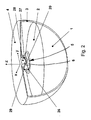
- eine schematische Darstellung der bei dem erfindungsgemäßen Ausführungsbeispiel ver- wendeten Drehlagerung mit Verdrehsicherung und doppelter Zylinder-Prismaführung.
- Der in
Fig. 1 dargestellte Antrieb entsprechend der Erfindung weist ein schalenförmiges Untergehäuse 1 und ein mit dem Untergehäuse 1 beispielsweise über Rast- und/oder Clipverbindungen verbundenes Obergehäuse auf, das das Untergehäuse deckelartig abschließt. In dem so gebildeten Gehäuse 12 sind Antriebselemente untergebracht, wie z.B. Elektromotoren, Getriebeschnecken und Zahnräder. - Das schalenförmige Gehäuse 12 aus Untergehäuse 1 und Obergehäuse 2 wird von einer ringförmigen Antriebsschale 3 übergriffen, die mit einer Trägerplatte 4 verbunden ist, wobei die Verbindungen wiederum Rast- und Schnappverbindungen sein können. Unter ringförmiger Antriebsschale wird verstanden, dass das Untergehäuse 1 nur bereichsweise übergriffen wird, wie aus
Fig. 1 gut zu erkennen ist. Die Innenfläche der Antriebsschale gleitet auf der Außenfläche des schalenförmigen Untergehäuses, wodurch die Trägerplatte 4 geschwenkt wird. An der Träger- oder Adapterplatte 4 wird im bevorzugten Ausführungsbeispiel ein Spiegelelement eines Rückblickspiegels für Kraftfahrzeuge befestigt. Auf der Innenseite der Antriebsschale 3 ist im dargestellten Ausführungsbeispiele eine Verzahnung 13 angedeutet, die mit einem nicht dargestellten Antriebszahnrad in Eingriff steht, das das Untergehäuses durchgreift und über Getriebeelemente von einem Elektromotor (nicht dargestellt) angetrieben wird. Eine weitere Verzahnung 13 ist etwa 90° zu der dargestellten Verzahnung 13 angeordnet und steht mit einem nicht dargestellten weiteren Antriebszahnrad in Verbindung. Dadurch lässt sich die Trägerplatte 4 in alle Richtungen schwenken. - In dem Obergehäuse 2 ist um eine Mittelachse 14 des Antriebs herum eine Vertiefung 15 vorgesehen, in die ein Ausgleichselement 6 eingesetzt ist. Das Ausgleichselement 6 umfasst ein plattenförmiges Teil 16, an das zwei in die Vertiefung 15 hineinragende Stifte 17 und zwei Führungen 18 angeformt sind. Das plattenförmige Oberteil 16 und auch die Vertiefung 15 haben einen viereckigen Umriss. Die Vertiefung 15 setzt sich in angeformten Hohlansätzen 19 fort, die zur Aufnahme der Stifte 17 und der Führungen 18 dienen. Zwischen dem Boden dieser Hohlansätze 19 und dem plattenförmigen Oberteil 16 des Ausgleichselements 6 sind um die Stifte 17 herum Spiralfedern 7 unter Vorspannung eingesetzt. Diese Federn 7 drücken somit das Ausgleichselement 6 in der
Fig. 1 nach oben. - Die Drehachse des Antriebs, beispielsweise eines Spiegelverstellantriebs, wird durch die Kugelfläche an der Antriebsschale 3 und durch die Kugelfläche am Untergehäuse bestimmt. Dabei schwenkt die Antriebsschale 3 mit Trägerplatte 4 um eine Lagerung 5 mit Verdrehsicherung, die mit Hilfe von
Fig. 2 näher erläutert wird. In dieserFig. 2 sind das Untergehäuse 1 und das Obergehäuse 2 sowie die Antriebsschale 3 mit der Trägerplatte 4 schematisch dargestellt und dienen in dieser Form der Erläuterung der Lagerung 5. Ein Koordinatensystem ist in bekannter Weise mit x, y und z bezeichnet. Das Ausgleichselement 6, von dem hier schematisch ein Teil des Oberteils zu sehen ist, weist eine Prismaführung 26 aus zwei schrägen Flächen auf, auf denen ein Verdrehsicherungselement oder Zwischenelement 20 aufliegt. Dieses Zwischenelement 20 ist auf der dem Ausgleichselement 6 zugewandten Seite mit einer Teilzylinderfläche 29 versehen, die auch in einzelnen Kufen, wie inFig. 1 dargestellt, ausgebildet sein kann. An der Trägerplatte 4 ist gleichfalls ein Teilzylinder 28 angeformt, wie er im Schnitt auch inFig. 1 zu erkennen ist. Dieser Teilzylinder wird von dem Zwischenelement 20 aufgenommen, das auf der dem Teilzylinder 28 zugewandten Seite eine Prismaführung 27 bestehend aus zwei Schrägen aufweist. Aufgrund dieser Anordnung der Lagerung können bei fertigungsbedingten Mittigkeitsfehlern, d.h. bei einer Nichtzentrizität, das Zwischenelement eine lineare Bewegung in y-Richtung vornehmen und der Zylinder 28 in der Prismenführung 27 eine lineare Bewegung in x-Richtung ausführen. Auf diese Weise findet ein Toleranzausgleich statt. Durch die doppelte Zylinder-Prismaführung 26, 27, 28, 29 findet beim Schwenken der Antriebsschale 3 und der Trägerplatte 4 um die x-Achse und die y-Achse jeweils eine Linienberührung zwischen den schrägen Flächen der Prismenführungen 26 und 27 und den zugeordneten Teilzylindern 28 und 29 statt. - Wie in
Fig. 1 zu erkennen ist, wird der Antrieb an einer feststehenden Struktur, beispielsweise einem mit dem Kraftfahrzeug verbundenen Teil eines Spiegelträgerteils, befestigt, wobei eine Steckbuchse 21 des Antriebs mit einem entsprechenden Stecker einer elektrischen Leitung verbunden wird. Üblicherweise wird der Antrieb mittels einer Befestigungsschraube 11 mit der feststehenden Struktur 10 verschraubt, derart, dass das Untergehäuse mit Auflagepunkten 9 sich an der feststehenden Struktur 10 abstützt. Um eine sichere Abstützung des Antriebs über die gesamte Lebensdauer zu erreichen, ist, wie ausFig. 1 zu erkennen ist, eine Hülse 8 in dem Gehäuse 12 um die Mittelachse 14 herum aufgenommen. Die Hülse 8 weist an einem Ende einen tellerfederartigen Ansatz 22 auf, der sich am Boden 23 des Untergehäuses 1 abstützt, wobei dieser Boden eine nach innen gezogene Erhöhung 24 aufweist, die in den tellerfederartigen Ansatz 22 eingreift und die um eine Öffnung im Boden 23 für den Durchgriff der Befestigungsschraube 11 angeordnet ist. Eine Verlängerung 25 der hohlzylindrischen Vertiefung 19 drückt dabei von oben (entsprechendFig. 1 ) auf den Teller 22. Die Hülse 8 durchgreift die Teile der Lagerung 5 und ragt in eine Vertiefung der Trägerplatte 4 hinein, die ausgebildet ist, um das Schwenken der Trägerplatte 4 zusammen mit der Antriebsschale 3 zuzulassen. Zum Einschrauben der Befestigungsschraube 11 in die feststehende Struktur 10 wird die Schraube 11 durch die Hülse 8 geführt und beim Festziehen wird der tellerförmige Ansatz gegen den Boden 23 und die Erhöhung 24 gedrückt, so dass im Wesentlichen die Luft zwischen diesen Teilen eliminiert und der Boden unter Spannung gehalten wird. Dadurch wird die Vorspannkraft auf die Auflagepunkte 9 verteilt, so dass die Schraube sich auch über die Lebensdauer nicht lockern kann und der Antrieb fest auf der feststehenden Struktur sitzt. - Wenn im Laufe der Lebensdauer des Antriebs der Kunststoff einer Relaxation unterliegt, durch die ein Spiel zwischen dem Untergehäuse 1, d.h. zwischen seiner äußeren Kugelfläche und der Antriebsschale 3, d.h. ihrer inneren Kugelfläche, auftreten könnte, drücken die Spiralfedern 7 das Ausgleichselement 6 in der
Fig. 1 nach oben, wodurch auch die Teile der Lagerung 5 und damit die Trägerplatte 4 zusammen mit der Antriebsschale nach oben gedrückt werden, so dass die Antriebsschale 3 immer an dem Untergehäuse 1 anliegt und sich eine definierte Reibung zwischen Untergehäuse 1 und Antriebsschale 3 ergibt. Durch die axiale Federkraft der Spiralfedern 7 und dem Ausgleichselement 6 wird somit die Antriebsschale 3 gleichmäßig über den gesamten Umfang gegen das untere Gehäuse 1 spielfrei gehalten.
Claims (14)
- Antrieb für ein zu verstellendes Bauteil, insbesondere für einen verstellbaren Kraftfahrzeugspiegel, mit einem an einer feststehenden Struktur (10) befestigbaren Gehäuse (12) zur Aufnahme von Antriebselementen und mit einem das Gehäuse (12) zumindest teilweise umgreifenden Element (3), das mit einem Träger (4) für das Bauteil verbunden ist, wobei das umgreifende Element (3) mit dem Träger (4) relativ zu dem Gehäuse (12) schwenkbar angeordnet ist und,
dadurch gekennzeichnet,
dass Mittel zur elastischen Vorspannung zwischen Gehäuse (12) und umgreifendem Element (3) vorgesehen sind, wobei die Mittel (6, 7) zur elastischen Vorspannung ein um eine Mittelachse (14) des Gehäuses (12) herum angeordnetes Ausgleichselement (6) aufweisen, wobei das Ausgleichselement (6) unter der Wirkung einer Federkraft axial zur Ausübung eines Drucks auf den Träger (4) und damit auf das das Gehäuse (12) umgreifende Element (3) bewegbar ist, wobei zwischen Ausgleichselement (6) und Gehäuse (12) mindestens zwei axial zur Mittelachse des Gehäuses wirkende, symmetrisch zur Mittelachse angeordnete Federn (7) angeordnet sind. - Antrieb nach Anspruch 1, dadurch gekennzeichnet, dass das Gehäuse aus einem schalenförmigen Untergehäuse (1) und einem deckelartigen Obergehäuse (2) besteht, wobei das Ausgleichselement (6) in einer mittigen Vertiefung (15) des Obergehäuses (2) aufgenommen ist.
- Antrieb nach einem der Ansprüche 1 oder 2, dadurch gekennzeichnet, dass dem Ausgleichselement (6) Mittel zu seiner Zentrierung in Bezug auf das Gehäuse (12) zugeordnet sind.
- Antrieb nach einem der Ansprüche 1 bis 3, dadurch gekennzeichnet, dass in dem Gehäuse (12) um die Mittelachse (14) herum eine stiftartige Hülse (8) zur Aufnahme einer Befestigungsschraube angeordnet ist.
- Antrieb nach Anspruch 3 oder Anspruch 4, dadurch gekennzeichnet, dass das Ausgleichselement (6) eine Öffnung für den Durchgriff der stiftartigen Hülse (8) aufweist.
- Antrieb nach einem der Ansprüche 1 bis 5, dadurch gekennzeichnet, dass die mindestens zwei Federn (7) als Spiralfedern ausgebildet sind.
- Antrieb nach einem der Ansprüche 1 bis 6, dadurch gekennzeichnet, dass das Ausgleichselement (6) plattenartig ausgebildet ist.
- Antrieb nach einem der Ansprüche 1 bis 7, dadurch gekennzeichnet, dass das Ausgleichselement (6) eine Führung (26), vorzugsweise eine Prismaführung aus zwei prismaähnlichen Flächen oder eine gekrümmte Fläche, vorzugsweise eine Teilzylinderfläche aufweist.
- Antrieb nach Anspruch 8, dadurch gekennzeichnet, dass der Träger (4) als Trägerplatte, vorzugsweise zur Befestigung eines Spiegels ausgebildet ist und dass an die Trägerplatte mittig ein Teilzylinder (28) angeformt ist.
- Antrieb nach Anspruch 8 und Anspruch 9, dadurch gekennzeichnet, dass zwischen Teilzylinder (28) der Trägerplatte (4) und Ausgleichselement (6) ein Verdrehsicherungselement (20) angeordnet ist, das eine dem Teilzylinder (28) zugewandte Führung (27) aus prismaähnlichen Flächen oder gekrümmten Lagerflächen und eine dem Ausgleichselement (6) zugewandte teilzylinderförmige Gleitfläche (29) aufweist.
- Antrieb nach Anspruch 10, dadurch gekennzeichnet, dass Ausgleichselement (6), Verdrehsicherungselement (20) und Teilzylinder (28) der Trägerplatte (4) ein Drehlager für die Trägerplatte (4) und das übergreifende Element (3) mit doppelter Zylinder-Prismaführung bilden.
- Antrieb nach einem der Ansprüche 4 bis 11, dadurch gekennzeichnet, dass die stiftartige Hülse (8) einen tellerfederartigen Ansatz (22) aufweist, der sich gegen das Gehäuse (12) abstützt.
- Antrieb nach Anspruch 12, dadurch gekennzeichnet, dass der tellerfederartige Ansatz (22) sich am Boden (23) des Untergehäuses (1) abstützt und mindestens ein am Obergehäuse (2) angeformter Ansatz (24) einen Anschlag zum Niederhalten des tellerartigen Ansatzes (22) bildet.
- Antrieb nach einem der vorangehenden Ansprüche, dadurch gekennzeichnet, dass an dem Ausgleichselement (6) Stifte (17) für die Zentrierung der Federn (7) angeordnet sind.
Priority Applications (6)
| Application Number | Priority Date | Filing Date | Title |
|---|---|---|---|
| EP09075020A EP2208642B1 (de) | 2009-01-14 | 2009-01-14 | Antrieb für ein zu verstellendes Bauteil |
| ES09075020T ES2374611T3 (es) | 2009-01-14 | 2009-01-14 | Accionamiento para un componente que se ha de ajustar. |
| AT09075020T ATE528170T1 (de) | 2009-01-14 | 2009-01-14 | Antrieb für ein zu verstellendes bauteil |
| JP2011545692A JP2012515108A (ja) | 2009-01-14 | 2010-01-13 | 調整されるべき構成要素のための駆動装置 |
| US13/144,420 US8801203B2 (en) | 2009-01-14 | 2010-01-13 | Drive for a component to be adjusted |
| PCT/EP2010/000238 WO2010081732A1 (de) | 2009-01-14 | 2010-01-13 | Antrieb für ein zu verstellendes bauteil |
Applications Claiming Priority (1)
| Application Number | Priority Date | Filing Date | Title |
|---|---|---|---|
| EP09075020A EP2208642B1 (de) | 2009-01-14 | 2009-01-14 | Antrieb für ein zu verstellendes Bauteil |
Publications (2)
| Publication Number | Publication Date |
|---|---|
| EP2208642A1 EP2208642A1 (de) | 2010-07-21 |
| EP2208642B1 true EP2208642B1 (de) | 2011-10-12 |
Family
ID=40601179
Family Applications (1)
| Application Number | Title | Priority Date | Filing Date |
|---|---|---|---|
| EP09075020A Active EP2208642B1 (de) | 2009-01-14 | 2009-01-14 | Antrieb für ein zu verstellendes Bauteil |
Country Status (6)
| Country | Link |
|---|---|
| US (1) | US8801203B2 (de) |
| EP (1) | EP2208642B1 (de) |
| JP (1) | JP2012515108A (de) |
| AT (1) | ATE528170T1 (de) |
| ES (1) | ES2374611T3 (de) |
| WO (1) | WO2010081732A1 (de) |
Families Citing this family (3)
| Publication number | Priority date | Publication date | Assignee | Title |
|---|---|---|---|---|
| JP2016002878A (ja) * | 2014-06-17 | 2016-01-12 | 株式会社東海理化電機製作所 | 車両用ミラー装置 |
| NL2016120B1 (nl) * | 2016-01-19 | 2017-07-25 | MCI (Mirror Controls International) Netherlands B V | Bevestigingsconstructie voor bevestiging van een verstelinstrument voor een buitenzichtelement, zoals een buitenspiegel, camera en/of display, aan een draagframe van een buitenzichteenheid van een motorvoertuig, alsmede buitenzichteenheid |
| NL2025272B1 (nl) * | 2020-04-03 | 2021-10-25 | Mci Mirror Controls Int Netherlands B V | Verstelinstrument voor een buitenzichteenheid van een motorvoertuig |
Family Cites Families (14)
| Publication number | Priority date | Publication date | Assignee | Title |
|---|---|---|---|---|
| US4915493A (en) * | 1989-01-04 | 1990-04-10 | Magna International Inc. | Automotive rear view mirror assembly |
| US4981279A (en) * | 1989-11-07 | 1991-01-01 | Sheller-Globe Corporation | Adjustable rear view mirror |
| US5621577A (en) * | 1990-03-29 | 1997-04-15 | Mekra Rangau Plastics Gmbh & Co. Kg | External rear-view mirror for commerical vehicles |
| AU676322B2 (en) * | 1993-05-12 | 1997-03-06 | United Technologies Automotive, Inc. | Mirror assembly for the exterior of an automotive vehicle having a hand set adjustment mechanism |
| US5363246A (en) * | 1993-05-12 | 1994-11-08 | United Technologies Automotive, Inc. | Power pack for an automotive exterior mirror assembly |
| AT405501B (de) | 1997-01-17 | 1999-09-27 | Magna Reflex Holding Gmbh | Verstellbarer rückspiegel, insbesondere aussenspiegel, für ein kraftfahrzeug |
| BR9702665A (pt) * | 1997-07-28 | 1999-10-05 | Metagal Ind Stria E Comercio L | Articulação multiuso para espelhos retrovisores externos |
| ES2190868B1 (es) * | 2001-03-30 | 2005-02-01 | Fico Mirrors, S.A. | Mecanismo de regulacion manual para retrovisores exteriores de vehiculos automoviles. |
| DE602004020151D1 (de) * | 2003-07-10 | 2009-05-07 | Ichikoh Industries Ltd | Vorrichtung zur Neigungsverstellung eines Aussenspiegels |
| JP4695601B2 (ja) * | 2004-10-08 | 2011-06-08 | 株式会社村上開明堂 | 鏡面角度調整装置 |
| WO2006040803A1 (ja) * | 2004-10-08 | 2006-04-20 | Murakami Corporation | 鏡面角度調整装置 |
| DE602004029102D1 (de) * | 2004-10-08 | 2010-10-21 | Murakami Corp | Spiegelwinkeleinstellvorrichtung |
| NL1027557C2 (nl) | 2004-11-22 | 2006-05-23 | Eaton Automotive Bv | Spiegelverstelmechanisme, in het bijzonder voor een buitenspiegel voor een motorvoertuig. |
| JP5100170B2 (ja) * | 2007-03-27 | 2012-12-19 | 株式会社ホンダロック | 車両用ドアミラー |
-
2009
- 2009-01-14 AT AT09075020T patent/ATE528170T1/de active
- 2009-01-14 ES ES09075020T patent/ES2374611T3/es active Active
- 2009-01-14 EP EP09075020A patent/EP2208642B1/de active Active
-
2010
- 2010-01-13 JP JP2011545692A patent/JP2012515108A/ja active Pending
- 2010-01-13 US US13/144,420 patent/US8801203B2/en active Active
- 2010-01-13 WO PCT/EP2010/000238 patent/WO2010081732A1/de not_active Ceased
Also Published As
| Publication number | Publication date |
|---|---|
| JP2012515108A (ja) | 2012-07-05 |
| US20120008223A1 (en) | 2012-01-12 |
| ATE528170T1 (de) | 2011-10-15 |
| ES2374611T3 (es) | 2012-02-20 |
| EP2208642A1 (de) | 2010-07-21 |
| US8801203B2 (en) | 2014-08-12 |
| WO2010081732A1 (de) | 2010-07-22 |
Similar Documents
| Publication | Publication Date | Title |
|---|---|---|
| DE102017200213B4 (de) | Motorisch verstellbare Lenksäule für ein Kraftfahrzeug | |
| EP1057239A1 (de) | Elektrischer getriebemotor für fahrzeugaggregate | |
| EP2726323A1 (de) | Stelleinheit für kraftfahrzeugtechnische anwendungen | |
| DE202010002223U1 (de) | Verstellvorrichtung mit einer Umlenkbaugruppe | |
| EP2208641B1 (de) | Antrieb für ein zu verstellendes Bauteil | |
| WO2000031856A1 (de) | Antriebsvorrichtung, insbesondere für eine scheibenwischanlage eines kraftfahrzeuges | |
| EP2198490B1 (de) | Bürstenanordnung und elektrische maschine, insbesondere elektrisches hausgerät | |
| EP2032401A1 (de) | Scheibenwischvorrichtung, insbesondere für ein kraftfahrzeug | |
| DE19744199A1 (de) | Gleitelement | |
| DE202011051957U1 (de) | Türfeststeller für Kraftfahrzeuge | |
| EP2208642A1 (de) | Antrieb für ein zu verstellendes Bauteil | |
| EP1744082B1 (de) | Stellantrieb, insbesondere für ein Kraftfahrzeug | |
| DE102013202762B4 (de) | Ventilhaube | |
| EP1841972A1 (de) | Verliergesicherte befestigungsschraube | |
| EP1869333B1 (de) | Lagerbuchse | |
| EP2208640A1 (de) | Antrieb für ein zu verstellendes Bauteil | |
| EP2167354A1 (de) | Befestigungsanordnung | |
| DE102018124143A1 (de) | Lagervorrichtung, Verstellvorrichtung, verstellbare Lenksäule, Verfahren zum Herstellen einer Verstellvorrichtung | |
| EP1833699B1 (de) | Haltevorrichtung | |
| EP1741521B1 (de) | Handwerkzeuggerät mit Schutzhaube | |
| DE102006043186B4 (de) | Gelenkeinrichtung | |
| EP1627795B1 (de) | Befestigung eines Lenksäulenmoduls | |
| DE10054537A1 (de) | Bürstenanordnung für Elektromotoren | |
| DE102023134170B4 (de) | Lenkgetriebe | |
| EP2102041A1 (de) | Lagersitzanordnung zur axialen und radialen fixierung |
Legal Events
| Date | Code | Title | Description |
|---|---|---|---|
| PUAI | Public reference made under article 153(3) epc to a published international application that has entered the european phase |
Free format text: ORIGINAL CODE: 0009012 |
|
| AK | Designated contracting states |
Kind code of ref document: A1 Designated state(s): AT BE BG CH CY CZ DE DK EE ES FI FR GB GR HR HU IE IS IT LI LT LU LV MC MK MT NL NO PL PT RO SE SI SK TR |
|
| AX | Request for extension of the european patent |
Extension state: AL BA RS |
|
| 17P | Request for examination filed |
Effective date: 20110121 |
|
| AKX | Designation fees paid |
Designated state(s): AT BE BG CH CY CZ DE DK EE ES FI FR GB GR HR HU IE IS IT LI LT LU LV MC MK MT NL NO PL PT RO SE SI SK TR |
|
| GRAP | Despatch of communication of intention to grant a patent |
Free format text: ORIGINAL CODE: EPIDOSNIGR1 |
|
| RIC1 | Information provided on ipc code assigned before grant |
Ipc: B60R 1/066 20060101ALI20110323BHEP Ipc: B60R 1/072 20060101AFI20110323BHEP |
|
| GRAS | Grant fee paid |
Free format text: ORIGINAL CODE: EPIDOSNIGR3 |
|
| GRAA | (expected) grant |
Free format text: ORIGINAL CODE: 0009210 |
|
| AK | Designated contracting states |
Kind code of ref document: B1 Designated state(s): AT BE BG CH CY CZ DE DK EE ES FI FR GB GR HR HU IE IS IT LI LT LU LV MC MK MT NL NO PL PT RO SE SI SK TR |
|
| REG | Reference to a national code |
Ref country code: GB Ref legal event code: FG4D Free format text: NOT ENGLISH |
|
| REG | Reference to a national code |
Ref country code: CH Ref legal event code: EP |
|
| REG | Reference to a national code |
Ref country code: IE Ref legal event code: FG4D |
|
| REG | Reference to a national code |
Ref country code: DE Ref legal event code: R096 Ref document number: 502009001555 Country of ref document: DE Effective date: 20111208 |
|
| REG | Reference to a national code |
Ref country code: NL Ref legal event code: VDEP Effective date: 20111012 |
|
| REG | Reference to a national code |
Ref country code: ES Ref legal event code: FG2A Ref document number: 2374611 Country of ref document: ES Kind code of ref document: T3 Effective date: 20120220 |
|
| LTIE | Lt: invalidation of european patent or patent extension |
Effective date: 20111012 |
|
| PG25 | Lapsed in a contracting state [announced via postgrant information from national office to epo] |
Ref country code: NO Free format text: LAPSE BECAUSE OF FAILURE TO SUBMIT A TRANSLATION OF THE DESCRIPTION OR TO PAY THE FEE WITHIN THE PRESCRIBED TIME-LIMIT Effective date: 20120112 Ref country code: IS Free format text: LAPSE BECAUSE OF FAILURE TO SUBMIT A TRANSLATION OF THE DESCRIPTION OR TO PAY THE FEE WITHIN THE PRESCRIBED TIME-LIMIT Effective date: 20120212 Ref country code: LT Free format text: LAPSE BECAUSE OF FAILURE TO SUBMIT A TRANSLATION OF THE DESCRIPTION OR TO PAY THE FEE WITHIN THE PRESCRIBED TIME-LIMIT Effective date: 20111012 |
|
| REG | Reference to a national code |
Ref country code: IE Ref legal event code: FD4D |
|
| PG25 | Lapsed in a contracting state [announced via postgrant information from national office to epo] |
Ref country code: GR Free format text: LAPSE BECAUSE OF FAILURE TO SUBMIT A TRANSLATION OF THE DESCRIPTION OR TO PAY THE FEE WITHIN THE PRESCRIBED TIME-LIMIT Effective date: 20120113 Ref country code: PT Free format text: LAPSE BECAUSE OF FAILURE TO SUBMIT A TRANSLATION OF THE DESCRIPTION OR TO PAY THE FEE WITHIN THE PRESCRIBED TIME-LIMIT Effective date: 20120213 Ref country code: NL Free format text: LAPSE BECAUSE OF FAILURE TO SUBMIT A TRANSLATION OF THE DESCRIPTION OR TO PAY THE FEE WITHIN THE PRESCRIBED TIME-LIMIT Effective date: 20111012 Ref country code: LV Free format text: LAPSE BECAUSE OF FAILURE TO SUBMIT A TRANSLATION OF THE DESCRIPTION OR TO PAY THE FEE WITHIN THE PRESCRIBED TIME-LIMIT Effective date: 20111012 Ref country code: HR Free format text: LAPSE BECAUSE OF FAILURE TO SUBMIT A TRANSLATION OF THE DESCRIPTION OR TO PAY THE FEE WITHIN THE PRESCRIBED TIME-LIMIT Effective date: 20111012 Ref country code: SI Free format text: LAPSE BECAUSE OF FAILURE TO SUBMIT A TRANSLATION OF THE DESCRIPTION OR TO PAY THE FEE WITHIN THE PRESCRIBED TIME-LIMIT Effective date: 20111012 Ref country code: SE Free format text: LAPSE BECAUSE OF FAILURE TO SUBMIT A TRANSLATION OF THE DESCRIPTION OR TO PAY THE FEE WITHIN THE PRESCRIBED TIME-LIMIT Effective date: 20111012 |
|
| PG25 | Lapsed in a contracting state [announced via postgrant information from national office to epo] |
Ref country code: CY Free format text: LAPSE BECAUSE OF FAILURE TO SUBMIT A TRANSLATION OF THE DESCRIPTION OR TO PAY THE FEE WITHIN THE PRESCRIBED TIME-LIMIT Effective date: 20111012 |
|
| BERE | Be: lapsed |
Owner name: MAGNA AUTECA AG Effective date: 20120131 |
|
| PG25 | Lapsed in a contracting state [announced via postgrant information from national office to epo] |
Ref country code: SK Free format text: LAPSE BECAUSE OF FAILURE TO SUBMIT A TRANSLATION OF THE DESCRIPTION OR TO PAY THE FEE WITHIN THE PRESCRIBED TIME-LIMIT Effective date: 20111012 Ref country code: IE Free format text: LAPSE BECAUSE OF FAILURE TO SUBMIT A TRANSLATION OF THE DESCRIPTION OR TO PAY THE FEE WITHIN THE PRESCRIBED TIME-LIMIT Effective date: 20111012 Ref country code: CZ Free format text: LAPSE BECAUSE OF FAILURE TO SUBMIT A TRANSLATION OF THE DESCRIPTION OR TO PAY THE FEE WITHIN THE PRESCRIBED TIME-LIMIT Effective date: 20111012 Ref country code: DK Free format text: LAPSE BECAUSE OF FAILURE TO SUBMIT A TRANSLATION OF THE DESCRIPTION OR TO PAY THE FEE WITHIN THE PRESCRIBED TIME-LIMIT Effective date: 20111012 Ref country code: EE Free format text: LAPSE BECAUSE OF FAILURE TO SUBMIT A TRANSLATION OF THE DESCRIPTION OR TO PAY THE FEE WITHIN THE PRESCRIBED TIME-LIMIT Effective date: 20111012 Ref country code: BG Free format text: LAPSE BECAUSE OF FAILURE TO SUBMIT A TRANSLATION OF THE DESCRIPTION OR TO PAY THE FEE WITHIN THE PRESCRIBED TIME-LIMIT Effective date: 20120112 |
|
| PLBE | No opposition filed within time limit |
Free format text: ORIGINAL CODE: 0009261 |
|
| STAA | Information on the status of an ep patent application or granted ep patent |
Free format text: STATUS: NO OPPOSITION FILED WITHIN TIME LIMIT |
|
| PG25 | Lapsed in a contracting state [announced via postgrant information from national office to epo] |
Ref country code: PL Free format text: LAPSE BECAUSE OF FAILURE TO SUBMIT A TRANSLATION OF THE DESCRIPTION OR TO PAY THE FEE WITHIN THE PRESCRIBED TIME-LIMIT Effective date: 20111012 Ref country code: RO Free format text: LAPSE BECAUSE OF FAILURE TO SUBMIT A TRANSLATION OF THE DESCRIPTION OR TO PAY THE FEE WITHIN THE PRESCRIBED TIME-LIMIT Effective date: 20111012 Ref country code: MC Free format text: LAPSE BECAUSE OF NON-PAYMENT OF DUE FEES Effective date: 20120131 |
|
| 26N | No opposition filed |
Effective date: 20120713 |
|
| REG | Reference to a national code |
Ref country code: DE Ref legal event code: R097 Ref document number: 502009001555 Country of ref document: DE Effective date: 20120713 |
|
| PG25 | Lapsed in a contracting state [announced via postgrant information from national office to epo] |
Ref country code: BE Free format text: LAPSE BECAUSE OF NON-PAYMENT OF DUE FEES Effective date: 20120131 |
|
| PG25 | Lapsed in a contracting state [announced via postgrant information from national office to epo] |
Ref country code: MK Free format text: LAPSE BECAUSE OF FAILURE TO SUBMIT A TRANSLATION OF THE DESCRIPTION OR TO PAY THE FEE WITHIN THE PRESCRIBED TIME-LIMIT Effective date: 20111012 |
|
| REG | Reference to a national code |
Ref country code: DE Ref legal event code: R082 Ref document number: 502009001555 Country of ref document: DE Representative=s name: RAUSCH, GABRIELE, DIPL.-PHYS. DR.RER.NAT., DE Ref country code: DE Ref legal event code: R082 Ref document number: 502009001555 Country of ref document: DE Representative=s name: , |
|
| PG25 | Lapsed in a contracting state [announced via postgrant information from national office to epo] |
Ref country code: FI Free format text: LAPSE BECAUSE OF FAILURE TO SUBMIT A TRANSLATION OF THE DESCRIPTION OR TO PAY THE FEE WITHIN THE PRESCRIBED TIME-LIMIT Effective date: 20111012 |
|
| PG25 | Lapsed in a contracting state [announced via postgrant information from national office to epo] |
Ref country code: MT Free format text: LAPSE BECAUSE OF FAILURE TO SUBMIT A TRANSLATION OF THE DESCRIPTION OR TO PAY THE FEE WITHIN THE PRESCRIBED TIME-LIMIT Effective date: 20111012 |
|
| REG | Reference to a national code |
Ref country code: CH Ref legal event code: PL |
|
| PG25 | Lapsed in a contracting state [announced via postgrant information from national office to epo] |
Ref country code: CH Free format text: LAPSE BECAUSE OF NON-PAYMENT OF DUE FEES Effective date: 20130131 Ref country code: LI Free format text: LAPSE BECAUSE OF NON-PAYMENT OF DUE FEES Effective date: 20130131 |
|
| PG25 | Lapsed in a contracting state [announced via postgrant information from national office to epo] |
Ref country code: TR Free format text: LAPSE BECAUSE OF FAILURE TO SUBMIT A TRANSLATION OF THE DESCRIPTION OR TO PAY THE FEE WITHIN THE PRESCRIBED TIME-LIMIT Effective date: 20111012 |
|
| PG25 | Lapsed in a contracting state [announced via postgrant information from national office to epo] |
Ref country code: LU Free format text: LAPSE BECAUSE OF NON-PAYMENT OF DUE FEES Effective date: 20120114 |
|
| PG25 | Lapsed in a contracting state [announced via postgrant information from national office to epo] |
Ref country code: HU Free format text: LAPSE BECAUSE OF FAILURE TO SUBMIT A TRANSLATION OF THE DESCRIPTION OR TO PAY THE FEE WITHIN THE PRESCRIBED TIME-LIMIT Effective date: 20090114 |
|
| REG | Reference to a national code |
Ref country code: AT Ref legal event code: MM01 Ref document number: 528170 Country of ref document: AT Kind code of ref document: T Effective date: 20140114 |
|
| PG25 | Lapsed in a contracting state [announced via postgrant information from national office to epo] |
Ref country code: AT Free format text: LAPSE BECAUSE OF NON-PAYMENT OF DUE FEES Effective date: 20140114 |
|
| REG | Reference to a national code |
Ref country code: FR Ref legal event code: PLFP Year of fee payment: 8 |
|
| REG | Reference to a national code |
Ref country code: DE Ref legal event code: R082 Ref document number: 502009001555 Country of ref document: DE Representative=s name: RAUSCH, GABRIELE, DIPL.-PHYS. DR.RER.NAT., DE Ref country code: DE Ref legal event code: R081 Ref document number: 502009001555 Country of ref document: DE Owner name: MAGNA AUTECA GMBH, AT Free format text: FORMER OWNER: MAGNA AUTECA AG, KROTTENDORF, AT |
|
| REG | Reference to a national code |
Ref country code: FR Ref legal event code: PLFP Year of fee payment: 9 |
|
| REG | Reference to a national code |
Ref country code: FR Ref legal event code: PLFP Year of fee payment: 10 |
|
| REG | Reference to a national code |
Ref country code: DE Ref legal event code: R082 Ref document number: 502009001555 Country of ref document: DE Representative=s name: EULER, MATTHIAS, DR., DE |
|
| PGFP | Annual fee paid to national office [announced via postgrant information from national office to epo] |
Ref country code: GB Payment date: 20260123 Year of fee payment: 18 |
|
| PGFP | Annual fee paid to national office [announced via postgrant information from national office to epo] |
Ref country code: ES Payment date: 20260227 Year of fee payment: 18 |
|
| PGFP | Annual fee paid to national office [announced via postgrant information from national office to epo] |
Ref country code: DE Payment date: 20260121 Year of fee payment: 18 |
|
| PGFP | Annual fee paid to national office [announced via postgrant information from national office to epo] |
Ref country code: IT Payment date: 20260126 Year of fee payment: 18 |
|
| PGFP | Annual fee paid to national office [announced via postgrant information from national office to epo] |
Ref country code: FR Payment date: 20260123 Year of fee payment: 18 |