EP2206923B1 - Rotor für eine innenzahnradpumpe und innenzahnradpumpe mit dem rotor - Google Patents
Rotor für eine innenzahnradpumpe und innenzahnradpumpe mit dem rotor Download PDFInfo
- Publication number
- EP2206923B1 EP2206923B1 EP09804956.2A EP09804956A EP2206923B1 EP 2206923 B1 EP2206923 B1 EP 2206923B1 EP 09804956 A EP09804956 A EP 09804956A EP 2206923 B1 EP2206923 B1 EP 2206923B1
- Authority
- EP
- European Patent Office
- Prior art keywords
- rotor
- inner rotor
- circle
- addendum
- formation
- Prior art date
- Legal status (The legal status is an assumption and is not a legal conclusion. Google has not performed a legal analysis and makes no representation as to the accuracy of the status listed.)
- Active
Links
- 230000015572 biosynthetic process Effects 0.000 claims description 165
- 238000000034 method Methods 0.000 claims description 33
- 230000014509 gene expression Effects 0.000 claims description 6
- 239000012530 fluid Substances 0.000 claims description 2
- 238000005096 rolling process Methods 0.000 description 28
- 230000001965 increasing effect Effects 0.000 description 9
- 230000000052 comparative effect Effects 0.000 description 6
- 238000012360 testing method Methods 0.000 description 6
- 230000007423 decrease Effects 0.000 description 5
- 239000003921 oil Substances 0.000 description 5
- 230000010349 pulsation Effects 0.000 description 4
- 230000003247 decreasing effect Effects 0.000 description 3
- XEEYBQQBJWHFJM-UHFFFAOYSA-N Iron Chemical compound [Fe] XEEYBQQBJWHFJM-UHFFFAOYSA-N 0.000 description 2
- 230000005540 biological transmission Effects 0.000 description 2
- 230000002708 enhancing effect Effects 0.000 description 2
- 238000005461 lubrication Methods 0.000 description 2
- 239000000956 alloy Substances 0.000 description 1
- 229910045601 alloy Inorganic materials 0.000 description 1
- 238000013461 design Methods 0.000 description 1
- 238000006073 displacement reaction Methods 0.000 description 1
- 230000000694 effects Effects 0.000 description 1
- 238000011156 evaluation Methods 0.000 description 1
- 239000012208 gear oil Substances 0.000 description 1
- 229910052742 iron Inorganic materials 0.000 description 1
- 238000005259 measurement Methods 0.000 description 1
- 238000005086 pumping Methods 0.000 description 1
Images


Classifications
-
- F—MECHANICAL ENGINEERING; LIGHTING; HEATING; WEAPONS; BLASTING
- F04—POSITIVE - DISPLACEMENT MACHINES FOR LIQUIDS; PUMPS FOR LIQUIDS OR ELASTIC FLUIDS
- F04C—ROTARY-PISTON, OR OSCILLATING-PISTON, POSITIVE-DISPLACEMENT MACHINES FOR LIQUIDS; ROTARY-PISTON, OR OSCILLATING-PISTON, POSITIVE-DISPLACEMENT PUMPS
- F04C2/00—Rotary-piston machines or pumps
- F04C2/08—Rotary-piston machines or pumps of intermeshing-engagement type, i.e. with engagement of co-operating members similar to that of toothed gearing
- F04C2/082—Details specially related to intermeshing engagement type machines or pumps
- F04C2/084—Toothed wheels
-
- F—MECHANICAL ENGINEERING; LIGHTING; HEATING; WEAPONS; BLASTING
- F04—POSITIVE - DISPLACEMENT MACHINES FOR LIQUIDS; PUMPS FOR LIQUIDS OR ELASTIC FLUIDS
- F04C—ROTARY-PISTON, OR OSCILLATING-PISTON, POSITIVE-DISPLACEMENT MACHINES FOR LIQUIDS; ROTARY-PISTON, OR OSCILLATING-PISTON, POSITIVE-DISPLACEMENT PUMPS
- F04C2/00—Rotary-piston machines or pumps
- F04C2/08—Rotary-piston machines or pumps of intermeshing-engagement type, i.e. with engagement of co-operating members similar to that of toothed gearing
- F04C2/10—Rotary-piston machines or pumps of intermeshing-engagement type, i.e. with engagement of co-operating members similar to that of toothed gearing of internal-axis type with the outer member having more teeth or tooth-equivalents, e.g. rollers, than the inner member
- F04C2/102—Rotary-piston machines or pumps of intermeshing-engagement type, i.e. with engagement of co-operating members similar to that of toothed gearing of internal-axis type with the outer member having more teeth or tooth-equivalents, e.g. rollers, than the inner member the two members rotating simultaneously around their respective axes
-
- Y—GENERAL TAGGING OF NEW TECHNOLOGICAL DEVELOPMENTS; GENERAL TAGGING OF CROSS-SECTIONAL TECHNOLOGIES SPANNING OVER SEVERAL SECTIONS OF THE IPC; TECHNICAL SUBJECTS COVERED BY FORMER USPC CROSS-REFERENCE ART COLLECTIONS [XRACs] AND DIGESTS
- Y10—TECHNICAL SUBJECTS COVERED BY FORMER USPC
- Y10T—TECHNICAL SUBJECTS COVERED BY FORMER US CLASSIFICATION
- Y10T74/00—Machine element or mechanism
- Y10T74/19—Gearing
- Y10T74/19949—Teeth
- Y10T74/19963—Spur
- Y10T74/19972—Spur form
Definitions
- the present invention relates to an internal gear pump rotor including in combination an inner rotor and an outer rotor whose numbers of teeth are different by one, and to an internal gear pump using the rotor. More specifically, the present invention can increase the theoretical discharge amount of the pump by allowing flexibility in setting the depth and number of teeth.
- Internal gear pumps are used, for example, as oil pumps for lubrication of a car engine and for an automatic transmission (AT).
- A automatic transmission
- inner and outer rotors whose numbers of teeth are different by one, are combined.
- the tooth profile of the rotor is formed by a trochoidal curve, see for example the Patent Document 2, or the tooth profile of the rotor is formed by a cycloidal curve, see for example the Patent Document 3.
- a tooth profile of an inner rotor is formed by a base circle, a locus of one point on the circumference of an externally rolling circle that does not slip, but rolls on the base circle while being circumscribed about the base circle, and a locus of one point on the circumference of an internally rolling circle that does not slip, but rolls on the base circle while being inscribed in the base circle.
- one base circle E, one rolling circle F, one locus circle G, and one amount of eccentricity e are set. While it is only necessary to increase the tooth depth in order to increase the discharge amount of a pump having the tooth profile, when the amount of eccentricity e between the inner rotor and an outer rotor is increased to increase the tooth depth, the tooth width becomes too small or it becomes impossible to design the tooth profile. Therefore, the amount of eccentricity e is restricted, and the tooth depth is limited. For this reason, it is difficult to meet the demand to increase the discharge amount.
- the discharge amount can be increased by increasing the number of teeth.
- the number of teeth increases, the radial dimension of the rotor increases.
- the number of teeth of the rotor is determined by the diameter of a base circle and the diameters of an externally rolling circle and an internally rolling circle which form the tooth profile by rolling on the base circle without slipping thereon. Further, since the tooth depth of the rotor is determined by the diameters of the externally rolling circle and the internally rolling circle, the discharge amount of the pump depends on the diameters of the base circle and the rolling circles. For this reason, the degree of flexibility in setting the tooth depth and the number of teeth is low, and it is difficult to meet the demand to increase the discharge amount of the pump.
- An object of the present invention is to increase the discharge amount of a pump and to suppress discharge pulsation by allowing flexibility in setting the tooth depth of a pump rotor that includes in combination an inner rotor and an outer rotor whose numbers of teeth are different by one.
- a method of forming a tooth profile of an internal gear pump rotor is defined by the wording of claim 1.
- the formation circles B and C two circles, that is, a circle whose center moves from the moving start point to the moving end point while keeping its diameter Bd or Cd fixed, and a circle whose center moves from the moving start point to the moving end point while decreasing its diameter Bd or Cd, are conceivable.
- An appropriate one of the formation circles can be selected in consideration of the required performance of the pump.
- the centers pa of the formation circles move on curves AC 1 and AC 2 where a change rate ⁇ R of the distances between the inner rotor center O I and the centers of formation circles is 0 at the moving end points Lpa and Lpb.
- the curves AC 1 and AC 2 are curves using a sine function.
- an addendum top T T is set on a straight line L 2 turned by an angle ⁇ T from the straight line L 1
- a dedendum bottom T B is set on a straight line L 3 turned by an angle ⁇ B from the straight line L 1 .
- the angle ⁇ T between the straight line L 1 and the straight line L 2 and the angle ⁇ B between the straight line L 1 and the straight line L 3 are set in consideration of, for example, the number of teeth and the ratio of setting areas of an addendum and a dedendum.
- the moving start point Spa of the center of the addendum formation circle B and the moving start point Spb of the center of the dedendum formation circle C are on the straight line L 1 . Further, the moving end points Lpa and Lpb thereof are on the straight lines L 2 and L 3 , respectively.
- an internal gear pump rotor including an inner rotor having the above-described tooth profile and the following outer rotor in combination.
- a tooth profile of the outer rotor is determined by the following steps:
- the inner rotor makes a 1/n rotation.
- the envelope thus determined serves as the tooth profile.
- the tip clearance is defined as follows:
- the outer rotor is set in a state in which the center of the outer rotor is at one point on the Y-axis at a distance, which is equal to the amount of eccentricity e, from the origin and an addendum top of the outer rotor meets the addendum top of the inner rotor in the negative area on the Y-axis.
- the outer rotor center is moved on the Y-axis away from the inner rotor center until the tooth profile of the inner rotor and the tooth profile of the outer rotor come into contact with each other.
- a clearance formed between the addendum top of the inner rotor on the Y-axis and the addendum top of the outer rotor on the Y-axis serves as the tip clearance t.
- an internal gear pump in which the above-described internal gear pump rotor is stored in a rotor accommodating chamber provided in a pump housing.
- R, Bd, ⁇ Bd, Cd, and ⁇ Cd are all numerical values that can be set arbitrarily. Adequate values of R, Bd, ⁇ Bd, Cd, and ⁇ Cd can be found, for example, by producing some tooth profile models in which these values are variously changed in consideration of the change rate ⁇ R of the moving distance R and selecting the best one from the models.
- Appropriate diameters of the formation circles B and C at the moving end points Lpa and Lpb are more than or equal to 0.2 times the diameters at the moving start points Spa and Spb and less than or equal to the diameters at the moving start points Spa and Spb.
- a tooth profile using a cycloidal curve is drawn by a locus of one point on each of an internally rolling circle and an externally rolling circle with a fixed diameter that roll on a base circle having a fixed diameter.
- the internally rolling circle and the externally rolling circle each must move around the base circle when making the same number of rotations as the number of teeth.
- the shape of the rotor is determined by the diameter of the base circle, the diameters of the rolling circles, and the number of teeth. Since the tooth depth is determined by the diameters of the rolling circles for themselves, there is no flexibility in changing the tooth depth. This also applies to a tooth profile formed using a trochoidal curve.
- the formation circle in the tooth profile of at least one of the addendum and the dedendum of the inner rotor, the formation circle does not roll on the base circle having a fixed diameter. While the formation circle rotates through the angle ⁇ at a constant angular velocity, it does not roll on the base circle.
- a distance R 1 from the inner rotor center O I to the center of an addendum formation circle B ( a moving end point Lpa) at the straight line L 2
- the tooth depth can be arbitrarily changed by changing a distance difference between R 0 and R 1 and a distance difference between r 0 and r 1 , that is, the radial moving distances R of the addendum and dedendum
- the tooth depth can be freely increased by setting the radial moving distances R at zero or more.
- the increase in tooth depth increases the capacity of a pump chamber defined between the teeth of the inner rotor and the outer rotor, and thereby increases the discharge amount of the pump.
- the tooth profiles of the addendum and the dedendum of the inner rotor are formed using the formation circles that move while changing their diameters, they can be changed by changing the change amounts of diameter from the moving start points to the moving end points of the formation circles. Hence, the degree of flexibility in designing the tooth profile increases further.
- the tooth depth which is the sum of diameters of the internally rolling circle and the externally rolling circle, is double the amount of eccentricity between the inner rotor and the outer rotor (hereinafter simply referred to as the amount of eccentricity).
- the internally rolling circle and the externally rolling circle each must move around the base circle when making the same number of rotations as the number of teeth.
- the diameter of the base circle and the amount of eccentricity are determined, the number of teeth is also determined. For this reason, there is no flexibility in designing the number of teeth when the rotor size is not changed. This also applies to a tooth profile formed using a trochoidal curve.
- the pump rotor of the present invention has no concept of a base circle, and the number of teeth can be determined, regardless of the base circle and the amount of eccentricity. For this reason, there is flexibility in setting the number of teeth. Hence, it is possible to reduce discharge pulsation of the pump by increasing the number of teeth.
- a pump rotor according to an embodiment will be described below with reference to Figs. 1 to 14 attached.
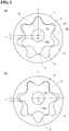
- Reference numeral 2a denotes an addendum of the inner rotor 2
- 2b denotes a dedendum of the inner rotor 2.
- the inner rotor 2 has a shaft hole 2c in its center.
- a tooth profile of the inner rotor 2 is formed using a base circle A that is concentric with the inner rotor, and a formation circle B and/or a dedendum formation circle C having a point j that is provided on the circumference thereof and passes through a reference point J serving as an intersection of the base circle A and the Y-axis.
- the base circle A is a circle having a radius extending from the inner rotor center to a boundary point between the addendum and the dedendum, and the point j starts to move from a position on the circle.
- L 1 represents a straight line connecting the inner rotor center O I and the reference point J
- L 2 represents a straight line connecting the inner rotor center O I to an addendum top T T
- ⁇ T represents an angle ⁇ SpaO 1 T T formed by three points, namely, a moving start point Spa of the center of the addendum formation circle B, the inner rotor center of O I , and the addendum top T T (a rotation angle from the straight line L 1 to L 2 ).
- the center pa of the addendum formation circle B moves toward the straight line L 2 through the angle ⁇ T from the moving start point Spa (this is a center position of the addendum formation circle B at a position where the point j coincides with the reference point J, and the moving start point Spa is on the straight line L 1 in Fig. 2 ) to a moving end point Lpa (this is on the straight line L 2 ).
- the circumferential angular velocity of the center pa of the addendum formation circle B is fixed.
- the center pa of the addendum formation circle B moves by a distance R in the radial direction of the base circle A.
- the rotating direction of the addendum formation circle B is the same as the moving direction of the angle ⁇ T . That is, when the rotating direction is right-handed, the moving direction of the addendum formation circle B is also right-handed.
- a dedendum curve can be drawn similarly.
- a center pa of the dedendum formation circle C having a diameter Cd is moved from a moving start point Spb toward a moving end point Lpb through an angle ⁇ B while causing the dedendum formation circle C to rotate at a constant angular velocity in a direction opposite the rotating direction of the addendum formation circle B.
- half of a tooth profile of the dedendum of the inner rotor is drawn by a locus formed when one point j on the circumference of the dedendum formation circle C moves from the reference point J to a dedendum bottom T B set on a straight line L 3 .
- the addendum formation circle B and the dedendum formation circle C move from the moving start points to the moving end points while keeping their diameters Bd and Cd constant, and half of the tooth profile of the addendum 2a of the inner rotor is drawn by the locus of the point j formed during movement.
- the tooth profile forming method is not limited to these methods.
- the object of the present invention is also achieved by a method in which the addendum formation circle B and the dedendum formation circle C move from the moving start points to the moving end points while changing their diameters, and halves of the tooth profiles of the addendum and dedendum of the inner rotor are drawn by the loci of the points j formed during movement.
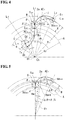
- Figures 4 and 5 show the principle of formation of the tooth profile using formation circles whose diameters change.
- Bd max represents the diameter of the addendum formation circle B at the moving start point
- L 1 represents a straight line connecting the inner rotor center O I and the reference point J
- L 2 represents a straight line connecting the inner rotor center O I and the addendum top T T
- ⁇ T represents an angle ⁇ SpaO I T T formed by three points, namely, the moving start point Spa of the center of the addendum formation circle B, the inner rotor center O I , and the addendum top T B (a rotation angle from the straight line L 1 to L 2 ).
- the center pa of the addendum formation circle B moves toward the straight line L 2 through the rotation angle ⁇ T from the moving start point Spa to the moving end point (this is on the straight line L 2 ).
- the circumferential angular velocity of the center pa of the addendum formation circle B is fixed.
- the center pa of the addendum formation circle B moves by a distance R in the radial direction of the base circle A.
- the addendum formation circle B rotates through the angle ⁇ while decreasing its diameter during a period in which the center pa of the addendum formation circle B moves from the moving start point Spa to the moving end point Lpa.
- the point j on the addendum formation circle B reaches the addendum top T T set on the straight line L 2 (this is at a position where a preset addendum circle having a diameter D T intersects the straight line L 2 ).
- Half of a tooth profile of an addendum 2a of the inner rotor is drawn by a locus formed when the point j moves during this.
- the diameter of the addendum formation circle B has changed to Bd min at the addendum top T T .
- the radius of curvature of the addendum can be made larger than in the tooth profile drawn using a formation circle having a fixed diameter. Further, it is possible to obtain a tooth profile in which the difference between the clearance near the tip clearance and the tip clearance is reduced.
- the rotating direction and the moving direction through the angle ⁇ T of the addendum formation circle B are made equal, and the tooth profile that is symmetric with respect to the straight line L 2 is formed by inverting the half of the tooth profile, which is drawn by the above-described method, with respect to the straight line L 2 .
- a dedendum curve can be drawn similarly.
- a dedendum formation circle C having a diameter Cd at a moving start point Spb is caused to rotate at a constant angular velocity in a direction opposite in the rotating direction of the addendum formation circle B, and is moved through an angle ⁇ B from the moving start point Spb toward a moving end point Lpb while decreasing its diameter.
- Half of a tooth profile of a dedendum of the inner rotor is drawn by a locus formed while one point j on the circumference of the dedendum formation circle C moves from the reference point J to a dedendum bottom T B set on the straight line L 3 (this is at a position where a preset dedendum circle having a diameter D B intersects the straight line L 3 ).
- a dedendum shape for one tooth can be obtained.
- the centers pa of the addendum formation circle B and the dedendum formation circle C move on curves AC 1 and AC 2 in which the change rate ⁇ R of the moving distance R is 0 at the moving end points Lpa and Lpb of the centers of the formation circles.
- the addendums do not become sharp, and the clearance near the tip clearance becomes stable. This achieves the effects of enhancing discharge performance (increasing the discharge amount), preventing noise during pump operation, and enhancing durability of the rotor.
- a cosine curve, a higher curve, an arc, an elliptic curve, or a curve formed by a combination of these curves and a straight line having a fixed inclination can be used for the curves AC 1 and AC 2 .
- the change rate ⁇ r of the diameter of the addendum formation circle B is preferably zero at the moving end point Lpa and Lpb of the center of the formation circle. This can easily increase the radius curvature of the addendum.
- the number of teeth of the used outer rotor 3 (the number of teeth is seven in Fig. 1 ) is larger by one than that of the inner rotor 2.
- a tooth profile of the outer rotor 3 is formed by the following procedure, as shown in Fig. 9 .
- the center O I of the inner rotor 2 makes one revolution on a circle S centered on the center O O of the outer rotor 3 and having a diameter (2e+t).
- the inner rotor 2 makes a 1/n rotation.
- An envelope of tooth profile curves formed by the revolution and rotation of the inner rotor is drawn. The envelope thus determined serves as a tooth profile.
- the shape of dedendums may be formed in a method similar to that for the addendums using the addendum formation circle C, or may adopt a tooth profile formed using a known trochoidal curve or a tooth profile using a cycloidal curve.
- the shape of addendums may adopt a tooth profile formed using a trochoidal curve or a tooth profile using a cycloidal curve.
- the tooth profile using the tooth profile curve of the present invention and the cycloidal curve in combination allows smooth engage with the outer rotor that is characteristic of the cycloidal curve, and can increase the tooth depth. The demand to increase the discharge amount is thereby satisfied.
- the addendum height and dedendum depth of the inner rotor are determined by the value of the radial moving distance R of the addendum formation circle B and the dedendum formation circle C. Since the value of the moving distance R can be freely set in the tooth profile to which the tooth profile curve of the present invention is applied, even when one of the addendum and the dedendum has a tooth profile defined by a trochoidal curve or a cycloidal curve, the degree of flexibility in setting the tooth depth is ensured.
- the inner rotor 2 and the outer rotor 3 described above are eccentrically arranged in combination to form the internal gear pump rotor 1.
- the internal gear pump rotor 1 is stored in a rotor chamber 6 of a pump housing 5 including a suction port 7 and a discharge port 8, thereby forming an internal gear pump 9.
- the inner rotor 2 is engaged with a driving shaft (not shown) by inserting the driving shaft in the shaft hole 2c of the inner rotor 2, and a driving force is transmitted from the driving shaft to rotate the inner rotor 2.
- the outer rotor 3 is rotated in a following manner. With this rotation, the capacity of a pump chamber 4 defined between the rotors increases and decreases, whereby fluid, such as oil, is sucked and discharged.
- the center of the formation circle moves on the curve such that the distance from the inner rotor center to the center of the formation circle increases from the moving start end toward the moving terminal end.
- the center of the formation angle moves on the curve such that the distance decreases.
- the formation circle rotates.
- the tooth profile of at least one of the addendum and the dedendum of the inner rotor 2 is formed by the locus of one point on the circumference of the formation circle.
- the tooth depth of the inner rotor can be made larger than the tooth depth in the conventional internal gear pump that adopts a tooth profile of a trochoidal curve or a tooth profile of a cycloidal curve. For this reason, the capacity of the pump chamber 4 defined between the teeth of the inner rotor 2 and the outer rotor 3 becomes larger than in the conventional pump, and this increases the discharge amount of the pump.
- the number of teeth of the inner rotor can be made larger than the number of teeth of the conventional internal gear pump that adopts the tooth profile of a trochoidal curve or the tooth profile of a cycloidal curve. For this reason, the number of pump chambers 4 defined between the teeth of the inner rotor 2 and the outer rotor 3 becomes larger than in the conventional pump, and this increases the discharge amount of the pump.
- the degree of flexibility in designing the tooth profile increases.
- an addendum curve or a dedendum curve of the inner rotor is formed using the addendum formation circle or the dedendum formation circle whose diameter decreases by a fixed amount per fixed rotation angle
- the degree of flexibility in designing the tooth profile is particularly high because the clearance near the tip clearance can be adjusted by changing the shape of the addendum.
- Figure 8 shows a tooth profile drawn in the method shown in Fig. 4 by increasing the change amount in distance from the inner rotor center O I to the center of the addendum formation circle B by an amount corresponding to the reduction amount of the diameter of the addendum formation circle B while reducing the diameter of the addendum formation circle B under a condition that the addendum diameter (diameter of the addendum circle) of the inner rotor 2 is fixed.
- the radius of curvature of the addendum can be made larger and the clearance between the addendum and the adjacency of the addendum of the outer rotor can be made smaller than in the tooth profile of the inner rotor shown in Fig. 1 formed using the addendum formation circle B having the fixed diameter. For this reason, the capacity efficiency of the pump improves.
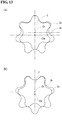
- FIGS. 6 and 7 show pump rotors 1 according to other embodiments of the present invention.
- An internal gear pump rotor shown in Fig. 6 is designed in a manner such that the tooth profile curve of the present invention is applied to both an addendum 2a and a dedendum 2b of an inner rotor 2.
- the tooth profile curve of the present invention is applied to an addendum 2a of an inner rotor 2
- a dedendum 2b is defined by a cycloidal curve.
- a formation circle having a fixed diameter is used to form the tooth profile curve of the present invention.
- the internal gear pump rotor of the present invention has flexibility in designing the tooth profile even when the formation circle having the fixed diameter is used.
- a cycloidal curve of an addendum was formed by rolling an externally rolling circle having a diameter of 3.25 mm on a base circle having a diameter of 39 mm without slipping thereon.
- a cycloidal curve of a dedendum was formed by rolling an internally rolling circle having a diameter of 3.25 mm on the base circle having a diameter of 39 mm without slipping thereon.
- Addendum diameters diameters of addendum circles
- dedendum diameters diameters of dedendum circles
- amount of eccentricity e of the formed inner and outer rotors are as follows:
- a cycloidal curve of an addendum was formed by rolling an externally rolling circle having a diameter of 2.4 mm on a base circle having a diameter of 41 mm without slipping thereon.
- a tooth profile curve of the present embodiment at a dedendum was formed by the method shown in Fig. 2 using the base circle A and a formation circle C having a fixed diameter.
- specifications are as follows:
- Addendum diameters and dedendum diameters, and the amount of eccentricity e of the formed inner and outer rotors are as follows. These numerical values are also the same in the following second, third, and fourth embodiments.
- a tooth profile curve of the present embodiment at an addendum was formed by the method shown in Fig. 2 using a base circle A and a formation circle B having a fixed diameter.
- specifications are as follows:
- a tooth profile curve of the present embodiment at a dedendum was formed by the method shown in Fig. 2 using the base circle A and a formation circle C having a fixed diameter described with reference to Fig. 2 .
- specifications are as follows:
- a tooth profile curve of the present embodiment at an addendum was formed by the method shown in Fig. 2 using a base circle A and a formation circle B having a fixed diameter.
- specifications are as follows:
- a tooth profile curve of the present embodiment at a dedendum was formed by the method shown in Fig. 2 using the base circle A and a formation circle C having a fixed diameter.
- specifications are as follows:
- a tooth profile curve of the present embodiment at an addendum was formed by the method shown in Fig. 4 using a base circle A and a formation circle B whose diameter changes during movement.
- specifications are as follows:
- a tooth profile curve of the present embodiment at a dedendum of the fourth embodiment was formed by the method shown in Fig. 4 using the base circle A and a formation circle C whose diameter changes during movement.
- specifications are as follows:
- Internal gear pumps were constructed by incorporating, into the pump housing, the internal gear pump rotors formed by combining the inner rotors and the outer rotors having the above-described specifications. Then, discharge amounts of the pumps provided under the following test conditions were compared. The result of comparison is shown in the following Table I.
- the tooth depth of the rotor and the discharge amount of the pump can be made larger than in the conventional pump in which the tooth profile of the inner rotor is formed by a trochoidal curve (see Fig. 16 ) or the conventional pump in which the tooth profile is formed by a cycloidal curve (see Fig. 17 ).
- the diameter of the base circle and the diameters of the addendum formation circle and the dedendum formation circle can be freely set, the number of teeth can be freely set.
- discharge pulsation of the pump can be reduced by increasing the number of teeth.
- the discharge amount increases, compared with the comparative example. From this result, it is shown that the object of the present invention can be achieved even when the diameter of the formation circle changes during movement.
- the pump rotor and the internal gear pump according to the present invention can be preferably used, for example, as oil pumps for lubrication of the car engine and for an automatic t transmission (AT).
- AT automatic t transmission
Claims (9)
- Verfahren zur Bildung eines Zahnprofils eines Rotors für eine Innenzahnradpumpe, der in Kombination einen inneren Rotor (2) mit einer Anzahl n an Zähnen und einen Außenrotor (3) mit einer Anzahl (n+1) Zähnen hat und der durch Änderung eines Fassungsvermögens einer Pumpenkammer (4), die zwischen den Zähnen des Rotors aufgrund der Drehung der Rotoren gebildet ist, ein Fluid ansaugt und ausgibt,
wobei Formierungskreise (B, C) sich derart bewegen, das eine Zahnkopfhöhenkurve und/oder eine Zahnfußhöhenkurve eines Zahnprofils des inneren Rotors (2) durch eine Ortskurve gebildet wird, die während der Bewegung durch einen Punkt (j) gezeichnet wird, der mit einem Referenzpunkt (J) auf einem Basiskreis (A) zusammenfällt, der zu einem Mittelpunkt (OI) des inneren Rotors konzentrisch ist und der auf den Formierungskreisen (B, C) liegt, dadurch gekennzeichnet, dass
die Formierungskreise (B, C) sich so bewegen, dass sie die folgenden Bedingungen erfüllen:bei Änderung radialer Abstände von dem Mittelpunkt (OI) des inneren Rotors zu Mittelpunkten der Formierungskreise um eine Strecke (R) bewegen sich die Mittelpunkte (pa) der Formierungskreise (B, C) von Bewegungsanfangspunkten (Spa, Spb), an denen die Mittelpunkt positioniert sind, wenn die Formierungskreise (B, C) so angeordnet sind, dass der Punkt (j) mit dem Referenzpunkt (J) auf dem Basiskreis (A) übereinstimmt, bis zu Bewegungsendpunkten (Lpa, Lpb), an denen die Mittelpunkte positioniert sind, wenn die Formierungskreise (B, C) so angeordnet sind, dass der Punkt (j) an einer obersten Zahnkopfhöhe (TT) oder an einer untersten Zahnfußhöhe (TB) positioniert ist; unddie Formierungskreise (B, C) drehen sich um einen Winkel θ mit konstanter Winkelgeschwindigkeit in der gleichen Richtung wie Bewegungsrichtungen der Kreise. - Verfahren nach Anspruch 1, wobei die Mittelpunkte (pa) der Formierungskreise (B, C), die einen festen Durchmesser haben, sich von den Bewegungsanfangspunkten Spa und Spb zu den Bewegungsendpunkten Lpa und Lpb bewegen, und die Zahnkopfhöhenkurve und/oder die Zahnfußhöhenkurve des Zahnprofils des inneren Rotors (2) durch eine Ortskurve erzeugt ist, die durch einen Punkt (j) auf Außenumfängen der Formierungskreise (B, C), die den festen Durchmesser haben, gezeichnet wird.
- Verfahren nach Anspruch 1, wobei die Mittelpunkte (pa) der Formierungskreise (B, C) sich von den Bewegungsanfangspunkten (Spa, Spb) zu den Bewegungsendpunkten (Lpa, Lpb) bewegen, während die Durchmesser der Formierungskreise (B, C) kleiner werden, und die Zahnkopfhöhenkurve und/oder die Zahnfußhöhenkurve des Zahnprofils des inneren Rotors (2) durch eine Ortskurve erzeugt ist, die durch einen Punkt (j) auf Außenumfängen der Formierungskreise (B, C), deren Durchmesser sich ändern, gezeichnet wird.
- Verfahren nach einem der Ansprüche 1 bis 3, wobei die Mittelpunkte (pa) der Formierungskreise sich auf Kurven (AC1, AC2) bewegen, auf denen eine Änderungsrate (ΔR) der Abstände von dem Mittelpunkt des inneren Rotors OI zu den Mittelpunkten (pa) der Formierungskreise an den Bewegungsendpunkten 0 beträgt.
- Verfahren nach Anspruch 4, wobei die Kurven (AC1, AC2) Sinuskurven sind.
- Verfahren nach Anspruch 4 oder 5, wobei die Änderungsrate (ΔR) der Abstände zwischen den Kurven (AC1, AC2) und dem Mittelpunkt des inneren Rotors (OI) den folgenden Ausdruck erfüllt:

- Verfahren nach einem der Ansprüche 3 bis 6, wobei Durchmesser (Bd, Cd) der Formierungskreise (B, C) an den Bewegungsendpunkten (Lpa, Lpb) größer oder gleich dem 0,2-fachen von Durchmessern an den Bewegungsanfangspunkten (Spa, Spb) und kleiner als oder gleich zu den Durchmessern an den Bewegungsanfangspunkten (Spa, Spb) sind.
- Verfahren nach einem der Ansprüche 1 bis 7,
wobei der Mittelpunkt (OI) des inneren Rotors (2) einen Umlauf auf einem Kreis (S) ausführt, dessen Mittelpunkt an einem Mittelpunkt (OO) des äußeren Rotors (3) liegt und einen Durchmesser (2e+t) hat,
wobei währenddessen der innere Rotor (2) eine 1/n-Drehung macht,
wobei eine Einhüllende einer Gruppe aus Zahnprofilkurven, die durch den Umlauf und die Drehung des inneren Rotors erzeugt werden, gezeichnet wird,
wobei der äußere Rotor die ermittelte Einhüllende als ein Zahnprofil hat und wobei gilt
e: Größe der Exzentrizität zwischen dem Mittelpunkt des inneren Rotors und dem Mittelpunkt des äußeren Rotors
t: Spaltgröße am vorderen Ende
n: Anzahl an Zähnen des inneren Rotors. - Verfahren nach einem der Ansprüche 1 bis 8, wobei der Pumpenrotor (1) in einer Rotorkammer (6) untergebracht ist, die in einem Pumpengehäuse (5) vorgesehen ist.
Applications Claiming Priority (2)
| Application Number | Priority Date | Filing Date | Title |
|---|---|---|---|
| JP2008205311 | 2008-08-08 | ||
| PCT/JP2009/063779 WO2010016473A1 (ja) | 2008-08-08 | 2009-08-04 | 内接歯車式ポンプ用ロータとそれを用いた内接歯車式ポンプ |
Publications (3)
| Publication Number | Publication Date |
|---|---|
| EP2206923A1 EP2206923A1 (de) | 2010-07-14 |
| EP2206923A4 EP2206923A4 (de) | 2014-10-29 |
| EP2206923B1 true EP2206923B1 (de) | 2017-12-06 |
Family
ID=41663690
Family Applications (1)
| Application Number | Title | Priority Date | Filing Date |
|---|---|---|---|
| EP09804956.2A Active EP2206923B1 (de) | 2008-08-08 | 2009-08-04 | Rotor für eine innenzahnradpumpe und innenzahnradpumpe mit dem rotor |
Country Status (7)
| Country | Link |
|---|---|
| US (1) | US8632323B2 (de) |
| EP (1) | EP2206923B1 (de) |
| JP (1) | JP4600844B2 (de) |
| KR (1) | KR101107907B1 (de) |
| CN (1) | CN101821510B (de) |
| ES (1) | ES2656432T3 (de) |
| WO (1) | WO2010016473A1 (de) |
Families Citing this family (21)
| Publication number | Priority date | Publication date | Assignee | Title |
|---|---|---|---|---|
| CN102510952B (zh) * | 2009-11-16 | 2017-09-29 | 住友电工烧结合金株式会社 | 泵转子以及使用该转子的内齿轮泵 |
| JP5194308B2 (ja) * | 2010-09-29 | 2013-05-08 | 住友電工焼結合金株式会社 | 内接歯車式ポンプ用ロータ |
| JP2012137024A (ja) * | 2010-12-27 | 2012-07-19 | Sumitomo Electric Sintered Alloy Ltd | 内接歯車式ポンプ用ロータ |
| JP5194310B2 (ja) * | 2010-12-27 | 2013-05-08 | 住友電工焼結合金株式会社 | 内接歯車式ポンプ用ロータ |
| JP5765655B2 (ja) | 2011-10-21 | 2015-08-19 | 住友電工焼結合金株式会社 | 内接歯車ポンプ |
| JP5674044B2 (ja) * | 2011-10-24 | 2015-02-18 | 住友電工焼結合金株式会社 | 内接歯車ポンプ |
| JP2013148000A (ja) | 2012-01-19 | 2013-08-01 | Sumitomo Electric Sintered Alloy Ltd | 内接歯車ポンプ |
| JP5561287B2 (ja) * | 2012-01-25 | 2014-07-30 | 住友電工焼結合金株式会社 | アウターロータの歯形創成方法と内接歯車ポンプ |
| KR101914329B1 (ko) | 2012-04-17 | 2018-11-01 | 스미또모 덴꼬 쇼오께쯔 고오낑 가부시끼가이샤 | 펌프용 로터와 이를 이용한 내접 기어식 펌프 |
| CN102678829B (zh) * | 2012-05-28 | 2014-08-20 | 阜新德尔汽车部件股份有限公司 | 液压装置用圆弧形齿廓螺旋齿轮 |
| CN103089963B (zh) * | 2013-01-28 | 2015-09-30 | 西安理工大学 | 内啮合齿廓副 |
| CN103089616B (zh) * | 2013-01-28 | 2015-11-18 | 西安理工大学 | 一种内啮合齿廓副 |
| JP6080300B2 (ja) * | 2013-03-19 | 2017-02-15 | アイシン機工株式会社 | ギヤポンプおよびインナーロータの製造方法 |
| JP6080635B2 (ja) * | 2013-03-19 | 2017-02-15 | アイシン機工株式会社 | ギヤポンプおよびインナーロータの製造方法 |
| DE102013004861B3 (de) * | 2013-03-21 | 2014-02-27 | Voith Patent Gmbh | Verzahnung eines Zahnrads |
| JP6382674B2 (ja) * | 2014-10-07 | 2018-08-29 | 豊興工業株式会社 | 内接歯車ポンプ |
| US10180137B2 (en) | 2015-11-05 | 2019-01-15 | Ford Global Technologies, Llc | Remanufacturing a transmission pump assembly |
| JP6863587B2 (ja) * | 2017-08-08 | 2021-04-21 | 住友電工焼結合金株式会社 | 高効率内接歯車式ポンプ |
| KR102033258B1 (ko) | 2018-10-19 | 2019-10-16 | 군산대학교산학협력단 | 내접기어식 펌프용 고용량 고성능 로터치형 설계방법 및 이 설계방법에 따라 제작된 로터 |
| KR102040416B1 (ko) | 2018-11-06 | 2019-11-04 | 군산대학교산학협력단 | 짝꿍 로터치형 생성방법 및 이 생성방법에 따라 제작된 짝꿍 로터 |
| KR102187157B1 (ko) * | 2020-02-25 | 2020-12-04 | 명화공업주식회사 | 내접 기어식 펌프용 로터 치형 설계방법 및 내접 기어식 펌프용 로터 |
Family Cites Families (23)
| Publication number | Priority date | Publication date | Assignee | Title |
|---|---|---|---|---|
| US2421463A (en) * | 1944-06-01 | 1947-06-03 | Eaton Mfg Co | Gear element |
| US2960884A (en) * | 1954-11-30 | 1960-11-22 | Hill Entpr Inc | Rounded tooth tips for pointed rotoid teeth |
| DE2911415C2 (de) * | 1979-03-23 | 1982-04-15 | Karl Prof.Dr.-Ing. 3000 Hannover Bammert | Parallel- und außenachsige Rotationskolbenmaschine mit Kämmeingriff |
| JPS5979083A (ja) * | 1982-10-27 | 1984-05-08 | Sumitomo Electric Ind Ltd | 回転ポンプ用ロ−タ− |
| JPS61201892A (ja) | 1985-03-05 | 1986-09-06 | Yamada Seisakusho:Kk | トロコイド噛み合いする内接歯車ポンプのインナ−ロ−タ−曲線修正方法 |
| DE4200883C1 (de) * | 1992-01-15 | 1993-04-15 | Siegfried A. Dipl.-Ing. 7960 Aulendorf De Eisenmann | |
| JP2836426B2 (ja) * | 1993-03-26 | 1998-12-14 | 株式会社日立製作所 | 遊星歯車装置及び増減速歯車装置 |
| DE4311165C2 (de) * | 1993-04-05 | 1995-02-02 | Danfoss As | Hydraulische Maschine |
| DE4311168C2 (de) * | 1993-04-05 | 1995-01-12 | Danfoss As | Hydraulische Maschine |
| CN1073704C (zh) * | 1996-01-22 | 2001-10-24 | 华中理工大学 | 一种水平向拾震器 |
| US6101892A (en) * | 1997-04-10 | 2000-08-15 | Genesis Partners, L.P. | Gear form constructions |
| US6077059A (en) * | 1997-04-11 | 2000-06-20 | Mitsubishi Materials Corporation | Oil pump rotor |
| ES2205538T3 (es) * | 1997-09-04 | 2004-05-01 | Sumitomo Electric Industries, Ltd. | Bomba de engranajes internos. |
| EP1340912B1 (de) | 2002-03-01 | 2005-02-02 | Hermann Härle | Zahnringmaschine mit Zahnlaufspiel |
| US6902507B2 (en) * | 2002-04-11 | 2005-06-07 | Richard N. Ballard | Roller cam assembly |
| JP3917026B2 (ja) * | 2002-07-10 | 2007-05-23 | アイシン精機株式会社 | オイルポンプロータ |
| US7118359B2 (en) * | 2002-07-18 | 2006-10-10 | Mitsubishi Materials Corporation | Oil pump rotor |
| EP1559912B1 (de) * | 2002-10-29 | 2015-12-09 | Diamet Corporation | Ölpumpenrotoreinheit mit innenverzahnung |
| JP4136957B2 (ja) | 2003-03-25 | 2008-08-20 | 住友電工焼結合金株式会社 | 内接歯車式ポンプ |
| JP2006009616A (ja) * | 2004-06-23 | 2006-01-12 | Sumitomo Denko Shoketsu Gokin Kk | 内接歯車式ポンプ |
| CN1740569A (zh) | 2005-09-14 | 2006-03-01 | 中国第一汽车集团公司 | 变基径摆线转子机油泵 |
| EP1927752B1 (de) * | 2005-09-22 | 2018-09-12 | Aisin Seiki Kabushiki Kaisha | Ölpumpenrotor |
| JP2007255292A (ja) | 2006-03-23 | 2007-10-04 | Sumitomo Denko Shoketsu Gokin Kk | 内接歯車ポンプ |
-
2009
- 2009-08-04 WO PCT/JP2009/063779 patent/WO2010016473A1/ja active Application Filing
- 2009-08-04 CN CN2009801006411A patent/CN101821510B/zh active Active
- 2009-08-04 JP JP2010501304A patent/JP4600844B2/ja active Active
- 2009-08-04 KR KR1020107006842A patent/KR101107907B1/ko active IP Right Grant
- 2009-08-04 ES ES09804956.2T patent/ES2656432T3/es active Active
- 2009-08-04 EP EP09804956.2A patent/EP2206923B1/de active Active
- 2009-08-04 US US12/682,025 patent/US8632323B2/en active Active
Non-Patent Citations (1)
| Title |
|---|
| None * |
Also Published As
| Publication number | Publication date |
|---|---|
| CN101821510B (zh) | 2012-09-05 |
| KR20100059922A (ko) | 2010-06-04 |
| JP4600844B2 (ja) | 2010-12-22 |
| KR101107907B1 (ko) | 2012-01-25 |
| US20100209276A1 (en) | 2010-08-19 |
| CN101821510A (zh) | 2010-09-01 |
| WO2010016473A1 (ja) | 2010-02-11 |
| JPWO2010016473A1 (ja) | 2012-01-26 |
| EP2206923A1 (de) | 2010-07-14 |
| ES2656432T3 (es) | 2018-02-27 |
| EP2206923A4 (de) | 2014-10-29 |
| US8632323B2 (en) | 2014-01-21 |
Similar Documents
| Publication | Publication Date | Title |
|---|---|---|
| EP2206923B1 (de) | Rotor für eine innenzahnradpumpe und innenzahnradpumpe mit dem rotor | |
| US7407373B2 (en) | Internal gear pump and an inner rotor of such a pump | |
| US8096795B2 (en) | Oil pump rotor | |
| US8360762B2 (en) | Oil pump rotor | |
| EP1462653B1 (de) | Innenzahnradpumpe | |
| EP2469092B1 (de) | Rotor für eine pumpe und innenzahnradpumpe damit | |
| KR100345406B1 (ko) | 오일펌프로우터 | |
| EP2759706B1 (de) | Rotor für eine pumpe und innenzahnradpumpe damit | |
| JP6982780B2 (ja) | 歯車ポンプ用ロータおよび歯車ポンプ | |
| JP4485770B2 (ja) | オイルポンプロータ | |
| JP2014181619A (ja) | ギヤポンプおよびインナーロータの製造方法 | |
| US9541085B2 (en) | Internal gear pump | |
| JP2006009616A (ja) | 内接歯車式ポンプ | |
| JP5194308B2 (ja) | 内接歯車式ポンプ用ロータ | |
| JP5561287B2 (ja) | アウターロータの歯形創成方法と内接歯車ポンプ | |
| JPH11264381A (ja) | オイルポンプロータ | |
| JP2003322088A (ja) | オイルポンプロータ | |
| JP4393943B2 (ja) | オイルポンプロータ | |
| JP2003322089A (ja) | オイルポンプロータ | |
| KR20120074898A (ko) | 지로터 펌프 및 그 설계 방법 | |
| JP2013060924A (ja) | 内接歯車ポンプ | |
| JP2006009618A (ja) | 内接歯車式ポンプ |
Legal Events
| Date | Code | Title | Description |
|---|---|---|---|
| PUAI | Public reference made under article 153(3) epc to a published international application that has entered the european phase |
Free format text: ORIGINAL CODE: 0009012 |
|
| 17P | Request for examination filed |
Effective date: 20100330 |
|
| AK | Designated contracting states |
Kind code of ref document: A1 Designated state(s): AT BE BG CH CY CZ DE DK EE ES FI FR GB GR HR HU IE IS IT LI LT LU LV MC MK MT NL NO PL PT RO SE SI SK SM TR |
|
| AX | Request for extension of the european patent |
Extension state: AL BA RS |
|
| DAX | Request for extension of the european patent (deleted) | ||
| REG | Reference to a national code |
Ref country code: DE Ref legal event code: R079 Ref document number: 602009049769 Country of ref document: DE Free format text: PREVIOUS MAIN CLASS: F04C0002100000 Ipc: F04C0002080000 |
|
| A4 | Supplementary search report drawn up and despatched |
Effective date: 20140925 |
|
| RIC1 | Information provided on ipc code assigned before grant |
Ipc: F04C 2/10 20060101ALI20140919BHEP Ipc: F04C 2/08 20060101AFI20140919BHEP |
|
| 17Q | First examination report despatched |
Effective date: 20161019 |
|
| GRAP | Despatch of communication of intention to grant a patent |
Free format text: ORIGINAL CODE: EPIDOSNIGR1 |
|
| INTG | Intention to grant announced |
Effective date: 20170629 |
|
| GRAS | Grant fee paid |
Free format text: ORIGINAL CODE: EPIDOSNIGR3 |
|
| GRAA | (expected) grant |
Free format text: ORIGINAL CODE: 0009210 |
|
| AK | Designated contracting states |
Kind code of ref document: B1 Designated state(s): AT BE BG CH CY CZ DE DK EE ES FI FR GB GR HR HU IE IS IT LI LT LU LV MC MK MT NL NO PL PT RO SE SI SK SM TR |
|
| REG | Reference to a national code |
Ref country code: GB Ref legal event code: FG4D |
|
| REG | Reference to a national code |
Ref country code: AT Ref legal event code: REF Ref document number: 952635 Country of ref document: AT Kind code of ref document: T Effective date: 20171215 Ref country code: CH Ref legal event code: EP |
|
| REG | Reference to a national code |
Ref country code: IE Ref legal event code: FG4D |
|
| REG | Reference to a national code |
Ref country code: DE Ref legal event code: R096 Ref document number: 602009049769 Country of ref document: DE |
|
| REG | Reference to a national code |
Ref country code: ES Ref legal event code: FG2A Ref document number: 2656432 Country of ref document: ES Kind code of ref document: T3 Effective date: 20180227 |
|
| REG | Reference to a national code |
Ref country code: NL Ref legal event code: MP Effective date: 20171206 |
|
| REG | Reference to a national code |
Ref country code: LT Ref legal event code: MG4D |
|
| PG25 | Lapsed in a contracting state [announced via postgrant information from national office to epo] |
Ref country code: LT Free format text: LAPSE BECAUSE OF FAILURE TO SUBMIT A TRANSLATION OF THE DESCRIPTION OR TO PAY THE FEE WITHIN THE PRESCRIBED TIME-LIMIT Effective date: 20171206 Ref country code: FI Free format text: LAPSE BECAUSE OF FAILURE TO SUBMIT A TRANSLATION OF THE DESCRIPTION OR TO PAY THE FEE WITHIN THE PRESCRIBED TIME-LIMIT Effective date: 20171206 Ref country code: NO Free format text: LAPSE BECAUSE OF FAILURE TO SUBMIT A TRANSLATION OF THE DESCRIPTION OR TO PAY THE FEE WITHIN THE PRESCRIBED TIME-LIMIT Effective date: 20180306 Ref country code: SE Free format text: LAPSE BECAUSE OF FAILURE TO SUBMIT A TRANSLATION OF THE DESCRIPTION OR TO PAY THE FEE WITHIN THE PRESCRIBED TIME-LIMIT Effective date: 20171206 |
|
| PG25 | Lapsed in a contracting state [announced via postgrant information from national office to epo] |
Ref country code: GR Free format text: LAPSE BECAUSE OF FAILURE TO SUBMIT A TRANSLATION OF THE DESCRIPTION OR TO PAY THE FEE WITHIN THE PRESCRIBED TIME-LIMIT Effective date: 20180307 Ref country code: BG Free format text: LAPSE BECAUSE OF FAILURE TO SUBMIT A TRANSLATION OF THE DESCRIPTION OR TO PAY THE FEE WITHIN THE PRESCRIBED TIME-LIMIT Effective date: 20180306 Ref country code: LV Free format text: LAPSE BECAUSE OF FAILURE TO SUBMIT A TRANSLATION OF THE DESCRIPTION OR TO PAY THE FEE WITHIN THE PRESCRIBED TIME-LIMIT Effective date: 20171206 Ref country code: HR Free format text: LAPSE BECAUSE OF FAILURE TO SUBMIT A TRANSLATION OF THE DESCRIPTION OR TO PAY THE FEE WITHIN THE PRESCRIBED TIME-LIMIT Effective date: 20171206 |
|
| PG25 | Lapsed in a contracting state [announced via postgrant information from national office to epo] |
Ref country code: NL Free format text: LAPSE BECAUSE OF FAILURE TO SUBMIT A TRANSLATION OF THE DESCRIPTION OR TO PAY THE FEE WITHIN THE PRESCRIBED TIME-LIMIT Effective date: 20171206 |
|
| REG | Reference to a national code |
Ref country code: FR Ref legal event code: PLFP Year of fee payment: 10 |
|
| PG25 | Lapsed in a contracting state [announced via postgrant information from national office to epo] |
Ref country code: SK Free format text: LAPSE BECAUSE OF FAILURE TO SUBMIT A TRANSLATION OF THE DESCRIPTION OR TO PAY THE FEE WITHIN THE PRESCRIBED TIME-LIMIT Effective date: 20171206 Ref country code: EE Free format text: LAPSE BECAUSE OF FAILURE TO SUBMIT A TRANSLATION OF THE DESCRIPTION OR TO PAY THE FEE WITHIN THE PRESCRIBED TIME-LIMIT Effective date: 20171206 Ref country code: CZ Free format text: LAPSE BECAUSE OF FAILURE TO SUBMIT A TRANSLATION OF THE DESCRIPTION OR TO PAY THE FEE WITHIN THE PRESCRIBED TIME-LIMIT Effective date: 20171206 |
|
| PG25 | Lapsed in a contracting state [announced via postgrant information from national office to epo] |
Ref country code: SM Free format text: LAPSE BECAUSE OF FAILURE TO SUBMIT A TRANSLATION OF THE DESCRIPTION OR TO PAY THE FEE WITHIN THE PRESCRIBED TIME-LIMIT Effective date: 20171206 Ref country code: RO Free format text: LAPSE BECAUSE OF FAILURE TO SUBMIT A TRANSLATION OF THE DESCRIPTION OR TO PAY THE FEE WITHIN THE PRESCRIBED TIME-LIMIT Effective date: 20171206 Ref country code: PL Free format text: LAPSE BECAUSE OF FAILURE TO SUBMIT A TRANSLATION OF THE DESCRIPTION OR TO PAY THE FEE WITHIN THE PRESCRIBED TIME-LIMIT Effective date: 20171206 |
|
| REG | Reference to a national code |
Ref country code: DE Ref legal event code: R097 Ref document number: 602009049769 Country of ref document: DE |
|
| PLBE | No opposition filed within time limit |
Free format text: ORIGINAL CODE: 0009261 |
|
| STAA | Information on the status of an ep patent application or granted ep patent |
Free format text: STATUS: NO OPPOSITION FILED WITHIN TIME LIMIT |
|
| 26N | No opposition filed |
Effective date: 20180907 |
|
| PG25 | Lapsed in a contracting state [announced via postgrant information from national office to epo] |
Ref country code: SI Free format text: LAPSE BECAUSE OF FAILURE TO SUBMIT A TRANSLATION OF THE DESCRIPTION OR TO PAY THE FEE WITHIN THE PRESCRIBED TIME-LIMIT Effective date: 20171206 Ref country code: DK Free format text: LAPSE BECAUSE OF FAILURE TO SUBMIT A TRANSLATION OF THE DESCRIPTION OR TO PAY THE FEE WITHIN THE PRESCRIBED TIME-LIMIT Effective date: 20171206 |
|
| PG25 | Lapsed in a contracting state [announced via postgrant information from national office to epo] |
Ref country code: MC Free format text: LAPSE BECAUSE OF FAILURE TO SUBMIT A TRANSLATION OF THE DESCRIPTION OR TO PAY THE FEE WITHIN THE PRESCRIBED TIME-LIMIT Effective date: 20171206 |
|
| REG | Reference to a national code |
Ref country code: CH Ref legal event code: PL |
|
| PG25 | Lapsed in a contracting state [announced via postgrant information from national office to epo] |
Ref country code: LI Free format text: LAPSE BECAUSE OF NON-PAYMENT OF DUE FEES Effective date: 20180831 Ref country code: LU Free format text: LAPSE BECAUSE OF NON-PAYMENT OF DUE FEES Effective date: 20180804 Ref country code: CH Free format text: LAPSE BECAUSE OF NON-PAYMENT OF DUE FEES Effective date: 20180831 |
|
| REG | Reference to a national code |
Ref country code: BE Ref legal event code: MM Effective date: 20180831 |
|
| REG | Reference to a national code |
Ref country code: AT Ref legal event code: UEP Ref document number: 952635 Country of ref document: AT Kind code of ref document: T Effective date: 20171206 |
|
| REG | Reference to a national code |
Ref country code: IE Ref legal event code: MM4A |
|
| PG25 | Lapsed in a contracting state [announced via postgrant information from national office to epo] |
Ref country code: IE Free format text: LAPSE BECAUSE OF NON-PAYMENT OF DUE FEES Effective date: 20180804 |
|
| PG25 | Lapsed in a contracting state [announced via postgrant information from national office to epo] |
Ref country code: BE Free format text: LAPSE BECAUSE OF NON-PAYMENT OF DUE FEES Effective date: 20180831 |
|
| REG | Reference to a national code |
Ref country code: DE Ref legal event code: R082 Ref document number: 602009049769 Country of ref document: DE Representative=s name: MAIER, LL.M., MICHAEL C., DE Ref country code: DE Ref legal event code: R082 Ref document number: 602009049769 Country of ref document: DE Representative=s name: BOULT WADE TENNANT LLP, DE |
|
| PG25 | Lapsed in a contracting state [announced via postgrant information from national office to epo] |
Ref country code: MT Free format text: LAPSE BECAUSE OF NON-PAYMENT OF DUE FEES Effective date: 20180804 |
|
| REG | Reference to a national code |
Ref country code: DE Ref legal event code: R082 Ref document number: 602009049769 Country of ref document: DE Representative=s name: BOULT WADE TENNANT LLP, DE |
|
| PG25 | Lapsed in a contracting state [announced via postgrant information from national office to epo] |
Ref country code: TR Free format text: LAPSE BECAUSE OF FAILURE TO SUBMIT A TRANSLATION OF THE DESCRIPTION OR TO PAY THE FEE WITHIN THE PRESCRIBED TIME-LIMIT Effective date: 20171206 |
|
| PG25 | Lapsed in a contracting state [announced via postgrant information from national office to epo] |
Ref country code: PT Free format text: LAPSE BECAUSE OF FAILURE TO SUBMIT A TRANSLATION OF THE DESCRIPTION OR TO PAY THE FEE WITHIN THE PRESCRIBED TIME-LIMIT Effective date: 20171206 Ref country code: HU Free format text: LAPSE BECAUSE OF FAILURE TO SUBMIT A TRANSLATION OF THE DESCRIPTION OR TO PAY THE FEE WITHIN THE PRESCRIBED TIME-LIMIT; INVALID AB INITIO Effective date: 20090804 |
|
| PG25 | Lapsed in a contracting state [announced via postgrant information from national office to epo] |
Ref country code: MK Free format text: LAPSE BECAUSE OF NON-PAYMENT OF DUE FEES Effective date: 20171206 Ref country code: CY Free format text: LAPSE BECAUSE OF FAILURE TO SUBMIT A TRANSLATION OF THE DESCRIPTION OR TO PAY THE FEE WITHIN THE PRESCRIBED TIME-LIMIT Effective date: 20171206 |
|
| PG25 | Lapsed in a contracting state [announced via postgrant information from national office to epo] |
Ref country code: IS Free format text: LAPSE BECAUSE OF FAILURE TO SUBMIT A TRANSLATION OF THE DESCRIPTION OR TO PAY THE FEE WITHIN THE PRESCRIBED TIME-LIMIT Effective date: 20180406 |
|
| PGFP | Annual fee paid to national office [announced via postgrant information from national office to epo] |
Ref country code: FR Payment date: 20200715 Year of fee payment: 12 Ref country code: ES Payment date: 20200901 Year of fee payment: 12 Ref country code: GB Payment date: 20200722 Year of fee payment: 12 |
|
| PGFP | Annual fee paid to national office [announced via postgrant information from national office to epo] |
Ref country code: IT Payment date: 20200713 Year of fee payment: 12 Ref country code: AT Payment date: 20200728 Year of fee payment: 12 |
|
| REG | Reference to a national code |
Ref country code: AT Ref legal event code: MM01 Ref document number: 952635 Country of ref document: AT Kind code of ref document: T Effective date: 20210804 |
|
| GBPC | Gb: european patent ceased through non-payment of renewal fee |
Effective date: 20210804 |
|
| PG25 | Lapsed in a contracting state [announced via postgrant information from national office to epo] |
Ref country code: AT Free format text: LAPSE BECAUSE OF NON-PAYMENT OF DUE FEES Effective date: 20210804 |
|
| PG25 | Lapsed in a contracting state [announced via postgrant information from national office to epo] |
Ref country code: IT Free format text: LAPSE BECAUSE OF NON-PAYMENT OF DUE FEES Effective date: 20210804 Ref country code: GB Free format text: LAPSE BECAUSE OF NON-PAYMENT OF DUE FEES Effective date: 20210804 Ref country code: FR Free format text: LAPSE BECAUSE OF NON-PAYMENT OF DUE FEES Effective date: 20210831 |
|
| REG | Reference to a national code |
Ref country code: ES Ref legal event code: FD2A Effective date: 20221031 |
|
| PG25 | Lapsed in a contracting state [announced via postgrant information from national office to epo] |
Ref country code: ES Free format text: LAPSE BECAUSE OF NON-PAYMENT OF DUE FEES Effective date: 20210805 |
|
| P01 | Opt-out of the competence of the unified patent court (upc) registered |
Effective date: 20230515 |
|
| PGFP | Annual fee paid to national office [announced via postgrant information from national office to epo] |
Ref country code: DE Payment date: 20230627 Year of fee payment: 15 |