EP2200038A1 - Procédé d'enregistrement de données audio/video, dispositif d'enregistrement de données audio/video, support d'enregistrement de données et support d'enregistrement de programmes - Google Patents
Procédé d'enregistrement de données audio/video, dispositif d'enregistrement de données audio/video, support d'enregistrement de données et support d'enregistrement de programmes Download PDFInfo
- Publication number
- EP2200038A1 EP2200038A1 EP10158067A EP10158067A EP2200038A1 EP 2200038 A1 EP2200038 A1 EP 2200038A1 EP 10158067 A EP10158067 A EP 10158067A EP 10158067 A EP10158067 A EP 10158067A EP 2200038 A1 EP2200038 A1 EP 2200038A1
- Authority
- EP
- European Patent Office
- Prior art keywords
- data
- partial
- associated data
- management information
- recording
- Prior art date
- Legal status (The legal status is an assumption and is not a legal conclusion. Google has not performed a legal analysis and makes no representation as to the accuracy of the status listed.)
- Ceased
Links
Images


Classifications
-
- G—PHYSICS
- G11—INFORMATION STORAGE
- G11B—INFORMATION STORAGE BASED ON RELATIVE MOVEMENT BETWEEN RECORD CARRIER AND TRANSDUCER
- G11B27/00—Editing; Indexing; Addressing; Timing or synchronising; Monitoring; Measuring tape travel
- G11B27/02—Editing, e.g. varying the order of information signals recorded on, or reproduced from, record carriers
- G11B27/031—Electronic editing of digitised analogue information signals, e.g. audio or video signals
- G11B27/034—Electronic editing of digitised analogue information signals, e.g. audio or video signals on discs
-
- G—PHYSICS
- G11—INFORMATION STORAGE
- G11B—INFORMATION STORAGE BASED ON RELATIVE MOVEMENT BETWEEN RECORD CARRIER AND TRANSDUCER
- G11B20/00—Signal processing not specific to the method of recording or reproducing; Circuits therefor
- G11B20/10—Digital recording or reproducing
-
- G—PHYSICS
- G11—INFORMATION STORAGE
- G11B—INFORMATION STORAGE BASED ON RELATIVE MOVEMENT BETWEEN RECORD CARRIER AND TRANSDUCER
- G11B27/00—Editing; Indexing; Addressing; Timing or synchronising; Monitoring; Measuring tape travel
- G11B27/02—Editing, e.g. varying the order of information signals recorded on, or reproduced from, record carriers
- G11B27/031—Electronic editing of digitised analogue information signals, e.g. audio or video signals
- G11B27/036—Insert-editing
-
- G—PHYSICS
- G11—INFORMATION STORAGE
- G11B—INFORMATION STORAGE BASED ON RELATIVE MOVEMENT BETWEEN RECORD CARRIER AND TRANSDUCER
- G11B27/00—Editing; Indexing; Addressing; Timing or synchronising; Monitoring; Measuring tape travel
- G11B27/10—Indexing; Addressing; Timing or synchronising; Measuring tape travel
- G11B27/19—Indexing; Addressing; Timing or synchronising; Measuring tape travel by using information detectable on the record carrier
- G11B27/28—Indexing; Addressing; Timing or synchronising; Measuring tape travel by using information detectable on the record carrier by using information signals recorded by the same method as the main recording
- G11B27/30—Indexing; Addressing; Timing or synchronising; Measuring tape travel by using information detectable on the record carrier by using information signals recorded by the same method as the main recording on the same track as the main recording
- G11B27/3027—Indexing; Addressing; Timing or synchronising; Measuring tape travel by using information detectable on the record carrier by using information signals recorded by the same method as the main recording on the same track as the main recording used signal is digitally coded
-
- G—PHYSICS
- G11—INFORMATION STORAGE
- G11B—INFORMATION STORAGE BASED ON RELATIVE MOVEMENT BETWEEN RECORD CARRIER AND TRANSDUCER
- G11B27/00—Editing; Indexing; Addressing; Timing or synchronising; Monitoring; Measuring tape travel
- G11B27/10—Indexing; Addressing; Timing or synchronising; Measuring tape travel
- G11B27/19—Indexing; Addressing; Timing or synchronising; Measuring tape travel by using information detectable on the record carrier
- G11B27/28—Indexing; Addressing; Timing or synchronising; Measuring tape travel by using information detectable on the record carrier by using information signals recorded by the same method as the main recording
- G11B27/32—Indexing; Addressing; Timing or synchronising; Measuring tape travel by using information detectable on the record carrier by using information signals recorded by the same method as the main recording on separate auxiliary tracks of the same or an auxiliary record carrier
- G11B27/327—Table of contents
- G11B27/329—Table of contents on a disc [VTOC]
-
- H—ELECTRICITY
- H04—ELECTRIC COMMUNICATION TECHNIQUE
- H04N—PICTORIAL COMMUNICATION, e.g. TELEVISION
- H04N9/00—Details of colour television systems
- H04N9/79—Processing of colour television signals in connection with recording
- H04N9/80—Transformation of the television signal for recording, e.g. modulation, frequency changing; Inverse transformation for playback
- H04N9/804—Transformation of the television signal for recording, e.g. modulation, frequency changing; Inverse transformation for playback involving pulse code modulation of the colour picture signal components
- H04N9/8042—Transformation of the television signal for recording, e.g. modulation, frequency changing; Inverse transformation for playback involving pulse code modulation of the colour picture signal components involving data reduction
-
- G—PHYSICS
- G11—INFORMATION STORAGE
- G11B—INFORMATION STORAGE BASED ON RELATIVE MOVEMENT BETWEEN RECORD CARRIER AND TRANSDUCER
- G11B2220/00—Record carriers by type
- G11B2220/20—Disc-shaped record carriers
- G11B2220/21—Disc-shaped record carriers characterised in that the disc is of read-only, rewritable, or recordable type
- G11B2220/215—Recordable discs
- G11B2220/216—Rewritable discs
-
- G—PHYSICS
- G11—INFORMATION STORAGE
- G11B—INFORMATION STORAGE BASED ON RELATIVE MOVEMENT BETWEEN RECORD CARRIER AND TRANSDUCER
- G11B2220/00—Record carriers by type
- G11B2220/20—Disc-shaped record carriers
- G11B2220/25—Disc-shaped record carriers characterised in that the disc is based on a specific recording technology
- G11B2220/2537—Optical discs
- G11B2220/2562—DVDs [digital versatile discs]; Digital video discs; MMCDs; HDCDs
- G11B2220/2575—DVD-RAMs
-
- H—ELECTRICITY
- H04—ELECTRIC COMMUNICATION TECHNIQUE
- H04N—PICTORIAL COMMUNICATION, e.g. TELEVISION
- H04N5/00—Details of television systems
- H04N5/76—Television signal recording
- H04N5/84—Television signal recording using optical recording
- H04N5/85—Television signal recording using optical recording on discs or drums
-
- H—ELECTRICITY
- H04—ELECTRIC COMMUNICATION TECHNIQUE
- H04N—PICTORIAL COMMUNICATION, e.g. TELEVISION
- H04N9/00—Details of colour television systems
- H04N9/79—Processing of colour television signals in connection with recording
- H04N9/80—Transformation of the television signal for recording, e.g. modulation, frequency changing; Inverse transformation for playback
- H04N9/804—Transformation of the television signal for recording, e.g. modulation, frequency changing; Inverse transformation for playback involving pulse code modulation of the colour picture signal components
- H04N9/806—Transformation of the television signal for recording, e.g. modulation, frequency changing; Inverse transformation for playback involving pulse code modulation of the colour picture signal components with processing of the sound signal
- H04N9/8063—Transformation of the television signal for recording, e.g. modulation, frequency changing; Inverse transformation for playback involving pulse code modulation of the colour picture signal components with processing of the sound signal using time division multiplex of the PCM audio and PCM video signals
Definitions
- the present invention relates to (i) a method for recording image data and audio data onto a random accessible recording medium such as a hard disk, an optical disc, and a semiconductor memory; to (ii) a recording apparatus; and to (iii) a recording medium.
- a video digital recording/reproducing apparatus (hereinafter, referred to as "video disc recorder") using a disc medium has begun to be pervasive.
- video disc recorder A video digital recording/reproducing apparatus (hereinafter, referred to as "video disc recorder") using a disc medium has begun to be pervasive.
- the after-recording function refers to a technique for further adding information, especially audio information, to recorded audio information and/or recorded video information.
- a stream file 3000 is in compliance with a unique stream format, and is so structured that regions for storing the after-recorded data are inserted among original stream data (initially recorded video/audio data) divided at a predetermined reproduction time interval.
- the after-recorded data is reproduced in synchronism with the original stream data.
- Fig. 20(a) illustrates that an after-recording data region 3011 for storing after-recorded audio data that is to be reproduced in synchronism is inserted just before partial original stream data 3021.
- after-recording data regions 3012 and 3013 are inserted just before partial original stream data 3022 and 3023, respectively.
- the stream file 3000 is recorded onto an optical disc 3001 such that each set of partial original stream data and each after-recording data region are disposed physically adjacent to each other as shown in Fig. 20(b) .
- a real-time after-recording is ensured by setting reproduction time of the partial original stream data to such a value (roughly several seconds) that allows for the real-time after-recording and that is determined in consideration of a seeking time.
- MPEG-2 TS Transport Stream
- MPEG-2 PS Program Stream
- MPEG-2 PS Program Stream
- MPEG-2 PS Program Stream
- MPEG-2 PS is used for DVD-Video
- MPEG-2 TS is used for a data transfer format between devices by way of digital broadcasting or the IEEE-1394.
- MPEG-2 TS/PS It is determined in MPEG-2 TS/PS that video data and audio data are multiplexed such that no underflow and no overflow occur in respective buffer memories of an audio decoder and a video decoder that are in compliance with a decoder model set as a standard (reference).
- audio data corresponding to one second or longer is stored in each of the after-recording data regions.
- the MPEG-2 TS/PS decoder receives, at a time, the audio data corresponding to one second or longer. This causes overflow of the buffer memory of the audio decoder.
- the after-recording data region is multiplexed in the stream in accordance with the aforementioned MPEG-2 PS multiplexing rule; however, the after-recording function suffers from a difficulty in the real-time after-recording when a transfer rate to or from a disc is low.
- the after-recorded data and the original stream data are recorded onto different files such that each of the files is in compliance with the MPEG-2 PS multiplexing rule.
- a file containing the after-recorded data and a file containing the original stream data are alternately read out, so that a seeking operation is required to be repeated during the reproduction of the after-recorded result.
- the non-destructive editing refers to an editing that is virtually carried out by using reproduction route information instead of using the stream data on a disc.
- the technique is also disadvantageous in power consumption.
- the present invention is made in light of the problem, and its object is to provide a data recording method that allows reproduction and real-time after-recording in a general MPEG-2 PS/TS decoder, and allows less interruption of reproduction when a non-destructive edit is carried out with respect to an after-recorded result.
- a method, of the present invention for recording, onto a recording medium, (i) AV data obtained by multiplexing a plurality of sets of stream data in accordance with a predetermined multiplexing rule, and (ii) associated data to be reproduced in synchronism with the AV data, the method includes: (a) a first step of dividing the AV data into partial AV data and of dividing the associated data into partial associated data, in accordance with a predetermined interval; (b) a second step of securing, in the recording medium, a first continuous region for continuously storing a series of the partial AV data and the partial associated data; (c) a third step of continuously recording the partial AV data and the partial associated data onto the first continuous region; and (d) a fourth step of recording, onto the recording medium, file system management information for (i) managing the partial AV data and the partial associated data as different files, and (ii) managing information for handling the partial AV data and the partial associated data as the different files.
- the AV data e.g., original stream
- the associated data e.g., after-recorded data
- the partial AV data and the partial associated data have such scales (lengths) that ensure the seamless reproduction and the real-time after-recording, respectively.
- the partial AV data and the partial associated data thus obtained by the dividing are reproduced in synchronism with each other, and the partial AV data and the partial associated data are continuously recorded by performing the second step and the third step such that they are physically adjacent to each other.
- the file system management information recorded in the fourth step manages the partial AV data and the partial associated data as different files. This ensures the real-time after-recording, and allows reproduction with the use of a general MPEG-2 PS decoder whose non-destructive editing property is excellent. Because the partial AV data and the partial associated data are positioned adjacent to each other, the seeking occurs less frequently when the AV data and the associated data are reproduced in synchronism. That is, this provides margin for further synchronized reproduction with other data. For example, the reproduction is less likely to be interrupted even when graphics data is added as well as the after-recorded audio data by way of the non-destructive editing.
- the file system management information managing the partial AV data and the partial associated data as different files has the information indicating the correspondence relation between the partial AV data and the partial associated data, which are positioned adjacent to each other in the recording medium. By recording the information indicating the correspondence relation, it is possible to easily recognize respective positions of the continuously stored partial AV data and partial associated data even when the file system management information is not referred. This optimizes the data readout.
- the method of the present invention may further include: a fifth step of recording, onto the recording medium, (i) reproduction start time of the partial AV data, and (ii) correspondence information of the partial AV data and the partial associated data, both of which are disposed in the first continuous region.
- the arrangement allows easy specification of the position of the partial associated data (after-recording region) corresponding to the partial AV data to be after-recorded.
- the method of the present invention may further include: a sixth step of recording, onto the recording medium, information indicating whether or not the partial associated data is recorded adjacent to the corresponding partial AV data.
- the partial associated data being recorded is possibly discarded and the CA is newly recorded onto another region.
- the information managing the partial associated data indicates that no partial associated data is positioned adjacent to the relevant AV data. Therefore, it is possible to easily recognize parts in which the partial AV data and the partial associated data are not continuously recorded, during the non-destructive editing or reproduction of the non-destructively edited result. With this, the user can be notified in advance that the reproduction will be likely to be interrupted during the reproduction of the parts.
- Another method for recording, onto a recording medium, (i) AV data obtained by multiplexing a plurality of sets of stream data in accordance with a predetermined multiplexing rule, and (ii) associated data to be reproduced in synchronism with the AV data, the method includes: (a) a seventh step of dividing the AV data into partial AV data in accordance with a predetermined interval; (b) an eighth step of securing, in the recording medium, a first continuous region for continuously storing (i) a series of the partial AV data and (ii) partial reservation data for securing, during recording of the associated data, a region for storing partial associated data that is so divided as to correspond to the partial AV data; (c) a ninth step of continuously recording the partial AV data and the partial reservation data onto the first continuous region, while making sets of the partial reservation data; and (d) a tenth step of recording, onto the recording medium, file system management information for (i) managing the partial AV data and the partial reservation data as different files
- the AV data (e.g., original stream) to be recorded onto the recording medium is divided into partial AV data by performing the seventh step such that the partial AV data has a length (scale) that ensures the seamless reproduction and the real-time after-recording.
- the partial AV data thus obtained by the dividing and the partial reservation data are continuously recorded by performing the eighth step and the ninth step such that they are physically positioned adjacent to each other.
- the partial reservation data secures the region for storing the partial associated data that is to be reproduced in synchronism with the partial AV data.
- the file system management information recorded in the tenth step manages the partial AV data and the partial associated data as different files. This ensures the real-time after-recording during the recording of the associated data, and allows reproduction with the use of a general MPEG-2 PS decoder whose non-destructive editing property is excellent.
- the method may further include: (a) a eleventh step of dividing, during the recording of the associated data, the associated data into partial associated data in accordance with a predetermined interval; (b) a twelfth step of recording, during the recording of the associated data, the partial associated data onto the region secured by the partial reservation data which is stored in continuity with the partial AV data corresponding to the associated data; (c) a thirteenth step of recording, onto the recording medium during the recording of the associated data, file system management information for (i) managing the partial associated data as a different file from the respective files of the partial AV data and the partial reservation data, (ii) managing information for handling the partial associated data as a different file.
- the partial AV data and the partial associated data are positioned adjacent to each other, so that the seeking occurs less frequently when the AV data and the associated data are reproduced in synchronism. That is, this provides margin for further synchronized reproduction with other data. For example, the reproduction is less likely to be interrupted even when graphics data is added as well as the after-recorded audio data by way of the non-destructive editing.
- the file system management information managing the partial AV data and the partial associated data as different files has the information indicating the correspondence relation between the partial AV data and the partial associated data, which are positioned adjacent to each other in the recording medium.
- Fig. 2 is a block diagram illustrating a basic system of a video disc recorder that is common in Embodiments described below.
- the video disc recorder includes: a bus 100, a host CPU 101, a RAM 102, a ROM 103, a user interface 104, a system clock 105, an optical disc 106, a pickup 107, an ECC (Error Correcting Coding) decoder 108, an ECC encoder 109, an audio reproduction buffer 110, a video reproduction buffer 111, a de-multiplexer 112, a multiplexer 113, a recording buffer 114, an audio decoder 115, a video decoder 116, an audio encoder 117, a video encoder 118, an audio recording buffer 119, a video recording buffer 120, a de-multiplexer 121, an after-recording data reproduction buffer 122, a dividing processing section 123 (means for dividing into AV data and partial associated data), a vacant region management section 125 (means for securing a continuous region), a management information processing section 126, a camera (not shown in FIG. 2 , the
- the host CPU 101 controls, via the bus 100, the de-multiplexer 112, the multiplexer 113, the pickup 107, the audio decoder 115, the video decoder 116, the audio encoder 117, and the video encoder 118.
- data read out from the optical disc 106 via the pickup 107 is subjected to an error correction carried out by the ECC decoder 108.
- file system management information is processed by the management information processing section 126. Then, the data is sent to the de-multiplexer 112 or de-multiplexer 121.
- the de-multiplexer 112 sends audio data of the readout data to the audio reproduction buffer 110, and sends video data thereof to the video reproduction buffer 111.
- the de-multiplexer 121 sends the readout data to the after-recording data reproduction buffer 122 in accordance with an instruction from the host CPU 101.
- the audio decoder 115 reads out the data from the audio reproduction buffer 110 and the after-recording data reproduction buffer 122, and carries out decoding with respect to the readout data, in accordance with an instruction from the host CPU 101.
- the video decoder 116 reads out the data from the video reproduction buffer 111, and carries out decoding with respect to the readout data, in accordance with an instruction from the host CPU 101.
- the multiplexer 113 reads out the respective data from the audio recording buffer 119 and the video recording buffer 120, and carries out AV-multiplexing with respect to the readout data, and sends the AV-multiplexed data to the dividing processing section 123.
- the dividing processing section 123 divides the AV-multiplexed data at every predetermined interval, and sends the divided data to the recording buffer 114.
- the vacant region management section 125 secures a continuous region for the recording of the data
- the ECC encoder 109 adds an error correction code to the AV-multiplexed data read out from the recording buffer 114, and the pickup 107 records the data onto the secured continuous region in the optical disc 106.
- An encoding format of the audio data is MPEG-1 Layer-II defined by ISO/IEC 13818-3
- an encoding format of the video data is MPEG-2 defined by ISO/IEC13818-2.
- the optical disc 106 is a re-writable optical disc, such as DVD-RAM, in which 2048 byte is handled as one sector and in which 16 sectors constitute an ECC block for the sake of the error correction.
- Fig. 3(a) illustrates a directory/file structure
- Fig. 3(b) illustrates an example in which the directory/file structure is recorded in compliance with the UDF.
- An AVDP (Anchor Volume Descriptor Pointer) 602 shown in Fig. 3(b) corresponds to an entry point for a search for management information of the UDF, and is usually recorded in a 256-th sector, an N-th sector, or an (N - 256)-th sector (N refers to a maximum logical sector number).
- a VDS (Volume Descriptor Sequence) 601 stores management information about a volume. The volume is a region managed by the UDF, and one volume generally exists in one disc, and generally includes one partition.
- One FSD (File Set Descriptor) 603 exists in the partition. Position information in the partition is indicated by a logic block number that corresponds to a sector number counted from top of the partition. Note that one logic block corresponds to one sector.
- each partition includes a table indicating whether or not a logic block termed "space bitmap" has been allocated to each file.
- the FSD 603 includes position information of an FE 604 serving as a file entry (FE) of a root directory.
- the position information is referred to as "extent” including logic block numbers and the number of the logic blocks.
- the FE manages an aggregate of the extents. By rewriting, adding, and/or deleting each extent, it is possible for the FE to change order of sets of actual data constituting the file, and/or to carry out data insertion and data deletion.
- the FE 604 manages a region 605 storing an aggregate of file identifier descriptors (FIDs), each of which stores name(s) of a file and/or a directory just below the root directory.
- An FID 611 and an FID 612 in the region 605 include position information of FE 606 and FE 608, respectively.
- the FE 606 manages a filename of a file 621 and an aggregation of extents thereof, and the FE 608 manages a filename of a file 622 and an aggregation of extents thereof.
- the FE 606 manages, as the extents, a region 607 and a region 610, each of which is a region constituting the actual data of the file 621.
- An access to the actual data of the file 621 can be made by following the links in order of the AVDP 602, the VDS 601, the FSD 603, the FE 604, the FID 611, the FE 606, the region 607, and the region 610.
- Embodiment 1 of the present invention will be explained below with reference to Fig. 1 , and Fig. 4 through Fig. 18 .
- FIG. 4 A file/directory structure according to Embodiment 1 is explained with reference to Fig. 4 . As shown in Fig. 4 , data of Embodiment 1 is stored in five types of files.
- An original stream file (SHRP0001.M2P) is a file prepared per picture recording, and is in compliance with the MPEG-2 PS (Program Stream) format.
- An after-recording data file (SHRP0001.PRE) is a file for (i) securing a region for after-recording, and (ii) storing after-recorded data.
- An original stream management information file (SHRP0001.OMI) is a file for storing (i) time-address correspondence information about the original stream file; (ii) attribution information about the original stream file; (iii) attribution information about the after-recording data file; and (iv) information indicative of a correspondence correlation with the original stream file.
- the original stream management information file is provided per original stream file.
- a program information file (SHRP0001.PGM) is a file for storing information that specifies which parts in the stream or the data are to be reproduced and that specifies order of reproducing these parts. Note that the program corresponds to one of contents, and is a target to be reproduced in response to user's instruction.
- the four files above are newly prepared during a picture recording.
- the files have different extensions, but are arranged so that others are in common than the extensions for the purpose of clarifying a relation among the files.
- the after-recording data management information file reflects the overwriting.
- the program information file is also changed so that the added after-recorded audio data is also a target to be reproduced.
- the program information file is newly prepared, and stores one by one (i) filenames of the original stream management information file and/or the after-recording data management information file, each of which manages the data to be reproduced; and (ii) the parts of the data which the user wishes to reproduce. Note that respective data structures of the files will be explained later.
- the original stream file is explained with reference to Fig. 5 .
- Content of the original stream file is in compliance with the MPEG-2 PS format, and is constituted by the integral number of continuous units (CUs) as shown in Fig. 5(a) .
- Each CU is a recording unit by which the recording is carried out with respect to a disc.
- Length of the CU is so set as to ensure (i) seamless reproduction (reproduction during which an image and a sound are never interrupted) and (ii) real-time after-recording (audio recording carried out during a seamless reproduction of video to be subjected to the after-recording), irrespective of how the CUs constituting the AV stream are provided on the disc.
- a method for setting the length will be described later.
- Each CU is constituted by the integral number of video units (VUs) as shown in Fig. 5(b) .
- VU is a individually reproducible unit, and can be an entry point during a reproduction.
- the VU is constituted by the integral number of audio packs (A#1 through A#K) and video packs (V#1 through V#L).
- the audio packs and the video packs are so AV-multiplexed as to maintain an MPEG-2 PS compatible decoder model.
- a size of each pack is as large as a sector size such that excess data is not read out during readout of the disc.
- the video data to be packed is constituted by one or two GOPs (Groups of picture).
- the audio data to be packed is constituted by the integral number of AAUs (Audio Access Units).
- the GOP is a unit of image compression of the MPEG-2 video standard, and is constituted by a plurality of video frames (typically, 15 frames or so).
- the AAU is a unit of audio compression of the MPEG-1 Layer-II standard, and is constituted by 1152 sound waveform sample points. In cases where a sampling frequency is 48 kHz, reproduction time per AAU is 0.024 second.
- a sequence header (SH) is provided at a head of video data in each VU such that individual reproductions are carried out in the VU unit.
- a VU at the end of the CU is padded by a pack storing a padding packet such that the CU is constituted by the integral number of ECC blocks.
- the after-recording data file is constituted by the integral number of continuous areas (CAs).
- CAs continuous areas
- One CA corresponds to one CU in the original stream file, and stores after-recording data corresponding to the reproduction data of the corresponding CU.
- a CA#n stores after-recording audio data that is to be reproduced in synchronization with a CU#n of the original stream file.
- the CA is constituted by the integral number of ECC block(s).
- the after-recording data file is in compliance with the MPEG-2 PS format as the original stream file is.
- padding packets are recorded onto the after-recording data file.
- packs containing the after-recorded data are overwritten in the after-recording data file.
- the packs to be overwritten have SCRs (System Clock References) in pack headers and have PTSs (Presentation Time Stamps) in packet headers, respectively.
- SCRs and the PTSs suit to SCRs and PTSs of the corresponding audio packs in the original stream file, respectively. With this, the audio data of the original stream can be easily replaced with the after-recorded data by overwriting the audio packs of the CU with the corresponding audio packs of the CA.
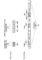
- Fig. 1(a) illustrates the original stream file (SHRP0001.M2P) and the after-recording data file (SHRP0001.PRE), which correspond to each other.
- the original stream file and the after-recording data file are recorded onto the optical disc 106 such that the CAs come just before the corresponding CUs, respectively (see Fig. 1(b) ).
- each CA and each CU each CA and each CU
- the interruption is less likely to occur during reproduction of a non-destructively edited result as described below. Because such a small CA in size is so positioned as to be read out prior to the CU, less buffer memory amount can be used for the synchronized reproduction.
- the reproduction time of the CU is determined such that the seamless reproduction is maintained when the after-recording is carried out by using, for sake of ensuring compatibility between devices, (i) a reference device (reference device model); and (ii) a reference after-recording algorism.
- the reference device model is made up of a pickup (not shown); an ECC encoder/decoder 501 connected to the pickup; a track buffer 502; a de-multiplexer 503; an after-recording buffer 504; an audio encoder 509; a video buffer 505; an audio buffer 506; a video decoder 507; and an audio decoder 508.
- the reference device model has the single pickup, readout of reproduction data from a disc 500 and recording of after-recorded data onto the disc 500 are carried out in a time-sharing manner.
- the reproduction data is read out from the disc 500 together with the CA.
- An ECC block (CA block) including the readout CA is sent from the track buffer 502 to the after-recording buffer 504.
- the audio encoder 509 sends the after-recorded data to the after-recording buffer 504 in a cycle of the AUU.
- the output data is overwritten in the corresponding CA block in the after-recording buffer 504.
- the CA block is recorded onto a predetermined ECC block, with the result that the after-recorded data is recorded.
- Rs indicates both (i) a transmission speed of the audio frame data to the ECC encoder 501, and (ii) a transmission speed of the audio frame data from the ECC decoder 501.
- Ta indicates a maximum period during which the readout and the recording are suspended via an access. Note that the period Ta includes seeking time, rotation latency time, and time required for completing of outputting, from the ECC decoder 501, of the data initially read out after the access.
- Embodiment 1 assumes that Rs is 20 Mbps and Ta is one second.
- the after-recording ensures that the after-recording buffer 504 is free from overflow and that the track buffer 502 is free from underflow, as long as the following condition is satisfied: Te i ⁇ Tr i + Tw i where Te(i) indicates maximum reproduction time of a CU#i that is an arbitrary CU in the AV stream; Tr(i) indicates maximum readout time including a division jump; and Tw(i) indicates maximum time for recording a CA#i that corresponds to the CU#.
- the condition is represented by the following Formula (2): ⁇ Te i ⁇ ⁇ i Tr i + Tw i where Ta indicates maximum round-trip time for the pickup to go to and return from the CA in the disc.
- a first term in a right side of Formula (3) indicates time for reading out a VU in a CU, and a second term therein indicates time for reading out the CA, and a third term therein indicates time for an access made by the division jump associated with the readouts.
- the division jump is carried out once at the maximum during the readout of the CU, so that Formula (3), i.e., Tr(i) indicates time corresponding to one access operation.
- a first term in a right side of Formula (4) indicates access time (forward-backward access time) for the pickup to go to and come back from the CA.
- the maximum access time Ta is used to represent the forward-backward access time because each CA can be recorded onto any position in the disc. Specifically, there is such a possibility that a CU which is being read out is positioned in an innermost side of the disc, and that a CA to be recorded is positioned in an outermost side of the disc. For this reason, the forward-backward access time is required to be estimated at the maximum value.
- the CA is recorded continuously onto the disc as described above, so that no access is made during the recording of the CA. This shortens time required for the recording of the CA, with the result that a lower limit value of the reproduction time of the CU can be restrained to be low.
- Te i ⁇ 3 ⁇ Ta ⁇ Rs / Rs - Ro - 2 ⁇ Ra Indicated by Rv is input speed and output speed of the video frame data, i.e., is video bit rate.
- the CU reproduction time lower limit value Temin 3 ⁇ Ta ⁇ Rs / Rs - Ro - 2 ⁇ Ra
- the setting of the upper limitation value of the CU reproduction time is carried out so as to allow for estimation of maximum amount of the retardation memory required for the synchronized reproduction of the after-recorded audio and the normal audio, and so as to ensure reproduction compatibility.
- the multiplexing interval lower limit value Temin is set according to the audio bit rate Ra and the video bit rate Rv; however, the lower limit value may be constant at any value as long as the lower limit value is based on maximum bit rate.
- reproduction time of the VU in the stream may be constant or variable as long as the reproduction time of the CU meets the aforementioned restriction.
- Embodiment 1 assumes that the division jump and the movement of the pickup to a previous CU are asynchronously carried out.
- a reason for this is as follows. That is, a condition for the real-time after-recording is stricter (the readout of the reproduction data is interrupted for a longer period of time) in cases where the division jump and the movement are asynchronously carried out, as compared with cases where the division jump and the movement are synchronously carried out. In other words, in cases where the real-time recording is attained when the division jump and the movement are asynchronously carried out, the real-time recording is accordingly attained when the division jump and the movement are synchronously carried out. This allows an increase in freedom of implementation of the present invention.
- Temin may be set on an assumption that the division jump and the movement of the pickup to the previous CU are carried out in synchronism.
- the second term in the right side of Formula 3 is omitted.
- the original stream management information file is made up of (i) o_attribute() for storing attribution information about the entire original stream file managed by the original stream management information file; (ii) video_unit_table() for storing information about the VU; (iii) p_attribute() for storing attribution information about the entire after-recording data file managed by the original stream management information file; and (iv) continuous_area_table() for storing information about the CA.
- the video_unit_table() is made up of (i) number_of_video_unit for indicating the number of the VUs; and (ii) video_unit_info() for storing information about each of the VUs.
- the video unit_info() is made up of (i) VU_flags for indicating various kinds of attribution information about a predetermined VU; (ii) VU_PTS for storing a PTS (Presentation Time Stamp) of a top display frame of a predetermined VU; and (iii) VU_PN for indicating relative pack numbers counted from a top of the file.
- the VU_PTS and the VU_PN make it possible to specify a position of a VU corresponding to a specific PTS. Namely, the VU_PTS indicates reproduction start time of the original stream (AV data), and the VU_PN indicates position information of a first continuous region for recording the CA and the CU, in other words, the VU_PN indicates head position information of the CA.
- the VU_flags() includes first_unit_flag.
- the first_unit_flag is 1-bit information.
- the first_unit_flag indicative of 0b means that a managed VU is not positioned in the head of the CU, whereas the first_unit_flag indicative of 1b means that a managed VU is positioned in the head of the CU.
- the continuous_area_table() is made up of (i) number of_continuous_area for indicating the number of the CAs; and (ii) continuous_area_info() for storing information about each of the CAs.
- the continuous_area_info() is made up of (i) CA_flags for indicating various kinds of attribution information about a predetermined CA; (ii) CA_PTS for storing a PTS (Presentation Time Stamp) of a top display frame of a CU corresponding to the CA; and (iii) CA_PN for indicating relative pack numbers counted from a top of the file.
- the CA_PTS and the CA_PN make it possible to specify a position of a CA corresponding to a specific PTS in the original stream.
- the CA_flags() includes "placement_flag".
- the placement_flag is 1-bit information.
- the placement_flag indicative of 0b means that a managed CA is not positioned just before a corresponding CU (that is to be reproduced in synchronism with the CA)
- the placement_flag indicative of 1b means that a managed CA is positioned just before a corresponding CU (that is to be reproduced in synchronism with the CA).
- Making reference to the flag allows for realization whether or not the non-destructively edited result possibly cause the interruption during the reproduction. Specifically, seeking of the CA is carried out when the placement_flag is indicative of 0b. This notifies that the reproduction is highly likely to be interrupted.
- the program information file is made up of (i) pg_attribute() for storing attribution information of entire program information; and (ii) scene_table() for storing information about scenes constituting the program.
- the scene_table() is made up of (i) number_of_scene for storing the number of the scenes; and (ii) scene_info() for storing information about each of the scenes.
- the scene_info() is made up of (i) sc_filename for storing a filename of the original stream management information file that manages the original stream file containing a predetermined scene; (ii) sc_start_PTS for storing information indicating a position from which the scene is reproduced; and (iii) sc_duration for storing reproduction time of the scene.
- an AV stream to be recorded on this occasion has a bit rate Ro of 12Mbps, and has an audio bit rate Ra of 256 kbps, and is such a stream that is in compliance with the constant VU reproduction time method.
- the following assumes that the management information of the file system has already been in the RAM.
- a region size for the CA in this case is determined in consideration of a pack header and a packet header, both of which are attached to the audio data corresponding to 3 seconds.
- the above process in S701 corresponds to a first step of dividing, according to the predetermined interval, the original stream serving as the AV data into the partial AV data (CU, i.e., 6 VUs), and dividing, according to the predetermined interval, the after-recorded data serving as the associated data of the AV data into the partial associated data.
- the audio encoder 117 and the video encoder 118 are launched (S703). After that, a check is carried out whether or not data corresponding to one ECC block (32KB) or greater is accumulated in the recording buffer (S704). While the data is being accumulated, processes S705 to S708 are repeated.
- a search in the disc is carried out for a next vacant ECC block for storing the data, with reference to the Space Bitmap in the RAM (S705). Carried out when vacancy is found is the recording, onto the disc, of the data that corresponds to one ECC block and that is accumulated in the recording buffer 111 (S706). When no vacancy is found, a search is carried out for a continuous vacant region that can store the nine VUs and the CA (S707). Then, the pickup is moved to the head of the vacant region found by the search (S708). Carried out after that is the recording, onto the disc, of the data that corresponds to one ECC block and that is accumulated in the recording buffer 111 (S706).
- the process in S704 corresponds to a second step of securing a first continuous region for continuously storing the partial AV data and the partial associated data.
- the process in S706 corresponds to a third step of continuously recording the partial AV data and the partial associated data onto the first continuous region.
- the process in S716 corresponds to a forth step of (i) recording, onto the recording medium, the file system management information for (i) managing the partial AV data and the partial associated data as different files, (ii) managing information for handling the partial AV data and the partial associated data as files different from a file for securing the first continuous region.
- the process in S715 corresponds to a fifth step of recording, onto the recording medium, (i) the reproduction start time of the partial AV data, and (ii) the correspondence information of the partial AV data and the partial associated data, both of which are disposed in the first continuous region.
- the following explains operations of the audio encoder 117, the video encoder 118, and the multiplexer 113 during the processes. Results obtained by encoding carried out by these encoders are sent to the audio recording buffer 119 and the video recording buffer 120, respectively.
- the multiplexer 113 multiplexes the respective sets of data into MPEG-2 PS data, and then the MPEG-2 PS data is stored in the recording buffer 114.
- a CA having the aforesaid size is firstly sent to the recording buffer 111.
- the host CPU 101 updates (i) the management information, in the RAM 102, about the original stream; and (ii) the management information, in the RAM 102, about the after-recorded data.
- the update is carried out in accordance with the PTS at the head of the VU, the number of packs constituting the VU, and the number of packs constituting the CA.
- the scene number is set at 0 (S902). While the scene number is smaller than the number indicated by the number_of_scene in the scene_table (S903), below-described reproduction of the scene is carried out with reference to content of the scene_info corresponding to the scene number (S904). Upon completion of the reproduction of the scene, numeral 1 is added to the scene number (S905).
- the process in S801 is carried out to find a VU number of the scene from which the reproduction starts. Note that the VU number represents order of sets of the video_unit_info() of the video_unit_table().
- the process in S802 is carried out to find an address of the CA corresponding to the scene from which the reproduction starts.
- packs are read out from the after-recording data file, those packs falling within a range from (i) a pack specified by a CA_PN in the continuous_area_info(), to (ii) a pack just before a pack specified by a CA_PN in a next continuous_area_info (S803).
- an address of the VU is found in reference to the VU_PN of the video_unit_info() which corresponds to the present VU number (S804). Based on the address, the VU is read out from the original stream file (S805). Carried out next is judgment whether or not the scene is over (S806). Specifically, when elapsed reproduction time of the present scene is equal to or exceeds the time specified by the sc_duration of the scene_info(), the scene is judged to be over.
- numeral 1 is added to the VU number (S807). Then, carried out is judgment whether or not the VU managed by the video_unit_info() is positioned in the head of the CU, by referring to the first_unit_flag of the video_unit_info() (S808).
- the VU managed by the video_unit_info() is judged to be positioned in the head of the CU, and the address of the CA is found by performing the aforementioned step (S809). Thereafter, the CA is read out from the after-recording file (S810). On the contrary, when the first_unit_flag is indicative of 0, the VU managed by the video_unit_info() is judged to be positioned not in the head of the CU, and the processes from S804 to S808 are repeated.
- the decoding processes are carried out as follows.
- the readout VU is sent to the de-multiplexer 112, and the de-multiplexer 112 extracts a video PES packet and an audio PES packet from the VU.
- the video PES packet is sent to the video reproduction buffer 111, and the audio PES packet is sent to the audio reproduction buffer 110.
- the de-multiplexer 112 extracts a SCR from the pack header, and updates the system clock 105.
- the video decoder 116 and the audio decoder 115 carry out decoding and outputting at the moment when the system clock 105 coincides with a time stamp attached to the PES packet header.
- each CU storing the original stream is physically adjacent, in the disc, to each CA storing the after-recorded data to be reproduced in synchronism with the CU. For this reason, even when the scene starts from a VU positioned in the vicinity of a terminal of the CU, the seeking of the VU by moving the pickup from the position of the CA requires only a little suspension time during the data readout.
- the seeking time between (i) the readout of the after-recorded data in the head portion of the scene and (ii) the readout of the original stream corresponds to, at worst, such time that the pickup moves from the innermost side of the disc to the outermost side of the disc. Accordingly, the reproduction in this case is highly likely to be interrupted between the scenes as compared with the present embodiment.
- the audio encoder 117 is launched concurrently with a reproduction start of the scene.
- a result obtained by encoding the after-recorded data is sent to the audio recording buffer 119 in the form of a PES packet.
- the multiplexer 113 packs and sends the PES packet to the recording buffer 114 such that the SCR of a pack header and the PTS in a packet header are caused to be matched with those in the original stream, respectively.
- a pack row in the recording buffer 114 is recorded onto the after-recorded data file.
- the position of the CA to be recorded is found in accordance with the PTS of the CU presently being decoded, with reference to the continuous_area_table().
- the CA that is being recorded is discarded, and the CA is newly recorded onto another region.
- a reason for this is that: the defect causes a decrease in a recording region for the CA being recorded, so that the region for the CA can no longer store data corresponding to reproduction time of the relevant CU.
- the placement_flag in the continuous_area_info() managing the CA is changed to 0 so as to indicate that the CA does not exist before the relevant CU.
- an extent of the discarded CA is replaced with an extent of the newly made CA.
- Embodiment 1 data is recorded onto the after-recording data file, in accordance with the MPEG-2 format, as is the case with the original stream file; however, data may be recorded onto the after-recording data file, in compliance with the Elementary Stream in which recording does not utilize such packing and packeting. This cuts out the need of the re-packing after extracting an AAU from a pack and replacing the extracted AAU, when overwriting a part of the after-recorded data of the CA.
- the CA stores the audio data, but may store different types of data such as graphics data to be superimposed on the video in the original stream.
- one AAU can be recorded over a plurality of packs, but may be stored in one pack. With this, a part of the after-recorded data in the CA can be rewritten merely by overwriting a pack containing a relevant AAU.
- Embodiment 1 when occurrence of the defect in the CA is detected during the after-recording, the CA is discarded and the after-recorded data is recorded in another region.
- the after-recorded data may be recorded onto a position coming after the position at which the defect occurred, in the CA. This allows continuous recording of the CA and the CU.
- the respective head addresses of the CU and the CA can be found in accordance with the time stamp of the head of the data in the CU.
- any way of ensuring the correlation may be used.
- Embodiment 1 uses the MPEG-2 PS; however, similar effect can be obtained by using the MPEG-2 TS.
- Embodiment 2 of the present invention will be explained with reference to Fig. 19 .
- Embodiment 1 Differences between Embodiment 1 and Embodiment 2 are as follows. That is, in Embodiment 1, a plurality of sets of data to be synchronously reproduced are continuously disposed in the recording medium, and these sets of data are managed as different files. In contrast, in Embodiment 2, the data sets are in the same reproduction time-line, but are not simultaneously reproduced. In Embodiment 2, reproduction is carried out by switching the data sets between each other.
- Embodiment 2 utilizes the multi-angle function in the DVD-Video, i.e., a function for switching images viewed from a plurality of angles in the same time-line.
- Embodiment 2 a recording operation according to Embodiment 2 is substantially the same as that of Embodiment 1, i.e., the relation between the original stream and the after-recorded data that should be synchronously reproduced in Embodiment 1 is merely replaced with the relation between two types of the original streams that are in the same time-line in Embodiment 2.
- the video/audio data are multiplexed in compliance with the MPEG-2 PS standard, and are recorded onto different files in accordance with angles.
- first angle data is recorded onto ANGL0001.M2P
- second angle data is recorded onto ANGL0002.M2P.
- the first angle data ANGL0001.M2P is divided into partial data 2021, 2022, and 2023.
- the second angle data ANGL0002.M2P is divided into partial data 2011, 2012, and 2013.
- These sets of the partial data obtained by dividing ANGL0001.M2P and ANGL0002.M2P are alternately positioned in a disc 2001.
- a method for determining a dividing scale is similar to a method for positioning multi-angle data in case of the DVD-Video, so that explanation thereof is omitted here.
- Embodiment 3 of the present invention will be described with reference to Fig. 21 through Fig. 28 .
- Embodiment 3 A difference between Embodiment 3 and Embodiment 1 is as follows. That is, in Embodiment 1, the after-recording region is managed by a single file (i.e., by the after-recording data file (SHRP0001.PRE; see Fig. 4 )). In contrast, in Embodiment 3, the file for securing a vacant region is made separately from the file for storing each set of AV data. Note that Embodiment 3 is similar to Embodiment 1, so that explanation here is focused on a difference therebetween.
- Fig. 21 illustrates a file/directory structure of Embodiment 3.
- the file/directory structure is obtained by adding, to the file/directory structure (see Fig. 4 ) in Embodiment 1, (i) an after-recording region reservation file (SHRP0001.RSV), (ii) an after-recording data management information file (SHRP0001.PMI), and (iii) a graphics file (SHRP0001.PNG).
- SHRP0001.RSV after-recording region reservation file
- PMI after-recording data management information file
- PNG graphics file
- the after-recording region reservation file (SHRP0001.RSV) is a file for reserving an after-recording region.
- the after-recording data management information file (SHRP0001.PMI) is management information corresponding to the after-recording data file.
- the graphics file (SHRP0001.PNG) is a file for storing graphics data superimposed on video. Note that a program information file (SHRP0001.PMG), an original stream management information file (SHRP0001.OMI), and an original stream file (SHRP0001.M2P) are the same as those in Embodiment 1, respectively.
- the after-recording region reservation file is made per original stream file, and recording is carried out thereonto during picture recording.
- the after-recording data management information file is made per after-recording data file.
- the graphics file is a file added when the non-destructive editing is carried out after the picture recording, and is a file for storing images to be superimposed on the video. Examples of the images include titles and handwritten letters (characters). Such images are stored in compliance with the PNG (Portable Network Graphics).
- the after-recording data file (SHR0001.PRE) is not generated until the after-recording is carried out, unlike Embodiment 1.
- the after-recording region reservation file is recorded, in place of the after-recording data file as in Embodiment 1.
- a structure of an AV stream is the same as the structure of the AV stream, explained above with reference to Fig. 5 , in Embodiment 1.
- the after-recording region reservation file has the same structure as the after-recording data file (see Fig. 6 ) in Embodiment 1. That is, the after-recording region reservation file is constituted by the integral number of continuous areas (CAs). Each CA corresponds to one CU in the original stream file, and secures a region for storing after-recorded data corresponding to a relevant CU. Note that the CA here is merely in use for securing the region, and is not AV data to be reproduced. For this reason, the CA may contain any kinds of data.
- Figs. 22(a) and 22(b) illustrate respective positions of the data of the files in cases where no after-recording is carried out after the picture recording (in other words, cases where the after-recording data file is not made.)
- the original stream file (SHRP0001.M2P) and the after-recording region reservation file (SHRP0001.RSV) correspond to each other, and the CUs of the original stream file (SHRP0001.M2P) and the CAs of the after-recording region reservation file (SHRP0001.RSV) are recorded onto the optical disc 106 such that the CAs respectively come just before the corresponding CUs (see Fig. 22(b) ).
- Fig. 23(a) illustrates respective structures of the graphics file (SHRP0001.PNG) and the after-recording data file (SHRP0001.PRE), each of which is additionally recorded onto the disc.
- the graphics file stores graphics data IMG.
- the after-recording data file stores after-recorded audio data PR#1, PR#2, and PR#3 which respectively correspond to CU#n-1, CU#n, CU#n+1 in the original stream file shown in Fig. 22(a) .
- the IMG and the PRs are positioned in the optical disc 106 as shown in Fig. 23(b) .
- the PR#1 is positioned within a region secured by the CA#n-1
- the PR#2 is positioned within a region secured by the CA#n
- the PR#3 is positioned within a region secured by the CA#n+1.
- the graphics data IMG is positioned within a region secured by the CA#n+1.
- Such Positioning of the IMG and the PRs within the respective regions secured by the CAs causes reduction of respective region sizes of the CA#n-1, the CA#n, and the CA#n+1.
- the reduction is realized by changing extents in the file system management information, these extents managing the respective regions of the CAs.
- a format of the original stream management information file is the same as that of the original stream management information file in Embodiment 1, so that explanation thereof is omitted here.
- a format of the after-recording data management information file is almost the same as that of the original stream management information file in Embodiment 1, but p_attribute() and the continuous_area_table() are not in the original stream management information file unlike in Embodiment 1.
- Fig. 24 illustrates a structure of a program information file.
- the program information file according to Embodiment 3 includes: (i) subaudio table() for managing the audio data added after the picture recording; and (ii) graphics_table() for managing the graphics data added after the picture recording, unlike the program information file (see Fig. 14 ) according to Embodiment 1.
- the subaudio_table() is made up of (i) number of_subaudio for indicating the number of sets of the audio data; and (ii) subaudio_info() for storing information about the respective sets of the audio data.
- the subaudio_info() is made up of (i) SA_filename for storing a filename of the after-recording data management information file used for managing predetermined audio data; (ii) SA_flags for managing various attributions of predetermined audio data; (iii) SA_start_time for indicating reproduction start timing of the audio data in the program; and (iv) SA_duration for indicating reproduction duration time of the audio data in the program.
- the graphics_table() is made up of (i) number_of_graphics for indicating the number of graphics files; and (ii) graphics_info() for storing information about each of the graphic files.
- the graphics_info() is made up of (i) gr_filename for storing a filename of a predetermined graphics file; (ii) gr_flags for managing various attributions of predetermined graphics data; (iii) gr_start_time for indicating reproduction start timing of the graphic data in the program; and (iv) gr_duration for indicating reproduction duration time of the graphic data in the program.
- the SA_flags and the gr_flags have an identical structure, and each of them includes a flag termed "interleave_flag" as shown in Fig. 27(a) .
- the interleave_flag is 1-bit information. See Fig. 27(b) .
- the interleave_flag is indicative of 0b, managed audio data or a managed graphics file does not come just before a relevant CU (that is to be reproduced in synchronism with the audio data or the graphics file).
- the interleave_flag is indicative of 1b
- the managed audio data or the manage graphics file comes just before the relevant CU (that is to be reproduced in synchronism with the audio data or the graphics file).
- Reference to the flag allows realization whether or not reproduction of a non-destructive edited result possibly causes interruption in the reproduction. In other words, when the flag is indicative of 0b, the seeking of a CA is carried out, so that the reproduction is highly likely to be interrupted.
- a method for determining a CU scale is the same as the method explained with reference to Fig. 7 and Fig. 8 in Embodiment 1.
- Firstly carried out is a search for video_unit_info() having the largest VU_PTS that is equal to or smaller than the sc_start_PTS (S801), in reference to the video_unit_table() of the original management information in the RAM 102. Note that order of sets of the video_unit_info() in the video_unit_table() is represented by VU numbers.
- a search is carried out for checking presence of a graphic file and audio data, each of which is to be reproduced in synchronism with a CU including a present VU (S802').
- the search is carried out with reference to the graphics_table() and the subaudio_table() of the program information file.
- the graphics file is read out, and corresponding audio data is read out in reference to the audio data management information file managing the audio data (S803').
- an address of the VU is found with reference to the VU_PN of the video_unit_info() which corresponds to the present VU number (S804). Based on the address, the VU is read out from the original stream file (S805). Carried out next is judgment whether or not the scene is over (S806). Specifically, when elapsed reproduction time of the present scene is equal to or exceeds the time specified by the sc_duration of the scene_info(), the scene is judged to be over.
- after-recording regions regions for the after-recording
- the check is carried out with respect to the continuous_area_info of the management information file about the stream that is to be after-recorded, in order to find whether or not each region secured by the after-recording region reservation file has a size capable of storing the after-recorded data.
- the size of the region is sufficient, the after-recorded data is recorded onto the region.
- the size of the region is insufficient, the after-recorded data is recorded onto a region other than the region secured by the after-recording region reservation file.
- the audio encoder 117 is launched concurrently with start of reproduction.
- An encoded result of the after-recorded data is sent to the audio recording buffer 119, in the form of PES packets.
- the multiplexer 113 packs and sends the PES packets to the recording buffer 114 such that a SCR of a pack header and a PTS in a packet header correspond to those in the original stream, respectively.
- the pack row in the recording buffer 114 is recorded onto the after-recording data file.
- a position of the CA to be recorded is found in accordance with the PTS of the CU presently being decoded, with reference to the continuous_area_table().
- the after-recorded data recorded onto the after-recording data file is recorded onto the region secured by the CA.
- the followings are carried out. Firstly carried out is creation of the after-recording data management file which corresponds to the after-recording data file thus recorded. Upon the creation of the after-recording data management file, a set of video_unit_info() is made per CU.
- the interleave_flag of the SA_flags() is set at 1 upon the addition of the entry.
- the interleave_flag is set at 0 thereupon.
- the region storing the after-recorded data is ruled out of scope of the file management of the after-recording region reservation file.
- the size of the after-recording region reservation file is reduced.
- a CA_PN corresponding to each entry in the continuous_area_table() is reduced by the reduced size.
- the following explains processes performed in response to user's instruction for adding, to the video, the graphics data that is to be superimposed on the video. Firstly, presence of a region for storing the file containing the graphics data is checked. Specifically, a check is carried out with respect to the continuous_area_info() in the management information file about the stream to which the graphics data is to be added, and a check is carried out for presence of a region for storing the graphics data in a CA corresponding to a CU containing a video frame from which the graphic data to be superimposed starts to be displayed.
- the graphics data When the graphics data can be recorded onto the CA, the graphics data is recorded onto the region. As is the case with the completion of the after-recording, the region storing the graphics data is ruled out of the scope of the management by the after-recording region reservation file. CA_PNs of entries of CAs coming after the CA are reduced by the reduced size. Moreover, one entry of the graphics_info() is added to the graphics_table() of the program information file, and the interleave_flag of the gr_flags() in the entry is set at 1. In this case, the graphics data is so recorded onto the disc as to be positioned adjacent to the video data to be reproduced together. With this, no seeking is required for readout of the graphics data upon the video reproduction. This restrains the interruption of the video reproduction due to the seeking, and reduces power consumption.
- the graphics data when the graphics data cannot be recorded in the CA, the graphics data is recorded onto another region.
- One entry of the graphics_info() is added to the graphics_table() of the program information file, and the interleave_flag of the gr_flags() in the entry is set at 0.
- the graphics file and the after-recording data file is additionally recorded after the picture recording; however, the files may be recorded during the picture recording. Also in this case, the graphics file and the after-recording data file can be handled as independent files from the video file.
- the video file is a general MPEG-2 PS file, and the seeking is not required for the synchronized reproduction.
- the graphics file is in compliance with the PNG format, but may be in compliance with other file formats such as the JPEG.
- Embodiment 4 of the present invention will be explained with reference to Figs. 29 and Figs. 30 .
- Embodiment 4 is the same as Embodiment 1 except the positioning of the data (file) in the disc and the method for determining the CU scale.
- Embodiment 4 provides variations of the positioning and the method of Embodiment 1. For this reason, the following explanation addresses the differences.
- a file/directory structure in Embodiment 4 is the same as that in Embodiment 1, so that explanation thereof is omitted.
- Embodiment 4 An after-recording data file in Embodiment 4 is the same as that in Embodiment 1, so that explanation thereof is omitted.
- Fig. 29(a) illustrates the original stream file (SHRP0001.M2P) and the after-recording data file (SHRP0001.PRE) which correspond to each other.
- the respective data of the original stream file and the after-recording data file are recorded onto the optical disc 106 such that a CA comes just before a corresponding CU, like in Embodiment 1.
- the CU may be divided, unlike Embodiment 1.
- Fig. 29(b) illustrates an example in which a CU#n-1 and a CU#n are provided.
- the CA must not be divided.
- a total of reproduction time of VUs in one continuous region must be equal to or longer than reproduction time of the CU.
- Such division of the CU allows a vacant region to be effectively used. For example, see a case where CUs each corresponding to 16 seconds are respectively recorded onto continuous vacant regions that are in the optical disc 106 and that correspond to 20 seconds in total. In cases where each CU is not divided, the vacant regions used for the recording correspond to only 16 seconds, and the remaining corresponding to 4 seconds is left unused. On the contrary, in cases where the CU is divided, the vacant regions corresponding to 20 seconds can be fully used.
- the reproduction time of the CU is determined such that the seamless reproduction does not fail when the after-recording is carried out with the use of (i) a device (reference device model) set as a reference for ensuring compatibility between devices; and (ii) an after-recording algorism (reference after-recording algorism) set as a reference therefor.
- the reference device model is the same as that of Embodiment 1, so that explanation thereof is omitted.
- the reference after-recording algorism can be described as follows:
- Figs. 30(a) and 30(b) illustrate examples of the reference after-recording algorism.
- Fig. 30(a) illustrates an example of the above operation (a). Note that the numbers (1) through (8) in Figs. 30 respectively correspond to the following numbers (1) through (8).
- the after-recording buffer 504 is surely free from the overflow, and the track buffer 502 is surely free from the underflow, as long as the following condition is satisfied.
- Tw(i) in Formula (1) is represented by Formula (4).
- a reason for removing Ta indicating the jump is as follows. That is, in Embodiment 4, the jump during the readout of the CU is carried out at the time of recording the CA, so that the jump during the readout of the CU is regarded as the jump during the recording of the CA. This allows reduction of respective scales that the CU and the continuous region finally have.
- the setting of the upper limitation value of the CU reproduction time is carried out so as to allow for estimation of maximum retardation memory amount required for the synchronized reproduction of the after-recorded audio and the normal audio, and so as to ensure reproduction compatibility.
- the multiplexing interval lower limit value Temin is set according to the audio bit rate Ra and the video bit rate Rv; however, the lower limit value may be constant at any value as long as the lower limit value is based on the maximum bit rate.
- reproduction time of the VU in the stream may be constant or variable as long as the reproduction time of the CU is in accordance with the aforementioned restriction.
- a volume required, during the after-recording, in the track buffer 502 is determined based on the following idea. That is, in Embodiment 4, the largest volume is required in cases where the recording of the after-recorded data is serially carried out onto the CAs. Specifically, the largest volume is required in cases where each of the CUs is divided in a portion just before an end of the CU. In other words, the largest volume is required in cases where the CU is separately stored in two continuous regions, and where most data in the CU is stored in a former one of the continuous regions.
- the after-recording is carried out in the following manner. That is, the readout of the CU continues until a portion just before the end of the CU, and then the pickup moves to the CA so as to record the after-recorded data. Then, the pickup moves back so as to read out the slight amount of the remained data in the CU. Immediately after the readout, the pickup moves to the next CA to record the after-recorded data, and moves back to read out the CA.
- Such an operation requires a volume that allows for reproduction continuously lasting over a period corresponding to (i) two recording operations of the after-recording data with respect to the CAs; and (ii) the readout operation of one CA.
- Embodiment 4 Processes during recording in Embodiment 4 are the same as those in Embodiment 1, except that Embodiment 4 is free from the restriction in continuously recording the CUs onto the disc.
- Embodiment 1 Processes during reproduction in Embodiment 1 are the same as those in Embodiment 4, so that explanation thereof is omitted here.
- Embodiment 4 Processes during after-recording in Embodiment 4 are the same as those in Embodiment 1, except that the algorism shown in Figs. 30 is utilized during the after-recording. For this reason, explanation thereof is omitted here.
- Embodiment 4 is explained as a variation of Embodiment 1; however, Embodiment 4 is applicable to (i) a case where the after-recording region reservation file is used as in Embodiment 3, and (ii) a case where one file deals with the stream data and the after-recorded data as in Japanese Laid-Open Patent Publication Tokukai 2001-43616 .
- essence of the invention disclosed by the present embodiment lies in (i) the respective physical positioning of the after-recording region and the initially recorded video data; and (ii) the model setting for setting the parameters for the positioning.
- the present invention is applicable to a digital recording/ reproducing apparatus (video disc recorder) that has an after-recording function and that uses disc (disk) recording medium such as a DVD and a hard disk.
Landscapes
- Engineering & Computer Science (AREA)
- Multimedia (AREA)
- Signal Processing (AREA)
- Signal Processing For Digital Recording And Reproducing (AREA)
- Management Or Editing Of Information On Record Carriers (AREA)
- Television Signal Processing For Recording (AREA)
Applications Claiming Priority (3)
| Application Number | Priority Date | Filing Date | Title |
|---|---|---|---|
| JP2002303648 | 2002-10-17 | ||
| JP2003005058A JP3986973B2 (ja) | 2002-10-17 | 2003-01-10 | Avデータ記録方法、avデータ記録装置、データ記録媒体、及びプログラム |
| EP03754145A EP1555672A4 (fr) | 2002-10-17 | 2003-10-15 | Procede d'enregistrement de donnees audio/video, dispositif d'enregistrement de donnees audio/video, support d'enregistrement de donnees et support d'enregistrement de programmes |
Related Parent Applications (1)
| Application Number | Title | Priority Date | Filing Date |
|---|---|---|---|
| EP03754145.5 Division | 2003-10-15 |
Publications (1)
| Publication Number | Publication Date |
|---|---|
| EP2200038A1 true EP2200038A1 (fr) | 2010-06-23 |
Family
ID=32109476
Family Applications (6)
| Application Number | Title | Priority Date | Filing Date |
|---|---|---|---|
| EP10158071A Ceased EP2200040A1 (fr) | 2002-10-17 | 2003-10-15 | Procédé d'enregistrement de données audio/video, dispositif d'enregistrement de données audio/video, support d'enregistrement de données et support d'enregistrement de programmes |
| EP10158070A Ceased EP2202749A1 (fr) | 2002-10-17 | 2003-10-15 | Procédé d'enregistrement de données AV, appareil d'enregistrement de données AV, support d'enregistrement de données, programme et support d'enregistrement de programme. |
| EP10158064A Ceased EP2200037A1 (fr) | 2002-10-17 | 2003-10-15 | Procédé d'enregistrement de données AV, appareil d'enregistrement de données AV, support d'enregistrement de données, programme et support d'enregistrement de programme |
| EP10158067A Ceased EP2200038A1 (fr) | 2002-10-17 | 2003-10-15 | Procédé d'enregistrement de données audio/video, dispositif d'enregistrement de données audio/video, support d'enregistrement de données et support d'enregistrement de programmes |
| EP03754145A Ceased EP1555672A4 (fr) | 2002-10-17 | 2003-10-15 | Procede d'enregistrement de donnees audio/video, dispositif d'enregistrement de donnees audio/video, support d'enregistrement de donnees et support d'enregistrement de programmes |
| EP10158069A Ceased EP2200039A1 (fr) | 2002-10-17 | 2003-10-15 | Procédé d'enregistrement de données AV, appareil d'enregistrement de données AV, support d'enregistrement de données, programme et support d'enregistrement de programme |
Family Applications Before (3)
| Application Number | Title | Priority Date | Filing Date |
|---|---|---|---|
| EP10158071A Ceased EP2200040A1 (fr) | 2002-10-17 | 2003-10-15 | Procédé d'enregistrement de données audio/video, dispositif d'enregistrement de données audio/video, support d'enregistrement de données et support d'enregistrement de programmes |
| EP10158070A Ceased EP2202749A1 (fr) | 2002-10-17 | 2003-10-15 | Procédé d'enregistrement de données AV, appareil d'enregistrement de données AV, support d'enregistrement de données, programme et support d'enregistrement de programme. |
| EP10158064A Ceased EP2200037A1 (fr) | 2002-10-17 | 2003-10-15 | Procédé d'enregistrement de données AV, appareil d'enregistrement de données AV, support d'enregistrement de données, programme et support d'enregistrement de programme |
Family Applications After (2)
| Application Number | Title | Priority Date | Filing Date |
|---|---|---|---|
| EP03754145A Ceased EP1555672A4 (fr) | 2002-10-17 | 2003-10-15 | Procede d'enregistrement de donnees audio/video, dispositif d'enregistrement de donnees audio/video, support d'enregistrement de donnees et support d'enregistrement de programmes |
| EP10158069A Ceased EP2200039A1 (fr) | 2002-10-17 | 2003-10-15 | Procédé d'enregistrement de données AV, appareil d'enregistrement de données AV, support d'enregistrement de données, programme et support d'enregistrement de programme |
Country Status (5)
| Country | Link |
|---|---|
| US (6) | US7817897B2 (fr) |
| EP (6) | EP2200040A1 (fr) |
| JP (1) | JP3986973B2 (fr) |
| AU (1) | AU2003273020A1 (fr) |
| WO (1) | WO2004036582A1 (fr) |
Families Citing this family (6)
| Publication number | Priority date | Publication date | Assignee | Title |
|---|---|---|---|---|
| JP5003017B2 (ja) | 2006-05-08 | 2012-08-15 | ソニー株式会社 | データ記録装置及びデータ記録方法、並びにコンピュータ・プログラム |
| JP4622950B2 (ja) * | 2006-07-26 | 2011-02-02 | ソニー株式会社 | 記録装置、記録方法および記録プログラム、ならびに、撮像装置、撮像方法および撮像プログラム |
| JP4211818B2 (ja) * | 2006-08-10 | 2009-01-21 | ソニー株式会社 | 記録装置、記録方法および記録プログラム |
| JP2008112482A (ja) * | 2006-10-30 | 2008-05-15 | Hitachi Ltd | 光ディスク記録装置 |
| JP4701210B2 (ja) * | 2007-06-15 | 2011-06-15 | インターナショナル・ビジネス・マシーンズ・コーポレーション | 記録媒体の欠陥を検出する記憶装置、欠陥検出方法、及びプログラム |
| JP2010049732A (ja) * | 2008-08-20 | 2010-03-04 | Toshiba Storage Device Corp | 記録方式、記憶媒体及び記憶装置 |
Citations (5)
| Publication number | Priority date | Publication date | Assignee | Title |
|---|---|---|---|---|
| JPH08329661A (ja) * | 1995-06-05 | 1996-12-13 | Sony Corp | 記録再生装置および記録再生方法 |
| EP0949825A1 (fr) | 1998-04-08 | 1999-10-13 | Matsushita Electric Industrial Co., Ltd. | Disque optique, appareil et procédé d'enregistrement sur disque optique, et appareil et procédé de reproduction à partir de ce disque optique |
| EP1130596A2 (fr) * | 1999-02-17 | 2001-09-05 | Matsushita Electric Industrial Co., Ltd. | Support d'enregistrement d'informations, dispositif et procédé d'enregistrement rétractif sur le support d'enregistrement |
| EP1206135A1 (fr) | 1999-07-29 | 2002-05-15 | Sharp Kabushiki Kaisha | Procede de determination de position d'acces sur un support d'enregistrement et procede de gestion du support d'enregistrement |
| EP1227679A1 (fr) | 1999-10-12 | 2002-07-31 | Sharp Corporation | Procede d'enregistrement de donnees et procede de restauration de donnees |
Family Cites Families (23)
| Publication number | Priority date | Publication date | Assignee | Title |
|---|---|---|---|---|
| JPH03283057A (ja) * | 1990-03-30 | 1991-12-13 | Hitachi Ltd | 情報記録再生システムおよびこれを用いる情報記録再生方法 |
| US5845046A (en) * | 1995-06-15 | 1998-12-01 | Kabushiki Kaisha Toshiba | Multi-scene recording medium and apparatus for producing data therefrom |
| TW305043B (fr) * | 1995-09-29 | 1997-05-11 | Matsushita Electric Ind Co Ltd | |
| TW335480B (en) * | 1995-09-29 | 1998-07-01 | Matsushita Electric Ind Co Ltd | Method and apparatus for encoding a bistream for multi-angle connection |
| JP4012585B2 (ja) * | 1996-03-22 | 2007-11-21 | パイオニア株式会社 | 記録装置及び記録方法並びに再生装置及び再生方法 |
| US6798981B1 (en) * | 1996-04-05 | 2004-09-28 | Matsushita Electric Industrial Co., Ltd. | Multimedia optical disc for storing audio data and sub-picture data in a plurality of channels as well as moving picture data and apparatus and method for reproducing the multimedia optical disc |
| JP3356770B2 (ja) | 1996-04-05 | 2002-12-16 | 松下電器産業株式会社 | 動画データとともに複数チャネルの音声データ、副映像データが記録された記録媒体、その再生装置、再生方法 |
| KR100449075B1 (ko) * | 1996-04-05 | 2005-05-10 | 마츠시타 덴끼 산교 가부시키가이샤 | 동화상 데이터와 동시에 복수 채널의 음성 데이터, 부영상 데이터가 기록된 멀티미디어 광디스크 및 그 재생장치, 재생방법 |
| JP2857135B2 (ja) | 1997-01-07 | 1999-02-10 | 株式会社東芝 | 情報記録媒体 |
| JPH1166728A (ja) * | 1997-08-26 | 1999-03-09 | Hitachi Ltd | 情報記録装置及び情報再生装置 |
| US6526217B1 (en) * | 1997-09-02 | 2003-02-25 | Sony Corporation | Method and apparatus for after recording of digital recording medium and method and apparatus for reproducing digital recording medium |
| JP4089017B2 (ja) * | 1997-09-02 | 2008-05-21 | ソニー株式会社 | デジタル記録媒体におけるアフターレコーディング方法及び装置並びにそのデジタル記録媒体の再生方法及び装置 |
| KR100491340B1 (ko) * | 1997-12-15 | 2005-05-24 | 마츠시타 덴끼 산교 가부시키가이샤 | 광디스크 재생장치 및 오디오 스트림을 재생하는 광디스크 재생방법 |
| JPH11203786A (ja) | 1998-01-19 | 1999-07-30 | Toshiba Corp | ストリーム記録装置及び方法、ストリーム編集装置及び方法 |
| JPH11298845A (ja) | 1998-04-08 | 1999-10-29 | Matsushita Electric Ind Co Ltd | 光ディスク、光ディスクレコーダおよび光ディスクプレーヤ |
| JP3137624B2 (ja) | 1999-02-17 | 2001-02-26 | 松下電器産業株式会社 | 情報記録媒体、情報記録装置及び情報記録方法 |
| US6954419B1 (en) * | 1999-04-14 | 2005-10-11 | Alpine Electronics, Inc. | Disk reproduction device with improved multi-angle switching |
| JP2000339860A (ja) * | 1999-05-31 | 2000-12-08 | Sharp Corp | データ記録再生装置 |
| JP2001043616A (ja) | 1999-07-30 | 2001-02-16 | Sharp Corp | 記録方法、記録媒体及び記録装置 |
| JP2002171472A (ja) | 2000-12-01 | 2002-06-14 | Sanyo Electric Co Ltd | 映像再生装置 |
| JP3926102B2 (ja) | 2001-01-12 | 2007-06-06 | 富士通株式会社 | Mpeg方式の映像・音声データ記録システム及びその編集システム |
| JP2003169292A (ja) * | 2001-11-30 | 2003-06-13 | Victor Co Of Japan Ltd | アフレコ装置、コンピュータプログラム、記録媒体、伝送方法及び再生装置 |
| JP4781600B2 (ja) | 2002-09-24 | 2011-09-28 | ソニー株式会社 | 情報処理装置および方法、プログラム、並びに記録媒体 |
-
2003
- 2003-01-10 JP JP2003005058A patent/JP3986973B2/ja not_active Expired - Lifetime
- 2003-10-15 AU AU2003273020A patent/AU2003273020A1/en not_active Abandoned
- 2003-10-15 EP EP10158071A patent/EP2200040A1/fr not_active Ceased
- 2003-10-15 EP EP10158070A patent/EP2202749A1/fr not_active Ceased
- 2003-10-15 EP EP10158064A patent/EP2200037A1/fr not_active Ceased
- 2003-10-15 WO PCT/JP2003/013209 patent/WO2004036582A1/fr active Application Filing
- 2003-10-15 EP EP10158067A patent/EP2200038A1/fr not_active Ceased
- 2003-10-15 US US10/531,534 patent/US7817897B2/en not_active Expired - Fee Related
- 2003-10-15 EP EP03754145A patent/EP1555672A4/fr not_active Ceased
- 2003-10-15 EP EP10158069A patent/EP2200039A1/fr not_active Ceased
-
2010
- 2010-03-26 US US12/732,584 patent/US8503868B2/en not_active Expired - Fee Related
- 2010-03-26 US US12/732,644 patent/US20110075986A1/en not_active Abandoned
- 2010-03-26 US US12/732,550 patent/US20110075995A1/en not_active Abandoned
- 2010-03-26 US US12/732,463 patent/US20110075998A1/en not_active Abandoned
- 2010-03-26 US US12/732,663 patent/US20110075987A1/en not_active Abandoned
Patent Citations (5)
| Publication number | Priority date | Publication date | Assignee | Title |
|---|---|---|---|---|
| JPH08329661A (ja) * | 1995-06-05 | 1996-12-13 | Sony Corp | 記録再生装置および記録再生方法 |
| EP0949825A1 (fr) | 1998-04-08 | 1999-10-13 | Matsushita Electric Industrial Co., Ltd. | Disque optique, appareil et procédé d'enregistrement sur disque optique, et appareil et procédé de reproduction à partir de ce disque optique |
| EP1130596A2 (fr) * | 1999-02-17 | 2001-09-05 | Matsushita Electric Industrial Co., Ltd. | Support d'enregistrement d'informations, dispositif et procédé d'enregistrement rétractif sur le support d'enregistrement |
| EP1206135A1 (fr) | 1999-07-29 | 2002-05-15 | Sharp Kabushiki Kaisha | Procede de determination de position d'acces sur un support d'enregistrement et procede de gestion du support d'enregistrement |
| EP1227679A1 (fr) | 1999-10-12 | 2002-07-31 | Sharp Corporation | Procede d'enregistrement de donnees et procede de restauration de donnees |
Also Published As
| Publication number | Publication date |
|---|---|
| WO2004036582A1 (fr) | 2004-04-29 |
| JP3986973B2 (ja) | 2007-10-03 |
| EP2202749A1 (fr) | 2010-06-30 |
| EP2200040A1 (fr) | 2010-06-23 |
| US8503868B2 (en) | 2013-08-06 |
| US7817897B2 (en) | 2010-10-19 |
| US20100239230A1 (en) | 2010-09-23 |
| US20110075987A1 (en) | 2011-03-31 |
| US20060007814A1 (en) | 2006-01-12 |
| EP2200039A1 (fr) | 2010-06-23 |
| JP2004192774A (ja) | 2004-07-08 |
| EP1555672A1 (fr) | 2005-07-20 |
| EP2200037A1 (fr) | 2010-06-23 |
| US20110075998A1 (en) | 2011-03-31 |
| EP1555672A4 (fr) | 2008-04-16 |
| US20110075986A1 (en) | 2011-03-31 |
| US20110075995A1 (en) | 2011-03-31 |
| AU2003273020A1 (en) | 2004-05-04 |
Similar Documents
| Publication | Publication Date | Title |
|---|---|---|
| US6594442B1 (en) | Optical disk recording still image data, a method and apparatus for recording and playing back still image data to and from the optical disk | |
| US9711184B2 (en) | Method of storing a real time stream of information signals on a disc like record carrier | |
| US20040165665A1 (en) | System stream creating apparatus which adjusts system clock reference based on total number of pictures to be stored and decoded during certain time period | |
| US8503868B2 (en) | Method for recording AV data and associated data, AV data recording apparatus, AV data reproducing apparatus and method, and recording medium | |
| EP1014718B1 (fr) | Moyen d'emmagasinage et appareil et procédé pour y enregistrer des données codées et pour les reproduire de celui-là | |
| CN1957609B (zh) | 数据处理方法 | |
| US7457530B1 (en) | Recording method, recording medium and recorder | |
| EP1643767A1 (fr) | Dispositif d'enregistrement, support d'enregistrement d'informations et procede d'enregistrement | |
| JP4312783B2 (ja) | Avデータ再生方法、avデータ再生装置、プログラム、並びに記録媒体 | |
| KR100625406B1 (ko) | 데이터 처리 장치 | |
| CN101587733B (zh) | Av数据记录方法、av数据记录装置 | |
| JP2004528786A (ja) | Dvdレコーダにおいてデータストリームを編集する方法及びdvdストリームレコーダ | |
| JP2000339860A (ja) | データ記録再生装置 | |
| JP2002369151A (ja) | 記録再生方法 |
Legal Events
| Date | Code | Title | Description |
|---|---|---|---|
| PUAI | Public reference made under article 153(3) epc to a published international application that has entered the european phase |
Free format text: ORIGINAL CODE: 0009012 |
|
| AC | Divisional application: reference to earlier application |
Ref document number: 1555672 Country of ref document: EP Kind code of ref document: P |
|
| AK | Designated contracting states |
Kind code of ref document: A1 Designated state(s): DE FR GB |
|
| RIN1 | Information on inventor provided before grant (corrected) |
Inventor name: KIYAMA, JIRO Inventor name: IWANO, YURI Inventor name: YAMAGUCHI, TAKAYOSHI |
|
| 17P | Request for examination filed |
Effective date: 20101221 |
|
| 17Q | First examination report despatched |
Effective date: 20130208 |
|
| APBK | Appeal reference recorded |
Free format text: ORIGINAL CODE: EPIDOSNREFNE |
|
| APBN | Date of receipt of notice of appeal recorded |
Free format text: ORIGINAL CODE: EPIDOSNNOA2E |
|
| APBR | Date of receipt of statement of grounds of appeal recorded |
Free format text: ORIGINAL CODE: EPIDOSNNOA3E |
|
| APAF | Appeal reference modified |
Free format text: ORIGINAL CODE: EPIDOSCREFNE |
|
| APBT | Appeal procedure closed |
Free format text: ORIGINAL CODE: EPIDOSNNOA9E |
|
| STAA | Information on the status of an ep patent application or granted ep patent |
Free format text: STATUS: THE APPLICATION HAS BEEN REFUSED |
|
| 18R | Application refused |
Effective date: 20181218 |