EP2199724B1 - Verfahren zum Betrieb eines regenerativen Wärmetauschers und regenerativer Wärmetauscher mit verbessertem Wirkungsgrad - Google Patents
Verfahren zum Betrieb eines regenerativen Wärmetauschers und regenerativer Wärmetauscher mit verbessertem Wirkungsgrad Download PDFInfo
- Publication number
- EP2199724B1 EP2199724B1 EP08021916A EP08021916A EP2199724B1 EP 2199724 B1 EP2199724 B1 EP 2199724B1 EP 08021916 A EP08021916 A EP 08021916A EP 08021916 A EP08021916 A EP 08021916A EP 2199724 B1 EP2199724 B1 EP 2199724B1
- Authority
- EP
- European Patent Office
- Prior art keywords
- volume flow
- rotor
- gas volume
- leakage
- front side
- Prior art date
- Legal status (The legal status is an assumption and is not a legal conclusion. Google has not performed a legal analysis and makes no representation as to the accuracy of the status listed.)
- Active
Links
Images

Classifications
-
- F—MECHANICAL ENGINEERING; LIGHTING; HEATING; WEAPONS; BLASTING
- F28—HEAT EXCHANGE IN GENERAL
- F28D—HEAT-EXCHANGE APPARATUS, NOT PROVIDED FOR IN ANOTHER SUBCLASS, IN WHICH THE HEAT-EXCHANGE MEDIA DO NOT COME INTO DIRECT CONTACT
- F28D19/00—Regenerative heat-exchange apparatus in which the intermediate heat-transfer medium or body is moved successively into contact with each heat-exchange medium
- F28D19/04—Regenerative heat-exchange apparatus in which the intermediate heat-transfer medium or body is moved successively into contact with each heat-exchange medium using rigid bodies, e.g. mounted on a movable carrier
- F28D19/047—Sealing means
-
- F—MECHANICAL ENGINEERING; LIGHTING; HEATING; WEAPONS; BLASTING
- F28—HEAT EXCHANGE IN GENERAL
- F28D—HEAT-EXCHANGE APPARATUS, NOT PROVIDED FOR IN ANOTHER SUBCLASS, IN WHICH THE HEAT-EXCHANGE MEDIA DO NOT COME INTO DIRECT CONTACT
- F28D19/00—Regenerative heat-exchange apparatus in which the intermediate heat-transfer medium or body is moved successively into contact with each heat-exchange medium
- F28D19/04—Regenerative heat-exchange apparatus in which the intermediate heat-transfer medium or body is moved successively into contact with each heat-exchange medium using rigid bodies, e.g. mounted on a movable carrier
- F28D19/041—Regenerative heat-exchange apparatus in which the intermediate heat-transfer medium or body is moved successively into contact with each heat-exchange medium using rigid bodies, e.g. mounted on a movable carrier with axial flow through the intermediate heat-transfer medium
-
- F—MECHANICAL ENGINEERING; LIGHTING; HEATING; WEAPONS; BLASTING
- F28—HEAT EXCHANGE IN GENERAL
- F28F—DETAILS OF HEAT-EXCHANGE AND HEAT-TRANSFER APPARATUS, OF GENERAL APPLICATION
- F28F2265/00—Safety or protection arrangements; Arrangements for preventing malfunction
- F28F2265/16—Safety or protection arrangements; Arrangements for preventing malfunction for preventing leakage
Definitions
- the invention relates to a method for operating a regenerative heat exchanger, in particular for air preheating in power plants, according to the features of the preamble of claim 1.
- a method according to the preamble of claim 1 with a regenerative heat exchanger according to the preamble of claim 10 is made DE 4 013 484 known.
- the invention further relates to a regenerative heat exchanger according to the features of the preamble of the independent claim.
- Regenerative heat exchangers of the type in question serve to transfer heat from at least one gas volume flow to at least one other gas volume flow.
- the heat exchanger may comprise a rotating (or rotating or also circulating) storage mass (referred to below as a rotor) which moves relative to fixed flow connections and in this case is warmed up alternately by the at least one gas volume flow and is cooled again by the at least one other gas volume flow whereby thermal energy of at least one is transferable to at least one other gas volume flow.
- the rotor of a regenerative heat exchanger is usually formed as a substantially circular cylindrical drum, with slight deviations from this form are possible.
- the rotor has a central axis of rotation.
- the gas flow rates flow through the rotor substantially parallel to the axis of rotation.
- the flow is usually in opposite directions (so-called countercurrent process).
- this has a sectoring or segmentation in several cells or chambers, which also serve as flow channels for the gas flow rates. In these chambers usually heat-storing materials are arranged, such as. So-called Schublechwovene.
- the individual chambers of the rotor are flowed through by a hot or hot gas flow, which may be, for example, a flue gas from a combustion process.
- a hot or hot gas flow which may be, for example, a flue gas from a combustion process.
- the heat-storing masses of the flow-through chambers heat up.
- heat is withdrawn from the gas flow volume flowing through, so that it has a lower temperature at the exit from the rotor than at entry.
- the heated chambers finally reach the section where a cooler or cold gas flow, for example.
- Fresh air flows through the rotor and is heated to the heat-storing masses of these chambers, the heat-storing materials are cooled again.
- a heat storage capacity of the rotor is used to heat a first gas volume flow and to cool a second gas volume flow.
- a rotor may, for example, also be designed to be stationary and the flow connections can move relative thereto.
- the heat exchanger When using fresh air as the gas volume flow to be heated, the heat exchanger can be used for so-called air preheating.
- air preheating By air preheating the efficiency of a power plant can be increased and pollutant emissions can be reduced.
- the sealing system for a rotor usually comprises at least one peripheral seal and at least one radial seal.
- a circumferential seal seals the gas flow rates flowing through the rotor on the outer circumference of the rotor to the outside.
- a circumferential seal may comprise an axial seal on the outer circumference of the rotor.
- a radial seal should prevent a so-called flow short circuit or short-circuit volume flow between the individual gas volume flows on a rotor end face.
- AT 400 482 B is the extraction of the leakage volume flows on the "hot side" (more below) of the rotor and their return to be heated in the gas flow before the rotor described.
- DE 42 30 133 A1 describes a rotor housing which consists of an upper and a lower part chamber, from which together or separately leakage volume flows can be sucked by means of a fan. A return of the extracted leakage volume flows in one of the gas flow rates is not described here.
- the extraction of leakage volume flows is z. B. also in the DE 26 34 653 A1 described.
- the return of a leakage volume flow is shown in the inflowing, to be reheated gas flow.
- From the nearest DE 40 13 484 A1 is the extraction of leakage volume flows on both sides of a rotor and the return to the inflowing, to be reheated gas volume flow (fresh air volume flow) known.
- the object of the invention is to improve the efficiency of a regenerative heat exchanger.
- the rotor which is preferably rotatably mounted, is flowed through by at least a first gas volume flow to be heated, in particular fresh air, whereby the gas volume flow heats up as the rotor flows through the heat-storing masses.
- a first gas volume flow to be heated, in particular fresh air
- the gas volume flow heats up as the rotor flows through the heat-storing masses.
- the rotor is flowed through by at least a second, to be cooled gas volume flow, such as in particular a flue gas or combustion gas or exhaust gas, which emits its heat to the heat-storing masses of the rotor and thereby cooled itself.
- the rotor has a first end face or face on which the inflowing first gas volume flow to be heated enters the rotor. Opposite the first end face, the rotor has a second end face or end face on which the outflowing first gas volume flow to be heated emerges from the rotor again.
- the first end face is also referred to as “cold side” and the second end side as “hot side”.
- the first gas volume flow and the second gas volume flow are sealed at the rotor by means of at least one rotor seal in order to limit volume losses and in particular flow short circuits.
- a rotor seal is, in particular, a circumferential seal which seals a gas volume flow on the outer circumference of the rotor, and / or a radial seal which seals the gas volume flows relative to one another and should prevent flow short circuits or short-circuit volume flows.
- leakage volume flows occur in the region of a rotor seal, it is provided according to the invention that at least one leakage volume flow is detected or collected at the first end side or in the region of this end side of the rotor and supplied to the inflowing first gas volume flow and / or at least one leakage volume flow at the second end End face, or detected in the region of this end face of the rotor or collected and supplied to the outflowing first gas volume flow.
- a leakage volume flow is in particular a short-circuit volume flow from the first gas volume flow into the second gas volume flow, which occurs in the region of a radial seal on the first end side of the rotor or on the second end side of the rotor. In this case, it is thus in fact a return of a trapped leakage volume flow in the first, to be reheated gas flow.
- capturing or collecting a leakage volume flow that occurs in the region of a rotor seal can usually not be complete for technical reasons, so that capturing or collecting a leakage volume flow in the context of this invention refers to a substantial part of the leakage volume flow, which under the respective technical conditions detectable or is trappable. Detecting and collecting are to be interpreted widely in the context of this invention and include all measures that are suitable to get hold of a leakage volume flow.
- the inventive method differs from the above-mentioned prior art initially in that a leakage volume flow is collected only in the region of one of the end sides or both end faces of the rotor. This can be distinguished, which temperature level has a leakage volume flow respectively. Furthermore, the method according to the invention differs from the prior art in that, depending on the temperature level of the leakage volume flow, a corresponding supply or return into the inflowing and still cool first gas volume flow or the outflowing and already warmed first gas volume flow takes place (so to speak fluidically always on the same Side of the rotor). This energy advantages are achieved, which increase the efficiency over the prior art, which will be explained in more detail below.
- a leakage volume flow (short-circuit volume flow) from the fresh air flow into the flue gas volume flow is usually given in the region of a radial seal.
- leakage volume flows are taken into account, since the leakage volume flow from the fresh air volume flow into the flue gas volume flow leads to additional cooling of the flue gas volume flow by about 3 to 7 K (so-called "corrected" flue gas or exhaust gas temperature).
- At least one leakage volume flow is collected at the first end side of the rotor and fed to the inflowing first gas volume flow, where it is actually introduced or fed into it, and that at least one leakage volume flow is collected at the second end side of the rotor and is supplied from flowing first gas volume flow, and there is actually introduced or fed into this.
- the supply or return of the leakage volume flow collected by the first end face of the rotor into the first gas volume flow does not take place directly, but rather upstream of the rotor.
- upstream is meant that the supply is in the flow direction in front of the rotor.
- return of the collected from the second end face of the rotor leakage volume flow in the first gas volume flow is not directly, but downstream of the rotor.
- downstream is meant that the supply is in the direction of flow after the rotor.
- the flow paths can be kept structurally short. A supplied or recycled leakage volume flow is subject to only a slight temperature influence.
- At least one of the first end face of the rotor and at least one detected on the second end face of the rotor leakage flow is recycled on separate paths each upstream in the inflowing first gas volume flow and downstream in the outflowing first gas volume flow.
- a path or return path is any device which is suitable for transporting or passing through a gas volume flow.
- a path or return path is in particular a line system of pipes and pipe sections or the like.
- At least one blower device is used per path.
- a negative pressure can be generated with which a leakage volume flow can be detected or collected at one end face of the rotor by suction.
- an excess pressure can be generated with the blower device, with which the extracted leakage volume flow can be fed or returned along the path or return path to the first gas volume flow, where it can be introduced or fed into it.
- a Blower device is in particular a fan which is preferably arranged in a line system.
- At least one leakage volume flow is detected or collected at the first end side and / or the second end side of the rotor in the region of a radial seal, preferably by means of suction.
- This measure thus relates to a particularly disadvantageous short-circuit volume flow, in particular from the first gas volume flow into the second gas volume flow.
- At least one leakage volume flow is additionally or alternatively preferred for at least one leakage volume flow to be detected or collected at the first end side and / or the second end side of the rotor in the area of a peripheral seal, preferably by suction. This also leads to an improvement in the efficiency.
- At least one first gas volume flow to be heated and at least one second gas volume flow to be cooled are directed in opposite directions, i. in countercurrent process, flow through the rotor.
- both gas volume flows at the first end side have a lower temperature level than at the second end side ("hot side”). It is thus easy to distinguish which temperature level has a detected or trapped leakage volume flow.
- a detected at the hot end side of the rotor leakage flow is supplied to the outflowing first gas volume flow or recycled into this and a detected on the cold end side of the rotor leakage flow is supplied to the inflowing first gas flow volume or recycled into this.
- the rotor, at least of at least second gas flow rates also be flowed through in the same direction.
- At least two first gas volume flows are provided, wherein the feeding of at least one collected leakage volume flow, preferably of all collected leakage volume flows, into only one of these two first gas volume flows. This will be discussed in more detail in connection with the figures. Alternatively, a separate return to two or more first gas flow rates is possible.
- the regenerative heat exchanger comprises a rotor through which flows at least two gas volume flows, the rotor having a first end face on which an inflowing first gas volume flow to be heated enters the rotor and wherein the rotor Furthermore, one of the first end face opposite second end face has at which the outflowing first, to be reheated gas flow again exits the rotor. Furthermore, at least one rotor seal, in particular a radial seal and / or a peripheral seal, on the rotor, for sealing the first and the second gas volume flow.
- the regenerative heat exchanger according to the invention also comprises a detection device or collecting device for a leakage volume flow which occurs in the region of a rotor seal, and at least one feed or feed device or return device for the detected or trapped leakage volume flow into the first gas volume flow.
- At least one collecting device is provided on the first end side of the rotor with at least one associated supply or supply device for the leakage volume flow collected at the first end side into the oncoming first gas volume flow, and / or at least one collecting device on the second end side with at least one associated supply or supply Feed device for the collected at the second end face leakage volume flow in the outflowing first gas volume flow.
- the regenerative heat exchanger according to the invention is preferably suitable for use of the method according to the invention described above.
- the method features described above and their advantages are therefore correspondingly transferable to the regenerative heat exchanger according to the invention.
- a collecting device is any device that is suitable for detecting or collecting a leakage volume flow.
- a catcher may be a system of individual components.
- a collecting device is preferably a suction device.
- a feed or feed device serves to supply or return a leakage volume flow detected or collected by a collecting device into the first gas volume flow.
- a feed or a feed device is preferably realized by a line system, by means of which the leakage volume flow detected or collected at a rotor seal is fed to the first gas volume flow in a defined manner. If the leakage volume flow starts from the first gas volume flow, the supply or feed device is actually a return or return device.
- the line system of at least one feed or feed device preferably comprises at least one blower device with which a defined flow can be generated in this line system.
- the blower device is designed such that in a connecting line which is arranged between this blower device and a rotor seal, a negative pressure can be generated, with which the leakage volume flow can be sucked at the relevant rotor seal.
- the rotor seal is at least one radial seal and / or at least one circumferential seal which is fluidically connected to the blower device via the connecting line.
- At least one radial seal and / or at least one peripheral seal is preferably designed to be split and / or has a plurality of openings, so that a leakage volume flow occurring at this rotor seal can be extracted in a simplified manner by means of negative pressure.
- the same blower device furthermore generates in a connecting line, which is arranged between this blower device and the first gas volume flow, an overpressure, with which the sucked at the rotor seal leakage volume flow can be fed to the first gas volume flow or fed back into these, actually introduced into this or fed ,
- At least one suction or suction device is provided for a leakage volume flow at the first end face of the rotor, in particular in the region of a radial seal and / or a circumferential seal, with an associated supply or feed device for the sucked leakage volume flow in the inflowing first gas volume flow. It is also provided that at least one suction device for a leakage volume flow is provided on the second end face of the rotor, in particular in the region of a radial seal and / or a circumferential seal, with an associated supply or feed device for the extracted leakage volume flow into the outflowing first gas volume flow.
- the feeders or feeders are formed separately from each other and each comprise at least one blower device. This corresponds to a preferred and particularly advantageous embodiment of the invention.
- the invention can be realized in a manner analogous to a heat exchanger with stationary heat-storing masses.
- the FIG. 1 shows a generally designated 1 regenerative heat exchanger which is used in a power plant.
- This comprises a circular cylindrical rotor 2 which is aligned horizontally and rotatably supported about a vertical axis 3.
- heat storage 4 eg. Bankblechwovene as described above.
- the rotor has a first, lower end side 5a, a second, upper end side 5b and a jacket wall (peripheral wall) 7.
- At the end faces 5a and 5b are unspecified radial seals 8a and 8b and unspecified perimeter seals 9a and 9b.
- the rotor 2 on the left side flows through a first gas volume flow 10 from bottom to top, this being a fresh air volume flow.
- the fresh air volume flow 10 is sucked in by a blower device 14 and fed to the rotor 2.
- the fresh air volume flow 10 enters at the lower end face 5a of the rotor 2 in this and at the upper end face 5b again and is heated during the passage of the rotor 2 to the heat accumulators 4, which in this case to the same extent cool (as described above).
- the inflowing fresh air volume flow is denoted 10a and the outflowing fresh air volume flow is 10b.
- the rotor 2 is traversed by a second gas volume flow 11 from top to bottom, this being a flue gas volume flow from a combustion process.
- the flue gas volume flow 11 occurs at the upper end face 5b in the rotor 2 and at the lower end 5a again from the rotor 2 and is cooled during the passage of the rotor 2 to the cool heat accumulators 4, which in this case heat up to the same extent and then the heating of the fresh air volume flow 10 are available (as described above).
- the already cooled flue gas volume flow is supplied to flue gas purification systems and / or filter devices 20.
- the temperatures of both gas flow rates 10 and 11 at the upper, second end face 5b of the rotor 2 are higher than at the lower, first Front side 5a. Therefore, the upper end face 5b may also be referred to as the "hot side” and the lower end face 5a may also be referred to as the "cold side”.
- the radial seals 8a and 8b, and the circumferential seals 9a and 9b are provided.
- the circumferential seals 9a and 9b are intended to seal off the gas volume flows 10 and 11 at the outer edge or outer circumference of the rotor 2, while the radial seals 8a and 8b are intended to prevent thorough mixing of the gas volume flows 10 and 11 by flow short circuits or short-circuit volume flows.
- leakage volume flows are also favored by pressure differences in the gas volume flows 10 and 11, wherein the fresh air volume flow 10 usually has a higher pressure than the flue gas volume flow 11 because of the blower device 14. This leads to fresh air leakage volume flows 12a and 12b, so that fresh air with a lower temperature level into the flue gas volume flow 11 passes over, resulting in an undesirable and adverse cooling effect in the flue gas volume flow 11 (as described in detail above).
- the collection of the leakage volume flows or fresh air leakage volume flows 12a and 12b takes place by suction at the radial seals 8a and 8b.
- the radial seals 8a and 8b may be split and / or with a plurality of openings be formed (not shown) through which a negative pressure effectively applied in the gap or residual gap between the radial seal 8a and 8b and the rotor 2 and thereby the leakage volume flows can be collected.
- the negative pressure is generated in each case by a fan device 16a and 16b which, for example, can be a fan or the like.
- a connecting line 17a and 17b is respectively arranged, via which the collected or sucked leakage volume flows 12a and 12b are led away.
- one connecting line 18a or 18b extends into the inflowing fresh air volume flow 10a or into the outflowing fresh air volume flow 10b.
- These connecting lines 18a and 18b are used to feed or return the collected and removed leakage volume flows 12a and 12b in the fresh air volume flow 10.
- the blower devices 16a and 16b are designed such that in the connecting lines 17a and 17b, a negative pressure and in the connecting lines 18a and 18b generate an overpressure.
- the connecting lines 17a and 18a form, here together with the blower device 16a, a line system for the supply or return of a at the first end face ("cold side") 5a of the rotor 2 caught or sucked leakage volume flow 12a in the incoming fresh air flow 10a.
- the connecting lines 17b and 18b here together with the blower device 16b, form a second separate line system for the supply or return of a leakage volume flow 12b caught or drawn off on the second end face ("hot side") 5b of the rotor 2 into the outflowing section Fresh air volume flow 10b.
- the cable cross-sections and the fan power are dimensioned accordingly. It is also possible to segment the connecting lines or to arrange several connecting lines in parallel. It is also possible to provide several blower devices in parallel or in series.
- the leakage volume flows at the peripheral seals 9a and 9b can also be collected and respectively supplied to the incoming fresh air volume flow 10a or the outflowing fresh air volume flow 10b and fed or introduced into it. This is in the FIG. 1 shown on the left side of the rotor 2 by way of example with a dashed line for the circumferential seal 9a.
- the suction and feed or return in this case in the incoming fresh air flow 10a
- Another blower device may be used or the blower device 16a may be used for the extraction of the leakage volume flow 12a on the lower end side 5a.
- the radial seals 8a and 8b may be divided and / or formed with a plurality of openings. By extracting a leakage volume flow to at least one of the peripheral seals 9a and 9b, the efficiency of the regenerative heat exchanger 1 can be further improved.
- the supply or recirculation of a leakage volume flow detected at a peripheral seal 9a on the lower end side (“cold side”) 5a takes place into the still cool fresh air volume flow 10a and the supply or return of one to a peripheral seal 9b at the upper end side (FIG. hot side ") 5b detected leakage volume flow in the outflowing, heated fresh air flow 10b.
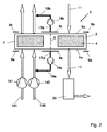
- FIG. 2 shows an alternative embodiment of the invention.
- the above statements apply to the embodiment of FIG. 1 analogous.
- the main difference to the embodiment of FIG. 1 is given in that the rotor 2 is flowed through on its left side by two separate gas flow streams 100 and 101 in the same direction, which are respectively heated during their flow through the rotor.
- the gas volume flow 100 may, for example, be a secondary air volume flow and the gas volume flow 101 may be, for example, a primary air volume flow.
- These gas flow rates 100 and 101 serve different uses in a power plant. Notwithstanding the representation in which the two gas volume flows 100 and 101 flow through the rotor 2 side by side, they can flow through the rotor at different locations, relative to the rotor cross-section.
Landscapes
- Engineering & Computer Science (AREA)
- Physics & Mathematics (AREA)
- Thermal Sciences (AREA)
- Mechanical Engineering (AREA)
- General Engineering & Computer Science (AREA)
- Heat-Exchange Devices With Radiators And Conduit Assemblies (AREA)
- Air Supply (AREA)
- Applications Or Details Of Rotary Compressors (AREA)
- Structures Of Non-Positive Displacement Pumps (AREA)
Priority Applications (7)
| Application Number | Priority Date | Filing Date | Title |
|---|---|---|---|
| EP08021916A EP2199724B1 (de) | 2008-12-17 | 2008-12-17 | Verfahren zum Betrieb eines regenerativen Wärmetauschers und regenerativer Wärmetauscher mit verbessertem Wirkungsgrad |
| SI200830803T SI2199724T1 (sl) | 2008-12-17 | 2008-12-17 | Postopek za delovanje regenerativnega prenosnika toplote in regenerativni prenosnik toplote z izboljšanim izkoristkom |
| PL08021916T PL2199724T3 (pl) | 2008-12-17 | 2008-12-17 | Sposób eksploatacji regeneracyjnego wymiennika ciepła i regeneracyjny wymiennik ciepła z polepszonym współczynnikiem sprawności |
| ZA200908902A ZA200908902B (en) | 2008-12-17 | 2009-12-14 | Method for operating a regenerative heat exchanger and regenerative heat exchanger having improved efficiency |
| RU2009146920/06A RU2432540C2 (ru) | 2008-12-17 | 2009-12-16 | Способ работы регенеративного теплообменника и регенеративный теплообменник с повышенным кпд |
| US12/641,218 US20100163208A1 (en) | 2008-12-17 | 2009-12-17 | Method For Operating A Regenerative Heat Exchanger And Regenerative Heat Exchanger Having Improved Efficiency |
| HRP20120880AT HRP20120880T1 (hr) | 2008-12-17 | 2012-10-31 | Postupak za rad regenerativnog izmjenjivaäśa topline i regenerativni izmjenjivaäś topline s poboljšanom uäśinkovitosti |
Applications Claiming Priority (1)
| Application Number | Priority Date | Filing Date | Title |
|---|---|---|---|
| EP08021916A EP2199724B1 (de) | 2008-12-17 | 2008-12-17 | Verfahren zum Betrieb eines regenerativen Wärmetauschers und regenerativer Wärmetauscher mit verbessertem Wirkungsgrad |
Publications (2)
| Publication Number | Publication Date |
|---|---|
| EP2199724A1 EP2199724A1 (de) | 2010-06-23 |
| EP2199724B1 true EP2199724B1 (de) | 2012-08-15 |
Family
ID=40638070
Family Applications (1)
| Application Number | Title | Priority Date | Filing Date |
|---|---|---|---|
| EP08021916A Active EP2199724B1 (de) | 2008-12-17 | 2008-12-17 | Verfahren zum Betrieb eines regenerativen Wärmetauschers und regenerativer Wärmetauscher mit verbessertem Wirkungsgrad |
Country Status (7)
| Country | Link |
|---|---|
| US (1) | US20100163208A1 (pl) |
| EP (1) | EP2199724B1 (pl) |
| HR (1) | HRP20120880T1 (pl) |
| PL (1) | PL2199724T3 (pl) |
| RU (1) | RU2432540C2 (pl) |
| SI (1) | SI2199724T1 (pl) |
| ZA (1) | ZA200908902B (pl) |
Families Citing this family (9)
| Publication number | Priority date | Publication date | Assignee | Title |
|---|---|---|---|---|
| DE102011055678A1 (de) * | 2011-11-24 | 2013-05-29 | Technische Universität Darmstadt | Kalziniervorrichtung zur Abscheidung von Kohlendioxid aus einem Feststoff |
| JP5713884B2 (ja) * | 2011-12-22 | 2015-05-07 | アルヴォス テクノロジー リミテッドARVOS Technology Limited | 回転再生式熱交換器 |
| US9841242B2 (en) | 2013-06-21 | 2017-12-12 | General Electric Technology Gmbh | Method of air preheating for combustion power plant and systems comprising the same |
| DE102016011918B4 (de) * | 2016-10-05 | 2018-05-30 | Balcke-Dürr GmbH | Regenerativer Wärmetauscher |
| RU2716639C1 (ru) * | 2019-07-05 | 2020-03-13 | Федеральное государственное унитарное предприятие "Центральный ордена Трудового Красного Знамени научно-исследовательский автомобильный и автомоторный институт "НАМИ" (ФГУП "НАМИ") | Высокотемпературный вращающийся дисковый теплообменник |
| RU2716640C1 (ru) * | 2019-07-05 | 2020-03-13 | Федеральное государственное унитарное предприятие "Центральный ордена Трудового Красного Знамени научно-исследовательский автомобильный и автомоторный институт "НАМИ" (ФГУП "НАМИ") | Силиконовые уплотнения высокотемпературного вращающегося дискового теплообменника |
| RU2716638C1 (ru) * | 2019-07-05 | 2020-03-13 | Федеральное государственное унитарное предприятие "Центральный ордена Трудового Красного Знамени научно-исследовательский автомобильный и автомоторный институт "НАМИ" (ФГУП "НАМИ") | Способ предотвращения деформации высокотемпературного вращающегося дискового теплообменника |
| RU2716636C1 (ru) * | 2019-07-05 | 2020-03-13 | Федеральное государственное унитарное предприятие "Центральный ордена Трудового Красного Знамени научно-исследовательский автомобильный и автомоторный институт "НАМИ" (ФГУП "НАМИ") | Способ компенсации деформации высокотемпературного вращающегося дискового теплообменника |
| RU202881U1 (ru) * | 2020-08-11 | 2021-03-11 | Федеральное государственное унитарное предприятие "Центральный ордена Трудового Красного Знамени научно-исследовательский автомобильный и автомоторный институт "НАМИ" (ФГУП "НАМИ") | Устройство охлаждения каркаса роторного дискового теплообменника энергетической установки |
Family Cites Families (6)
| Publication number | Priority date | Publication date | Assignee | Title |
|---|---|---|---|---|
| GB676129A (en) | 1949-02-09 | 1952-07-23 | Ljungstroms Angturbin Ab | Improvements in regenerative preheaters of the rotary type |
| US2665120A (en) | 1950-08-09 | 1954-01-05 | Blomquist Uno Olof | Regenerative heat exchanger |
| DE2634653C2 (de) | 1976-08-02 | 1985-05-15 | Apparatebau Rothemühle Brandt + Kritzler GmbH, 5963 Wenden | Regenerativ-Wärmetauscher mit einer stationären Regenerationkammer |
| DE3437945A1 (de) | 1984-10-17 | 1986-04-17 | Kraftanlagen Ag, 6900 Heidelberg | Verfahren und einrichtung fuer ein unterbinden des uebertritts von leckgasstroemen aus dem sektor des waermetauschenden gasstromes hoeheren druckes in denjenigen niedrigeren druckes in umlaufenden regenerativ-waermetauschern mit relativ zu den anschlusskanaelen bewegter speichermasse |
| DE4013484C2 (de) | 1989-04-27 | 1998-04-30 | Rothemuehle Brandt Kritzler | Verfahren und Anlage zur Minderung von Schadgasemissionen bei Wärmekraftwerken |
| DE4230133A1 (de) | 1992-09-09 | 1994-03-10 | Rothemuehle Brandt Kritzler | Regenerativ-Wärmetauscher und Verfahren zum Betreiben des Wärmetauschers |
-
2008
- 2008-12-17 SI SI200830803T patent/SI2199724T1/sl unknown
- 2008-12-17 PL PL08021916T patent/PL2199724T3/pl unknown
- 2008-12-17 EP EP08021916A patent/EP2199724B1/de active Active
-
2009
- 2009-12-14 ZA ZA200908902A patent/ZA200908902B/en unknown
- 2009-12-16 RU RU2009146920/06A patent/RU2432540C2/ru active
- 2009-12-17 US US12/641,218 patent/US20100163208A1/en not_active Abandoned
-
2012
- 2012-10-31 HR HRP20120880AT patent/HRP20120880T1/hr unknown
Also Published As
| Publication number | Publication date |
|---|---|
| US20100163208A1 (en) | 2010-07-01 |
| EP2199724A1 (de) | 2010-06-23 |
| HRP20120880T1 (hr) | 2012-11-30 |
| PL2199724T3 (pl) | 2013-01-31 |
| RU2009146920A (ru) | 2011-06-27 |
| SI2199724T1 (sl) | 2012-12-31 |
| ZA200908902B (en) | 2010-09-29 |
| RU2432540C2 (ru) | 2011-10-27 |
Similar Documents
| Publication | Publication Date | Title |
|---|---|---|
| EP2199724B1 (de) | Verfahren zum Betrieb eines regenerativen Wärmetauschers und regenerativer Wärmetauscher mit verbessertem Wirkungsgrad | |
| DE102012109878B4 (de) | Trockner für eine textile Warenbahn | |
| DE102009028354A1 (de) | Gasführungssystem für eine Peripherie einer Brennkraftmaschine zur Führung von Gas der Brennkraftmaschine, Brennkraftmaschine und Verfahren zum Betrieb der Brennkraftmaschine | |
| EP2324285B1 (de) | Abhitzedampferzeuger | |
| WO2013127924A2 (de) | Gasturbinenanlage mit abgasrezirkulation | |
| EP0666412A1 (de) | Verfahren zur Kühlung von Kühlluft für eine Gasturbine | |
| DE102013103298A1 (de) | Verfahren zum Betrieb eines Festbrennstoffheizkessels | |
| EP2622282B1 (de) | Receiver für solarenergiegewinnungsanlagen | |
| EP1660812B1 (de) | Durchlaufdampferzeuger sowie verfahren zum betreiben des durchlaufdampferzeugers | |
| DE102006060472B4 (de) | Verfahren zum Betreiben einer Dampfkraftanlage mit einem kohlegefeuerten Dampferzeuger sowie eine Dampfkraftanlage | |
| DE102008037762A1 (de) | Gliederheizkessel aus Gusseisen oder Aluminium | |
| WO2004072544A1 (de) | Luftkühler für kraftwerksanlagen sowie anwendung eines solchen luftkühlers | |
| EP0797063A2 (de) | Verfahren zum Beheizen eines Industrieofens und Regenerator-Brenner-Modulsystem hierfür | |
| DE102009015260B4 (de) | Vorrichtung zur Phasenseparation eines Mehrphasen-Fluidstroms, Dampfturbinenanlage mit einer derartigen Vorrichtung und zugehöriges Betriebsverfahren | |
| DE19926949B4 (de) | Kühlungsanordnung für Schaufeln einer Gasturbine | |
| WO2005028956A1 (de) | Durchlaufdampferzeuger in liegender bauweise und verfahren zum betreiben des durchlaufdampferzeugers | |
| EP2174060B1 (de) | Dampferzeuger | |
| DE2441706A1 (de) | Heizkessel mit gusseisernen gerippten rohren | |
| DE69103606T2 (de) | Isolierung eines luftgekühlten Dampfkondensators mit Vakuum. | |
| DE102009035674A1 (de) | Wärmetauscher, Wärmetauschersystem | |
| DE102010041130A1 (de) | Halterungsvorrichtung zum Haltern von Empfängermodulen für konzentrierte Solarstrahlung in einem solarthermischen Kraftwerk und solarthermisches Kraftwerk | |
| DE4029151C1 (pl) | ||
| DE2601181C2 (de) | Vorrichtung zur thermischen Reinigungsbehandlung eines Abgases | |
| DE202015101272U1 (de) | Mobile Feuerungsanlage | |
| EP2472180A1 (de) | Brennervorrichtung |
Legal Events
| Date | Code | Title | Description |
|---|---|---|---|
| PUAI | Public reference made under article 153(3) epc to a published international application that has entered the european phase |
Free format text: ORIGINAL CODE: 0009012 |
|
| 17P | Request for examination filed |
Effective date: 20090813 |
|
| AK | Designated contracting states |
Kind code of ref document: A1 Designated state(s): AT BE BG CH CY CZ DE DK EE ES FI FR GB GR HR HU IE IS IT LI LT LU LV MC MT NL NO PL PT RO SE SI SK TR |
|
| AX | Request for extension of the european patent |
Extension state: AL BA MK RS |
|
| AKX | Designation fees paid |
Designated state(s): AT BE BG CH CY CZ DE DK EE ES FI FR GB GR HR HU IE IS IT LI LT LU LV MC MT NL NO PL PT RO SE SI SK TR |
|
| GRAP | Despatch of communication of intention to grant a patent |
Free format text: ORIGINAL CODE: EPIDOSNIGR1 |
|
| GRAS | Grant fee paid |
Free format text: ORIGINAL CODE: EPIDOSNIGR3 |
|
| GRAA | (expected) grant |
Free format text: ORIGINAL CODE: 0009210 |
|
| AK | Designated contracting states |
Kind code of ref document: B1 Designated state(s): AT BE BG CH CY CZ DE DK EE ES FI FR GB GR HR HU IE IS IT LI LT LU LV MC MT NL NO PL PT RO SE SI SK TR |
|
| REG | Reference to a national code |
Ref country code: GB Ref legal event code: FG4D Free format text: NOT ENGLISH Ref country code: CH Ref legal event code: EP Ref country code: AT Ref legal event code: REF Ref document number: 571059 Country of ref document: AT Kind code of ref document: T Effective date: 20120815 |
|
| REG | Reference to a national code |
Ref country code: DE Ref legal event code: R082 Ref document number: 502008007939 Country of ref document: DE Representative=s name: PATENTANWAELTE LANG & TOMERIUS, DE Ref country code: DE Ref legal event code: R082 Ref document number: 502008007939 Country of ref document: DE Representative=s name: LANG & TOMERIUS PATENTANWALTSPARTNERSCHFT MBB, DE Ref country code: DE Ref legal event code: R082 Ref document number: 502008007939 Country of ref document: DE Representative=s name: LANG & TOMERIUS PATENTANWALTSPARTNERSCHAFT MBB, DE |
|
| REG | Reference to a national code |
Ref country code: IE Ref legal event code: FG4D Free format text: LANGUAGE OF EP DOCUMENT: GERMAN |
|
| REG | Reference to a national code |
Ref country code: DE Ref legal event code: R096 Ref document number: 502008007939 Country of ref document: DE Effective date: 20121011 |
|
| REG | Reference to a national code |
Ref country code: HR Ref legal event code: TUEP Ref document number: P20120880 Country of ref document: HR |
|
| REG | Reference to a national code |
Ref country code: RO Ref legal event code: EPE |
|
| REG | Reference to a national code |
Ref country code: NL Ref legal event code: T3 |
|
| REG | Reference to a national code |
Ref country code: HR Ref legal event code: T1PR Ref document number: P20120880 Country of ref document: HR |
|
| REG | Reference to a national code |
Ref country code: GR Ref legal event code: EP Ref document number: 20120402184 Country of ref document: GR Effective date: 20121122 |
|
| PG25 | Lapsed in a contracting state [announced via postgrant information from national office to epo] |
Ref country code: IS Free format text: LAPSE BECAUSE OF FAILURE TO SUBMIT A TRANSLATION OF THE DESCRIPTION OR TO PAY THE FEE WITHIN THE PRESCRIBED TIME-LIMIT Effective date: 20121215 Ref country code: CY Free format text: LAPSE BECAUSE OF FAILURE TO SUBMIT A TRANSLATION OF THE DESCRIPTION OR TO PAY THE FEE WITHIN THE PRESCRIBED TIME-LIMIT Effective date: 20120815 Ref country code: LT Free format text: LAPSE BECAUSE OF FAILURE TO SUBMIT A TRANSLATION OF THE DESCRIPTION OR TO PAY THE FEE WITHIN THE PRESCRIBED TIME-LIMIT Effective date: 20120815 Ref country code: NO Free format text: LAPSE BECAUSE OF FAILURE TO SUBMIT A TRANSLATION OF THE DESCRIPTION OR TO PAY THE FEE WITHIN THE PRESCRIBED TIME-LIMIT Effective date: 20121115 Ref country code: FI Free format text: LAPSE BECAUSE OF FAILURE TO SUBMIT A TRANSLATION OF THE DESCRIPTION OR TO PAY THE FEE WITHIN THE PRESCRIBED TIME-LIMIT Effective date: 20120815 |
|
| REG | Reference to a national code |
Ref country code: PL Ref legal event code: T3 |
|
| REG | Reference to a national code |
Ref country code: SK Ref legal event code: T3 Ref document number: E 12884 Country of ref document: SK |
|
| PG25 | Lapsed in a contracting state [announced via postgrant information from national office to epo] |
Ref country code: LV Free format text: LAPSE BECAUSE OF FAILURE TO SUBMIT A TRANSLATION OF THE DESCRIPTION OR TO PAY THE FEE WITHIN THE PRESCRIBED TIME-LIMIT Effective date: 20120815 Ref country code: SE Free format text: LAPSE BECAUSE OF FAILURE TO SUBMIT A TRANSLATION OF THE DESCRIPTION OR TO PAY THE FEE WITHIN THE PRESCRIBED TIME-LIMIT Effective date: 20120815 Ref country code: PT Free format text: LAPSE BECAUSE OF FAILURE TO SUBMIT A TRANSLATION OF THE DESCRIPTION OR TO PAY THE FEE WITHIN THE PRESCRIBED TIME-LIMIT Effective date: 20121217 |
|
| PG25 | Lapsed in a contracting state [announced via postgrant information from national office to epo] |
Ref country code: EE Free format text: LAPSE BECAUSE OF FAILURE TO SUBMIT A TRANSLATION OF THE DESCRIPTION OR TO PAY THE FEE WITHIN THE PRESCRIBED TIME-LIMIT Effective date: 20120815 Ref country code: CZ Free format text: LAPSE BECAUSE OF FAILURE TO SUBMIT A TRANSLATION OF THE DESCRIPTION OR TO PAY THE FEE WITHIN THE PRESCRIBED TIME-LIMIT Effective date: 20120815 Ref country code: DK Free format text: LAPSE BECAUSE OF FAILURE TO SUBMIT A TRANSLATION OF THE DESCRIPTION OR TO PAY THE FEE WITHIN THE PRESCRIBED TIME-LIMIT Effective date: 20120815 Ref country code: ES Free format text: LAPSE BECAUSE OF FAILURE TO SUBMIT A TRANSLATION OF THE DESCRIPTION OR TO PAY THE FEE WITHIN THE PRESCRIBED TIME-LIMIT Effective date: 20121126 |
|
| PLBE | No opposition filed within time limit |
Free format text: ORIGINAL CODE: 0009261 |
|
| STAA | Information on the status of an ep patent application or granted ep patent |
Free format text: STATUS: NO OPPOSITION FILED WITHIN TIME LIMIT |
|
| BERE | Be: lapsed |
Owner name: BALCKE-DURR G.M.B.H. Effective date: 20121231 |
|
| 26N | No opposition filed |
Effective date: 20130516 |
|
| PG25 | Lapsed in a contracting state [announced via postgrant information from national office to epo] |
Ref country code: MC Free format text: LAPSE BECAUSE OF NON-PAYMENT OF DUE FEES Effective date: 20121231 |
|
| REG | Reference to a national code |
Ref country code: CH Ref legal event code: PL |
|
| REG | Reference to a national code |
Ref country code: DE Ref legal event code: R097 Ref document number: 502008007939 Country of ref document: DE Effective date: 20130516 |
|
| REG | Reference to a national code |
Ref country code: FR Ref legal event code: ST Effective date: 20130830 |
|
| PG25 | Lapsed in a contracting state [announced via postgrant information from national office to epo] |
Ref country code: BE Free format text: LAPSE BECAUSE OF NON-PAYMENT OF DUE FEES Effective date: 20121231 |
|
| REG | Reference to a national code |
Ref country code: HU Ref legal event code: AG4A Ref document number: E016835 Country of ref document: HU |
|
| PG25 | Lapsed in a contracting state [announced via postgrant information from national office to epo] |
Ref country code: CH Free format text: LAPSE BECAUSE OF NON-PAYMENT OF DUE FEES Effective date: 20121231 Ref country code: LI Free format text: LAPSE BECAUSE OF NON-PAYMENT OF DUE FEES Effective date: 20121231 |
|
| PG25 | Lapsed in a contracting state [announced via postgrant information from national office to epo] |
Ref country code: FR Free format text: LAPSE BECAUSE OF NON-PAYMENT OF DUE FEES Effective date: 20130102 Ref country code: MT Free format text: LAPSE BECAUSE OF FAILURE TO SUBMIT A TRANSLATION OF THE DESCRIPTION OR TO PAY THE FEE WITHIN THE PRESCRIBED TIME-LIMIT Effective date: 20120815 |
|
| PG25 | Lapsed in a contracting state [announced via postgrant information from national office to epo] |
Ref country code: LU Free format text: LAPSE BECAUSE OF NON-PAYMENT OF DUE FEES Effective date: 20121217 |
|
| REG | Reference to a national code |
Ref country code: HR Ref legal event code: ODRP Ref document number: P20120880 Country of ref document: HR Payment date: 20141218 Year of fee payment: 7 |
|
| PGFP | Annual fee paid to national office [announced via postgrant information from national office to epo] |
Ref country code: SK Payment date: 20141218 Year of fee payment: 7 Ref country code: RO Payment date: 20141219 Year of fee payment: 7 |
|
| REG | Reference to a national code |
Ref country code: AT Ref legal event code: MM01 Ref document number: 571059 Country of ref document: AT Kind code of ref document: T Effective date: 20131217 |
|
| PGFP | Annual fee paid to national office [announced via postgrant information from national office to epo] |
Ref country code: SI Payment date: 20141219 Year of fee payment: 7 Ref country code: HR Payment date: 20141218 Year of fee payment: 7 |
|
| PGFP | Annual fee paid to national office [announced via postgrant information from national office to epo] |
Ref country code: BG Payment date: 20141218 Year of fee payment: 7 |
|
| PG25 | Lapsed in a contracting state [announced via postgrant information from national office to epo] |
Ref country code: AT Free format text: LAPSE BECAUSE OF NON-PAYMENT OF DUE FEES Effective date: 20131217 |
|
| REG | Reference to a national code |
Ref country code: HR Ref legal event code: PBON Ref document number: P20120880 Country of ref document: HR Effective date: 20151217 |
|
| PG25 | Lapsed in a contracting state [announced via postgrant information from national office to epo] |
Ref country code: RO Free format text: LAPSE BECAUSE OF NON-PAYMENT OF DUE FEES Effective date: 20151217 |
|
| REG | Reference to a national code |
Ref country code: SK Ref legal event code: MM4A Ref document number: E 12884 Country of ref document: SK Effective date: 20151217 |
|
| REG | Reference to a national code |
Ref country code: SI Ref legal event code: KO00 Effective date: 20160830 |
|
| PG25 | Lapsed in a contracting state [announced via postgrant information from national office to epo] |
Ref country code: BG Free format text: LAPSE BECAUSE OF NON-PAYMENT OF DUE FEES Effective date: 20160930 |
|
| PG25 | Lapsed in a contracting state [announced via postgrant information from national office to epo] |
Ref country code: SK Free format text: LAPSE BECAUSE OF NON-PAYMENT OF DUE FEES Effective date: 20151217 Ref country code: HR Free format text: LAPSE BECAUSE OF NON-PAYMENT OF DUE FEES Effective date: 20151217 Ref country code: SI Free format text: LAPSE BECAUSE OF NON-PAYMENT OF DUE FEES Effective date: 20151218 |
|
| PG25 | Lapsed in a contracting state [announced via postgrant information from national office to epo] |
Ref country code: IT Free format text: LAPSE BECAUSE OF NON-PAYMENT OF DUE FEES Effective date: 20151217 |
|
| PG25 | Lapsed in a contracting state [announced via postgrant information from national office to epo] |
Ref country code: IT Free format text: LAPSE BECAUSE OF NON-PAYMENT OF DUE FEES Effective date: 20151217 |
|
| PGFP | Annual fee paid to national office [announced via postgrant information from national office to epo] |
Ref country code: IT Payment date: 20161222 Year of fee payment: 9 |
|
| PGRI | Patent reinstated in contracting state [announced from national office to epo] |
Ref country code: IT Effective date: 20170710 |
|
| PG25 | Lapsed in a contracting state [announced via postgrant information from national office to epo] |
Ref country code: IT Free format text: LAPSE BECAUSE OF NON-PAYMENT OF DUE FEES Effective date: 20171217 |
|
| REG | Reference to a national code |
Ref country code: DE Ref legal event code: R081 Ref document number: 502008007939 Country of ref document: DE Owner name: HOWDEN ROTHEMUEHLE GMBH, DE Free format text: FORMER OWNER: BALCKE DUERR GMBH, 40882 RATINGEN, DE Ref country code: DE Ref legal event code: R082 Ref document number: 502008007939 Country of ref document: DE Representative=s name: LANG & TOMERIUS PATENTANWALTSPARTNERSCHAFT MBB, DE Ref country code: DE Ref legal event code: R081 Ref document number: 502008007939 Country of ref document: DE Owner name: BALCKE-DUERR ROTHEMUEHLE GMBH, DE Free format text: FORMER OWNER: BALCKE DUERR GMBH, 40882 RATINGEN, DE |
|
| REG | Reference to a national code |
Ref country code: NL Ref legal event code: PD Owner name: BALCKE-DUERR ROTHEMUEHLE GMBH; DE Free format text: DETAILS ASSIGNMENT: CHANGE OF OWNER(S), ASSIGNMENT; FORMER OWNER NAME: BALCKE-DUERR GMBH Effective date: 20191205 |
|
| REG | Reference to a national code |
Ref country code: GB Ref legal event code: 732E Free format text: REGISTERED BETWEEN 20191212 AND 20191218 |
|
| REG | Reference to a national code |
Ref country code: HU Ref legal event code: FH1C Free format text: FORMER REPRESENTATIVE(S): SIPOS JOZSEF, DANUBIA SZABADALMI ES JOGI IRODA KFT., HU Representative=s name: DANUBIA SZABADALMI ES JOGI IRODA KFT., HU Ref country code: HU Ref legal event code: GB9C Owner name: BALCKE-DUERR ROTHEMUEHLE GMBH, DE Free format text: FORMER OWNER(S): BALCKE-DUERR GMBH, DE |
|
| REG | Reference to a national code |
Ref country code: NL Ref legal event code: HC Owner name: HOWDEN ROTHEMUEHLE GMBH; DE Free format text: DETAILS ASSIGNMENT: CHANGE OF OWNER(S), CHANGE OF OWNER(S) NAME; FORMER OWNER NAME: BALCKE-DUERR ROTHEMUEHLE GMBH Effective date: 20230102 |
|
| REG | Reference to a national code |
Ref country code: DE Ref legal event code: R081 Ref document number: 502008007939 Country of ref document: DE Owner name: HOWDEN ROTHEMUEHLE GMBH, DE Free format text: FORMER OWNER: BALCKE-DUERR ROTHEMUEHLE GMBH, 57462 OLPE, DE |
|
| REG | Reference to a national code |
Ref country code: HU Ref legal event code: HC9C Owner name: HOWDEN ROTHEMUEHLE GMBH, DE Free format text: FORMER OWNER(S): BALCKE-DUERR GMBH, DE; BALCKE-DUERR ROTHEMUEHLE GMBH, DE |
|
| P01 | Opt-out of the competence of the unified patent court (upc) registered |
Effective date: 20230531 |
|
| REG | Reference to a national code |
Ref country code: DE Ref legal event code: R082 Ref document number: 502008007939 Country of ref document: DE Representative=s name: MURGITROYD GERMANY PATENTANWALTSGESELLSCHAFT M, DE |
|
| PGFP | Annual fee paid to national office [announced via postgrant information from national office to epo] |
Ref country code: PL Payment date: 20241203 Year of fee payment: 17 Ref country code: NL Payment date: 20241226 Year of fee payment: 17 Ref country code: GR Payment date: 20241230 Year of fee payment: 17 |
|
| PGFP | Annual fee paid to national office [announced via postgrant information from national office to epo] |
Ref country code: GB Payment date: 20241227 Year of fee payment: 17 |
|
| PGFP | Annual fee paid to national office [announced via postgrant information from national office to epo] |
Ref country code: HU Payment date: 20241209 Year of fee payment: 17 |
|
| PGFP | Annual fee paid to national office [announced via postgrant information from national office to epo] |
Ref country code: IE Payment date: 20241227 Year of fee payment: 17 |
|
| PGFP | Annual fee paid to national office [announced via postgrant information from national office to epo] |
Ref country code: DE Payment date: 20241227 Year of fee payment: 17 |
|
| PGFP | Annual fee paid to national office [announced via postgrant information from national office to epo] |
Ref country code: TR Payment date: 20241210 Year of fee payment: 17 |