EP2199238A2 - Bilderstellungsvorrichtung und Papierzuführvorrichtung davon - Google Patents
Bilderstellungsvorrichtung und Papierzuführvorrichtung davon Download PDFInfo
- Publication number
- EP2199238A2 EP2199238A2 EP09177415A EP09177415A EP2199238A2 EP 2199238 A2 EP2199238 A2 EP 2199238A2 EP 09177415 A EP09177415 A EP 09177415A EP 09177415 A EP09177415 A EP 09177415A EP 2199238 A2 EP2199238 A2 EP 2199238A2
- Authority
- EP
- European Patent Office
- Prior art keywords
- sheet feeding
- pickup roller
- image forming
- forming apparatus
- paper
- Prior art date
- Legal status (The legal status is an assumption and is not a legal conclusion. Google has not performed a legal analysis and makes no representation as to the accuracy of the status listed.)
- Granted
Links
Images




Classifications
-
- B—PERFORMING OPERATIONS; TRANSPORTING
- B41—PRINTING; LINING MACHINES; TYPEWRITERS; STAMPS
- B41J—TYPEWRITERS; SELECTIVE PRINTING MECHANISMS, i.e. MECHANISMS PRINTING OTHERWISE THAN FROM A FORME; CORRECTION OF TYPOGRAPHICAL ERRORS
- B41J11/00—Devices or arrangements of selective printing mechanisms, e.g. ink-jet printers or thermal printers, for supporting or handling copy material in sheet or web form
- B41J11/006—Means for preventing paper jams or for facilitating their removal
-
- B—PERFORMING OPERATIONS; TRANSPORTING
- B65—CONVEYING; PACKING; STORING; HANDLING THIN OR FILAMENTARY MATERIAL
- B65H—HANDLING THIN OR FILAMENTARY MATERIAL, e.g. SHEETS, WEBS, CABLES
- B65H3/00—Separating articles from piles
- B65H3/46—Supplementary devices or measures to assist separation or prevent double feed
- B65H3/52—Friction retainers acting on under or rear side of article being separated
- B65H3/5207—Non-driven retainers, e.g. movable retainers being moved by the motion of the article
- B65H3/5215—Non-driven retainers, e.g. movable retainers being moved by the motion of the article the retainers positioned under articles separated from the top of the pile
- B65H3/5223—Retainers of the pad-type, e.g. friction pads
-
- B—PERFORMING OPERATIONS; TRANSPORTING
- B65—CONVEYING; PACKING; STORING; HANDLING THIN OR FILAMENTARY MATERIAL
- B65H—HANDLING THIN OR FILAMENTARY MATERIAL, e.g. SHEETS, WEBS, CABLES
- B65H2405/00—Parts for holding the handled material
- B65H2405/30—Other features of supports for sheets
- B65H2405/31—Supports for sheets fully removable from the handling machine, e.g. cassette
-
- B—PERFORMING OPERATIONS; TRANSPORTING
- B65—CONVEYING; PACKING; STORING; HANDLING THIN OR FILAMENTARY MATERIAL
- B65H—HANDLING THIN OR FILAMENTARY MATERIAL, e.g. SHEETS, WEBS, CABLES
- B65H2601/00—Problem to be solved or advantage achieved
- B65H2601/10—Ensuring correct operation
- B65H2601/11—Clearing faulty handling, e.g. jams
-
- B—PERFORMING OPERATIONS; TRANSPORTING
- B65—CONVEYING; PACKING; STORING; HANDLING THIN OR FILAMENTARY MATERIAL
- B65H—HANDLING THIN OR FILAMENTARY MATERIAL, e.g. SHEETS, WEBS, CABLES
- B65H2801/00—Application field
- B65H2801/03—Image reproduction devices
- B65H2801/06—Office-type machines, e.g. photocopiers
Definitions
- the present disclosure relates generally to an image forming apparatus, particularly to an image forming apparatus having an improved paper feeding performance.
- image forming apparatuses refer to apparatuses forming images on printing media, and may include, e.g., a printer, a copier, a facsimile and a multifunction apparatus that combines some functions of the afore-mentioned.
- the printing medium may be referred to as 'paper' in the descriptions below, which should not, however, be construed as limiting the printing medium to paper.
- the image forming apparatus is equipped with a paper feeding device that supplies paper to a printing device also included in the apparatus.
- the paper received in the paper feeding device is picked up by a pickup unit, and is fed to the printing device along a predetermined path.
- the paper feeding device may include a multi-sheet feeding prevention unit to prevent simultaneous feeding of multiple sheets of paper.
- the multi-sheet feeding prevention unit is typically disposed to face the pickup unit and to bias the paper toward the pickup unit.
- the paper While the image forming apparatus is performing a printing operation, the paper may be caught between the pickup unit and the multi-sheet feeding prevention unit, resulting in a 'paper jam.' When such a paper jam occurs, it may be difficult for a user to remove the jammed paper because of the pressure exerted between the pickup unit and the multi-sheet feeding prevention unit. If the user forcibly pulls on the paper, the paper, the pickup unit, and/or the multi-sheet feeding prevention unit may become damaged. A paper feeding device capable of convenient removal of jammed paper is thus desirable.
- an image forming apparatus may be provided to comprise a main body, a printing media feeding cassette, a pickup roller and a multi-sheet feeding prevention unit.
- the main body may be configured to support a printing device received therein.
- the printing media feeding cassette may be detachably mounted to the main body, and may be configured to support one or more printing media receive therein.
- the pickup roller may be configured to pick up a printing medium from the printing media feeding cassette.
- the multi-sheet feeding prevention unit may be configured to impart a pressing force on the pickup roller when the multi-sheet feeding prevention unit is in a contact position and to release the pressing force to the pickup roller when the multi-sheet feeding prevention unit is in a releasing position.
- the multi-sheet feeding prevention unit may be in the contact position when the printing media feeding caste is mounted to the main body, and may be in the releasing position when the printing media feeding cassette is at least partially detached from the main body.
- the multi-sheet feeding prevention unit may comprise a multi-sheet feeding prevention member facing the pickup roller and a holder supporting the multi-sheet feeding prevention member.
- the printing media feeding cassette when it is mounted in the main body, may press against the holder so that the multi-sheet feeding prevention member is in a pressing contact with the pickup roller.
- the multi-sheet feeding prevention unit may further comprise an elastic member to elastically bias the holder in such a manner elastically biasing the multi-sheet feeding prevention member toward the pickup roller.
- One end of the elastic member may be supported by the holder while the other end of the elastic member may be supported by the printing media feeding cassette.
- the holder may comprise a rotating shaft, a supporting arm and an operating arm.
- the supporting arm may extend from the rotating shaft, and may be configured to support the multi-sheet feeding prevention member.
- the operating arm may extend from the rotating shaft, and may be configured to face the printing media feeding cassette.
- the image forming apparatus may further comprise an elastic member disposed between the operating arm and the printing media feeding cassette.
- the multi-sheet feeding prevention unit may further comprise a cap coupled to the operating arm and configured to receive the elastic member.
- the image forming apparatus may further comprise a guide frame having a guide surface by which the printing medium picked up by the pickup roller is guided along a paper feed path.
- the holder may be rotatably mounted to the guide frame.
- an image forming apparatus may be provided to comprise a printing media feeding cassette, a pickup roller and a multi-sheet feeding prevention unit.
- the printing media feeding cassette may have a paper receiving surface on which one or more sheets of paper are to be stacked.
- the pickup roller may be configured to pick up a paper from the printing media feeding cassette.
- the multi-sheet feeding prevention unit may be moveable between a contact position and a releasing position, and may have a multi-sheet feeding prevention member supported on an end thereof.
- the multi-sheet feeding prevention unit may be configured to be in the contact position when the multi-sheet feeding prevention unit is in an interfering contact with the printing media feeding cassette.
- the multi-sheet feeding prevention member may impart a first pressing force on the pickup roller when the multi-sheet feeding prevention unit is in the contact position.
- the multi-sheet feeding prevention unit may be configured to be in the releasing position when the multi-sheet feeding prevention unit is not in contact with the printing media feeding cassette.
- the multi-sheet feeding prevention member may impart a second pressing force less than the first pressing force on the pickup roller when the multi-sheet feeding prevention unit is in the releasing position.
- the multi-sheet feeding prevention member When the multi-sheet feeding prevention unit is in the releasing position, the multi-sheet feeding prevention member may not contact the pickup roller so that the second pressing force imparted on the pickup roller is zero.
- the multi-sheet feeding prevention unit may further comprise a holder and an elastic member.
- the holder may be rotatably disposed in the image forming apparatus, and may be configured to support the multi-sheet feeding prevention member.
- One end of the elastic member may be supported by the holder while the other end may be supported by the printing media feeding cassette.
- the holder may comprise a rotating shaft, a supporting arm and an operating arm.
- the supporting arm may extend from the rotating shaft in a first direction toward the pickup roller, and may support the multi-sheet feeding prevention member at one end thereof away from the rotating shaft.
- the operating arm may extend from the rotating shaft in a second direction away from the pickup roller, and may have a surface opposingly facing the printing media feeding cassette.
- the printing media feeding cassette may be configured to press against the operating arm of the holder so as to bias the multi-sheet feeding prevention member toward the pickup roller.
- the image forming apparatus may further comprise a guide frame having a guide surface by which the printing medium picked up by the pickup roller is guided along a paper feed path defined within the image forming apparatus.
- the holder may be rotatably supported on the guide frame.
- a printing media feeding device may be useable in an image forming apparatus that includes a printing media feeding cassette in which to receive one or more printing media, and may comprise a pickup roller and a multi-sheet feeding prevention unit.
- the pickup roller may be configured to pickup up a printing medium from the printing media feeding cassette.
- the multi-sheet feeding prevention unit may have a multi-sheet feeding prevention member opposingly facing the pickup roller.
- the multi-sheet feeding prevention unit may be configured to rotate about a rotational shaft in cooperation with the printing media feeding cassette of the image forming apparatus.
- the multi-sheet feeding prevention unit may be rotatable about the rotational shaft between a pressing position and a releasing position.
- the multi-sheet feeding prevention unit may be in the pressing position when the multi-sheet feeding prevention unit is in an interfering contact with the printing media cassette installed in the image forming apparatus.
- the multi-sheet feeding prevention unit may be in the releasing position when the multi-sheet feeding prevention unit is not in contact with the printing media cassette.
- the multi-sheet feeding prevention member may impart a first pressing force on the pickup roller when the multi-sheet feeding prevention unit is in the pressing position.
- the multi-sheet feeding prevention member may impart a second pressing force less than the first pressing force on the pickup roller when the multi-sheet feeding prevention unit is in the releasing position.
- the multi-sheet feeding prevention unit may further comprise a supporting arm and an operating arm.
- the supporting arm may extend from the rotational shaft in a first direction toward the pickup roller, and may support the multi-sheet feeding prevention member at one end thereof away from the rotational shaft.
- the operating arm may extend from the rotational shaft in a second direction away from the pickup roller, and may have a surface opposingly facing the printing media feeding cassette.
- the multi-sheet feeding prevention unit may further comprise an elastic member disposed between the printing media feeding cassette and the operating arm.
- the elastic member may elastically bias the multi-sheet feeding prevention member toward the pickup roller when the multi-sheet feeding prevention unit is in a pressing contact with the printing media feeding cassette.
- the multi-sheet feeding prevention member When the printing media feeding cassette is in pressing contact with the operating arm of the multi-sheet feeding prevention unit, the multi-sheet feeding prevention member may impart a first pressing force on the pickup roller. When the operating arm of the multi-sheet feeding prevention unit is not in contact with the printing media cassette, the multi-sheet feeding prevention member may impart a second pressing force less than the first pressing force on the pickup roller.
- FIG. 1 is a view showing the structure of an image forming apparatus according to an embodiment of the present disclosure.
- an image forming apparatus 1 may comprise a main body 10, a paper feeding device 20, a printing device 30 and a paper discharging device 100.
- the main body 10 may define the overall external appearance of the image forming apparatus, and may support various components therein.
- the paper feeding device 20 supplies paper to the printing device 30.
- the paper feeding device 20 will be described in greater detail later.
- the printing device 30 prints images on the paper fed from the paper feeding device 20.
- an electrophotographic type image forming apparatus is described below.
- the printing device 30 of an electrophotographic type image forming apparatus may comprise photosensitive mediums 40K, 40C 40M and 40Y, charging devices 50, a laser scanning unit 60, a developing unit 70, a transfer unit 80 and a fixing unit 90.
- the charging devices 50 may uniformly electrify the surface of the respective corresponding one of the photosensitive mediums 40K, 40C 40M and 40Y.
- the laser scanning unit 60 may scan the electrified surfaces of the photosensitive mediums 40K, 40C 40M and 40Y with laser beams corresponding to the image data, thereby forming electrostatic latent images on the surfaces of the photosensitive mediums 40K, 40C 40M and 40Y.
- the developing unit 70 may supply toner to the electrostatic latent images formed on the photosensitive mediums 40K, 40C 40M and 40Y, thereby developing the electrostatic latent images into visible toner images.
- the developing unit 70 may be constituted by four developing devices 70K, 70C 70M and 70Y, storing black, cyan, magenta and yellow toners, respectively.
- Each of the developing devices 70K, 70C 70M and 70Y may include a supplying roller 71 and a developing roller 72.
- the supplying rollers 71 supply the toner to the corresponding developing roller 72.
- the developing rollers 72 in turn supply the toner respectively to the photosensitive mediums 40K, 40C, 40M and 40Y to develop the electrostatic latent images into the visible toner images.
- the transfer unit 80 may comprise a transfer belt 81, first transfer rollers 82, a second transfer roller 83 and supporting rollers 84.
- the transfer rollers 81 may rotates while pressing against the corresponding one of the photosensitive mediums 40K, 40C 40M and 40Y.
- the transfer belt 81 may rotate while being supported by the supporting rollers 84 around a loop path that includes a portion in which the transfer belt 81 is interposed between the transfer rollers 81 and the photosensitive mediums 40K, 40C 40M and 40Y.
- the visible images formed on the photosensitive mediums 40K, 40C 40M and 40Y may be transferred to the transfer belt 81 by the first transfer rollers 82 in an overlapping manner.
- the overlapped images on the transfer belt 81 may be transferred onto a paper fed from the paper feeding device 20 that pass between the second transfer roller 83 and the transfer belt 81.
- the paper that has passed through the transfer unit 80 may subsequently be introduced into the fixing device 90, which may comprise a heating roller 91 and a pressing roller 92.
- the paper bearing thereon the transferred toner images may be made to pass between the heating roller 91 and the pressing roller 92, during which the toner images are fixed to the paper by heat and pressure.
- the paper may be guided to the paper discharging unit 100, and may be discharged to the outside by a discharging roller 101.
- FIG. 2 is a partially enlarged view of the circled portion of FIG. 1 .
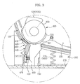
- FIG. 3 shows the portion shown in FIG. 2 , but with the paper feeding cassette separated from the main body 10.
- FIG. 4 is a perspective view showing the structure of the paper feeding device according to an embodiment. In FIG. 4 , a pickup guide and the paper feeding cassette are separately illustrated.
- the paper feeding device 20 may comprise the paper feeding cassette 200, a pickup roller 300 and a multi-sheet feeding prevention unit 400.
- the paper feeding cassette 200 is structured to receive papers S, and may be detachably mounted to the main body 10.
- the pickup roller 300 may pick up the paper S from the paper feeding cassette 200, and may feed the picked up paper S to a feeding roller 110 (shown in FIG. 1 ).
- a guide frame 120 may further be provided in front of the paper feeding cassette 200.
- the guide frame 120 may comprise a guide surface 122 having a plurality of ribs 121 extending along the paper feeding direction so as to guide the paper picked up by the pickup roller 300 to the feeding roller 110.
- the feeding roller 110 may align the leading end of the paper being fed from the pickup roller 300, and may feed the paper further along the paper path toward the second transfer roller 83.
- the multi-sheet feeding prevention unit 400 may press against the pickup roller 300 so that the pickup roller 300 can pick up the paper one sheet at a time. To that end, the multi-sheet feeding prevention unit 400 may be disposed at a lower part of the pickup roller 300, and may press the rear side of the paper while the paper is being picked up, thereby reducing simultaneous pickup of multiple sheets, that is, a multi-sheet feeding.
- the paper feeding cassette 200 may comprise a cassette body 210 and a knock-up plate 220 supporting the received paper S.
- the knock-up plate 220 may be pivotably mounted to the cassette body 210. More particularly, the knock-up plate 220 may be connected to the cassette body 210 through a hinge shaft 221 (see FIG. 4 ) formed at the rear end thereof, therefore allowing the leading end of the knock-up plate 220 to pivot up and down.
- the pickup roller 300 may be disposed above the leading end of the knock-up plate 220.
- the pickup roller 300 may be connected to a pickup shaft 310 rotatably mounted to the main body 10.
- the pickup shaft 310 may be rotated by a rotational force received from a driving motor (not shown) mounted in the main body 10.
- the pickup roller 300 may comprise a rotating pickup member 320 configured to contact the paper stacked on the knock-up plate 220 and a pair of idle rollers 330 mounted at the sides of the rotating pickup member 320 that may rotate idly.
- the rotating pickup member 320 may include a contact part 321 contacting the paper only in a predetermined section during the rotation of the rotating pickup member 320.
- the contact part 321 may protrude in the radial direction of the idle roller 330.
- the idle roller 330 may be separated from the paper.
- the contact part 321 is out of contact with the paper, the idle roller 330 may be in contact with the paper.
- the idle roller 330 presses the multi-sheet feeding prevention unit 400 with a predetermined pressure so that only the uppermost sheet of the paper may be picked up and fed from the knock-up plate 220.
- the paper feeding device 20 may comprise an elevating unit 500 to move the knock-up plate 220 up and down.
- the elevating unit 500 may comprise a spring 510 elastically biasing the knock-up plate 220 upward and a pair of cams 520 that may be connected to both sides of the pickup shaft 310, and which may rotate along with the pickup roller 300.
- Guide rollers 530 may be further formed at the sidewalls of the knock-up plate 220 at locations corresponding to the cams 520 so as to allow the cams 520 to press the knock-up plate 220 more efficiently.
- FIG. 5 is a perspective view showing the pickup guide, a portion of the paper feeding cassette and the multi-sheet feeding prevention unit of an image forming apparatus according to an embodiment of the present disclosure.
- the multi-sheet feeding prevention unit 400 may comprise a multi-sheet feeding prevention member 410 facing the pickup roller 300, and a holder 420 supporting the multi-sheet feeding prevention member 410.
- the multi-sheet feeding prevention member 410 may be configured to press against the pickup roller 300 when the pickup roller 300 picks up the paper.
- the multi-sheet feeding prevention unit 400 may further comprise a friction pad 411 imparting frictional force on the paper being passed through the pickup roller 300.
- the holder 420 may be rotatably mounted to the guide frame 120 at a position corresponding to the pickup roller 300.
- the guide frame 120 may include a holder receiving part 123 that receives the holder 420.
- a shaft connection hole 124 may be formed on each side of the holder receiving part 123.
- a guide protrusion 125 including a shaft supporting recess 125a may be formed on the bottom surface of the holder receiving part 123.
- the holder 420 may comprise a rotating shaft 422, a supporting arm 424 extending from the rotating shaft 422 in one direction and an operating arm 426 extending from the rotating shaft 422 in another substantially opposing direction. Both ends of the rotating shaft 422 may be received into the shaft connection holes 124 whereas the middle portion of the rotating shat 422 may be supported by the shaft supporting recess 125a.
- An upper surface of the supporting arm 424 that faces the pickup roller 300 may have formed thereon a pad receiving recess 424a into which the friction pad 411 may be received.
- a locking protrusion 424b is protruded from an end of the supporting arm 424 such that the supporting arm 424 is supported by the guide surface 122 of the guide frame 120.
- the operating arm 426 faces the paper feeding cassette 200 adjacent the front portion of the paper feeding cassette 200.
- a pressing part 230 may be formed on the front side of the paper feeding cassette 200 to press against the holder 420.
- the pressing part 230 may press the operating arm 426 of the holder 420, thereby bringing the multi-sheet feeding prevention member 410 into close contact with the pickup roller 300.
- the pressing part 230 of the paper feeding cassette 200 may be spaced apart from the operating arm 426. Therefore, the pressing force exerted to the operating arm 426 is released. Accordingly, the supporting arm 424 may pivot downward by its own weight so as to separate the multi-sheet feeding prevention member 410 from the pickup roller 300. In such state, a sheet of paper that has become jammed between the pickup roller 300 and the multi-sheet feeding prevention member 410 during a pickup operation, the user is able to remove the paper with ease.
- An elastic member 430 may further be disposed between the pressing part 230 of the paper feeding cassette 200 and the operating arm 426 of the holder 420 in order to bias the holder 420 so that the multi-sheet feeding prevention member 410 elastically pushes the pickup roller 300.
- the elastic member 430 may comprise, for example, a compressed coil spring.
- One end of the elastic member 430 may be supported by the operating arm 426 while the other end may be supported by the pressing part 230 of the paper feeding cassette 200 mounted to the main body 10.
- the operating arm 426 of the holder 420 may further be provided with a connection protrusion 426a for mounting the elastic member 430.
- the operating arm 426 may further comprise a cap 440 to prevent the separation of the elastic member 430.
- the cap 440 may be constituted by a cap body 441 receiving the elastic member 430 and a hook part 442 formed at an end of the cap body 441 for coupling the cap body 441 with the operating arm 426.
- the operating arm 426 may additionally include a penetration hole 426b for receiving the hook part 442.
- the hook part 442 may extend from the cap body 441 by a sufficient length so as to allow the cap 440 to move forward and backward while coupled to the operating arm 426.
- the paper feeding cassette 200 elastically supports the elastic member 430 mounted to the operating arm 426 of the holder 420, thereby pressing the operating arm 426. Therefore, the multi-sheet feeding prevention member 410 mounted to the supporting arm 424 is brought into close contact with the pickup roller 300 by a rotational force applied in the direction A.
- the paper When a paper jam occurs during the paper pickup operation, the paper may be caught between the pickup roller 300 and the multi-sheet feeding prevention member 410 as shown in FIG. 3 .
- the pressing force of the paper feeding cassette 200 exerted to the operating arm 426 is released, and therefore the holder 420 pivots in the direction B by its own weight. Accordingly, since the pressing force between the pickup roller 300 and the multi-sheet feeding prevention member 410 is released, the user is able to easily remove the jammed paper.
Landscapes
- Engineering & Computer Science (AREA)
- Mechanical Engineering (AREA)
- Sheets, Magazines, And Separation Thereof (AREA)
Applications Claiming Priority (1)
| Application Number | Priority Date | Filing Date | Title |
|---|---|---|---|
| KR1020080130234A KR101521076B1 (ko) | 2008-12-19 | 2008-12-19 | 화상형성장치와 그 급지장치 |
Publications (3)
| Publication Number | Publication Date |
|---|---|
| EP2199238A2 true EP2199238A2 (de) | 2010-06-23 |
| EP2199238A3 EP2199238A3 (de) | 2012-08-08 |
| EP2199238B1 EP2199238B1 (de) | 2018-08-29 |
Family
ID=42035969
Family Applications (1)
| Application Number | Title | Priority Date | Filing Date |
|---|---|---|---|
| EP09177415.8A Not-in-force EP2199238B1 (de) | 2008-12-19 | 2009-11-27 | Bilderstellungsvorrichtung und Papierzuführvorrichtung davon |
Country Status (3)
| Country | Link |
|---|---|
| US (1) | US8113505B2 (de) |
| EP (1) | EP2199238B1 (de) |
| KR (1) | KR101521076B1 (de) |
Cited By (3)
| Publication number | Priority date | Publication date | Assignee | Title |
|---|---|---|---|---|
| EP2455312A3 (de) * | 2010-11-18 | 2013-12-04 | Samsung Electronics Co., Ltd. | Bilderzeugungsvorrichtung |
| CN106167184A (zh) * | 2015-05-22 | 2016-11-30 | 三星电子株式会社 | 成像装置 |
| EP4703306A1 (de) * | 2024-08-27 | 2026-03-04 | KYOCERA Document Solutions Inc. | Dokumentenfördervorrichtung |
Families Citing this family (11)
| Publication number | Priority date | Publication date | Assignee | Title |
|---|---|---|---|---|
| JP5484017B2 (ja) * | 2009-11-27 | 2014-05-07 | キヤノン株式会社 | 給紙装置及びこれを備えた画像形成装置 |
| JP4962558B2 (ja) * | 2009-12-28 | 2012-06-27 | ブラザー工業株式会社 | シート供給装置 |
| JP5174864B2 (ja) * | 2010-08-02 | 2013-04-03 | 京セラドキュメントソリューションズ株式会社 | 画像形成装置及び給送機構 |
| JP5269152B2 (ja) * | 2011-06-24 | 2013-08-21 | キヤノン株式会社 | シート給送装置及び画像形成装置 |
| JP5822571B2 (ja) * | 2011-07-07 | 2015-11-24 | キヤノン株式会社 | シート給送装置及び画像形成装置 |
| JP6188329B2 (ja) * | 2013-01-11 | 2017-08-30 | キヤノン株式会社 | シート給送装置及び画像形成装置 |
| JP5873848B2 (ja) * | 2013-07-25 | 2016-03-01 | 京セラドキュメントソリューションズ株式会社 | シート給送装置及びそれを備えた画像形成装置 |
| JP2015024909A (ja) * | 2013-07-29 | 2015-02-05 | 船井電機株式会社 | 給紙装置および画像形成装置 |
| KR102047904B1 (ko) * | 2013-09-26 | 2019-11-22 | 휴렛-팩커드 디벨롭먼트 컴퍼니, 엘.피. | 인쇄매체공급장치 및 이를 갖는 화상형성장치 |
| JP6331659B2 (ja) * | 2014-05-01 | 2018-05-30 | 富士ゼロックス株式会社 | 給紙装置及びこれを備えた画像形成装置、画像読取装置 |
| JP6618265B2 (ja) * | 2015-03-25 | 2019-12-11 | キヤノン株式会社 | シート給送装置及び画像形成装置 |
Citations (1)
| Publication number | Priority date | Publication date | Assignee | Title |
|---|---|---|---|---|
| US5568166A (en) | 1993-02-05 | 1996-10-22 | Kabushiki Kaisha Toshiba | Cassette actuated paper jam release for recording apparatus |
Family Cites Families (12)
| Publication number | Priority date | Publication date | Assignee | Title |
|---|---|---|---|---|
| US4526358A (en) * | 1981-06-09 | 1985-07-02 | Konishiroku Photo Industry Co., Ltd. | Paper feeding mechanism |
| JPS5964443A (ja) * | 1982-09-30 | 1984-04-12 | Konishiroku Photo Ind Co Ltd | 給紙装置 |
| US5451043A (en) * | 1991-07-24 | 1995-09-19 | Mita Industrial Co., Ltd. | Sheet feeding mechanism for feeding sheets and sheet guiding equipment for conveying sheets |
| JPH09221247A (ja) | 1996-02-16 | 1997-08-26 | Canon Inc | シート給送装置及び画像形成装置 |
| US5996989A (en) * | 1997-05-02 | 1999-12-07 | Lexmark International, Inc. | Sheet separator friction pad |
| JP3645117B2 (ja) * | 1999-03-16 | 2005-05-11 | 理想科学工業株式会社 | 給紙装置 |
| KR20030070344A (ko) * | 2002-02-25 | 2003-08-30 | 삼성전자주식회사 | 전자사진방식 화상형성장치의 중송방지장치 |
| KR100449735B1 (ko) * | 2002-08-20 | 2004-09-22 | 삼성전자주식회사 | 인쇄기의 용지 중송 방지 장치 |
| JP2005067852A (ja) * | 2003-08-27 | 2005-03-17 | Hitachi Ltd | 給紙装置およびそれを備えた画像形成装置 |
| KR20070087712A (ko) * | 2005-06-30 | 2007-08-29 | 삼성전자주식회사 | 급지 장치와 용지 픽업방법 및 이를 채용한 화상 형성 장치 |
| TWI338620B (en) * | 2007-06-28 | 2011-03-11 | Lite On Technology Corp | Paper feeding apparatus |
| KR101198183B1 (ko) * | 2007-07-13 | 2012-11-12 | 삼성전자주식회사 | 급지장치 및 이를 구비한 화상형성장치 |
-
2008
- 2008-12-19 KR KR1020080130234A patent/KR101521076B1/ko not_active Expired - Fee Related
-
2009
- 2009-11-19 US US12/621,994 patent/US8113505B2/en not_active Expired - Fee Related
- 2009-11-27 EP EP09177415.8A patent/EP2199238B1/de not_active Not-in-force
Patent Citations (1)
| Publication number | Priority date | Publication date | Assignee | Title |
|---|---|---|---|---|
| US5568166A (en) | 1993-02-05 | 1996-10-22 | Kabushiki Kaisha Toshiba | Cassette actuated paper jam release for recording apparatus |
Cited By (7)
| Publication number | Priority date | Publication date | Assignee | Title |
|---|---|---|---|---|
| EP2455312A3 (de) * | 2010-11-18 | 2013-12-04 | Samsung Electronics Co., Ltd. | Bilderzeugungsvorrichtung |
| US8695965B2 (en) | 2010-11-18 | 2014-04-15 | Samsung Electronics Co., Ltd. | Image forming apparatus |
| CN106167184A (zh) * | 2015-05-22 | 2016-11-30 | 三星电子株式会社 | 成像装置 |
| EP3098666A1 (de) * | 2015-05-22 | 2016-11-30 | Samsung Electronics Co., Ltd. | Bilderzeugungsvorrichtung |
| US9802774B2 (en) | 2015-05-22 | 2017-10-31 | S-Printing Solution Co., Ltd. | Image forming apparatus |
| CN106167184B (zh) * | 2015-05-22 | 2020-04-14 | 惠普发展公司,有限责任合伙企业 | 成像装置 |
| EP4703306A1 (de) * | 2024-08-27 | 2026-03-04 | KYOCERA Document Solutions Inc. | Dokumentenfördervorrichtung |
Also Published As
| Publication number | Publication date |
|---|---|
| US8113505B2 (en) | 2012-02-14 |
| KR101521076B1 (ko) | 2015-05-18 |
| US20100156033A1 (en) | 2010-06-24 |
| EP2199238A3 (de) | 2012-08-08 |
| EP2199238B1 (de) | 2018-08-29 |
| KR20100071496A (ko) | 2010-06-29 |
Similar Documents
| Publication | Publication Date | Title |
|---|---|---|
| EP2199238B1 (de) | Bilderstellungsvorrichtung und Papierzuführvorrichtung davon | |
| KR101758626B1 (ko) | 화상형성장치 | |
| US8798517B2 (en) | Sheet supplying device and image forming apparatus incorporating same | |
| US8360418B2 (en) | Sheet supplying device and image forming apparatus incorporating same | |
| US9611118B2 (en) | Medium ejection apparatus and image forming apparatus | |
| EP3464137B1 (de) | Blattzuführvorrichtung | |
| JP3004626B2 (ja) | 自動給紙装置 | |
| US7735822B2 (en) | Sheet cassette and information processing apparatus | |
| JP3870104B2 (ja) | 給紙装置及びこれを備えた記録装置 | |
| US8469355B2 (en) | Sheet feeder and image forming apparatus | |
| KR101638880B1 (ko) | 화상형성장치 | |
| US8038359B2 (en) | Printing medium supply device and image forming apparatus having the same | |
| JP4498211B2 (ja) | シート給送装置及び画像形成装置 | |
| KR20220020777A (ko) | 화상 형성 장치 | |
| JP2006315834A (ja) | シート給送装置及び画像形成装置並びに画像読取装置 | |
| JP6623660B2 (ja) | 搬送装置 | |
| CN108227423B (zh) | 片材进给装置和图像形成装置 | |
| JP3679652B2 (ja) | 自動給紙装置及び記録装置 | |
| CN100398333C (zh) | 双路取纸系统 | |
| JP7487834B2 (ja) | 給紙装置及び画像形成装置 | |
| JP6479134B2 (ja) | シート給送装置及び画像形成装置 | |
| JP2026045724A (ja) | シート給送装置及び画像形成装置 | |
| JP3738819B2 (ja) | 給紙装置および記録装置 | |
| US20100156031A1 (en) | Feeding unit and image forming apparatus having the same | |
| JP2007238234A (ja) | 給紙装置 |
Legal Events
| Date | Code | Title | Description |
|---|---|---|---|
| PUAI | Public reference made under article 153(3) epc to a published international application that has entered the european phase |
Free format text: ORIGINAL CODE: 0009012 |
|
| AK | Designated contracting states |
Kind code of ref document: A2 Designated state(s): AT BE BG CH CY CZ DE DK EE ES FI FR GB GR HR HU IE IS IT LI LT LU LV MC MK MT NL NO PL PT RO SE SI SK SM TR |
|
| PUAL | Search report despatched |
Free format text: ORIGINAL CODE: 0009013 |
|
| AK | Designated contracting states |
Kind code of ref document: A3 Designated state(s): AT BE BG CH CY CZ DE DK EE ES FI FR GB GR HR HU IE IS IT LI LT LU LV MC MK MT NL NO PL PT RO SE SI SK SM TR |
|
| RIC1 | Information provided on ipc code assigned before grant |
Ipc: B65H 3/52 20060101AFI20120705BHEP |
|
| RAP1 | Party data changed (applicant data changed or rights of an application transferred) |
Owner name: SAMSUNG ELECTRONICS CO., LTD. |
|
| 17P | Request for examination filed |
Effective date: 20130207 |
|
| 17Q | First examination report despatched |
Effective date: 20130612 |
|
| RAP1 | Party data changed (applicant data changed or rights of an application transferred) |
Owner name: S-PRINTING SOLUTION CO., LTD. |
|
| GRAP | Despatch of communication of intention to grant a patent |
Free format text: ORIGINAL CODE: EPIDOSNIGR1 |
|
| STAA | Information on the status of an ep patent application or granted ep patent |
Free format text: STATUS: GRANT OF PATENT IS INTENDED |
|
| INTG | Intention to grant announced |
Effective date: 20180525 |
|
| RAP1 | Party data changed (applicant data changed or rights of an application transferred) |
Owner name: HP PRINTING KOREA CO., LTD. |
|
| GRAS | Grant fee paid |
Free format text: ORIGINAL CODE: EPIDOSNIGR3 |
|
| GRAA | (expected) grant |
Free format text: ORIGINAL CODE: 0009210 |
|
| STAA | Information on the status of an ep patent application or granted ep patent |
Free format text: STATUS: THE PATENT HAS BEEN GRANTED |
|
| AK | Designated contracting states |
Kind code of ref document: B1 Designated state(s): AT BE BG CH CY CZ DE DK EE ES FI FR GB GR HR HU IE IS IT LI LT LU LV MC MK MT NL NO PL PT RO SE SI SK SM TR |
|
| REG | Reference to a national code |
Ref country code: GB Ref legal event code: FG4D |
|
| REG | Reference to a national code |
Ref country code: CH Ref legal event code: EP |
|
| REG | Reference to a national code |
Ref country code: AT Ref legal event code: REF Ref document number: 1034872 Country of ref document: AT Kind code of ref document: T Effective date: 20180915 |
|
| REG | Reference to a national code |
Ref country code: IE Ref legal event code: FG4D |
|
| REG | Reference to a national code |
Ref country code: DE Ref legal event code: R096 Ref document number: 602009054130 Country of ref document: DE |
|
| REG | Reference to a national code |
Ref country code: FR Ref legal event code: PLFP Year of fee payment: 10 |
|
| REG | Reference to a national code |
Ref country code: NL Ref legal event code: MP Effective date: 20180829 |
|
| REG | Reference to a national code |
Ref country code: LT Ref legal event code: MG4D |
|
| PG25 | Lapsed in a contracting state [announced via postgrant information from national office to epo] |
Ref country code: FI Free format text: LAPSE BECAUSE OF FAILURE TO SUBMIT A TRANSLATION OF THE DESCRIPTION OR TO PAY THE FEE WITHIN THE PRESCRIBED TIME-LIMIT Effective date: 20180829 Ref country code: LT Free format text: LAPSE BECAUSE OF FAILURE TO SUBMIT A TRANSLATION OF THE DESCRIPTION OR TO PAY THE FEE WITHIN THE PRESCRIBED TIME-LIMIT Effective date: 20180829 Ref country code: GR Free format text: LAPSE BECAUSE OF FAILURE TO SUBMIT A TRANSLATION OF THE DESCRIPTION OR TO PAY THE FEE WITHIN THE PRESCRIBED TIME-LIMIT Effective date: 20181130 Ref country code: NO Free format text: LAPSE BECAUSE OF FAILURE TO SUBMIT A TRANSLATION OF THE DESCRIPTION OR TO PAY THE FEE WITHIN THE PRESCRIBED TIME-LIMIT Effective date: 20181129 Ref country code: BG Free format text: LAPSE BECAUSE OF FAILURE TO SUBMIT A TRANSLATION OF THE DESCRIPTION OR TO PAY THE FEE WITHIN THE PRESCRIBED TIME-LIMIT Effective date: 20181129 Ref country code: NL Free format text: LAPSE BECAUSE OF FAILURE TO SUBMIT A TRANSLATION OF THE DESCRIPTION OR TO PAY THE FEE WITHIN THE PRESCRIBED TIME-LIMIT Effective date: 20180829 Ref country code: SE Free format text: LAPSE BECAUSE OF FAILURE TO SUBMIT A TRANSLATION OF THE DESCRIPTION OR TO PAY THE FEE WITHIN THE PRESCRIBED TIME-LIMIT Effective date: 20180829 Ref country code: IS Free format text: LAPSE BECAUSE OF FAILURE TO SUBMIT A TRANSLATION OF THE DESCRIPTION OR TO PAY THE FEE WITHIN THE PRESCRIBED TIME-LIMIT Effective date: 20181229 |
|
| REG | Reference to a national code |
Ref country code: AT Ref legal event code: MK05 Ref document number: 1034872 Country of ref document: AT Kind code of ref document: T Effective date: 20180829 |
|
| PG25 | Lapsed in a contracting state [announced via postgrant information from national office to epo] |
Ref country code: ES Free format text: LAPSE BECAUSE OF FAILURE TO SUBMIT A TRANSLATION OF THE DESCRIPTION OR TO PAY THE FEE WITHIN THE PRESCRIBED TIME-LIMIT Effective date: 20180829 Ref country code: HR Free format text: LAPSE BECAUSE OF FAILURE TO SUBMIT A TRANSLATION OF THE DESCRIPTION OR TO PAY THE FEE WITHIN THE PRESCRIBED TIME-LIMIT Effective date: 20180829 Ref country code: LV Free format text: LAPSE BECAUSE OF FAILURE TO SUBMIT A TRANSLATION OF THE DESCRIPTION OR TO PAY THE FEE WITHIN THE PRESCRIBED TIME-LIMIT Effective date: 20180829 |
|
| PG25 | Lapsed in a contracting state [announced via postgrant information from national office to epo] |
Ref country code: AT Free format text: LAPSE BECAUSE OF FAILURE TO SUBMIT A TRANSLATION OF THE DESCRIPTION OR TO PAY THE FEE WITHIN THE PRESCRIBED TIME-LIMIT Effective date: 20180829 Ref country code: EE Free format text: LAPSE BECAUSE OF FAILURE TO SUBMIT A TRANSLATION OF THE DESCRIPTION OR TO PAY THE FEE WITHIN THE PRESCRIBED TIME-LIMIT Effective date: 20180829 Ref country code: IT Free format text: LAPSE BECAUSE OF FAILURE TO SUBMIT A TRANSLATION OF THE DESCRIPTION OR TO PAY THE FEE WITHIN THE PRESCRIBED TIME-LIMIT Effective date: 20180829 Ref country code: RO Free format text: LAPSE BECAUSE OF FAILURE TO SUBMIT A TRANSLATION OF THE DESCRIPTION OR TO PAY THE FEE WITHIN THE PRESCRIBED TIME-LIMIT Effective date: 20180829 Ref country code: CZ Free format text: LAPSE BECAUSE OF FAILURE TO SUBMIT A TRANSLATION OF THE DESCRIPTION OR TO PAY THE FEE WITHIN THE PRESCRIBED TIME-LIMIT Effective date: 20180829 Ref country code: PL Free format text: LAPSE BECAUSE OF FAILURE TO SUBMIT A TRANSLATION OF THE DESCRIPTION OR TO PAY THE FEE WITHIN THE PRESCRIBED TIME-LIMIT Effective date: 20180829 |
|
| PG25 | Lapsed in a contracting state [announced via postgrant information from national office to epo] |
Ref country code: SK Free format text: LAPSE BECAUSE OF FAILURE TO SUBMIT A TRANSLATION OF THE DESCRIPTION OR TO PAY THE FEE WITHIN THE PRESCRIBED TIME-LIMIT Effective date: 20180829 Ref country code: SM Free format text: LAPSE BECAUSE OF FAILURE TO SUBMIT A TRANSLATION OF THE DESCRIPTION OR TO PAY THE FEE WITHIN THE PRESCRIBED TIME-LIMIT Effective date: 20180829 Ref country code: DK Free format text: LAPSE BECAUSE OF FAILURE TO SUBMIT A TRANSLATION OF THE DESCRIPTION OR TO PAY THE FEE WITHIN THE PRESCRIBED TIME-LIMIT Effective date: 20180829 |
|
| REG | Reference to a national code |
Ref country code: DE Ref legal event code: R097 Ref document number: 602009054130 Country of ref document: DE |
|
| REG | Reference to a national code |
Ref country code: CH Ref legal event code: PL |
|
| PLBE | No opposition filed within time limit |
Free format text: ORIGINAL CODE: 0009261 |
|
| STAA | Information on the status of an ep patent application or granted ep patent |
Free format text: STATUS: NO OPPOSITION FILED WITHIN TIME LIMIT |
|
| PG25 | Lapsed in a contracting state [announced via postgrant information from national office to epo] |
Ref country code: MC Free format text: LAPSE BECAUSE OF FAILURE TO SUBMIT A TRANSLATION OF THE DESCRIPTION OR TO PAY THE FEE WITHIN THE PRESCRIBED TIME-LIMIT Effective date: 20180829 Ref country code: LU Free format text: LAPSE BECAUSE OF NON-PAYMENT OF DUE FEES Effective date: 20181127 |
|
| 26N | No opposition filed |
Effective date: 20190531 |
|
| REG | Reference to a national code |
Ref country code: BE Ref legal event code: MM Effective date: 20181130 |
|
| REG | Reference to a national code |
Ref country code: IE Ref legal event code: MM4A |
|
| PG25 | Lapsed in a contracting state [announced via postgrant information from national office to epo] |
Ref country code: CH Free format text: LAPSE BECAUSE OF NON-PAYMENT OF DUE FEES Effective date: 20181130 Ref country code: LI Free format text: LAPSE BECAUSE OF NON-PAYMENT OF DUE FEES Effective date: 20181130 Ref country code: SI Free format text: LAPSE BECAUSE OF FAILURE TO SUBMIT A TRANSLATION OF THE DESCRIPTION OR TO PAY THE FEE WITHIN THE PRESCRIBED TIME-LIMIT Effective date: 20180829 |
|
| PG25 | Lapsed in a contracting state [announced via postgrant information from national office to epo] |
Ref country code: IE Free format text: LAPSE BECAUSE OF NON-PAYMENT OF DUE FEES Effective date: 20181127 |
|
| PG25 | Lapsed in a contracting state [announced via postgrant information from national office to epo] |
Ref country code: BE Free format text: LAPSE BECAUSE OF NON-PAYMENT OF DUE FEES Effective date: 20181130 |
|
| REG | Reference to a national code |
Ref country code: DE Ref legal event code: R082 Ref document number: 602009054130 Country of ref document: DE Representative=s name: SCHOPPE, ZIMMERMANN, STOECKELER, ZINKLER, SCHE, DE Ref country code: DE Ref legal event code: R081 Ref document number: 602009054130 Country of ref document: DE Owner name: HEWLETT-PACKARD DEVELOPMENT COMPANY, L.P., SPR, US Free format text: FORMER OWNER: HP PRINTING KOREA CO., LTD., SUWON-SI, GYEONGGI-DO, KR |
|
| REG | Reference to a national code |
Ref country code: GB Ref legal event code: 732E Free format text: REGISTERED BETWEEN 20191212 AND 20191218 |
|
| PG25 | Lapsed in a contracting state [announced via postgrant information from national office to epo] |
Ref country code: MT Free format text: LAPSE BECAUSE OF NON-PAYMENT OF DUE FEES Effective date: 20181127 |
|
| PG25 | Lapsed in a contracting state [announced via postgrant information from national office to epo] |
Ref country code: TR Free format text: LAPSE BECAUSE OF FAILURE TO SUBMIT A TRANSLATION OF THE DESCRIPTION OR TO PAY THE FEE WITHIN THE PRESCRIBED TIME-LIMIT Effective date: 20180829 |
|
| PG25 | Lapsed in a contracting state [announced via postgrant information from national office to epo] |
Ref country code: PT Free format text: LAPSE BECAUSE OF FAILURE TO SUBMIT A TRANSLATION OF THE DESCRIPTION OR TO PAY THE FEE WITHIN THE PRESCRIBED TIME-LIMIT Effective date: 20180829 |
|
| PG25 | Lapsed in a contracting state [announced via postgrant information from national office to epo] |
Ref country code: HU Free format text: LAPSE BECAUSE OF FAILURE TO SUBMIT A TRANSLATION OF THE DESCRIPTION OR TO PAY THE FEE WITHIN THE PRESCRIBED TIME-LIMIT; INVALID AB INITIO Effective date: 20091127 Ref country code: MK Free format text: LAPSE BECAUSE OF NON-PAYMENT OF DUE FEES Effective date: 20180829 Ref country code: CY Free format text: LAPSE BECAUSE OF FAILURE TO SUBMIT A TRANSLATION OF THE DESCRIPTION OR TO PAY THE FEE WITHIN THE PRESCRIBED TIME-LIMIT Effective date: 20180829 |
|
| PGFP | Annual fee paid to national office [announced via postgrant information from national office to epo] |
Ref country code: DE Payment date: 20210528 Year of fee payment: 13 Ref country code: GB Payment date: 20211020 Year of fee payment: 13 |
|
| PGFP | Annual fee paid to national office [announced via postgrant information from national office to epo] |
Ref country code: FR Payment date: 20211020 Year of fee payment: 13 |
|
| REG | Reference to a national code |
Ref country code: DE Ref legal event code: R119 Ref document number: 602009054130 Country of ref document: DE |
|
| GBPC | Gb: european patent ceased through non-payment of renewal fee |
Effective date: 20221127 |
|
| PG25 | Lapsed in a contracting state [announced via postgrant information from national office to epo] |
Ref country code: GB Free format text: LAPSE BECAUSE OF NON-PAYMENT OF DUE FEES Effective date: 20221127 Ref country code: DE Free format text: LAPSE BECAUSE OF NON-PAYMENT OF DUE FEES Effective date: 20230601 |
|
| PG25 | Lapsed in a contracting state [announced via postgrant information from national office to epo] |
Ref country code: FR Free format text: LAPSE BECAUSE OF NON-PAYMENT OF DUE FEES Effective date: 20221130 |