EP2198749A1 - Rastbeschlag - Google Patents
Rastbeschlag Download PDFInfo
- Publication number
- EP2198749A1 EP2198749A1 EP09176664A EP09176664A EP2198749A1 EP 2198749 A1 EP2198749 A1 EP 2198749A1 EP 09176664 A EP09176664 A EP 09176664A EP 09176664 A EP09176664 A EP 09176664A EP 2198749 A1 EP2198749 A1 EP 2198749A1
- Authority
- EP
- European Patent Office
- Prior art keywords
- locking
- pivoting
- lug
- fitting according
- lock fitting
- Prior art date
- Legal status (The legal status is an assumption and is not a legal conclusion. Google has not performed a legal analysis and makes no representation as to the accuracy of the status listed.)
- Granted
Links
Images


Classifications
-
- A—HUMAN NECESSITIES
- A47—FURNITURE; DOMESTIC ARTICLES OR APPLIANCES; COFFEE MILLS; SPICE MILLS; SUCTION CLEANERS IN GENERAL
- A47C—CHAIRS; SOFAS; BEDS
- A47C7/00—Parts, details, or accessories of chairs or stools
- A47C7/50—Supports for the feet or the legs coupled to fixed parts of the chair
- A47C7/506—Supports for the feet or the legs coupled to fixed parts of the chair of adjustable type
- A47C7/5066—Supports for the feet or the legs coupled to fixed parts of the chair of adjustable type by rotation
-
- A—HUMAN NECESSITIES
- A47—FURNITURE; DOMESTIC ARTICLES OR APPLIANCES; COFFEE MILLS; SPICE MILLS; SUCTION CLEANERS IN GENERAL
- A47C—CHAIRS; SOFAS; BEDS
- A47C1/00—Chairs adapted for special purposes
- A47C1/02—Reclining or easy chairs
- A47C1/022—Reclining or easy chairs having independently-adjustable supporting parts
- A47C1/024—Reclining or easy chairs having independently-adjustable supporting parts the parts, being the back-rest, or the back-rest and seat unit, having adjustable and lockable inclination
- A47C1/026—Reclining or easy chairs having independently-adjustable supporting parts the parts, being the back-rest, or the back-rest and seat unit, having adjustable and lockable inclination by means of peg-and-notch or pawl-and-ratchet mechanism
-
- A—HUMAN NECESSITIES
- A47—FURNITURE; DOMESTIC ARTICLES OR APPLIANCES; COFFEE MILLS; SPICE MILLS; SUCTION CLEANERS IN GENERAL
- A47C—CHAIRS; SOFAS; BEDS
- A47C1/00—Chairs adapted for special purposes
- A47C1/02—Reclining or easy chairs
- A47C1/022—Reclining or easy chairs having independently-adjustable supporting parts
- A47C1/03—Reclining or easy chairs having independently-adjustable supporting parts the parts being arm-rests
- A47C1/0308—Reclining or easy chairs having independently-adjustable supporting parts the parts being arm-rests adjustable by rotation
-
- A—HUMAN NECESSITIES
- A47—FURNITURE; DOMESTIC ARTICLES OR APPLIANCES; COFFEE MILLS; SPICE MILLS; SUCTION CLEANERS IN GENERAL
- A47C—CHAIRS; SOFAS; BEDS
- A47C7/00—Parts, details, or accessories of chairs or stools
- A47C7/36—Support for the head or the back
- A47C7/38—Support for the head or the back for the head
-
- E—FIXED CONSTRUCTIONS
- E05—LOCKS; KEYS; WINDOW OR DOOR FITTINGS; SAFES
- E05D—HINGES OR SUSPENSION DEVICES FOR DOORS, WINDOWS OR WINGS
- E05D11/00—Additional features or accessories of hinges
- E05D11/10—Devices for preventing movement between relatively-movable hinge parts
- E05D11/1028—Devices for preventing movement between relatively-movable hinge parts for maintaining the hinge in two or more positions, e.g. intermediate or fully open
- E05D11/105—Devices for preventing movement between relatively-movable hinge parts for maintaining the hinge in two or more positions, e.g. intermediate or fully open the maintaining means acting perpendicularly to the pivot axis
Definitions
- the invention relates to a catch fitting according to the preamble of claim 1.
- a generic catch fitting which has proven extremely useful especially in functional terms, is from the DE 91 05 323 Ul known.
- the locking mechanism on a pawl which is mounted on a pivot axis of a connecting lug and engages in an external toothing of a pivoting lug and this, depending on the pivot angle, locked in different positions.
- the pivoting flap or an attached component preferably a piece of furniture, such as a headrest, armrest or footrest, pivoted to an angled end position in which the pawl is disengaged, so that the pivoting flap and carried with her Furniture part can be freely swung back in a stretched with the other furniture part function position.
- the invention has for its object to further develop a locking fitting of the generic type so that its functionality is improved with low design effort.
- the pivoting tab is held securely in an angled end position so that pivoting back is prevented even by a few degrees, with the spring force of the leg resting against the latching pin and this part encompassing it being dimensioned such that it is greater on the one hand is as the effective tensile force or clamping force of the fabric, on the other hand, a simple, ie achievable with very little effort achievable swinging back is possible.
- the clip has two, a jaw forming resilient leg, partially surround the locking pin in the locking position on both sides.
- the locking element is designed as a plastic injection molded part, the material has permanently required for the functioning of the staple restoring forces, wherein the clamp is designed so that its two legs engage around the locking pin, which is cylindrical, beyond its central axis.
- the clamp is designed so that its two legs engage around the locking pin, which is cylindrical, beyond its central axis.
- the locking element can be retrofitted to an already mounted locking fitting, in particular to such a detent fitting that can not be expanded, because it is permanently connected, for example, with a frame.
- the invention is characterized in that virtually no changes to an existing catch fitting are necessary, except that the locking pin is to be attached to the corresponding pivoting flap, which is possible without significant effort. This applies equally to a stop pin, which corresponds with the locking element such that this is held against rotation on the connecting lug.
- the locking element in two parts, specifically with an upper shell and a lower shell.
- the lower shell which bears against the connecting lug, may have in its interior a row of teeth which are arranged in a concentric path and are in regions engaged with a toothed segment which is formed in the overlying upper shell.
- the number of teeth of the row of teeth is greater than the number of teeth of the toothed segment, so that an adjustment of the upper shell relative to the lower shell within a certain angular range is possible, wherein the lower shell is held against rotation on the first pivoting lug.
- the end or locking position of the pivoting flap can be set in advance, as desired and required.
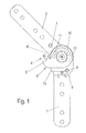
- FIGS. 1 and 2 is a locking fitting for two articulated components, in particular furniture parts shown, with a connecting plate 1 and a rotatably connected pivoting plate 2, which are locked to each other in different angular positions by means of a locking mechanism, not shown.
- a locking element 3 is provided, which is secured against rotation on the connecting lug 1, preferably, as in the example, in the region of the pivot axis 2 common with the pivoting plate.
- the locking element 3 has a recess 8, which partially surrounds a pin 9 of the terminal lug 1.
- FIG. 1 a pivoting position of the detent fitting is reproduced while the FIG. 2 shows an end position in which the terminal lug 1 and the pivot plate 2 are perpendicular to each other.
- the locking element 3 is provided with a clamp 4 which has two resilient legs 5, which form a mouth 6 open in the direction of the pivoting lug 2.
- the width of the opening of the mouth 6 is smaller than the diameter of a cylindrical detent pin 7, which on the Swivel flap 2 is attached and the pivoting of the pivoting plate 2 in the in the FIG. 2 shown end position is immersed in the mouth 6, with spreading of the legs 5, which are pressed against the locking pin 7 due to their restoring forces.
- the connecting lug 1 and the pivoting lug 2 are in an end position at right angles to each other.
- the connecting lug 1 and the pivoting plate 2 in a defined by a different angle end position is, as in the FIG. 3 very clearly visible, the locking element 4 is formed in two parts and that in the form of an upper shell 12 and a lower shell 13 which rests on the terminal lug 1, while on the upper shell 12, the clip 4 is formed.
- the lower shell 13 has, in a concentric circular arc, a row of teeth 10 into which a toothed segment 11 of the upper shell 12 engages in regions.
- This sector gear 11 is also arranged concentrically, depending on the positioning within the row of teeth 10, the angular position of the clip 4 is changed to the recess 8, whereby the locked end position of the pivot lever 2 to the connection lever 1 changes.
Abstract
Description
- Die Erfindung betrifft einen Rastbeschlag nach dem Oberbegriff des Anspruchs 1.
- Ein gattungsgemäßer Rastbeschlag, der sich insbesondere in funktionaler Hinsicht außerordentlich bewährt hat, ist aus der
DE 91 05 323 Ul bekannt. - Dabei weist das Gesperre eine Sperrklinke auf, die auf einer Schwenkachse einer Anschlusslasche gelagert ist und die in eine Außenverzahnung einer Schwenklasche eingreift und diese, je nach Schwenkwinkel, in unterschiedlichen Stellungen arretiert.
- Zur Entriegelung der Verrastung wird die Schwenklasche bzw. ein daran angeschlossenes Bauteil, vorzugsweise ein Möbelteil, wie eine Kopfstütze, Armlehne oder Fußstütze, bis in eine abgewinkelte Endstellung verschwenkt, in der die Sperrklinke außer Eingriff gelangt, so dass die Schwenklasche und mit ihr das getragene Möbelteil frei in eine mit dem anderen Möbelteil gestreckte Funktionslage zurückgeschwenkt werden kann.
- Allerdings ergibt sich in der abgewinkelten Nichtfunktionsstellung der Schwenklasche, dass durch einen die beiden Möbelteile überdeckenden Bezugsstoff eine Zugspannung auf den Rastbeschlag ausgeübt wird, die dazu führt, dass der Rastbeschlag um einen gewissen Winkelbereich zurückgeschwenkt wird, so dass eine definierte Endstellung des Rastbeschlages nicht möglich ist.
- Eine Verlängerung des Bezugsstoffes, um die genannte Spannung zu verhindern, verbietet sich allein schon deshalb, weil sich dadurch in gestreckter Lage des Rastbeschlages eine erhebliche Faltenbildung ergibt, die neben einem unschönen Aussehen zu sogenannten Schmutzecken führt, durch die der Bezugsstoff innerhalb kurzer Zeit unansehnlich wird.
- Der Erfindung liegt die Aufgabe zugrunde, einen Rastbeschlag der gattungsgemäßen Art so weiterzuentwickeln, dass seine Funktionsfähigkeit mit konstruktiv geringem Aufwand verbessert wird.
- Diese Aufgabe wird durch einen Rastbeschlag mit den Merkmalen des Anspruchs 1 gelöst.
- Durch ein entsprechend der Erfindung ausgebildetes Arretierelement wird die Schwenklasche in einer abgewinkelten Endstellung so weit sicher gehalten, dass ein Zurückschwenken auch um wenige Grade verhindert wird, wobei die Federkraft des an dem Rastzapfen anliegenden und diesen teilweise umgreifenden Schenkels so bemessen ist, dass sie einerseits größer ist als die wirksame Zugkraft bzw. Spannkraft des Bezugsstoffes, andererseits aber ein einfaches, d.h. mit sehr geringem Kraftaufwand erreichbares Zurückschwenken möglich ist.
- Nach einer vorteilhaften Weiterbildung der Erfindung weist die Klammer zwei, ein Maul bildende federnde Schenkel auf, die den Rastzapfen in Arretierstellung beidseitig teilweise umgreifen.
- Bevorzugt ist das Arretierelement als Kunststoff-Spritzgussteil ausgebildet, dessen Material dauerhaft die für die Funktionsfähigkeit der Klammer notwendigen Rückstellkräfte besitzt, wobei die Klammer so ausgebildet ist, dass ihre beiden Schenkel den Rastbolzen, der zylinderförmig ausgebildet ist, über seine Zentralachse hinaus umgreifen. Hierdurch wird ein sicherer Halt der Schwenklasche gewährleistet, andererseits aber auch ein leichtes Lösen der Arretierung.
- Als besonderer Vorteil der Erfindung ist hervorzuheben, dass das Arretierelement nachträglich an einen bereits montierten Rastbeschlag angebaut werden kann, insbesondere an einen solchen Rastbeschlag, der nicht ausgebaut werden kann, weil er beispielsweise mit einem Gestell unlösbar verbunden ist. Die Erfindung zeichnet sich dadurch aus, dass praktisch keine Veränderungen an einem bereits vorhandenen Rastbeschlag notwendig sind, außer dass der Rastbolzen an der entsprechenden Schwenklasche zu befestigen ist, was jedoch ohne nennenswerten Aufwand möglich ist. Dies gilt gleichermaßen für einen Anschlagbolzen, der mit dem Arretierelement derart korrespondiert, dass dies verdrehsicher an der Anschlusslasche gehalten ist.
- Nach einem weiteren Gedanken der Erfindung ist vorgesehen, das Arretierelement zweiteilig auszubilden und zwar mit einer Ober- und einer Unterschale.
- Die Unterschale, die an der Anschlusslasche anliegt, kann in ihrem Innenraum eine Zahnreihe aufweisen, die in einer konzentrischen Bahn angeordnet sind und bereichsweise mit einem Zahnsegment in Eingriff stehen, das in der aufliegenden Oberschale angeformt ist. Dabei ist die Anzahl der Zähne der Zahnreihe größer als die Anzahl der Zähne des Zahnsegments, so dass eine Verstellung der Oberschale gegenüber der Unterschale innerhalb eines bestimmten Winkelbereichs möglich ist, wobei die Unterschale verdrehsicher an der ersten Schwenklasche gehalten ist.
- Durch diese Verstellmöglichkeit der Ober- zur Unterschale kann die End- bzw. Arretierposition der Schwenklasche im Vorhinein festgelegt werden, je nach Wunsch und Erfordernis.
- Weitere vorteilhafte Ausbildungen der Erfindung sind in den Unteransprüchen gekennzeichnet.
- Ein Ausführungsbeispiel der Erfindung wird nachfolgend anhand der beigefügten Zeichnungen beschrieben.
- Es zeigen:
- Figuren 1 und 2
- einen erfindungsgemäßen Rastbeschlag jeweils in unterschiedlichen Stellungen in einer Seitenansicht;
- Figur 3
- eine Einzelheit des Rastbeschlages in einer schaubildlichen Darstellung.
- In den
Figuren 1 und2 ist ein Rastbeschlag für zwei gelenkig miteinander verbundene Bauteile, insbesondere Möbelteile gezeigt, mit einer Anschlusslasche 1 und einer damit drehbar verbundenen Schwenklasche 2, die in verschiedenen Winkelstellungen mittels eines nicht dargestellten Gesperres zueinander arretierbar sind. - In einer Endstellung der Schwenklasche 2, wie sie in der
Figur 2 gezeigt ist, ist das Gesperre außer Eingriff, so dass sich die Schwenklasche 2 um einen gewissen Winkelbereich frei zurückdrehen lässt. - Um dies zu verhindern, ist ein Arretierelement 3 vorgesehen, das verdrehsicher an der Anschlusslasche 1 befestigt ist, vorzugsweise, wie im Beispiel, im Bereich der mit der Schwenklasche 2 gemeinsamen Drehachse.
- Zur Verdrehsicherung weist das Arretierelement 3 eine Ausnehmung 8 auf, die bereichsweise einen Zapfen 9 der Anschlusslasche 1 umgreift.
- In der
Figur 1 ist eine Schwenkstellung des Rastbeschlages wiedergegeben, während dieFigur 2 eine Endstellung zeigt, in der die Anschlusslasche 1 und die Schwenklasche 2 rechtwinklig zueinander stehen. - Um die Schwenklasche 2 in dieser Stellung gegenüber der Anschlusslasche 1 zu halten, ist das Arretierelement 3 mit einer Klammer 4 versehen, die zwei federnde Schenkel 5 aufweist, die ein in Richtung der Schwenklasche 2 offenes Maul 6 bilden.
- Dabei ist die Breite der Öffnung des Maules 6 kleiner als der Durchmesser eines zylinderförmigen Rastzapfens 7, der an der Schwenklasche 2 befestigt ist und der bei einer Verschwenkung der Schwenklasche 2 in die in der
Figur 2 gezeigte Endstellung in das Maul 6 eintaucht, unter Aufspreizung der Schenkel 5, die aufgrund ihrer Rückstellkräfte an den Rastzapfen 7 angepresst sind. - Zum Rückschwenken der Schwenklasche 2 müssen diese Rückstellkräfte überwunden werden, die jedoch so durch Materialwahl und Dimensionierung der Klammer 4 eingestellt werden können, dass ein problemloses Lösen aus der Umklammerung durch einen Benutzer möglich ist.
- Wie erwähnt und erkennbar, stehen die Anschlusslasche 1 und die Schwenklasche 2 in einer Endstellung rechtwinklig zueinander. Um im Bedarfsfall die Anschlusslasche 1 und die Schwenklasche 2 in einer durch einen anderen Winkel definierten Endstellung zu halten, ist, wie in der
Figur 3 sehr deutlich erkennbar, das Arretierelement 4 zweiteilig ausgebildet und zwar in Form einer Oberschale 12 und einer Unterschale 13, die auf der Anschlusslasche 1 aufliegt, während an die Oberschale 12 die Klammer 4 angeformt ist. - Die Unterschale 13 weist in einem konzentrischen Kreisbogen eine Zahnreihe 10 auf, in die bereichsweise ein Zahnsegment 11 der Oberschale 12 eingreift. Dieses Zahnsegment 11 ist gleichfalls konzentrisch angeordnet, wobei je nach Positionierung innerhalb der Zahnreihe 10 die Winkelstellung der Klammer 4 zur Ausnehmung 8 verändert wird, wodurch sich auch die arretierte Endstellung des Schwenkhebels 2 zum Anschlusshebel 1 verändert.
-
- 1
- Anschlusslasche
- 2
- Schwenklasche
- 3
- Arretierelement
- 4
- Klammer
- 5
- Schenkel
- 6
- Maul
- 7
- Rastzapfen
- 8
- Ausnehmung
- 9
- Stift
- 10
- Zahnreihe
- 11
- Zahnsegment
- 12
- Oberschale
- 13
- Unterschale
Claims (8)
- Rastbeschlag für zwei gelenkig miteinander verbundene Bauteile, insbesondere Möbelteile, mit einer Anschlusslasche (1) und einer drehbar damit verbundenen Schwenklasche (2), die in verschiedenen Winkelstellungen mittels eines Gesperres zueinander arretierbar sind, wobei das Gesperre in einer Endstellung der Schwenklasche (2) außer Eingriff ist,
dadurch gekennzeichnet, dass zur Arretierung der Schwenklasche (2) in Außereingriffsstellung des Gesperres ein Arretierelement (3) verdrehsicher an der Anschlusslasche (1) befestigt ist, das eine Klammer (4) mit mindestens einem federnden Schenkel (5) aufweist, der in Arretierstellung einen an der Schwenklasche (2) befestigten Rastzapfen (7) teilweise umgreift. - Rastbeschlag nach Anspruch 1,
dadurch gekennzeichnet, dass die Klammer (4) zwei sich gegenüberliegende, ein Maul (6) bildende federnde Schenkel (5) aufweist, wobei die Öffnung des Maules (6) zum Rastzapfen (7) hin gerichtet ist. - Rastbeschlag nach Ansprach 1 oder 2,
dadurch gekennzeichnet, dass die Öffnung des Maules (6) kleiner ist als der Durchmesser des zylindrischen Rastzapfens (7). - Rastbeschlag nach einem der vorhergehenden Ansprüche,
dadurch gekennzeichnet, dass das Arretierelement (3) eine Ausnehmung (8) aufweist, in der ein an der Anschlusslasche (1) befestigter Stift (9) einhegt. - Rastbeschlag nach einem der vorhergehenden Ansprüche,
dadurch gekennzeichnet, dass das Arretierelement (3) aus einer Unterschale (13) und einer Oberschale (12) besteht, wobei die Unterschale (13) mit der Ausnehmung (8) und die Oberschale (12) mit der Klammer (4) versehen sind. - Rastbeschlag nach einem der vorhergehenden Ansprüche,
dadurch gekennzeichnet, dass die Oberschale (12) und die Unterschale (13) in unterschiedlichen Winkelstellungen zueinander arretierbar sind. - Rastbeschlag nach einem der vorhergehenden Ansprüche,
dadurch gekennzeichnet, dass die Unterschale (13) eine konzentrische, in einem Kreisbogen angeordnete Zahnreihe (10) aufweist, in die bereichsweise ein Zahnsegment (11) der Oberschale (12) eingreift. - Rastbeschlag nach einem der vorhergehenden Ansprüche,
dadurch gekennzeichnet, dass das Arretierelement (3) im Bereich einer gemeinsamen Schwenkachse der Anschlusslasche (1) und der Schwenklasche (2) angeordnet ist.
Priority Applications (1)
| Application Number | Priority Date | Filing Date | Title |
|---|---|---|---|
| PL09176664T PL2198749T3 (pl) | 2008-12-18 | 2009-11-20 | Łącznik zapadkowy |
Applications Claiming Priority (1)
| Application Number | Priority Date | Filing Date | Title |
|---|---|---|---|
| DE202008016756U DE202008016756U1 (de) | 2008-12-18 | 2008-12-18 | Rastbeschlag |
Publications (2)
| Publication Number | Publication Date |
|---|---|
| EP2198749A1 true EP2198749A1 (de) | 2010-06-23 |
| EP2198749B1 EP2198749B1 (de) | 2011-06-01 |
Family
ID=40436017
Family Applications (1)
| Application Number | Title | Priority Date | Filing Date |
|---|---|---|---|
| EP09176664A Active EP2198749B1 (de) | 2008-12-18 | 2009-11-20 | Rastbeschlag |
Country Status (4)
| Country | Link |
|---|---|
| EP (1) | EP2198749B1 (de) |
| AT (1) | ATE511366T1 (de) |
| DE (1) | DE202008016756U1 (de) |
| PL (1) | PL2198749T3 (de) |
Cited By (3)
| Publication number | Priority date | Publication date | Assignee | Title |
|---|---|---|---|---|
| EP2727496A1 (de) * | 2012-10-31 | 2014-05-07 | Motion S.r.l. | Ratschenvorrichtung |
| CN104257140A (zh) * | 2014-10-21 | 2015-01-07 | 浙江永艺家具股份有限公司 | 一种椅子脚踏的角度调节装置 |
| CN109611445A (zh) * | 2018-11-21 | 2019-04-12 | 航宇救生装备有限公司 | 一种具有快速锁定功能的装置 |
Families Citing this family (2)
| Publication number | Priority date | Publication date | Assignee | Title |
|---|---|---|---|---|
| JP4831713B1 (ja) * | 2011-04-25 | 2011-12-07 | 直伸 山下 | 角度調整金具 |
| CN105673673A (zh) * | 2016-03-04 | 2016-06-15 | 尹捷 | 无声铰链 |
Citations (8)
| Publication number | Priority date | Publication date | Assignee | Title |
|---|---|---|---|---|
| DE9105323U1 (de) | 1991-04-30 | 1991-08-01 | Ferdinand Lusch Gmbh & Co Kg, 4800 Bielefeld, De | |
| US5291634A (en) * | 1992-03-26 | 1994-03-08 | Nuova Star S.R.L. | A hinge for the constraining of hatches or doors from a support structure |
| DE4442625A1 (de) * | 1994-12-01 | 1996-06-05 | Grass Ag | Filmscharnier |
| DE20005850U1 (de) * | 2000-03-29 | 2000-07-20 | Lusch Gmbh & Co Kg Ferd | Mit mindestens einem Stützteil versehenes Sitzmöbel |
| EP1152158A1 (de) * | 1999-02-03 | 2001-11-07 | Koyo Giken Co., Ltd. | Winkelverstellvorrichtung |
| US20020069481A1 (en) * | 2000-09-21 | 2002-06-13 | Ashline Trevor P. | Door hinge check for a vehicle door |
| DE20319484U1 (de) * | 2003-12-16 | 2004-03-11 | Ferdinand Lusch Gmbh & Co. Kg | Schwenkbeschlag |
| FR2916471A1 (fr) * | 2007-05-25 | 2008-11-28 | Coutier Moulage Gen Ind | Dispositif d'arret de porte provisoire pour porte de vehicule automobile. |
-
2008
- 2008-12-18 DE DE202008016756U patent/DE202008016756U1/de not_active Expired - Lifetime
-
2009
- 2009-11-20 AT AT09176664T patent/ATE511366T1/de active
- 2009-11-20 EP EP09176664A patent/EP2198749B1/de active Active
- 2009-11-20 PL PL09176664T patent/PL2198749T3/pl unknown
Patent Citations (8)
| Publication number | Priority date | Publication date | Assignee | Title |
|---|---|---|---|---|
| DE9105323U1 (de) | 1991-04-30 | 1991-08-01 | Ferdinand Lusch Gmbh & Co Kg, 4800 Bielefeld, De | |
| US5291634A (en) * | 1992-03-26 | 1994-03-08 | Nuova Star S.R.L. | A hinge for the constraining of hatches or doors from a support structure |
| DE4442625A1 (de) * | 1994-12-01 | 1996-06-05 | Grass Ag | Filmscharnier |
| EP1152158A1 (de) * | 1999-02-03 | 2001-11-07 | Koyo Giken Co., Ltd. | Winkelverstellvorrichtung |
| DE20005850U1 (de) * | 2000-03-29 | 2000-07-20 | Lusch Gmbh & Co Kg Ferd | Mit mindestens einem Stützteil versehenes Sitzmöbel |
| US20020069481A1 (en) * | 2000-09-21 | 2002-06-13 | Ashline Trevor P. | Door hinge check for a vehicle door |
| DE20319484U1 (de) * | 2003-12-16 | 2004-03-11 | Ferdinand Lusch Gmbh & Co. Kg | Schwenkbeschlag |
| FR2916471A1 (fr) * | 2007-05-25 | 2008-11-28 | Coutier Moulage Gen Ind | Dispositif d'arret de porte provisoire pour porte de vehicule automobile. |
Cited By (4)
| Publication number | Priority date | Publication date | Assignee | Title |
|---|---|---|---|---|
| EP2727496A1 (de) * | 2012-10-31 | 2014-05-07 | Motion S.r.l. | Ratschenvorrichtung |
| CN104257140A (zh) * | 2014-10-21 | 2015-01-07 | 浙江永艺家具股份有限公司 | 一种椅子脚踏的角度调节装置 |
| CN109611445A (zh) * | 2018-11-21 | 2019-04-12 | 航宇救生装备有限公司 | 一种具有快速锁定功能的装置 |
| CN109611445B (zh) * | 2018-11-21 | 2024-01-12 | 航宇救生装备有限公司 | 一种具有快速锁定功能的装置 |
Also Published As
| Publication number | Publication date |
|---|---|
| EP2198749B1 (de) | 2011-06-01 |
| PL2198749T3 (pl) | 2011-11-30 |
| ATE511366T1 (de) | 2011-06-15 |
| DE202008016756U1 (de) | 2009-03-12 |
Similar Documents
| Publication | Publication Date | Title |
|---|---|---|
| DE102014202697B4 (de) | Sitzwinkel-Einstellmechanismus und damit ausgestatteter Kindersitz | |
| DE60129272T2 (de) | Gurtlängenanpasser | |
| DE2412500C3 (de) | Spannverschluß | |
| EP3400835B1 (de) | Schwenkbeschlag und möbel | |
| AT510436B1 (de) | Karabinerhaken | |
| DE102012015287A1 (de) | Verstellbarer Fahrzeugsitz | |
| DE102015100527A1 (de) | Schwenkbeschlag, Möbel und Kraftfahrzeugsitz | |
| EP2198749B1 (de) | Rastbeschlag | |
| EP1989960A1 (de) | Rastbeschlag | |
| DE102019101551A1 (de) | Rastklinke mit zwei nocken | |
| DE202006019497U1 (de) | Schwenkbeschlag | |
| EP1641651B1 (de) | Kindersitz | |
| DE102009009139B4 (de) | Mittelarmlehne für ein Kraftfahrzeug | |
| DE102015012411B4 (de) | Kopfstütze | |
| EP1584265B1 (de) | Rastbeschlag | |
| DE202013101759U1 (de) | Ausstattungsteil für ein Kraftfahrzeug | |
| DE202016100865U1 (de) | Stützsystem zum automatischen Zurücksetzen einer Kopfstütze | |
| DE102017009817B4 (de) | Verschließeinrichtung mit Drehelement und Blockierköpfen | |
| DE102011081686B4 (de) | Kopfstützenanordnung für einen Fahrzeugsitz | |
| DE202005003960U1 (de) | Rastbeschlag eines verstellbaren Lehnen- oder Stützteiles eines Sitz- oder Liegemöbels | |
| EP2565354A2 (de) | Schloss für die Motorhauben von Kraftfahrzeugen, insbesondere von Lastkraftwagen | |
| DE202010012472U1 (de) | Gurthöheneinstellvorrichtung sowie Fahrzeugsitz mit einer solchen | |
| DE102013102224B4 (de) | Verriegelungseinrichtung für eine Schienenführung eines Fahrzeugsitzes und Schienenführung | |
| DE7307119U (de) | Verriegelungsvorrichtung fuer einen verstellbaren kraftfahrzeugsitz | |
| DE10348067B4 (de) | Verriegelungseinrichtung für eine Schutzeinrichtung |
Legal Events
| Date | Code | Title | Description |
|---|---|---|---|
| PUAI | Public reference made under article 153(3) epc to a published international application that has entered the european phase |
Free format text: ORIGINAL CODE: 0009012 |
|
| AK | Designated contracting states |
Kind code of ref document: A1 Designated state(s): AT BE BG CH CY CZ DE DK EE ES FI FR GB GR HR HU IE IS IT LI LT LU LV MC MK MT NL NO PL PT RO SE SI SK SM TR |
|
| AX | Request for extension of the european patent |
Extension state: AL BA RS |
|
| GRAP | Despatch of communication of intention to grant a patent |
Free format text: ORIGINAL CODE: EPIDOSNIGR1 |
|
| 17P | Request for examination filed |
Effective date: 20100923 |
|
| RIC1 | Information provided on ipc code assigned before grant |
Ipc: A47C 7/38 20060101ALI20101014BHEP Ipc: A47C 7/50 20060101ALI20101014BHEP Ipc: E05D 11/10 20060101ALI20101014BHEP Ipc: A47C 1/03 20060101AFI20101014BHEP |
|
| GRAS | Grant fee paid |
Free format text: ORIGINAL CODE: EPIDOSNIGR3 |
|
| GRAA | (expected) grant |
Free format text: ORIGINAL CODE: 0009210 |
|
| AK | Designated contracting states |
Kind code of ref document: B1 Designated state(s): AT BE BG CH CY CZ DE DK EE ES FI FR GB GR HR HU IE IS IT LI LT LU LV MC MK MT NL NO PL PT RO SE SI SK SM TR |
|
| REG | Reference to a national code |
Ref country code: GB Ref legal event code: FG4D Free format text: NOT ENGLISH |
|
| REG | Reference to a national code |
Ref country code: CH Ref legal event code: EP |
|
| REG | Reference to a national code |
Ref country code: IE Ref legal event code: FG4D Free format text: LANGUAGE OF EP DOCUMENT: GERMAN |
|
| REG | Reference to a national code |
Ref country code: DE Ref legal event code: R096 Ref document number: 502009000713 Country of ref document: DE Effective date: 20110714 |
|
| REG | Reference to a national code |
Ref country code: NL Ref legal event code: VDEP Effective date: 20110601 |
|
| PG25 | Lapsed in a contracting state [announced via postgrant information from national office to epo] |
Ref country code: NO Free format text: LAPSE BECAUSE OF FAILURE TO SUBMIT A TRANSLATION OF THE DESCRIPTION OR TO PAY THE FEE WITHIN THE PRESCRIBED TIME-LIMIT Effective date: 20110901 Ref country code: HR Free format text: LAPSE BECAUSE OF FAILURE TO SUBMIT A TRANSLATION OF THE DESCRIPTION OR TO PAY THE FEE WITHIN THE PRESCRIBED TIME-LIMIT Effective date: 20110601 Ref country code: LT Free format text: LAPSE BECAUSE OF FAILURE TO SUBMIT A TRANSLATION OF THE DESCRIPTION OR TO PAY THE FEE WITHIN THE PRESCRIBED TIME-LIMIT Effective date: 20110601 Ref country code: SE Free format text: LAPSE BECAUSE OF FAILURE TO SUBMIT A TRANSLATION OF THE DESCRIPTION OR TO PAY THE FEE WITHIN THE PRESCRIBED TIME-LIMIT Effective date: 20110601 |
|
| PG25 | Lapsed in a contracting state [announced via postgrant information from national office to epo] |
Ref country code: SI Free format text: LAPSE BECAUSE OF FAILURE TO SUBMIT A TRANSLATION OF THE DESCRIPTION OR TO PAY THE FEE WITHIN THE PRESCRIBED TIME-LIMIT Effective date: 20110601 Ref country code: ES Free format text: LAPSE BECAUSE OF FAILURE TO SUBMIT A TRANSLATION OF THE DESCRIPTION OR TO PAY THE FEE WITHIN THE PRESCRIBED TIME-LIMIT Effective date: 20110912 Ref country code: FI Free format text: LAPSE BECAUSE OF FAILURE TO SUBMIT A TRANSLATION OF THE DESCRIPTION OR TO PAY THE FEE WITHIN THE PRESCRIBED TIME-LIMIT Effective date: 20110601 Ref country code: LV Free format text: LAPSE BECAUSE OF FAILURE TO SUBMIT A TRANSLATION OF THE DESCRIPTION OR TO PAY THE FEE WITHIN THE PRESCRIBED TIME-LIMIT Effective date: 20110601 Ref country code: CY Free format text: LAPSE BECAUSE OF FAILURE TO SUBMIT A TRANSLATION OF THE DESCRIPTION OR TO PAY THE FEE WITHIN THE PRESCRIBED TIME-LIMIT Effective date: 20110601 |
|
| REG | Reference to a national code |
Ref country code: PL Ref legal event code: T3 |
|
| REG | Reference to a national code |
Ref country code: IE Ref legal event code: FD4D |
|
| PG25 | Lapsed in a contracting state [announced via postgrant information from national office to epo] |
Ref country code: NL Free format text: LAPSE BECAUSE OF FAILURE TO SUBMIT A TRANSLATION OF THE DESCRIPTION OR TO PAY THE FEE WITHIN THE PRESCRIBED TIME-LIMIT Effective date: 20110601 |
|
| PG25 | Lapsed in a contracting state [announced via postgrant information from national office to epo] |
Ref country code: IE Free format text: LAPSE BECAUSE OF FAILURE TO SUBMIT A TRANSLATION OF THE DESCRIPTION OR TO PAY THE FEE WITHIN THE PRESCRIBED TIME-LIMIT Effective date: 20110601 Ref country code: EE Free format text: LAPSE BECAUSE OF FAILURE TO SUBMIT A TRANSLATION OF THE DESCRIPTION OR TO PAY THE FEE WITHIN THE PRESCRIBED TIME-LIMIT Effective date: 20110601 Ref country code: CZ Free format text: LAPSE BECAUSE OF FAILURE TO SUBMIT A TRANSLATION OF THE DESCRIPTION OR TO PAY THE FEE WITHIN THE PRESCRIBED TIME-LIMIT Effective date: 20110601 Ref country code: PT Free format text: LAPSE BECAUSE OF FAILURE TO SUBMIT A TRANSLATION OF THE DESCRIPTION OR TO PAY THE FEE WITHIN THE PRESCRIBED TIME-LIMIT Effective date: 20111003 Ref country code: IS Free format text: LAPSE BECAUSE OF FAILURE TO SUBMIT A TRANSLATION OF THE DESCRIPTION OR TO PAY THE FEE WITHIN THE PRESCRIBED TIME-LIMIT Effective date: 20111001 |
|
| PG25 | Lapsed in a contracting state [announced via postgrant information from national office to epo] |
Ref country code: SK Free format text: LAPSE BECAUSE OF FAILURE TO SUBMIT A TRANSLATION OF THE DESCRIPTION OR TO PAY THE FEE WITHIN THE PRESCRIBED TIME-LIMIT Effective date: 20110601 |
|
| PLBE | No opposition filed within time limit |
Free format text: ORIGINAL CODE: 0009261 |
|
| STAA | Information on the status of an ep patent application or granted ep patent |
Free format text: STATUS: NO OPPOSITION FILED WITHIN TIME LIMIT |
|
| 26N | No opposition filed |
Effective date: 20120302 |
|
| BERE | Be: lapsed |
Owner name: FERDINAND LUSCH G.M.B.H. & CO. KG. Effective date: 20111130 |
|
| REG | Reference to a national code |
Ref country code: DE Ref legal event code: R097 Ref document number: 502009000713 Country of ref document: DE Effective date: 20120302 |
|
| PG25 | Lapsed in a contracting state [announced via postgrant information from national office to epo] |
Ref country code: DK Free format text: LAPSE BECAUSE OF FAILURE TO SUBMIT A TRANSLATION OF THE DESCRIPTION OR TO PAY THE FEE WITHIN THE PRESCRIBED TIME-LIMIT Effective date: 20110601 Ref country code: MC Free format text: LAPSE BECAUSE OF NON-PAYMENT OF DUE FEES Effective date: 20111130 |
|
| REG | Reference to a national code |
Ref country code: FR Ref legal event code: ST Effective date: 20120731 |
|
| PG25 | Lapsed in a contracting state [announced via postgrant information from national office to epo] |
Ref country code: BE Free format text: LAPSE BECAUSE OF NON-PAYMENT OF DUE FEES Effective date: 20111130 |
|
| PG25 | Lapsed in a contracting state [announced via postgrant information from national office to epo] |
Ref country code: FR Free format text: LAPSE BECAUSE OF NON-PAYMENT OF DUE FEES Effective date: 20111130 |
|
| PG25 | Lapsed in a contracting state [announced via postgrant information from national office to epo] |
Ref country code: MK Free format text: LAPSE BECAUSE OF FAILURE TO SUBMIT A TRANSLATION OF THE DESCRIPTION OR TO PAY THE FEE WITHIN THE PRESCRIBED TIME-LIMIT Effective date: 20110601 Ref country code: MT Free format text: LAPSE BECAUSE OF FAILURE TO SUBMIT A TRANSLATION OF THE DESCRIPTION OR TO PAY THE FEE WITHIN THE PRESCRIBED TIME-LIMIT Effective date: 20110601 |
|
| PG25 | Lapsed in a contracting state [announced via postgrant information from national office to epo] |
Ref country code: SM Free format text: LAPSE BECAUSE OF FAILURE TO SUBMIT A TRANSLATION OF THE DESCRIPTION OR TO PAY THE FEE WITHIN THE PRESCRIBED TIME-LIMIT Effective date: 20110601 |
|
| PG25 | Lapsed in a contracting state [announced via postgrant information from national office to epo] |
Ref country code: LU Free format text: LAPSE BECAUSE OF NON-PAYMENT OF DUE FEES Effective date: 20111120 |
|
| PG25 | Lapsed in a contracting state [announced via postgrant information from national office to epo] |
Ref country code: BG Free format text: LAPSE BECAUSE OF FAILURE TO SUBMIT A TRANSLATION OF THE DESCRIPTION OR TO PAY THE FEE WITHIN THE PRESCRIBED TIME-LIMIT Effective date: 20110901 |
|
| PG25 | Lapsed in a contracting state [announced via postgrant information from national office to epo] |
Ref country code: TR Free format text: LAPSE BECAUSE OF FAILURE TO SUBMIT A TRANSLATION OF THE DESCRIPTION OR TO PAY THE FEE WITHIN THE PRESCRIBED TIME-LIMIT Effective date: 20110601 |
|
| PG25 | Lapsed in a contracting state [announced via postgrant information from national office to epo] |
Ref country code: HU Free format text: LAPSE BECAUSE OF FAILURE TO SUBMIT A TRANSLATION OF THE DESCRIPTION OR TO PAY THE FEE WITHIN THE PRESCRIBED TIME-LIMIT Effective date: 20110601 |
|
| PGFP | Annual fee paid to national office [announced via postgrant information from national office to epo] |
Ref country code: DE Payment date: 20131120 Year of fee payment: 5 |
|
| PGFP | Annual fee paid to national office [announced via postgrant information from national office to epo] |
Ref country code: IT Payment date: 20131127 Year of fee payment: 5 Ref country code: PL Payment date: 20131011 Year of fee payment: 5 |
|
| REG | Reference to a national code |
Ref country code: CH Ref legal event code: PL |
|
| GBPC | Gb: european patent ceased through non-payment of renewal fee |
Effective date: 20131120 |
|
| PG25 | Lapsed in a contracting state [announced via postgrant information from national office to epo] |
Ref country code: LI Free format text: LAPSE BECAUSE OF NON-PAYMENT OF DUE FEES Effective date: 20131130 Ref country code: CH Free format text: LAPSE BECAUSE OF NON-PAYMENT OF DUE FEES Effective date: 20131130 |
|
| PG25 | Lapsed in a contracting state [announced via postgrant information from national office to epo] |
Ref country code: GR Free format text: LAPSE BECAUSE OF FAILURE TO SUBMIT A TRANSLATION OF THE DESCRIPTION OR TO PAY THE FEE WITHIN THE PRESCRIBED TIME-LIMIT Effective date: 20110601 |
|
| PG25 | Lapsed in a contracting state [announced via postgrant information from national office to epo] |
Ref country code: GB Free format text: LAPSE BECAUSE OF NON-PAYMENT OF DUE FEES Effective date: 20131120 |
|
| REG | Reference to a national code |
Ref country code: DE Ref legal event code: R119 Ref document number: 502009000713 Country of ref document: DE |
|
| PG25 | Lapsed in a contracting state [announced via postgrant information from national office to epo] |
Ref country code: DE Free format text: LAPSE BECAUSE OF NON-PAYMENT OF DUE FEES Effective date: 20150602 |
|
| PG25 | Lapsed in a contracting state [announced via postgrant information from national office to epo] |
Ref country code: IT Free format text: LAPSE BECAUSE OF NON-PAYMENT OF DUE FEES Effective date: 20141120 |
|
| REG | Reference to a national code |
Ref country code: AT Ref legal event code: MM01 Ref document number: 511366 Country of ref document: AT Kind code of ref document: T Effective date: 20141120 |
|
| PG25 | Lapsed in a contracting state [announced via postgrant information from national office to epo] |
Ref country code: PL Free format text: LAPSE BECAUSE OF NON-PAYMENT OF DUE FEES Effective date: 20141120 Ref country code: AT Free format text: LAPSE BECAUSE OF NON-PAYMENT OF DUE FEES Effective date: 20141120 |