EP2196726A1 - Fahrzeugausleuchtungslampe - Google Patents
Fahrzeugausleuchtungslampe Download PDFInfo
- Publication number
- EP2196726A1 EP2196726A1 EP09014617A EP09014617A EP2196726A1 EP 2196726 A1 EP2196726 A1 EP 2196726A1 EP 09014617 A EP09014617 A EP 09014617A EP 09014617 A EP09014617 A EP 09014617A EP 2196726 A1 EP2196726 A1 EP 2196726A1
- Authority
- EP
- European Patent Office
- Prior art keywords
- light
- distribution pattern
- light distribution
- mirror member
- reflective surface
- Prior art date
- Legal status (The legal status is an assumption and is not a legal conclusion. Google has not performed a legal analysis and makes no representation as to the accuracy of the status listed.)
- Granted
Links
Images


Classifications
-
- F—MECHANICAL ENGINEERING; LIGHTING; HEATING; WEAPONS; BLASTING
- F21—LIGHTING
- F21V—FUNCTIONAL FEATURES OR DETAILS OF LIGHTING DEVICES OR SYSTEMS THEREOF; STRUCTURAL COMBINATIONS OF LIGHTING DEVICES WITH OTHER ARTICLES, NOT OTHERWISE PROVIDED FOR
- F21V29/00—Protecting lighting devices from thermal damage; Cooling or heating arrangements specially adapted for lighting devices or systems
- F21V29/50—Cooling arrangements
- F21V29/70—Cooling arrangements characterised by passive heat-dissipating elements, e.g. heat-sinks
- F21V29/74—Cooling arrangements characterised by passive heat-dissipating elements, e.g. heat-sinks with fins or blades
- F21V29/76—Cooling arrangements characterised by passive heat-dissipating elements, e.g. heat-sinks with fins or blades with essentially identical parallel planar fins or blades, e.g. with comb-like cross-section
-
- F—MECHANICAL ENGINEERING; LIGHTING; HEATING; WEAPONS; BLASTING
- F21—LIGHTING
- F21S—NON-PORTABLE LIGHTING DEVICES; SYSTEMS THEREOF; VEHICLE LIGHTING DEVICES SPECIALLY ADAPTED FOR VEHICLE EXTERIORS
- F21S41/00—Illuminating devices specially adapted for vehicle exteriors, e.g. headlamps
- F21S41/10—Illuminating devices specially adapted for vehicle exteriors, e.g. headlamps characterised by the light source
- F21S41/14—Illuminating devices specially adapted for vehicle exteriors, e.g. headlamps characterised by the light source characterised by the type of light source
- F21S41/141—Light emitting diodes [LED]
- F21S41/147—Light emitting diodes [LED] the main emission direction of the LED being angled to the optical axis of the illuminating device
- F21S41/148—Light emitting diodes [LED] the main emission direction of the LED being angled to the optical axis of the illuminating device the main emission direction of the LED being perpendicular to the optical axis
-
- F—MECHANICAL ENGINEERING; LIGHTING; HEATING; WEAPONS; BLASTING
- F21—LIGHTING
- F21S—NON-PORTABLE LIGHTING DEVICES; SYSTEMS THEREOF; VEHICLE LIGHTING DEVICES SPECIALLY ADAPTED FOR VEHICLE EXTERIORS
- F21S41/00—Illuminating devices specially adapted for vehicle exteriors, e.g. headlamps
- F21S41/10—Illuminating devices specially adapted for vehicle exteriors, e.g. headlamps characterised by the light source
- F21S41/14—Illuminating devices specially adapted for vehicle exteriors, e.g. headlamps characterised by the light source characterised by the type of light source
- F21S41/141—Light emitting diodes [LED]
- F21S41/151—Light emitting diodes [LED] arranged in one or more lines
-
- B—PERFORMING OPERATIONS; TRANSPORTING
- B60—VEHICLES IN GENERAL
- B60Q—ARRANGEMENT OF SIGNALLING OR LIGHTING DEVICES, THE MOUNTING OR SUPPORTING THEREOF OR CIRCUITS THEREFOR, FOR VEHICLES IN GENERAL
- B60Q2300/00—Indexing codes for automatically adjustable headlamps or automatically dimmable headlamps
- B60Q2300/05—Special features for controlling or switching of the light beam
- B60Q2300/056—Special anti-blinding beams, e.g. a standard beam is chopped or moved in order not to blind
-
- F—MECHANICAL ENGINEERING; LIGHTING; HEATING; WEAPONS; BLASTING
- F21—LIGHTING
- F21S—NON-PORTABLE LIGHTING DEVICES; SYSTEMS THEREOF; VEHICLE LIGHTING DEVICES SPECIALLY ADAPTED FOR VEHICLE EXTERIORS
- F21S45/00—Arrangements within vehicle lighting devices specially adapted for vehicle exteriors, for purposes other than emission or distribution of light
- F21S45/40—Cooling of lighting devices
- F21S45/47—Passive cooling, e.g. using fins, thermal conductive elements or openings
-
- F—MECHANICAL ENGINEERING; LIGHTING; HEATING; WEAPONS; BLASTING
- F21—LIGHTING
- F21Y—INDEXING SCHEME ASSOCIATED WITH SUBCLASSES F21K, F21L, F21S and F21V, RELATING TO THE FORM OR THE KIND OF THE LIGHT SOURCES OR OF THE COLOUR OF THE LIGHT EMITTED
- F21Y2115/00—Light-generating elements of semiconductor light sources
- F21Y2115/10—Light-emitting diodes [LED]
Definitions
- the present invention relates to a vehicular illumination lamp configured so as to form an additional light distribution pattern for high beam, and particularly relates to a vehicular illumination lamp with light-emitting elements serving as a light source.
- a light-emitting element such as a light-emitting diode has been increasingly employed as a light source for a vehicular illumination lamp that composes a headlamp.
- Patent Document 1 describes a vehicular illumination lamp that forms an additional light distribution pattern for high beam (that is, a light distribution pattern formed in addition to a low-beam distribution pattern when a high-beam distribution pattern is formed) by using a lamp unit with a plurality of light-emitting elements serving as a light source.
- the plurality of light-emitting elements are configured to be arranged horizontally side by side with each other in the vicinity of a rear focal plane of a projection lens, and by synthesizing light distribution patterns formed as inverted projection images of these light-emitting elements, the additional light distribution pattern for high beam is formed.
- Patent Document 2 describes a lamp unit that includes a projection lens arranged on an optical axis extending in the vehicular longitudinal direction, a pair of light-emitting elements arranged facing upward and downward, respectively, in the vicinity of the optical axis on the rear side of a rear side focal point of the projection lens, a pair of reflectors that are arranged so as to cover the pair of light-emitting elements from above and below, respectively, and that reflect light from the light-emitting elements in the direction closer to the optical axis toward the front, and a double-sided mirror piece that is arranged so as to extend generally along a horizontal plane including the optical axis between the pair of reflectors and the projection lens and that is formed so that the front end edge thereof passes through the rear side focal point of the projection lens.
- the double-sided mirror piece is configured so as to reflect part of reflected light from the upper side reflector upward and part of reflected light from the lower side reflector downward.
- a plurality of light distribution patterns are formed in a horizontally parallel manner with the radiated light. Therefore, if each of the light-emitting elements is controlled to turn on and off so that the plurality of light distribution patterns do not include a light distribution pattern to be formed at a position of an oncoming vehicle or a leading vehicle, it is made possible to improve visibility of an area ahead of a vehicle without giving glare to the driver of the oncoming vehicle or the leading vehicle.
- a vehicular illumination lamp that is configured so as to form an additional light distribution pattern for high beam, and is capable of improving visibility of an area ahead of a vehicle without giving glare to a driver of an oncoming vehicle or a leading vehicle.
- the present invention intends to achieve the object by providing a configuration in which a pair of lamp units are respectively swiveled in the horizontal direction by a pair of swivel mechanisms, and in addition, by providing a configuration in which a light distribution pattern having a clear outline of the left side end edge thereof is formed with light radiated from one of the lamp units and a light distribution pattern having a clear outline of the right side end edge thereof is formed with light radiated from the other of the lamp units.
- a vehicular illumination lamp is configured so as to form an additional light distribution pattern in addition to a low-beam distribution pattern when a high-beam distribution pattern is formed, and is characterized by including a first lamp unit that includes a projection lens arranged on an optical axis extending in the vehicular longitudinal direction, a light-emitting element arranged facing toward the left side in the vicinity of the optical axis on the rear side of a rear side focal point of the projection lens, a reflector that is arranged so as to cover the light-emitting element from the left side, and that reflects light from the light-emitting element in the direction closer to the optical axis toward the front, and a mirror member that is arranged between the reflector and the projection lens and that reflects part of reflected light from the reflector toward the left side, the mirror member being formed so that a reflective surface of the mirror member extends generally along a vertical plane including the optical axis and a front end edge of the reflective surface passes through the rear side focal point
- the "light-emitting element” above denotes a light source in the form of an element having a light emitting-chip that performs surface light emission generally in the shape of a point.
- the type of the light-emitting element is not particularly limited.
- a light-emitting diode or a laser diode may be employed.
- each of the lamp units is not particularly limited as far as the mirror member is formed so that the reflective surface thereof extends generally along the vertical plane including the optical axis and the front end edge of the reflective surface passes through the rear side focal point of the projection lens.
- each of the mirror members may be formed as the same flat surface as the vertical plane including the optical axis, or may be formed as a flat surface or a curved surface somewhat inclined from the aforementioned flat surface.
- each of the mirror members may obviously be formed so as to extend in the vertical direction, and may also be formed so as to extend in the direction somewhat inclined from the vertical direction.
- the positional relationship between the "first lamp unit” and the “second lamp unit” is not particularly limited, and, for example, a configuration in which the lamp units are arranged laterally adjacent to each other or a configuration in which the lamp units are arranged vertically adjacent to each other may be employed.
- the vehicular illumination lamp according to the present invention is provided with the pair of projector-type lamp units in which the light-emitting elements and the reflectors are arranged in the rear of the projection lenses.
- the first lamp unit is configured such that the mirror member that is arranged between the reflector and the projection lens reflects part of reflected light from the reflector toward the left side
- the second lamp unit is configured such that the mirror member that is arranged between the reflector and the projection lens reflects part of reflected light from the reflector toward the right side.
- the reflective surface of the mirror member in each of these lamp units is formed so as to extend generally along the vertical plane including the optical axis and so that the front end edge of the reflective surface passes through the rear side focal point of the projection lens. Therefore, the following effects can be obtained.
- a first light distribution pattern formed with the reflected light from the reflector of the first lamp unit is formed with a vertical cut-off line, which extends in the generally vertical direction with respect to the forward direction of the lamp, at the left end edge of the first light distribution pattern as an inverted projection image of the front end edge of the reflective surface of the mirror member.
- a second light distribution pattern formed with the reflected light from the reflector of the second lamp unit is formed with a vertical cut-off line extends in the generally vertical direction with respect to the forward direction of the lamp, at the right end edge of the second light distribution pattern as an inverted projection image of the front end edge of the reflective surface of the mirror member.
- the left end portion of the first light distribution pattern is formed by synthesizing light that is directly incident on the projection lens after being reflected from the reflector of the first lamp unit and light that is incident on the projection lens after being reflected from this reflector and then reflected by the mirror member, distinction of the vertical cut-off line can be sufficiently ensured.
- the right end portion of the second light distribution pattern is formed by synthesizing light that is directly incident on the projection lens after being reflected from the reflector of the second lamp unit and light that is incident on the projection lens after being reflected from this reflector and then reflected by the mirror member, distinction of the vertical cut-off line can be sufficiently ensured.
- the first light distribution pattern having the distinct vertical cut-off line at the left end edge is formed in a manner extending toward the right side from the directly forward direction of the lamp.
- the second light distribution pattern having the distinct vertical cut-off line at the right end edge is formed in a manner extending toward the left side from the directly forward direction of the lamp.
- a third light distribution pattern that is provided by synthesizing the first and the second light distribution patterns is formed in a manner diffusing toward both the right and left sides from the directly forward direction of the lamp, in a state in which both of the vertical cut-off lines generally coincide with each other.
- any one of the first, the second, and the third light distribution patterns can be selectively displaced in the lateral direction as an additional light distribution pattern for high beam.
- the vertical cut-off line of the first light distribution pattern can be formed near the right side of an oncoming vehicle or a leading vehicle.
- the vertical cut-off line of the second light distribution pattern can be formed near the left side of the oncoming vehicle or the leading vehicle.
- a diffusion light distribution pattern can be formed in an appropriate direction depending on the degree of curvature of the vehicle running path, and so on, by displacing the third light distribution pattern in the lateral direction.
- the vehicular illumination lamp configured so as to form the additional light distribution pattern for high beam, visibility of the area ahead of the vehicle can be improved without giving glare to the driver of the oncoming vehicle or the leading vehicle.
- the front end edge of the reflective surface in each of the mirror members is configured to include a lower vertical portion extending generally directly downward from the rear side focal point of each of the projection lens, a horizontal portion extending generally directly rearward from an upper end position of the lower vertical portion, and an upper vertical portion extending generally directly upward from a rear end position of the horizontal portion, and if it is configured such that the mirror member of the first lamp unit is formed with an upward reflective surface extending generally horizontally toward the right side from the horizontal portion on the front end edge of the reflective surface of the mirror member while the mirror member of the second lamp unit is formed with an upward reflective surface extending generally horizontally toward the left side from the horizontal portion on the front end edge of the reflective surface of the mirror member, the following effects can be obtained.
- the upper vertical portion of the front end edge of the reflective surface in each of the mirror members is offset to the rear side of the lower vertical portion of the front end edge. Therefore, on the basis that an upper half portion of the left end edge of the first light distribution pattern is formed as the vertical cut-off line, a lower half portion of the left end edge can be formed in a position offset to the left side of the position of the vertical cut-off line. On the other hand, on the basis that an upper half portion of the right end edge of the second light distribution pattern is formed as the vertical cut-off line, a lower half portion of the right end edge can be formed in a position offset to the right side of the position of the vertical cut-off line.
- the additional light distribution pattern for high beam can be formed in a state in which an extended portion that extends to the left side of the vertical cut-off line in the first light distribution pattern and an extended portion that extends to the right side of the vertical cut-off line in the second light distribution pattern partially overlap each other.
- the mirror member of the first lamp unit is formed with the upward reflective surface extending generally horizontally toward the right side from the horizontal portion on the front end edge of the reflective surface of the mirror member, a horizontal cut-off line extending toward the left side from a lower end position of the vertical cut-off line is formed at an upper end edge of the extended portion of the first light distribution pattern, as an inverted projection image of the front end edge of the upward reflective surface.
- the mirror member of the second lamp unit is formed with the upward reflective surface extending generally horizontally toward the left side from the horizontal portion on the front end edge of the reflective surface of the mirror member, a horizontal cut-off line extending toward the right side from a lower end position of the vertical cut-off line is formed at an upper end edge of the extended portion of the second light distribution pattern, as an inverted projection image of the front end edge of the upward reflective surface.
- FIG. 1 is a front view showing a vehicular illumination lamp 10 constructed according to a preferred embodiment of the present invention.
- the vehicular illumination lamp 10 has a configuration in which a lamp chamber formed with a lamp body 12 and with a plain translucent cover 14 mounted at a front end opening of the lamp body 12 houses a pair of right and left lamp units 20A, 20B and a pair of swivel mechanisms 50A, 50B that independently swivel the lamp units 20A, 20B, respectively, in the horizontal direction.
- the lamp unit 20A (first lamp unit) has a configuration laterally symmetrical to that of the lamp unit 20B (second lamp unit), and the swivel mechanism 50A (first swivel mechanism) has the same configuration as that of the swivel mechanism 50B (second swivel mechanism).
- each optical axis Ax of each of the lamp units 20A, 20B extends to the forward direction of a vehicle.
- This additional light distribution pattern PA is a light distribution pattern that is formed in addition to a low-beam distribution pattern PL formed with light radiated from another vehicular illumination lamp (not shown), and as a synthesized light distribution pattern of the aforementioned patterns, a high-beam distribution pattern PH is formed.
- the additional light distribution pattern PA is also formed in forms other than the form shown in FIG. 4A . However, description will be made later in this respect.
- FIG. 2 is a II-II line cross-sectional view of FIG. 1
- FIG. 3 is a III-III line cross-sectional view of FIG. 1 .
- the lamp unit 20A is provided with a projection lens 22 arranged on the optical axis Ax, a light-emitting element 24A arranged facing toward the left side in the vicinity of the optical axis Ax on the rear side of a rear side focal point F of the projection lens 22, a reflector 26A that is arranged so as to cover the light-emitting element 24A from the left side and that reflects light from the light-emitting element 24A in the direction closer to the optical axis Ax toward the front, and a mirror member 28A that is arranged between the reflector 26A and the projection lens 22.
- the projection lens 22 is composed of a planoconvex aspheric lens having a forward side surface as a convex surface and a rearward side surface as a flat surface, and projects a light source image formed on a rear focal plane of the lens on a virtual vertical screen in front of the lamp as an inverted image.
- the projection lens 22 is fixedly supported by a lens holder 30 of a ring shape.
- the lens holder 30 is formed with a pair of brackets 30a extending rearward from rear surfaces of both upper and lower ends of the lens holder 30.
- the light-emitting element 24A is a white light-emitting diode, and composed of a light-emitting chip 24a constituting a horizontally oblong shaped light-emitting surface, a substrate 24b supporting the light-emitting chip 24a, and a metallic supporting plate 24c supporting the substrate 24b.
- the light-emitting chip 24a is formed by horizontally arranging four light-emitting chips, each of which has a square light-emitting surface of approximately 1 mm on a side, so as to be generally in close contact with each other.
- the light-emitting chip 24a is sealed with a thin film that is formed so as to cover the light-emitting surface of the chip.
- a reflective surface 26Aa of the reflector 26A is formed of a curved surface of a generally ellipsoidal shape having a long axis extending generally in parallel with the optical axis Ax and also having a first focal point at the center of light emission of the light-emitting element 24A, and is set to gradually decrease in eccentricity from the horizontal cross-sectional plane toward the vertical cross-sectional plane.
- the reflector 26A makes the light from the light-emitting element 24A substantially converge slightly in front of the rear side focal point F in the vertical cross-sectional plane, and moves the converging point forward by a large amount in the horizontal cross-sectional plane.
- the mirror member 28A is a plate member made of metal that is arranged so that a left side surface thereof extends along a vertical plane including the optical axis Ax.
- the left side surface of the mirror member 28A is treated with mirror processing so as to form a reflective surface 28Aa that reflects part of reflected light from the reflector 26A toward the left side.
- a front end edge 28Aa1 of the reflective surface 28Aa of the mirror member 28A extends in the vertical direction so as to pass through the rear side focal point F.
- a heat sink 28Ab is formed on the right side surface of the mirror member 28A.
- the heat sink 28Ab is provided with a plurality of radiation fins extending along a vertical plane orthogonal to the optical axis Ax.
- the light-emitting element 24A is fixedly supported at the supporting plate 24c thereof in a depressed portion 28Ac that is formed so as to be a lower step in the rear of the left side surface of the mirror member 28A.
- the reflector 26A is fixedly supported by the left side surface of the mirror member 28A.
- the mirror member 28A is fixedly supported at both upper and lower ends thereof by the pair of upper and lower brackets 30a of the lens holder 30.
- the swivel mechanism 50A is composed of a frame member 52 that supports the lamp unit 20A on the pair of upper and lower brackets 30a of the lens holder 30 so as to be rotatable around an axis line Ax1 extending in the vertical direction, and an actuator 54 that is fixed to the frame member 52 on the lower side of the frame member 52 and that rotates the lamp unit 20A around the axis line Ax1.
- the frame member 52 of the swivel mechanism 50A is also used as the frame member 52 of the other swivel mechanism 50B.
- the other lamp unit 20B is also supported by the frame member 52 on the pair of upper and lower brackets 30a of the lens holder 30 so as to be rotatable around an axis line Ax1 extending in the vertical direction.
- the frame member 52 is supported so as to be tiltable relative to the lamp body 12. Consequently, the light axis adjustment of both the lamp units 20A, 20B can be performed in one adjustment operation.
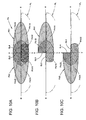
- FIG. 4A is a perspective view showing the additional light distribution pattern PA formed, with the light radiated forward from the vehicular illumination lamp 10 according to the present embodiment, on the virtual vertical screen arranged at a position 25 m ahead of the vehicle, together with the low-beam distribution pattern PL formed with the light radiated from another vehicular illumination lamp.
- the high-beam distribution pattern PH is formed by adding the additional light distribution pattern PA to the low-beam distribution pattern PL.
- the low-beam distribution pattern PL Before describing the additional light distribution pattern PA, the low-beam distribution pattern PL will be described.
- the low-beam distribution pattern PL is a low-beam distribution pattern for left side light distribution, and has horizontal cut-off lines CL1, CL2 at the upper end edge thereof in a stepped fashion to the right and the left.
- the horizontal cut-off lines CL1, CL2 extend horizontally in a stepped fashion to the right and the left of a line V-V that is a vertical line passing through a vanishing point H-V in the forward direction of the lamp.
- the cut-off line is formed as the horizontal cut-off line CL1 on the opposing-lane side that extends horizontally
- the cut-off line is formed as the horizontal cut-off line CL2 on the self-lane side that extends horizontally in a fashion stepped upward from the horizontal cut-off line CL1.
- the end portion of the horizontal cut-off line CL2 on the side near to the line V-V is formed as an oblique cut-off line that extends diagonally upward left at an inclination angle of 15° from an intersection point between the horizontal cut-off line CL1 and the line V-V.
- an elbow point E that is the intersection point between the horizontal cut-off line CL1 and the line V-V is located downward by approximately 0.5° to 0.6° from the point H-V, and a hot zone HZ serving as an area of high-intensity light is formed so as to surround the elbow point E slightly close to the left.
- the additional light distribution pattern PA is formed as a synthesized light distribution pattern of an additional light distribution pattern PA1 that is formed with light radiated from the lamp unit 20A and an additional light distribution pattern PA2 that is formed with light radiated from the lamp unit 20B.
- the additional light distribution pattern PA shown in A of the same drawing is a light distribution pattern that is formed when both the lamp units 20A, 20B are under the standard condition (that is, the condition in which the swivel driving is not performed by each of the swivel mechanisms 50A, 50B) and also when the light-emitting elements 24A, 24B of both the lamp units 20A, 20B are lit at the same time.
- FIG. 6 shows views illustrating the additional light distribution patterns formed on the virtual vertical screen with the light radiated from both the lamp units 20A, 20B.
- the additional light distribution pattern PA shown in A of the same drawing is a light distribution pattern that is formed when the light-emitting elements 24A, 24B of the lamp units 20A, 20B that are both under the standard condition are lit at the same time.
- the additional light distribution pattern PA1 shown in B of the same drawing is a light distribution pattern that is formed when only the light-emitting element 24A of the lamp unit 20A is lit
- the additional light distribution pattern PA2 shown in C of the same drawing is a light distribution pattern that is formed when only the light-emitting element 24B of the lamp unit 20B is lit.
- the additional light distribution pattern PA is formed in a manner vertically crossing over the horizontal cut-off lines CL1, CL2 of the low-beam distribution pattern PL. In that situation, the additional light distribution pattern PA is formed as a horizontally long light distribution pattern extending in both the right and the left directions from the point H-V serving as a center.
- the additional light distribution pattern PA1 is formed as a horizontally long light distribution pattern spreading toward the right side from the line V-V. In that situation, the additional light distribution pattern PA1 is formed as a vertically symmetrical light distribution pattern with respect to a line H-H that is a horizontal line passing through the point H-V.
- the additional light distribution pattern PA1 is formed as a synthesized light distribution pattern of a light distribution pattern PA1A and a light distribution pattern PA1B, and formed at the left end edge thereof with a distinct vertical cut-off line CL3 extending in the vertical direction along the line V-V.
- the light distribution pattern PA1A of the additional light distribution pattern PA1 is a light distribution pattern formed with light from the light-emitting element 24A that is directly incident on the projection lens 22 of the lamp unit 20A after being reflected by the reflector 26A of the lamp unit 20A.
- the light distribution pattern PA1B is a light distribution pattern formed with light from the light-emitting element 24A that is incident on the projection lens 22 of the lamp unit 20A after being reflected by the reflector 26A of the lamp unit 20A and then by the reflective surface 28Aa of the mirror member 28A.
- the light distribution pattern PA1B is formed so as to overlap with the light distribution pattern PA1A in the left end portion of the light distribution pattern PA1A.
- the vertical cut-off line CL3 in the additional light distribution pattern PA1 is formed as an inverted projection image of the front end edge 28Aa1 of the reflective surface 28Aa of the mirror member 28A. In that situation, the vertical cut-off line CL3 is formed to be highly distinct because the vertical cut-off line CL3 is formed in the same position by each of the light distribution patterns PA1A, PA1B.
- the additional light distribution pattern PA2 is formed to be a light distribution pattern laterally symmetrical to the additional light distribution pattern PA1 with respect to the line V-V.
- the additional light distribution pattern PA2 is formed as a horizontally long light distribution pattern spreading toward the right side from the line V-V.
- the additional light distribution pattern PA2 is formed as a synthesized light distribution pattern of a light distribution pattern PA2A that is formed with light that is reflected from a reflector 26B of the lamp unit 20B and directly incident on the projection lens 22, and a light distribution pattern PA2B that is formed with light that is reflected from the reflector 26B and then directly incident on the projection lens 22 after being reflected by a reflective surface 28Ba of a mirror member 28B.
- the right end edge of the additional light distribution pattern PA2 is formed with a distinct vertical cut-off line CL4 extending in the vertical direction along the line V-V as an inverted projection image of a front end edge 28Ba1 of the reflective surface 28Ba of the mirror member 28B.
- the additional light distribution pattern PA synthesized from the additional light distribution patterns PA1, PA2 is formed in a manner spreading toward both the right and left sides from the directly forward direction of the lamp, in a state in which both of the vertical cut-off lines CL3, CL4 coincide with each other on the line V-V.
- the position of the vertical cut-off line CL3 and the position of the vertical cut-off line CL4 exactly coincide with each other on the line V-V, because both the front end edge 28Aa1 of the reflective surface 28Aa on the mirror member 28A of the lamp unit 20A and the front end edge 28Ba1 of the reflective surface 28Ba on the mirror member 28B of the lamp unit 20B extend in the vertical direction so as to pass through the rear side focal point F.
- the vehicular illumination lamp 10 is provided with the pair of projector-type lamp units 20A, 20B.
- the lamp unit 20A is configured such that the mirror member 28A thereof that is arranged between the reflector 26A and the projection lens 22 reflects part of reflected light from the reflector 26A toward the left side
- the lamp unit 20B is configured such that the mirror member 28B thereof that is arranged between the reflector 26B and the projection lens 22 reflects part of reflected light from the reflector 26B toward the right side.
- the reflective surfaces 28Aa, 28Ba of the mirror members 28A, 28B in the lamp units 20A, 20B are formed so as to extend along the vertical planes including the optical axes Ax and formed so that the front end edges 28Aa1, 28Ba1 of the reflective surfaces 28Aa, 28Ba pass through the rear side focal points F of the projection lenses 22. Therefore, the following effects can be obtained.
- the additional light distribution pattern PA1 (first light distribution pattern) formed with the reflected light from the reflector 26A of the lamp unit 20A is formed with the vertical cut-off line CL3, which extends in the generally vertical direction with respect to the forward direction of the lamp, at the left end edge of the additional light distribution pattern PA1 as the inverted projection image of the front end edge 28Aa1 of the reflective surface 28Aa of the mirror member 28A.
- the additional light distribution pattern PA2 (second light distribution pattern) formed with the reflected light from the reflector 26B of the lamp unit 20B is formed with the vertical cut-off line CL4, which extends in the generally vertical direction with respect to the forward direction of the lamp, at the right end edge of the additional light distribution pattern PA2 as the inverted projection image of the front end edge 28Ba1 of the reflective surface 28Ba of the mirror member 28B.
- the left end portion of the additional light distribution pattern PA1 is formed by synthesizing the light that is directly incident on the projection lens 22 after being reflected from the reflector 26A of the lamp unit 20A and the light that is incident on the projection lens 22 after being reflected from the reflector 26A and then reflected by the mirror member 28A, distinction of the vertical cut-off line CL3 can be sufficiently ensured.
- the right end portion of the additional light distribution pattern PA2 is formed by synthesizing the light that is directly incident on the projection lens 22 after being reflected from the reflector 26B of the lamp unit 20B and the light that is incident on the projection lens 22 after being reflected from the reflector 26B and then reflected by the mirror member 28B, distinction of the vertical cut-off line CL4 can be sufficiently ensured.
- the additional light distribution pattern PA1 having the distinct vertical cut-off line CL3 at the left end edge is formed in a manner extending toward the right side from the directly forward direction of the lamp.
- the additional light distribution pattern PA2 having the distinct vertical cut-off line CL4 at the right end edge is formed in a manner extending toward the left side from the directly forward direction of the lamp.
- the additional light distribution pattern PA (third light distribution pattern) that is provided by synthesizing the two additional light distribution patterns PA1, PA2 is formed in a manner diffusing toward both the right and left sides from the directly forward direction of the lamp in the state in which both of the vertical cut-off lines CL3, CL4 coincide with each other.
- any one of the additional light distribution patterns PA1, PA2, and PA can be selectively displaced in the lateral direction.
- the vertical cut-off line CL3 of the additional light distribution pattern PA1 can be formed near the right side of an oncoming vehicle or a leading vehicle.
- the vertical cut-off line CL4 of the additional light distribution pattern PA2 can be formed near the left side of the oncoming vehicle or the leading vehicle.
- a diffusion light distribution pattern can be formed in an appropriate direction depending on the degree of curvature of the vehicle running path, and so on, by displacing the additional light distribution pattern PA in the lateral direction.
- the vehicular illumination lamp 10 configured so as to form the additional light distribution pattern for high beam, visibility of the area ahead of the vehicle can be improved without giving glare to the driver of the oncoming vehicle or the leading vehicle.
- the vehicular illumination lamp 10 is provided with the two sets of the lamp units 20A, 20B and the swivel mechanisms 50A, 50B, it is made possible by appropriately combining the directions of both the lamp units 20A, 20B to radiate light to areas on both the right and left sides of the vehicle without giving glare to the driver of the oncoming vehicle or the leading vehicle. Consequently, visibility of the area ahead of the vehicle can be further improved.
- the additional light distribution pattern PA1 is formed in a position displaced to the right from the position shown in FIG. 4A by swiveling the one lamp unit 20A from the standard condition to the right to a predetermined angle by using the swivel mechanism 50A.
- the additional light distribution pattern PA2 is formed in a position displaced to the left from the position shown in FIG. 4A by swiveling the other lamp unit 20B from the standard condition to the left to the predetermined angle by using the swivel mechanism 50B.
- the pair of additional light distribution patterns PA1, PA2 can be formed in a state in which the vertical cut-off lines CL3, CL4 thereof are located close to both the right and left sides, respectively, of the leading vehicle 2. Then, as a result, it is possible to radiate light to areas on both the right and left sides of the leading vehicle 2 without giving glare to the driver of the leading vehicle.
- the additional light distribution pattern PA1 is formed in a position displaced by a relatively large amount to the right from the position shown in FIG. 4A by swiveling the one lamp unit 20A by a relatively large angle from the standard condition to the right by using the swivel mechanism 50A.
- the additional light distribution pattern PA2 is formed in a position displaced by a relatively small amount to the right from the position shown in FIG. 4A by swiveling the other lamp unit 20B by a relatively small angle from the standard condition to the right by using the swivel mechanism 50B.
- the pair of additional light distribution patterns PA1, PA2 can be formed in a state in which the vertical cut-off lines CL3, CL4 thereof are located close to both the right and left sides, respectively, of the oncoming vehicle 4. Then, as a result, it is made possible to radiate light to areas on both the right and left sides of the oncoming vehicle 4 without giving glare to the driver of the oncoming vehicle.
- the pair of additional light distribution patterns PA1, PA2 can be formed in a state in which the vertical cut-off lines CL3, CL4 thereof are located close to both the right and left sides, respectively, of the oncoming vehicle 4, by increasing the rightward swivel angles of both the lamp units 20A, 20B by angles different from each other depending on the position of the oncoming vehicle 4.
- the position of the leading vehicle 2 or the oncoming vehicle 4 on the virtual vertical screen can be detected in a simple manner, for example, by taking an image of a scene ahead of the vehicle using a CCD camera or the like, and by detecting the positions of tail lamps of the leading vehicle 2 in a lit state or the positions of headlamps of the oncoming vehicle 4 in a lit state as high concentration pixels, based on the captured image data.
- FIG. 7 is a view similar to FIG. 2 , showing a lamp unit 120A of a vehicular illumination lamp according to the modification example.
- the configuration of a mirror member 128A of the lamp unit 120A is different from that of the mirror member 28A of the above embodiment.
- a front end edge of a reflective surface 128Aa of the mirror member 128A is composed of a lower vertical portion 128Aa1 extending directly downward from the rear side focal point F of the projection lens 22, a horizontal portion 128Aa2 extending directly rearward from an upper end position of the lower vertical portion 128Aa1, and an upper vertical portion 128Aa3 extending directly upward from a rear end position of the horizontal portion 128Aa2.
- FIG. 8 is a perspective view showing an essential part of the mirror member 128A.
- the mirror member 128A is formed with an upward reflective surface 128Ad that extends horizontally toward the right side from the horizontal portion 128Aa2 on the front end edge of the reflective surface 128Aa of the mirror member 128A.
- the upward reflective surface 128Ad is formed with a width equal to the thickness of the mirror member 128A.
- the vehicular illumination lamp according to the modification example is also provided with a lamp unit (not shown) that has a configuration laterally symmetrical to that of the lamp unit 120A.
- FIG. 9 and FIG. 10 show, similarly to FIG. 4 and FIG. 6 , respectively, views illustrating operations of the modification example.
- an upper half portion of the left end edge is formed as the vertical cut-off line CL3, and a lower half portion thereof is formed in a position offset to the left side of the position of the vertical cut-off line CL3.
- an upper end edge of the extended portion PA1C in the additional light distribution pattern PA1 is formed as a horizontal cut-off line CL5 that extends toward the left side from a lower end position of the vertical cut-off line CL3.
- This cut-off line is formed as an inverted projection image of a front end edge 128Ad1 of the upward reflective surface 128Ad that is formed so as to extend horizontally toward the right side from the horizontal portion 128Aa2 on the front end edge of the reflective surface 128Aa on the mirror member 128A of the lamp unit 120A.
- the light distribution pattern PA1A formed with light from the light-emitting element 24A that is directly incident on the projection lens 22 of the lamp unit 120A after being reflected by the reflector 26A of the lamp unit 120A is the same as that of the above embodiment
- the light distribution pattern PA1B formed with light from the light-emitting element 24A that is incident on the projection lens 22 of the lamp unit 120A after being reflected by the reflector 26A of the lamp unit 120A and then by the reflective surface 128Aa of the mirror member 128A has a slightly darker lower half portion in brightness. This is because the amount of light reflected by the reflective surface 128Aa is reduced corresponding to the rearward offset of the upper vertical portion 128Aa3 on the front end edge of the reflective surface 128Aa.
- the additional light distribution pattern PA2 that is formed with light radiated from the other lamp unit (not shown) is formed to be a light distribution pattern laterally symmetrical to the additional light distribution pattern PA1 with respect to the line V-V.
- an upper half portion of the right end edge of the additional light distribution pattern PA2 is formed as the vertical cut-off line CL4, and a lower half portion thereof is formed as a somewhat indistinct outline in a position offset to the right side of the position of the vertical cut-off line CL4.
- an extended portion PA2C that extends to the right side of the vertical cut-off line CL4 in the additional light distribution pattern PA2 has a somewhat indistinct outline at the right end edge thereof, and an upper end edge of the extended portion PA2C is formed as a horizontal cut-off line CL6 that extends toward the right side from a lower end position of the vertical cut-off line CL4.
- the additional light distribution pattern PA synthesized from the additional light distribution patterns PA1, PA2 is formed in a manner spreading toward both the right and left sides from the directly forward direction of the lamp, in a state in which both of the vertical cut-off lines CL3, CL4 coincide with each other on the line V-V in the upper half portion and the extended portions PA1C, PA2C overlap each other in the lower half portion.
- the additional light distribution pattern PA that is generally the same as that of the embodiment can be formed under the standard condition.
- the pair of additional light distribution patterns PA1, PA2 can be formed in a state in which the vertical cut-off lines CL3, CL4 thereof are located close to both the right and left sides, respectively, of the leading vehicle 2. Then, as a result, it is made possible to radiate light to areas on both the right and left sides of the leading vehicle 2 without giving glare to the driver of the leading vehicle.
- both of the additional light distribution patterns PA1, PA2 are formed in the state in which the vertical cut-off lines CL3, CL4 thereof are separated from each other, if the distance between the vertical cut-off lines CL3, CL4 is relatively small, the extended portion PA1C that extends to the left side of the vertical cut-off line CL3 in the additional light distribution pattern PA1 and the extended portion PA2C that extends to the right side of the vertical cut-off line CL4 in the additional light distribution pattern PA2 can partially overlap each other.
- each of the light-emitting elements 24A, 24B has the light-emitting chip 24a provided with the horizontally arranged four light-emitting chips, each of which has the square light-emitting surface of approximately 1 mm on a side, so as to be generally in close contact with each other.
- the light-emitting elements 24A, 24B so as to have light-emitting chips having other shapes or sizes. By using such a configuration, it is possible to adjust shapes or brightness of the additional light distribution patterns PA, PA1, PA2 in an appropriate manner.
Applications Claiming Priority (1)
| Application Number | Priority Date | Filing Date | Title |
|---|---|---|---|
| JP2008313278A JP5133862B2 (ja) | 2008-12-09 | 2008-12-09 | 車両用照明灯具 |
Publications (2)
| Publication Number | Publication Date |
|---|---|
| EP2196726A1 true EP2196726A1 (de) | 2010-06-16 |
| EP2196726B1 EP2196726B1 (de) | 2014-12-24 |
Family
ID=42026333
Family Applications (1)
| Application Number | Title | Priority Date | Filing Date |
|---|---|---|---|
| EP09014617.6A Not-in-force EP2196726B1 (de) | 2008-12-09 | 2009-11-24 | Fahrzeugausleuchtungslampe |
Country Status (3)
| Country | Link |
|---|---|
| EP (1) | EP2196726B1 (de) |
| JP (1) | JP5133862B2 (de) |
| CN (1) | CN101806422B (de) |
Cited By (8)
| Publication number | Priority date | Publication date | Assignee | Title |
|---|---|---|---|---|
| EP2284439A3 (de) * | 2009-08-13 | 2011-05-11 | Automotive Lighting Reutlingen GmbH | Frontscheinwerfer mit einem LED-Teilfernlichtmodul |
| WO2012038172A1 (de) * | 2010-09-21 | 2012-03-29 | Osram Ag | Leuchtvorrichtung |
| EP2436968A1 (de) | 2010-09-29 | 2012-04-04 | Valeo Vision | Vorrichtung zur Ausstrahlung von Licht für einen Autoscheinwerfer |
| EP2565530A1 (de) | 2011-09-05 | 2013-03-06 | Valeo Vision | Optisches Modul für Vorrichtung zur Signalisierung und/oder Beleuchtung |
| EP2610549A3 (de) * | 2011-12-30 | 2014-07-30 | Automotive Lighting Reutlingen GmbH | Scheinwerfer für ein Kraftfahrzeug, der eine Teilfernlicht-Lichtverteilung mit Hilfe eines Reflexionssystems erzeugt |
| EP3034933A1 (de) * | 2012-05-22 | 2016-06-22 | Koito Manufacturing Co., Ltd. | Fahrzeugscheinwerfer |
| CN106247244A (zh) * | 2015-06-03 | 2016-12-21 | 株式会社小糸制作所 | 车辆用灯具 |
| EP3222910A1 (de) * | 2010-07-26 | 2017-09-27 | Valeo Vision | Optisches modul einer beleuchtung- und/oder signalisierungvorrichtung eines kraftfahrzeugs |
Families Citing this family (9)
| Publication number | Priority date | Publication date | Assignee | Title |
|---|---|---|---|---|
| CN102313154A (zh) * | 2010-07-01 | 2012-01-11 | 光联科技股份有限公司 | 照明系统和薄板光屏蔽照明装置 |
| JP5719620B2 (ja) * | 2011-02-04 | 2015-05-20 | 株式会社小糸製作所 | 車両用前照灯の配光制御装置 |
| JP5666977B2 (ja) * | 2011-04-26 | 2015-02-12 | 株式会社小糸製作所 | 車両用灯具 |
| JP5758724B2 (ja) * | 2011-07-07 | 2015-08-05 | 株式会社小糸製作所 | 車輌用前照灯 |
| JP2013161567A (ja) * | 2012-02-02 | 2013-08-19 | Ichikoh Ind Ltd | 車両用前照灯および車両用前照灯装置 |
| KR101360344B1 (ko) * | 2012-02-17 | 2014-02-10 | 현대모비스 주식회사 | 차량용 램프 제어장치 및 제어방법 |
| JP6211817B2 (ja) * | 2013-06-10 | 2017-10-11 | 株式会社小糸製作所 | 車両用灯具 |
| KR20190015486A (ko) * | 2016-06-03 | 2019-02-13 | 루미리즈 홀딩 비.브이. | 반사기 내에 2개의 필라멘트를 갖고 이러한 램프를 장착한 차량 헤드라이트 |
| JP7269025B2 (ja) * | 2019-02-12 | 2023-05-08 | 株式会社小糸製作所 | 車両用灯具 |
Citations (5)
| Publication number | Priority date | Publication date | Assignee | Title |
|---|---|---|---|---|
| JP2005108554A (ja) | 2003-09-29 | 2005-04-21 | Koito Mfg Co Ltd | 車両用前照灯 |
| US20070147055A1 (en) * | 2005-12-28 | 2007-06-28 | Koito Manufacturing Co., Ltd. | Vehicle lighting device |
| EP1935715A1 (de) * | 2006-12-19 | 2008-06-25 | Ichikoh Industries, Ltd. | Fahrzeugbeleuchtungsvorrichtung |
| US20080198617A1 (en) * | 2007-02-21 | 2008-08-21 | Gm Global Technology Operations, Inc. | LED Adaptive Forward Lighting Systems |
| US20080225535A1 (en) * | 2007-03-15 | 2008-09-18 | Koito Manufacturing Co., Ltd. | Headlamp having selectable beam |
Family Cites Families (5)
| Publication number | Priority date | Publication date | Assignee | Title |
|---|---|---|---|---|
| CN2565670Y (zh) * | 2002-09-10 | 2003-08-13 | 徐洪瑞 | 机动车前照灯电子控制转向装置 |
| JP4094446B2 (ja) * | 2003-02-03 | 2008-06-04 | 株式会社小糸製作所 | 車両用前照灯及び発光モジュール |
| JP2007115541A (ja) * | 2005-10-20 | 2007-05-10 | Yamaha Corp | 光源ユニット |
| JP4597890B2 (ja) * | 2006-03-29 | 2010-12-15 | 株式会社小糸製作所 | 車両用前照灯の灯具ユニット |
| JP4607811B2 (ja) * | 2006-04-18 | 2011-01-05 | 株式会社小糸製作所 | 車両用照明灯具 |
-
2008
- 2008-12-09 JP JP2008313278A patent/JP5133862B2/ja not_active Expired - Fee Related
-
2009
- 2009-11-24 EP EP09014617.6A patent/EP2196726B1/de not_active Not-in-force
- 2009-12-09 CN CN2009110002089A patent/CN101806422B/zh not_active Expired - Fee Related
Patent Citations (6)
| Publication number | Priority date | Publication date | Assignee | Title |
|---|---|---|---|---|
| JP2005108554A (ja) | 2003-09-29 | 2005-04-21 | Koito Mfg Co Ltd | 車両用前照灯 |
| US20070147055A1 (en) * | 2005-12-28 | 2007-06-28 | Koito Manufacturing Co., Ltd. | Vehicle lighting device |
| JP2007179969A (ja) | 2005-12-28 | 2007-07-12 | Koito Mfg Co Ltd | 車両用灯具 |
| EP1935715A1 (de) * | 2006-12-19 | 2008-06-25 | Ichikoh Industries, Ltd. | Fahrzeugbeleuchtungsvorrichtung |
| US20080198617A1 (en) * | 2007-02-21 | 2008-08-21 | Gm Global Technology Operations, Inc. | LED Adaptive Forward Lighting Systems |
| US20080225535A1 (en) * | 2007-03-15 | 2008-09-18 | Koito Manufacturing Co., Ltd. | Headlamp having selectable beam |
Cited By (10)
| Publication number | Priority date | Publication date | Assignee | Title |
|---|---|---|---|---|
| EP2284439A3 (de) * | 2009-08-13 | 2011-05-11 | Automotive Lighting Reutlingen GmbH | Frontscheinwerfer mit einem LED-Teilfernlichtmodul |
| EP3222910A1 (de) * | 2010-07-26 | 2017-09-27 | Valeo Vision | Optisches modul einer beleuchtung- und/oder signalisierungvorrichtung eines kraftfahrzeugs |
| WO2012038172A1 (de) * | 2010-09-21 | 2012-03-29 | Osram Ag | Leuchtvorrichtung |
| EP2436968A1 (de) | 2010-09-29 | 2012-04-04 | Valeo Vision | Vorrichtung zur Ausstrahlung von Licht für einen Autoscheinwerfer |
| EP2565530A1 (de) | 2011-09-05 | 2013-03-06 | Valeo Vision | Optisches Modul für Vorrichtung zur Signalisierung und/oder Beleuchtung |
| FR2979688A1 (fr) * | 2011-09-05 | 2013-03-08 | Valeo Vision | Module optique pour dispositif de signalisation et/ou d'eclairage |
| EP2610549A3 (de) * | 2011-12-30 | 2014-07-30 | Automotive Lighting Reutlingen GmbH | Scheinwerfer für ein Kraftfahrzeug, der eine Teilfernlicht-Lichtverteilung mit Hilfe eines Reflexionssystems erzeugt |
| EP3034933A1 (de) * | 2012-05-22 | 2016-06-22 | Koito Manufacturing Co., Ltd. | Fahrzeugscheinwerfer |
| CN106247244A (zh) * | 2015-06-03 | 2016-12-21 | 株式会社小糸制作所 | 车辆用灯具 |
| CN106247244B (zh) * | 2015-06-03 | 2019-03-15 | 株式会社小糸制作所 | 车辆用灯具 |
Also Published As
| Publication number | Publication date |
|---|---|
| CN101806422B (zh) | 2011-12-14 |
| EP2196726B1 (de) | 2014-12-24 |
| JP2010140662A (ja) | 2010-06-24 |
| JP5133862B2 (ja) | 2013-01-30 |
| CN101806422A (zh) | 2010-08-18 |
Similar Documents
| Publication | Publication Date | Title |
|---|---|---|
| EP2196726B1 (de) | Fahrzeugausleuchtungslampe | |
| EP2196727B1 (de) | Fahrzeugausleuchtungslampe | |
| US7824086B2 (en) | Lamp unit for vehicle headlamp and vehicle headlamp | |
| EP2407710B1 (de) | Fahrzeugleuchte | |
| EP1970617B1 (de) | Lampeneinheit | |
| US9765938B2 (en) | Vehicle headlamp | |
| EP2103867B1 (de) | Fahrzeugscheinwerfervorrichtung | |
| JP4663548B2 (ja) | 車両用前照灯の灯具ユニット | |
| JP5323449B2 (ja) | 車両用灯具ユニット及び車両用灯具 | |
| EP2487407B1 (de) | Fahrzeugbeleuchtungsvorrichtung | |
| JP4781951B2 (ja) | 車両用灯具ユニット及び車両用灯具 | |
| JP5281359B2 (ja) | 車両用灯具ユニット及び車両用灯具 | |
| US8651717B2 (en) | Vehicular illumination lamp | |
| JP2009184410A (ja) | 車両用照明灯具 | |
| JP2010140663A (ja) | 車両用照明灯具 | |
| CN111550745B (zh) | 车辆用灯具 | |
| EP2172694B1 (de) | Fahrzeuglampe | |
| EP2228593B1 (de) | Fahrzeugscheinwerfer | |
| US20090316415A1 (en) | Lamp unit | |
| JP2022144102A (ja) | 車両用灯具 | |
| JP2023044895A (ja) | 車両用灯具 |
Legal Events
| Date | Code | Title | Description |
|---|---|---|---|
| PUAI | Public reference made under article 153(3) epc to a published international application that has entered the european phase |
Free format text: ORIGINAL CODE: 0009012 |
|
| 17P | Request for examination filed |
Effective date: 20100105 |
|
| AK | Designated contracting states |
Kind code of ref document: A1 Designated state(s): AT BE BG CH CY CZ DE DK EE ES FI FR GB GR HR HU IE IS IT LI LT LU LV MC MK MT NL NO PL PT RO SE SI SK SM TR |
|
| AX | Request for extension of the european patent |
Extension state: AL BA RS |
|
| GRAP | Despatch of communication of intention to grant a patent |
Free format text: ORIGINAL CODE: EPIDOSNIGR1 |
|
| INTG | Intention to grant announced |
Effective date: 20140805 |
|
| GRAS | Grant fee paid |
Free format text: ORIGINAL CODE: EPIDOSNIGR3 |
|
| GRAA | (expected) grant |
Free format text: ORIGINAL CODE: 0009210 |
|
| AK | Designated contracting states |
Kind code of ref document: B1 Designated state(s): AT BE BG CH CY CZ DE DK EE ES FI FR GB GR HR HU IE IS IT LI LT LU LV MC MK MT NL NO PL PT RO SE SI SK SM TR |
|
| REG | Reference to a national code |
Ref country code: GB Ref legal event code: FG4D |
|
| REG | Reference to a national code |
Ref country code: CH Ref legal event code: EP |
|
| REG | Reference to a national code |
Ref country code: IE Ref legal event code: FG4D |
|
| REG | Reference to a national code |
Ref country code: AT Ref legal event code: REF Ref document number: 703351 Country of ref document: AT Kind code of ref document: T Effective date: 20150115 |
|
| REG | Reference to a national code |
Ref country code: DE Ref legal event code: R096 Ref document number: 602009028503 Country of ref document: DE Effective date: 20150219 |
|
| REG | Reference to a national code |
Ref country code: NL Ref legal event code: VDEP Effective date: 20141224 |
|
| PG25 | Lapsed in a contracting state [announced via postgrant information from national office to epo] |
Ref country code: FI Free format text: LAPSE BECAUSE OF FAILURE TO SUBMIT A TRANSLATION OF THE DESCRIPTION OR TO PAY THE FEE WITHIN THE PRESCRIBED TIME-LIMIT Effective date: 20141224 Ref country code: LT Free format text: LAPSE BECAUSE OF FAILURE TO SUBMIT A TRANSLATION OF THE DESCRIPTION OR TO PAY THE FEE WITHIN THE PRESCRIBED TIME-LIMIT Effective date: 20141224 Ref country code: NO Free format text: LAPSE BECAUSE OF FAILURE TO SUBMIT A TRANSLATION OF THE DESCRIPTION OR TO PAY THE FEE WITHIN THE PRESCRIBED TIME-LIMIT Effective date: 20150324 |
|
| REG | Reference to a national code |
Ref country code: LT Ref legal event code: MG4D |
|
| PG25 | Lapsed in a contracting state [announced via postgrant information from national office to epo] |
Ref country code: HR Free format text: LAPSE BECAUSE OF FAILURE TO SUBMIT A TRANSLATION OF THE DESCRIPTION OR TO PAY THE FEE WITHIN THE PRESCRIBED TIME-LIMIT Effective date: 20141224 Ref country code: GR Free format text: LAPSE BECAUSE OF FAILURE TO SUBMIT A TRANSLATION OF THE DESCRIPTION OR TO PAY THE FEE WITHIN THE PRESCRIBED TIME-LIMIT Effective date: 20150325 Ref country code: LV Free format text: LAPSE BECAUSE OF FAILURE TO SUBMIT A TRANSLATION OF THE DESCRIPTION OR TO PAY THE FEE WITHIN THE PRESCRIBED TIME-LIMIT Effective date: 20141224 Ref country code: SE Free format text: LAPSE BECAUSE OF FAILURE TO SUBMIT A TRANSLATION OF THE DESCRIPTION OR TO PAY THE FEE WITHIN THE PRESCRIBED TIME-LIMIT Effective date: 20141224 |
|
| REG | Reference to a national code |
Ref country code: AT Ref legal event code: MK05 Ref document number: 703351 Country of ref document: AT Kind code of ref document: T Effective date: 20141224 |
|
| PG25 | Lapsed in a contracting state [announced via postgrant information from national office to epo] |
Ref country code: NL Free format text: LAPSE BECAUSE OF FAILURE TO SUBMIT A TRANSLATION OF THE DESCRIPTION OR TO PAY THE FEE WITHIN THE PRESCRIBED TIME-LIMIT Effective date: 20141224 |
|
| PG25 | Lapsed in a contracting state [announced via postgrant information from national office to epo] |
Ref country code: CZ Free format text: LAPSE BECAUSE OF FAILURE TO SUBMIT A TRANSLATION OF THE DESCRIPTION OR TO PAY THE FEE WITHIN THE PRESCRIBED TIME-LIMIT Effective date: 20141224 Ref country code: RO Free format text: LAPSE BECAUSE OF FAILURE TO SUBMIT A TRANSLATION OF THE DESCRIPTION OR TO PAY THE FEE WITHIN THE PRESCRIBED TIME-LIMIT Effective date: 20141224 Ref country code: SK Free format text: LAPSE BECAUSE OF FAILURE TO SUBMIT A TRANSLATION OF THE DESCRIPTION OR TO PAY THE FEE WITHIN THE PRESCRIBED TIME-LIMIT Effective date: 20141224 Ref country code: EE Free format text: LAPSE BECAUSE OF FAILURE TO SUBMIT A TRANSLATION OF THE DESCRIPTION OR TO PAY THE FEE WITHIN THE PRESCRIBED TIME-LIMIT Effective date: 20141224 Ref country code: ES Free format text: LAPSE BECAUSE OF FAILURE TO SUBMIT A TRANSLATION OF THE DESCRIPTION OR TO PAY THE FEE WITHIN THE PRESCRIBED TIME-LIMIT Effective date: 20141224 |
|
| PG25 | Lapsed in a contracting state [announced via postgrant information from national office to epo] |
Ref country code: AT Free format text: LAPSE BECAUSE OF FAILURE TO SUBMIT A TRANSLATION OF THE DESCRIPTION OR TO PAY THE FEE WITHIN THE PRESCRIBED TIME-LIMIT Effective date: 20141224 Ref country code: IS Free format text: LAPSE BECAUSE OF FAILURE TO SUBMIT A TRANSLATION OF THE DESCRIPTION OR TO PAY THE FEE WITHIN THE PRESCRIBED TIME-LIMIT Effective date: 20150424 Ref country code: PL Free format text: LAPSE BECAUSE OF FAILURE TO SUBMIT A TRANSLATION OF THE DESCRIPTION OR TO PAY THE FEE WITHIN THE PRESCRIBED TIME-LIMIT Effective date: 20141224 |
|
| REG | Reference to a national code |
Ref country code: DE Ref legal event code: R097 Ref document number: 602009028503 Country of ref document: DE |
|
| REG | Reference to a national code |
Ref country code: FR Ref legal event code: PLFP Year of fee payment: 7 |
|
| PG25 | Lapsed in a contracting state [announced via postgrant information from national office to epo] |
Ref country code: DK Free format text: LAPSE BECAUSE OF FAILURE TO SUBMIT A TRANSLATION OF THE DESCRIPTION OR TO PAY THE FEE WITHIN THE PRESCRIBED TIME-LIMIT Effective date: 20141224 |
|
| PLBE | No opposition filed within time limit |
Free format text: ORIGINAL CODE: 0009261 |
|
| STAA | Information on the status of an ep patent application or granted ep patent |
Free format text: STATUS: NO OPPOSITION FILED WITHIN TIME LIMIT |
|
| 26N | No opposition filed |
Effective date: 20150925 |
|
| PG25 | Lapsed in a contracting state [announced via postgrant information from national office to epo] |
Ref country code: IT Free format text: LAPSE BECAUSE OF FAILURE TO SUBMIT A TRANSLATION OF THE DESCRIPTION OR TO PAY THE FEE WITHIN THE PRESCRIBED TIME-LIMIT Effective date: 20141224 |
|
| PG25 | Lapsed in a contracting state [announced via postgrant information from national office to epo] |
Ref country code: SI Free format text: LAPSE BECAUSE OF FAILURE TO SUBMIT A TRANSLATION OF THE DESCRIPTION OR TO PAY THE FEE WITHIN THE PRESCRIBED TIME-LIMIT Effective date: 20141224 |
|
| PG25 | Lapsed in a contracting state [announced via postgrant information from national office to epo] |
Ref country code: BE Free format text: LAPSE BECAUSE OF FAILURE TO SUBMIT A TRANSLATION OF THE DESCRIPTION OR TO PAY THE FEE WITHIN THE PRESCRIBED TIME-LIMIT Effective date: 20141224 |
|
| PG25 | Lapsed in a contracting state [announced via postgrant information from national office to epo] |
Ref country code: MC Free format text: LAPSE BECAUSE OF FAILURE TO SUBMIT A TRANSLATION OF THE DESCRIPTION OR TO PAY THE FEE WITHIN THE PRESCRIBED TIME-LIMIT Effective date: 20141224 Ref country code: LU Free format text: LAPSE BECAUSE OF FAILURE TO SUBMIT A TRANSLATION OF THE DESCRIPTION OR TO PAY THE FEE WITHIN THE PRESCRIBED TIME-LIMIT Effective date: 20151124 |
|
| REG | Reference to a national code |
Ref country code: CH Ref legal event code: PL |
|
| GBPC | Gb: european patent ceased through non-payment of renewal fee |
Effective date: 20151124 |
|
| PG25 | Lapsed in a contracting state [announced via postgrant information from national office to epo] |
Ref country code: CH Free format text: LAPSE BECAUSE OF NON-PAYMENT OF DUE FEES Effective date: 20151130 Ref country code: LI Free format text: LAPSE BECAUSE OF NON-PAYMENT OF DUE FEES Effective date: 20151130 |
|
| REG | Reference to a national code |
Ref country code: IE Ref legal event code: MM4A |
|
| REG | Reference to a national code |
Ref country code: FR Ref legal event code: PLFP Year of fee payment: 8 |
|
| PG25 | Lapsed in a contracting state [announced via postgrant information from national office to epo] |
Ref country code: IE Free format text: LAPSE BECAUSE OF NON-PAYMENT OF DUE FEES Effective date: 20151124 Ref country code: GB Free format text: LAPSE BECAUSE OF NON-PAYMENT OF DUE FEES Effective date: 20151124 |
|
| PG25 | Lapsed in a contracting state [announced via postgrant information from national office to epo] |
Ref country code: SM Free format text: LAPSE BECAUSE OF FAILURE TO SUBMIT A TRANSLATION OF THE DESCRIPTION OR TO PAY THE FEE WITHIN THE PRESCRIBED TIME-LIMIT Effective date: 20141224 Ref country code: BG Free format text: LAPSE BECAUSE OF FAILURE TO SUBMIT A TRANSLATION OF THE DESCRIPTION OR TO PAY THE FEE WITHIN THE PRESCRIBED TIME-LIMIT Effective date: 20141224 Ref country code: HU Free format text: LAPSE BECAUSE OF FAILURE TO SUBMIT A TRANSLATION OF THE DESCRIPTION OR TO PAY THE FEE WITHIN THE PRESCRIBED TIME-LIMIT; INVALID AB INITIO Effective date: 20091124 |
|
| PG25 | Lapsed in a contracting state [announced via postgrant information from national office to epo] |
Ref country code: CY Free format text: LAPSE BECAUSE OF FAILURE TO SUBMIT A TRANSLATION OF THE DESCRIPTION OR TO PAY THE FEE WITHIN THE PRESCRIBED TIME-LIMIT Effective date: 20141224 |
|
| PG25 | Lapsed in a contracting state [announced via postgrant information from national office to epo] |
Ref country code: TR Free format text: LAPSE BECAUSE OF FAILURE TO SUBMIT A TRANSLATION OF THE DESCRIPTION OR TO PAY THE FEE WITHIN THE PRESCRIBED TIME-LIMIT Effective date: 20141224 Ref country code: MT Free format text: LAPSE BECAUSE OF FAILURE TO SUBMIT A TRANSLATION OF THE DESCRIPTION OR TO PAY THE FEE WITHIN THE PRESCRIBED TIME-LIMIT Effective date: 20141224 |
|
| REG | Reference to a national code |
Ref country code: FR Ref legal event code: PLFP Year of fee payment: 9 |
|
| REG | Reference to a national code |
Ref country code: DE Ref legal event code: R079 Ref document number: 602009028503 Country of ref document: DE Free format text: PREVIOUS MAIN CLASS: F21S0008120000 Ipc: F21S0041000000 |
|
| PG25 | Lapsed in a contracting state [announced via postgrant information from national office to epo] |
Ref country code: MK Free format text: LAPSE BECAUSE OF FAILURE TO SUBMIT A TRANSLATION OF THE DESCRIPTION OR TO PAY THE FEE WITHIN THE PRESCRIBED TIME-LIMIT Effective date: 20141224 |
|
| PG25 | Lapsed in a contracting state [announced via postgrant information from national office to epo] |
Ref country code: PT Free format text: LAPSE BECAUSE OF FAILURE TO SUBMIT A TRANSLATION OF THE DESCRIPTION OR TO PAY THE FEE WITHIN THE PRESCRIBED TIME-LIMIT Effective date: 20141224 |
|
| REG | Reference to a national code |
Ref country code: FR Ref legal event code: PLFP Year of fee payment: 10 |
|
| PGFP | Annual fee paid to national office [announced via postgrant information from national office to epo] |
Ref country code: DE Payment date: 20181113 Year of fee payment: 10 |
|
| PGFP | Annual fee paid to national office [announced via postgrant information from national office to epo] |
Ref country code: FR Payment date: 20181011 Year of fee payment: 10 |
|
| REG | Reference to a national code |
Ref country code: DE Ref legal event code: R119 Ref document number: 602009028503 Country of ref document: DE |
|
| PG25 | Lapsed in a contracting state [announced via postgrant information from national office to epo] |
Ref country code: DE Free format text: LAPSE BECAUSE OF NON-PAYMENT OF DUE FEES Effective date: 20200603 Ref country code: FR Free format text: LAPSE BECAUSE OF NON-PAYMENT OF DUE FEES Effective date: 20191130 |