EP2565530A1 - Optisches Modul für Vorrichtung zur Signalisierung und/oder Beleuchtung - Google Patents
Optisches Modul für Vorrichtung zur Signalisierung und/oder Beleuchtung Download PDFInfo
- Publication number
- EP2565530A1 EP2565530A1 EP20120182805 EP12182805A EP2565530A1 EP 2565530 A1 EP2565530 A1 EP 2565530A1 EP 20120182805 EP20120182805 EP 20120182805 EP 12182805 A EP12182805 A EP 12182805A EP 2565530 A1 EP2565530 A1 EP 2565530A1
- Authority
- EP
- European Patent Office
- Prior art keywords
- light
- light source
- module according
- road
- folder
- Prior art date
- Legal status (The legal status is an assumption and is not a legal conclusion. Google has not performed a legal analysis and makes no representation as to the accuracy of the status listed.)
- Withdrawn
Links
Images


Classifications
-
- F—MECHANICAL ENGINEERING; LIGHTING; HEATING; WEAPONS; BLASTING
- F21—LIGHTING
- F21S—NON-PORTABLE LIGHTING DEVICES; SYSTEMS THEREOF; VEHICLE LIGHTING DEVICES SPECIALLY ADAPTED FOR VEHICLE EXTERIORS
- F21S41/00—Illuminating devices specially adapted for vehicle exteriors, e.g. headlamps
- F21S41/60—Illuminating devices specially adapted for vehicle exteriors, e.g. headlamps characterised by a variable light distribution
- F21S41/68—Illuminating devices specially adapted for vehicle exteriors, e.g. headlamps characterised by a variable light distribution by acting on screens
- F21S41/683—Illuminating devices specially adapted for vehicle exteriors, e.g. headlamps characterised by a variable light distribution by acting on screens by moving screens
-
- F—MECHANICAL ENGINEERING; LIGHTING; HEATING; WEAPONS; BLASTING
- F21—LIGHTING
- F21S—NON-PORTABLE LIGHTING DEVICES; SYSTEMS THEREOF; VEHICLE LIGHTING DEVICES SPECIALLY ADAPTED FOR VEHICLE EXTERIORS
- F21S41/00—Illuminating devices specially adapted for vehicle exteriors, e.g. headlamps
- F21S41/10—Illuminating devices specially adapted for vehicle exteriors, e.g. headlamps characterised by the light source
- F21S41/14—Illuminating devices specially adapted for vehicle exteriors, e.g. headlamps characterised by the light source characterised by the type of light source
- F21S41/141—Light emitting diodes [LED]
- F21S41/147—Light emitting diodes [LED] the main emission direction of the LED being angled to the optical axis of the illuminating device
- F21S41/148—Light emitting diodes [LED] the main emission direction of the LED being angled to the optical axis of the illuminating device the main emission direction of the LED being perpendicular to the optical axis
-
- F—MECHANICAL ENGINEERING; LIGHTING; HEATING; WEAPONS; BLASTING
- F21—LIGHTING
- F21S—NON-PORTABLE LIGHTING DEVICES; SYSTEMS THEREOF; VEHICLE LIGHTING DEVICES SPECIALLY ADAPTED FOR VEHICLE EXTERIORS
- F21S41/00—Illuminating devices specially adapted for vehicle exteriors, e.g. headlamps
- F21S41/30—Illuminating devices specially adapted for vehicle exteriors, e.g. headlamps characterised by reflectors
- F21S41/32—Optical layout thereof
- F21S41/321—Optical layout thereof the reflector being a surface of revolution or a planar surface, e.g. truncated
-
- F—MECHANICAL ENGINEERING; LIGHTING; HEATING; WEAPONS; BLASTING
- F21—LIGHTING
- F21S—NON-PORTABLE LIGHTING DEVICES; SYSTEMS THEREOF; VEHICLE LIGHTING DEVICES SPECIALLY ADAPTED FOR VEHICLE EXTERIORS
- F21S41/00—Illuminating devices specially adapted for vehicle exteriors, e.g. headlamps
- F21S41/30—Illuminating devices specially adapted for vehicle exteriors, e.g. headlamps characterised by reflectors
- F21S41/32—Optical layout thereof
- F21S41/36—Combinations of two or more separate reflectors
- F21S41/365—Combinations of two or more separate reflectors successively reflecting the light
-
- F—MECHANICAL ENGINEERING; LIGHTING; HEATING; WEAPONS; BLASTING
- F21—LIGHTING
- F21S—NON-PORTABLE LIGHTING DEVICES; SYSTEMS THEREOF; VEHICLE LIGHTING DEVICES SPECIALLY ADAPTED FOR VEHICLE EXTERIORS
- F21S41/00—Illuminating devices specially adapted for vehicle exteriors, e.g. headlamps
- F21S41/40—Illuminating devices specially adapted for vehicle exteriors, e.g. headlamps characterised by screens, non-reflecting members, light-shielding members or fixed shades
- F21S41/43—Illuminating devices specially adapted for vehicle exteriors, e.g. headlamps characterised by screens, non-reflecting members, light-shielding members or fixed shades characterised by the shape thereof
-
- F—MECHANICAL ENGINEERING; LIGHTING; HEATING; WEAPONS; BLASTING
- F21—LIGHTING
- F21S—NON-PORTABLE LIGHTING DEVICES; SYSTEMS THEREOF; VEHICLE LIGHTING DEVICES SPECIALLY ADAPTED FOR VEHICLE EXTERIORS
- F21S41/00—Illuminating devices specially adapted for vehicle exteriors, e.g. headlamps
- F21S41/60—Illuminating devices specially adapted for vehicle exteriors, e.g. headlamps characterised by a variable light distribution
- F21S41/67—Illuminating devices specially adapted for vehicle exteriors, e.g. headlamps characterised by a variable light distribution by acting on reflectors
- F21S41/675—Illuminating devices specially adapted for vehicle exteriors, e.g. headlamps characterised by a variable light distribution by acting on reflectors by moving reflectors
Definitions
- the invention relates in particular to an optical module, in particular for signaling and / or lighting device for a motor vehicle.
- the document DE 10 2006 042 749 A1 discloses a vehicle headlighting device comprising an LED light source, an elliptical reflector in a half-space with two foci.
- the LED source is placed at the first focus of the reflector near the reflector.
- the light emitted by the LED source is reflected by the reflector towards its second focus where a so-called folding reflective surface is positioned.
- This reflecting surface has an edge on the reflector side and an edge on the opposite side of the reflector. These edges are called "cut edges”.
- a portion of the light beam reflected by the reflector encounters the reflecting surface and is reflected in accordance with its angle of incidence on the surface. Another part of the light beam passes over the cutoff edge (s) and is not deflected by the reflecting surface.
- the cutoff edge thus defines a boundary between the portion of the reflected beam and thus deflected and the nonreflected portion.
- a lens is positioned behind the reflective surface so that its focus corresponds to that of the elliptical reflector.
- the reflective surface with its cutoff edge (s) is called a folder because it deflects or "bends" part of the bundle to form a cutoff at the beam emitted by the lens.
- the folder is movable along an axis parallel to the axis optical reflector. This mobility ensures the function "road” or "High Beam” and the function "code” or "Low Beam".
- the document DE 10 2006 051 029 A1 discloses a device similar to that described above where the "folding” is movable along a vertical axis and an axis parallel to the optical axis of the elliptical reflector. These two movements make it possible to ensure the function "road” or “High Beam” and the function "code” or “Low Beam”.
- the document DE 10 2006 042 750 A1 discloses a device similar to those described above wherein a "folder” is vertically movable and a vertical screen is movably arranged vertically as well. This device ensures the functions "road” and “code” with a single light source and moving the vertical screen also allows to vary the light intensity in the bottom of the beam of the projector.
- Patent applications EP 2,354,644 , WO 11086969 , US 2011141753 , EP 2 196 727 and EP 2 196 726 describe other LED devices.
- the patent application FR 2 940 403 discloses a projector lighting device, especially a vehicle, comprising: a reflector having a first focus, a second focus and an optical axis passing through the first and second focus; a light source located near the first focus of the reflector so that the light rays emitted by the light source are reflected by the reflector approximately to its second focus; a first optical element comprising a focus and an optical axis, the focus being located near the second focus of the reflector, the first optical element being able to project the light rays emitted by the source and reflected by the reflector in a beam along its axis; optical; a second optical element comprising a generally planar surface having an area near the second focus of the reflector so as to receive at an angle of incidence the light rays emitted by the source and reflected by the reflector; wherein the second optical element is movable in the plane of its surface transverse to the optical axis of the reflector so as to move said area out of the light
- the present invention aims in particular to improve the devices described above, particularly with regard to the sufficient level of performance of the ADB and route functions.
- the invention thus proposes to associate with the light source for the anti-glare function, or ADB, a dedicated collector. This makes it possible to effectively use the cutting edge of the folder in this anti-glare function and to increase the luminous flux in ADB.
- the folder comprises a code cut edge arranged to produce a code cut.
- the folder comprises a slice on which is formed said reflective lateral facet, this slice being in particular substantially perpendicular to the cutoff edge code.
- the module has an optical axis particularly coincident with the optical axis of the projection lens, and the folder is arranged to be movable substantially perpendicular to the optical axis of the module.
- the module is arranged in such a way that the folder can perform a displacement solely in translation, without any combination with other movements, in particular rotation, in order to remain mechanically simple while allowing the necessary displacements of the vertical cutout to be made without rotate the entire module.
- the light source associated with the reflective facet is arranged to participate primarily in the anti-glare complement beam, or ADB.
- the module may include another light source arranged to participate in the production of a road beam.
- the light source associated with the road beam is of lower light output than the light source associated with the anti-glare complement beam. Preferably, it is of similar or even higher luminance.
- this light source associated with the road beam cooperates with a dedicated collector which reflects light from this light source.
- the ADB LED and ADB reflector assembly when the vertical cutoff is on the optical axis, the ADB LED and ADB reflector assembly illuminates a little less than the upper half of the lens; when the folder is ejected in road mode, the ADB LED and ADB reflector assembly illuminates slightly more than a quarter of the lens; by lighting a second source, namely the road LED, with its specific cavity, we can then illuminate twice this area from where, in terms of intensity, even more en route than ADB with folder in optimal position, with vertical cut in the axis.
- the two light sources are arranged on a common support, this support possibly being able to serve as a heat sink.
- the light source associated with the reflective lateral facet is arranged to participate in the production of both the anti-glare complement beam and a driving beam, in particular this light source may have a variable light output. .
- ADB LED for example dual luminance
- 'wattage' at 50%, for example, in ADB mode, and at full power in the road mode. In this way, the behavior and interesting intensity ratios of the two-LED system are reproduced.
- the module comprises at least one light source arranged to produce light for a code beam, the number of light sources associated with this code beam may be greater than or equal to two.
- the main light emission directions respectively of the light sources associated with the coded beam and the complementary anti-glare beam are substantially perpendicular.
- all the light sources of the module are carried by a common support. This allows in particular to simplify the architecture of the device.
- the folder is disposed below a horizontal plane passing through the optical axis of the lens, optionally the reflective lateral surface extends to this horizontal plane.
- the module is arranged in such a way that the road beam can be superimposed on the anti-glare complement beam so as to provide maximum illumination at the center of the overall beam produced by the module.
- the folder is movable according to a characteristic information of the driving scene, including the presence of a user of the road such as a cruising vehicle or a vehicle traveling in front.
- the invention can thus make it possible to track a vehicle with a non-glare beam.
- This information of the driving scene can come for example from a camera or a radar installed on the vehicle.
- the invention also relates to a lighting device for a motor vehicle, comprising at least one aforementioned module.
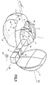
- This module 1 comprises two light sources 2 arranged to produce light for a code beam. Each of these sources 2 comprises an LED, and is associated with a collector 3.
- These LEDs 2 may be single-chip or multi-chip.
- These LEDs 2 are arranged to emit light along a common main direction, indicated by the arrows Da on the figure 1 .
- the collectors 3 are, in the example described, ellipsoid portion mirrors, each LED being placed on one of the foci of the associated collector 3.
- collectors 3 are joined and can, if desired, be made on a common part.
- the beam produced by the LEDs 2 contributes to the vehicle code illumination function, as further explained below.
- a projection lens 5 is disposed at the front of the collectors 3, substantially centered on a focus of these collectors 3.
- This lens 5 has an optical axis X-X.
- the LEDs 2 are arranged on either side of this axis X-X.
- the folder 12 has a code cutoff edge arranged to produce a code cut in the beam generated by the LEDs 2.
- the folder 12 comprises a slice 16 on which is formed said reflective lateral facet 14, this slice 16 being substantially perpendicular to the cutoff edge 15 code.
- This facet 14 is, in the example described, plane.
- the module 1 has an optical axis coincident with the optical axis X-X of the projection lens, and the folder 12 is arranged to be movable substantially perpendicularly to the optical axis X-X of the module.
- the module 1 is arranged so that the folder 12 can perform a displacement only in translation, without the possibility of rotation.
- the light source 10 associated with the reflecting facet 14 is arranged to participate in the production of the anti-glare complement beam, or ADB. This source 10 is insufficient to produce a road beam.
- the module 1 comprises another light source 20, also an LED, arranged to participate in the production of a road beam.
- the two LEDs 10 and 20 are lit together.
- the LED 20 is off.
- This LED 20 route can be of variable light intensity and participate in a tracking function, when the folder 12 is moved, as explained below.
- the light source 20 associated with the road beam is of lower light power than the light source 15 associated with the anti-glare complement beam.
- This light source 20 associated more clearly with the road beam cooperates with a dedicated collector 21 which reflects light from this light source.
- the folder 12 is disposed below a horizontal plane P passing through the optical axis XX of the lens 5.
- the LEDs 10 and 20 have respective main directions of emission Db and Dc projection on the lateral axis of displacement of the bender 12, opposite signs.
- the directions of emission Da, on the one hand, and Db and Dc, on the other hand, are substantially perpendicular.
- angles for example, of about 5 ° between these transmission directions.
- LEDs 10 and 20 are behind the LEDs 2.
- the collectors 11 and 21 are, in the example described, in ellipsoid portion, and extend on either side of the X-X axis, under the collectors 3 dedicated to the code function.
- the sources 10 and 20 are each placed at a focus of the associated collector 11 and 21.
- the folder 12 can be moved by means of a stepping motor 22, or alternatively by a piezoelectric motor for example.
- the folder 12 may for example be made of aluminized plastic or metal.
- This support 24 which can serve as a heat sink, has a constriction 25 between the LEDs 2, on the one hand, and the LEDs 10 and 20, as can be seen on the figure 2 . This makes it possible to thermally decouple these two groups of LEDs, and thus obtain better performance for the LEDs.
- the support 24 is preferably made of a heat-conducting material, for example metal or ceramic, and provided with fins intended to increase the exchange surface with air so as to serve as a cooling device for the various sources of heat. semiconductor light.
- the folder 12 with the reflective facet 14 has the role of doubling (the reflection coefficient near) the intensities in the vicinity of the cutoff edges of the beam, the latter being 'folded' on itself.
- the maximum illumination is at most equal to 2 (E1 + E2 + E3), in practice slightly less if the two maximum concentration spots generated by the reflections on each of the two upper and lateral faces are disjoint, which occurs when the folder 12 is located in an intermediate position between the ADB function and code.
- the module 1 can be associated with a camera for example placed at the front of the vehicle, and which can detect the presence of a third-party vehicle traveling in the opposite direction on the opposite lane (left) and its position (vertical and horizontal ). The information from the camera can be used to control the movements of the folder 12.
Applications Claiming Priority (1)
| Application Number | Priority Date | Filing Date | Title |
|---|---|---|---|
| FR1157850A FR2979688A1 (fr) | 2011-09-05 | 2011-09-05 | Module optique pour dispositif de signalisation et/ou d'eclairage |
Publications (1)
| Publication Number | Publication Date |
|---|---|
| EP2565530A1 true EP2565530A1 (de) | 2013-03-06 |
Family
ID=46727156
Family Applications (1)
| Application Number | Title | Priority Date | Filing Date |
|---|---|---|---|
| EP20120182805 Withdrawn EP2565530A1 (de) | 2011-09-05 | 2012-09-03 | Optisches Modul für Vorrichtung zur Signalisierung und/oder Beleuchtung |
Country Status (2)
| Country | Link |
|---|---|
| EP (1) | EP2565530A1 (de) |
| FR (1) | FR2979688A1 (de) |
Cited By (3)
| Publication number | Priority date | Publication date | Assignee | Title |
|---|---|---|---|---|
| CN106641964A (zh) * | 2017-01-19 | 2017-05-10 | 上海小糸车灯有限公司 | 一种具有adb功能的led光源远近光一体车灯模组 |
| EP2796773A3 (de) * | 2013-04-22 | 2018-01-03 | Koito Manufacturing Co., Ltd. | Fahrzeugscheinwerfer |
| EP3708904A1 (de) * | 2019-03-14 | 2020-09-16 | Valeo Vision | Leuchtvorrichtung, die die beleuchteten flächen von mindestens zwei kollektoren abbildet |
Citations (12)
| Publication number | Priority date | Publication date | Assignee | Title |
|---|---|---|---|---|
| DE102006042749A1 (de) | 2005-09-13 | 2007-03-29 | Koito Mfg. Co., Ltd. | Leuchteinheit für einen Fahrzeugscheinwerfer |
| DE102006042750A1 (de) | 2005-09-13 | 2007-03-29 | Koito Mfg. Co., Ltd. | Leuchteneinheit für einen Fahrzeugscheinwerfer |
| DE102006051029A1 (de) | 2005-10-25 | 2007-07-12 | Visteon Global Technologies, Inc., Van Buren | Bifunktionaler LED-Scheinwerfer |
| EP2196727A1 (de) | 2008-12-09 | 2010-06-16 | Koito Manufacturing Co., Ltd. | Fahrzeugausleuchtungslampe |
| EP2196726A1 (de) | 2008-12-09 | 2010-06-16 | Koito Manufacturing Co., Ltd. | Fahrzeugausleuchtungslampe |
| FR2940403A1 (fr) | 2008-12-19 | 2010-06-25 | Valeo Vision Sas | Dispositif d'eclairage pour projecteur de vehicule assurant plusieurs fonctions d'eclairage ou une fonction variable avec une seule source lumineuse |
| FR2942020A1 (fr) * | 2009-02-12 | 2010-08-13 | Automotive Lighting Reutlingen | Module de projection pour un projecteur de vehicule automobile |
| US20110141753A1 (en) | 2009-12-16 | 2011-06-16 | Koito Manufacturing Co., Ltd. | Vehicle headlamp |
| EP2341281A1 (de) * | 2009-12-08 | 2011-07-06 | Valeo Vision | Optisches Modul zur Erzeugung eines Code-Lichtstrahls und eines selektiven Lichtstrahls |
| WO2011086969A1 (ja) | 2010-01-12 | 2011-07-21 | 株式会社小糸製作所 | 車両用ヘッドランプ |
| EP2354644A1 (de) | 2010-02-05 | 2011-08-10 | Koito Manufacturing Co., Ltd. | Fahrzeugscheinwerfer |
| EP2418121A2 (de) * | 2010-08-09 | 2012-02-15 | Koito Manufacturing Co., Ltd. | Fahrzeugscheinwerfer |
-
2011
- 2011-09-05 FR FR1157850A patent/FR2979688A1/fr active Pending
-
2012
- 2012-09-03 EP EP20120182805 patent/EP2565530A1/de not_active Withdrawn
Patent Citations (12)
| Publication number | Priority date | Publication date | Assignee | Title |
|---|---|---|---|---|
| DE102006042749A1 (de) | 2005-09-13 | 2007-03-29 | Koito Mfg. Co., Ltd. | Leuchteinheit für einen Fahrzeugscheinwerfer |
| DE102006042750A1 (de) | 2005-09-13 | 2007-03-29 | Koito Mfg. Co., Ltd. | Leuchteneinheit für einen Fahrzeugscheinwerfer |
| DE102006051029A1 (de) | 2005-10-25 | 2007-07-12 | Visteon Global Technologies, Inc., Van Buren | Bifunktionaler LED-Scheinwerfer |
| EP2196727A1 (de) | 2008-12-09 | 2010-06-16 | Koito Manufacturing Co., Ltd. | Fahrzeugausleuchtungslampe |
| EP2196726A1 (de) | 2008-12-09 | 2010-06-16 | Koito Manufacturing Co., Ltd. | Fahrzeugausleuchtungslampe |
| FR2940403A1 (fr) | 2008-12-19 | 2010-06-25 | Valeo Vision Sas | Dispositif d'eclairage pour projecteur de vehicule assurant plusieurs fonctions d'eclairage ou une fonction variable avec une seule source lumineuse |
| FR2942020A1 (fr) * | 2009-02-12 | 2010-08-13 | Automotive Lighting Reutlingen | Module de projection pour un projecteur de vehicule automobile |
| EP2341281A1 (de) * | 2009-12-08 | 2011-07-06 | Valeo Vision | Optisches Modul zur Erzeugung eines Code-Lichtstrahls und eines selektiven Lichtstrahls |
| US20110141753A1 (en) | 2009-12-16 | 2011-06-16 | Koito Manufacturing Co., Ltd. | Vehicle headlamp |
| WO2011086969A1 (ja) | 2010-01-12 | 2011-07-21 | 株式会社小糸製作所 | 車両用ヘッドランプ |
| EP2354644A1 (de) | 2010-02-05 | 2011-08-10 | Koito Manufacturing Co., Ltd. | Fahrzeugscheinwerfer |
| EP2418121A2 (de) * | 2010-08-09 | 2012-02-15 | Koito Manufacturing Co., Ltd. | Fahrzeugscheinwerfer |
Cited By (6)
| Publication number | Priority date | Publication date | Assignee | Title |
|---|---|---|---|---|
| EP2796773A3 (de) * | 2013-04-22 | 2018-01-03 | Koito Manufacturing Co., Ltd. | Fahrzeugscheinwerfer |
| CN106641964A (zh) * | 2017-01-19 | 2017-05-10 | 上海小糸车灯有限公司 | 一种具有adb功能的led光源远近光一体车灯模组 |
| EP3708904A1 (de) * | 2019-03-14 | 2020-09-16 | Valeo Vision | Leuchtvorrichtung, die die beleuchteten flächen von mindestens zwei kollektoren abbildet |
| FR3093789A1 (fr) * | 2019-03-14 | 2020-09-18 | Valeo Vision | Dispositif lumineux imageant les surfaces eclairees d’au moins deux collecteurs |
| US11022266B2 (en) | 2019-03-14 | 2021-06-01 | Valeo Vision | Luminous device imaging the lit surfaces of at least two collectors |
| EP4235024A3 (de) * | 2019-03-14 | 2023-09-13 | Valeo Vision | Leuchtvorrichtung, die die beleuchteten flächen von mindestens zwei kollektoren abbildet |
Also Published As
| Publication number | Publication date |
|---|---|
| FR2979688A1 (fr) | 2013-03-08 |
Similar Documents
| Publication | Publication Date | Title |
|---|---|---|
| EP2607165B1 (de) | Beleuchtungsmodul mit zumindest zwei im wesentlich senkrecht zueinander angeordneten Lichtquellen | |
| EP3002504A2 (de) | Leuchtmodul zur beleuchtung und/oder signalisierung für kraftfahrzeug | |
| FR3009366A1 (fr) | Projecteur et systeme d'eclairage notamment pour vehicule automobile | |
| FR2963589A1 (fr) | Systeme d'eclairage pour vehicule | |
| EP2607164B1 (de) | Leuchtmodul zur Erzeugung von verflochtenen bandförmigen Leuchtbereichen | |
| FR2995967A1 (fr) | Module d'eclairage, notamment pour vehicule automobile | |
| FR2982929A1 (fr) | Dispositif d'emission de lumiere pour projecteur de vehicule automobile | |
| EP3521692B1 (de) | Bifunktions-leuchtmodul mit gemeinsamer beleuchteter fläche | |
| EP2565530A1 (de) | Optisches Modul für Vorrichtung zur Signalisierung und/oder Beleuchtung | |
| EP2416061A2 (de) | Beleuchtungsmodul mit Abschaltfunktion mit einem Parabolreflektor, der auf einem elliptischen Reflektor angebracht ist | |
| EP2436968B1 (de) | Vorrichtung zur Ausstrahlung von Licht für einen Autoscheinwerfer | |
| EP3124853A1 (de) | Vorrichtung zur beleuchtung und/oder signalisierung für kraftfahrzeug | |
| EP3124856B1 (de) | Beleuchtungsvorrichtung für kraftfahrzeug | |
| EP2853804B1 (de) | Beleuchtungs- und/oder signalisierungsmodul mit mehreren drehbaren optischen systemen | |
| EP1471305A1 (de) | Beleuchtungseinrichtung für Kfz-Scheinwerfer | |
| EP2799763B1 (de) | Fahrzeugscheinwerfer | |
| EP2472176A2 (de) | Beleuchtungs- und/oder Signalisierungsvorrichtung, insbesondere für Kraftfahrzeug | |
| FR3025290B1 (fr) | Module d'eclairage multifonction pour vehicule automobile | |
| FR2965325A1 (fr) | Dispositif d'eclairage et de signalisation d'un vehicule automobile et procede de fonctionnement d'un tel dispositif | |
| WO2024061970A1 (fr) | Module lumineux | |
| FR3103252A1 (fr) | Module d’eclairage pour vehicule a coupure modulable entre conduite a gauche et conduite a droite | |
| FR3038694A1 (fr) | Dispositif lumineux configure pour emettre un faisceau lumineux segmente, notamment pour vehicule automobile, et projecteur muni d'un tel dispositif. | |
| EP3141803B1 (de) | Leuchtmodul zur beleuchtung und/oder signalisierung für kraftfahrzeug | |
| EP2354645B1 (de) | Optische Vorrichtung, insbesondere für Kraftfahrzeug | |
| FR3062706A1 (fr) | Reflecteur multifonction par deplacement |
Legal Events
| Date | Code | Title | Description |
|---|---|---|---|
| PUAI | Public reference made under article 153(3) epc to a published international application that has entered the european phase |
Free format text: ORIGINAL CODE: 0009012 |
|
| AK | Designated contracting states |
Kind code of ref document: A1 Designated state(s): AL AT BE BG CH CY CZ DE DK EE ES FI FR GB GR HR HU IE IS IT LI LT LU LV MC MK MT NL NO PL PT RO RS SE SI SK SM TR |
|
| AX | Request for extension of the european patent |
Extension state: BA ME |
|
| 17P | Request for examination filed |
Effective date: 20130807 |
|
| RBV | Designated contracting states (corrected) |
Designated state(s): AL AT BE BG CH CY CZ DE DK EE ES FI FR GB GR HR HU IE IS IT LI LT LU LV MC MK MT NL NO PL PT RO RS SE SI SK SM TR |
|
| 17Q | First examination report despatched |
Effective date: 20200123 |
|
| STAA | Information on the status of an ep patent application or granted ep patent |
Free format text: STATUS: THE APPLICATION IS DEEMED TO BE WITHDRAWN |
|
| 18D | Application deemed to be withdrawn |
Effective date: 20200603 |