EP2565530A1 - Optical module for a signalling and/or lighting device - Google Patents
Optical module for a signalling and/or lighting device Download PDFInfo
- Publication number
- EP2565530A1 EP2565530A1 EP20120182805 EP12182805A EP2565530A1 EP 2565530 A1 EP2565530 A1 EP 2565530A1 EP 20120182805 EP20120182805 EP 20120182805 EP 12182805 A EP12182805 A EP 12182805A EP 2565530 A1 EP2565530 A1 EP 2565530A1
- Authority
- EP
- European Patent Office
- Prior art keywords
- light
- light source
- module according
- road
- folder
- Prior art date
- Legal status (The legal status is an assumption and is not a legal conclusion. Google has not performed a legal analysis and makes no representation as to the accuracy of the status listed.)
- Withdrawn
Links
Images


Classifications
-
- F—MECHANICAL ENGINEERING; LIGHTING; HEATING; WEAPONS; BLASTING
- F21—LIGHTING
- F21S—NON-PORTABLE LIGHTING DEVICES; SYSTEMS THEREOF; VEHICLE LIGHTING DEVICES SPECIALLY ADAPTED FOR VEHICLE EXTERIORS
- F21S41/00—Illuminating devices specially adapted for vehicle exteriors, e.g. headlamps
- F21S41/60—Illuminating devices specially adapted for vehicle exteriors, e.g. headlamps characterised by a variable light distribution
- F21S41/68—Illuminating devices specially adapted for vehicle exteriors, e.g. headlamps characterised by a variable light distribution by acting on screens
- F21S41/683—Illuminating devices specially adapted for vehicle exteriors, e.g. headlamps characterised by a variable light distribution by acting on screens by moving screens
-
- F—MECHANICAL ENGINEERING; LIGHTING; HEATING; WEAPONS; BLASTING
- F21—LIGHTING
- F21S—NON-PORTABLE LIGHTING DEVICES; SYSTEMS THEREOF; VEHICLE LIGHTING DEVICES SPECIALLY ADAPTED FOR VEHICLE EXTERIORS
- F21S41/00—Illuminating devices specially adapted for vehicle exteriors, e.g. headlamps
- F21S41/10—Illuminating devices specially adapted for vehicle exteriors, e.g. headlamps characterised by the light source
- F21S41/14—Illuminating devices specially adapted for vehicle exteriors, e.g. headlamps characterised by the light source characterised by the type of light source
- F21S41/141—Light emitting diodes [LED]
- F21S41/147—Light emitting diodes [LED] the main emission direction of the LED being angled to the optical axis of the illuminating device
- F21S41/148—Light emitting diodes [LED] the main emission direction of the LED being angled to the optical axis of the illuminating device the main emission direction of the LED being perpendicular to the optical axis
-
- F—MECHANICAL ENGINEERING; LIGHTING; HEATING; WEAPONS; BLASTING
- F21—LIGHTING
- F21S—NON-PORTABLE LIGHTING DEVICES; SYSTEMS THEREOF; VEHICLE LIGHTING DEVICES SPECIALLY ADAPTED FOR VEHICLE EXTERIORS
- F21S41/00—Illuminating devices specially adapted for vehicle exteriors, e.g. headlamps
- F21S41/30—Illuminating devices specially adapted for vehicle exteriors, e.g. headlamps characterised by reflectors
- F21S41/32—Optical layout thereof
- F21S41/321—Optical layout thereof the reflector being a surface of revolution or a planar surface, e.g. truncated
-
- F—MECHANICAL ENGINEERING; LIGHTING; HEATING; WEAPONS; BLASTING
- F21—LIGHTING
- F21S—NON-PORTABLE LIGHTING DEVICES; SYSTEMS THEREOF; VEHICLE LIGHTING DEVICES SPECIALLY ADAPTED FOR VEHICLE EXTERIORS
- F21S41/00—Illuminating devices specially adapted for vehicle exteriors, e.g. headlamps
- F21S41/30—Illuminating devices specially adapted for vehicle exteriors, e.g. headlamps characterised by reflectors
- F21S41/32—Optical layout thereof
- F21S41/36—Combinations of two or more separate reflectors
- F21S41/365—Combinations of two or more separate reflectors successively reflecting the light
-
- F—MECHANICAL ENGINEERING; LIGHTING; HEATING; WEAPONS; BLASTING
- F21—LIGHTING
- F21S—NON-PORTABLE LIGHTING DEVICES; SYSTEMS THEREOF; VEHICLE LIGHTING DEVICES SPECIALLY ADAPTED FOR VEHICLE EXTERIORS
- F21S41/00—Illuminating devices specially adapted for vehicle exteriors, e.g. headlamps
- F21S41/40—Illuminating devices specially adapted for vehicle exteriors, e.g. headlamps characterised by screens, non-reflecting members, light-shielding members or fixed shades
- F21S41/43—Illuminating devices specially adapted for vehicle exteriors, e.g. headlamps characterised by screens, non-reflecting members, light-shielding members or fixed shades characterised by the shape thereof
-
- F—MECHANICAL ENGINEERING; LIGHTING; HEATING; WEAPONS; BLASTING
- F21—LIGHTING
- F21S—NON-PORTABLE LIGHTING DEVICES; SYSTEMS THEREOF; VEHICLE LIGHTING DEVICES SPECIALLY ADAPTED FOR VEHICLE EXTERIORS
- F21S41/00—Illuminating devices specially adapted for vehicle exteriors, e.g. headlamps
- F21S41/60—Illuminating devices specially adapted for vehicle exteriors, e.g. headlamps characterised by a variable light distribution
- F21S41/67—Illuminating devices specially adapted for vehicle exteriors, e.g. headlamps characterised by a variable light distribution by acting on reflectors
- F21S41/675—Illuminating devices specially adapted for vehicle exteriors, e.g. headlamps characterised by a variable light distribution by acting on reflectors by moving reflectors
Definitions
- the invention relates in particular to an optical module, in particular for signaling and / or lighting device for a motor vehicle.
- the document DE 10 2006 042 749 A1 discloses a vehicle headlighting device comprising an LED light source, an elliptical reflector in a half-space with two foci.
- the LED source is placed at the first focus of the reflector near the reflector.
- the light emitted by the LED source is reflected by the reflector towards its second focus where a so-called folding reflective surface is positioned.
- This reflecting surface has an edge on the reflector side and an edge on the opposite side of the reflector. These edges are called "cut edges”.
- a portion of the light beam reflected by the reflector encounters the reflecting surface and is reflected in accordance with its angle of incidence on the surface. Another part of the light beam passes over the cutoff edge (s) and is not deflected by the reflecting surface.
- the cutoff edge thus defines a boundary between the portion of the reflected beam and thus deflected and the nonreflected portion.
- a lens is positioned behind the reflective surface so that its focus corresponds to that of the elliptical reflector.
- the reflective surface with its cutoff edge (s) is called a folder because it deflects or "bends" part of the bundle to form a cutoff at the beam emitted by the lens.
- the folder is movable along an axis parallel to the axis optical reflector. This mobility ensures the function "road” or "High Beam” and the function "code” or "Low Beam".
- the document DE 10 2006 051 029 A1 discloses a device similar to that described above where the "folding” is movable along a vertical axis and an axis parallel to the optical axis of the elliptical reflector. These two movements make it possible to ensure the function "road” or “High Beam” and the function "code” or “Low Beam”.
- the document DE 10 2006 042 750 A1 discloses a device similar to those described above wherein a "folder” is vertically movable and a vertical screen is movably arranged vertically as well. This device ensures the functions "road” and “code” with a single light source and moving the vertical screen also allows to vary the light intensity in the bottom of the beam of the projector.
- Patent applications EP 2,354,644 , WO 11086969 , US 2011141753 , EP 2 196 727 and EP 2 196 726 describe other LED devices.
- the patent application FR 2 940 403 discloses a projector lighting device, especially a vehicle, comprising: a reflector having a first focus, a second focus and an optical axis passing through the first and second focus; a light source located near the first focus of the reflector so that the light rays emitted by the light source are reflected by the reflector approximately to its second focus; a first optical element comprising a focus and an optical axis, the focus being located near the second focus of the reflector, the first optical element being able to project the light rays emitted by the source and reflected by the reflector in a beam along its axis; optical; a second optical element comprising a generally planar surface having an area near the second focus of the reflector so as to receive at an angle of incidence the light rays emitted by the source and reflected by the reflector; wherein the second optical element is movable in the plane of its surface transverse to the optical axis of the reflector so as to move said area out of the light
- the present invention aims in particular to improve the devices described above, particularly with regard to the sufficient level of performance of the ADB and route functions.
- the invention thus proposes to associate with the light source for the anti-glare function, or ADB, a dedicated collector. This makes it possible to effectively use the cutting edge of the folder in this anti-glare function and to increase the luminous flux in ADB.
- the folder comprises a code cut edge arranged to produce a code cut.
- the folder comprises a slice on which is formed said reflective lateral facet, this slice being in particular substantially perpendicular to the cutoff edge code.
- the module has an optical axis particularly coincident with the optical axis of the projection lens, and the folder is arranged to be movable substantially perpendicular to the optical axis of the module.
- the module is arranged in such a way that the folder can perform a displacement solely in translation, without any combination with other movements, in particular rotation, in order to remain mechanically simple while allowing the necessary displacements of the vertical cutout to be made without rotate the entire module.
- the light source associated with the reflective facet is arranged to participate primarily in the anti-glare complement beam, or ADB.
- the module may include another light source arranged to participate in the production of a road beam.
- the light source associated with the road beam is of lower light output than the light source associated with the anti-glare complement beam. Preferably, it is of similar or even higher luminance.
- this light source associated with the road beam cooperates with a dedicated collector which reflects light from this light source.
- the ADB LED and ADB reflector assembly when the vertical cutoff is on the optical axis, the ADB LED and ADB reflector assembly illuminates a little less than the upper half of the lens; when the folder is ejected in road mode, the ADB LED and ADB reflector assembly illuminates slightly more than a quarter of the lens; by lighting a second source, namely the road LED, with its specific cavity, we can then illuminate twice this area from where, in terms of intensity, even more en route than ADB with folder in optimal position, with vertical cut in the axis.
- the two light sources are arranged on a common support, this support possibly being able to serve as a heat sink.
- the light source associated with the reflective lateral facet is arranged to participate in the production of both the anti-glare complement beam and a driving beam, in particular this light source may have a variable light output. .
- ADB LED for example dual luminance
- 'wattage' at 50%, for example, in ADB mode, and at full power in the road mode. In this way, the behavior and interesting intensity ratios of the two-LED system are reproduced.
- the module comprises at least one light source arranged to produce light for a code beam, the number of light sources associated with this code beam may be greater than or equal to two.
- the main light emission directions respectively of the light sources associated with the coded beam and the complementary anti-glare beam are substantially perpendicular.
- all the light sources of the module are carried by a common support. This allows in particular to simplify the architecture of the device.
- the folder is disposed below a horizontal plane passing through the optical axis of the lens, optionally the reflective lateral surface extends to this horizontal plane.
- the module is arranged in such a way that the road beam can be superimposed on the anti-glare complement beam so as to provide maximum illumination at the center of the overall beam produced by the module.
- the folder is movable according to a characteristic information of the driving scene, including the presence of a user of the road such as a cruising vehicle or a vehicle traveling in front.
- the invention can thus make it possible to track a vehicle with a non-glare beam.
- This information of the driving scene can come for example from a camera or a radar installed on the vehicle.
- the invention also relates to a lighting device for a motor vehicle, comprising at least one aforementioned module.
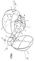
- This module 1 comprises two light sources 2 arranged to produce light for a code beam. Each of these sources 2 comprises an LED, and is associated with a collector 3.
- These LEDs 2 may be single-chip or multi-chip.
- These LEDs 2 are arranged to emit light along a common main direction, indicated by the arrows Da on the figure 1 .
- the collectors 3 are, in the example described, ellipsoid portion mirrors, each LED being placed on one of the foci of the associated collector 3.
- collectors 3 are joined and can, if desired, be made on a common part.
- the beam produced by the LEDs 2 contributes to the vehicle code illumination function, as further explained below.
- a projection lens 5 is disposed at the front of the collectors 3, substantially centered on a focus of these collectors 3.
- This lens 5 has an optical axis X-X.
- the LEDs 2 are arranged on either side of this axis X-X.
- the folder 12 has a code cutoff edge arranged to produce a code cut in the beam generated by the LEDs 2.
- the folder 12 comprises a slice 16 on which is formed said reflective lateral facet 14, this slice 16 being substantially perpendicular to the cutoff edge 15 code.
- This facet 14 is, in the example described, plane.
- the module 1 has an optical axis coincident with the optical axis X-X of the projection lens, and the folder 12 is arranged to be movable substantially perpendicularly to the optical axis X-X of the module.
- the module 1 is arranged so that the folder 12 can perform a displacement only in translation, without the possibility of rotation.
- the light source 10 associated with the reflecting facet 14 is arranged to participate in the production of the anti-glare complement beam, or ADB. This source 10 is insufficient to produce a road beam.
- the module 1 comprises another light source 20, also an LED, arranged to participate in the production of a road beam.
- the two LEDs 10 and 20 are lit together.
- the LED 20 is off.
- This LED 20 route can be of variable light intensity and participate in a tracking function, when the folder 12 is moved, as explained below.
- the light source 20 associated with the road beam is of lower light power than the light source 15 associated with the anti-glare complement beam.
- This light source 20 associated more clearly with the road beam cooperates with a dedicated collector 21 which reflects light from this light source.
- the folder 12 is disposed below a horizontal plane P passing through the optical axis XX of the lens 5.
- the LEDs 10 and 20 have respective main directions of emission Db and Dc projection on the lateral axis of displacement of the bender 12, opposite signs.
- the directions of emission Da, on the one hand, and Db and Dc, on the other hand, are substantially perpendicular.
- angles for example, of about 5 ° between these transmission directions.
- LEDs 10 and 20 are behind the LEDs 2.
- the collectors 11 and 21 are, in the example described, in ellipsoid portion, and extend on either side of the X-X axis, under the collectors 3 dedicated to the code function.
- the sources 10 and 20 are each placed at a focus of the associated collector 11 and 21.
- the folder 12 can be moved by means of a stepping motor 22, or alternatively by a piezoelectric motor for example.
- the folder 12 may for example be made of aluminized plastic or metal.
- This support 24 which can serve as a heat sink, has a constriction 25 between the LEDs 2, on the one hand, and the LEDs 10 and 20, as can be seen on the figure 2 . This makes it possible to thermally decouple these two groups of LEDs, and thus obtain better performance for the LEDs.
- the support 24 is preferably made of a heat-conducting material, for example metal or ceramic, and provided with fins intended to increase the exchange surface with air so as to serve as a cooling device for the various sources of heat. semiconductor light.
- the folder 12 with the reflective facet 14 has the role of doubling (the reflection coefficient near) the intensities in the vicinity of the cutoff edges of the beam, the latter being 'folded' on itself.
- the maximum illumination is at most equal to 2 (E1 + E2 + E3), in practice slightly less if the two maximum concentration spots generated by the reflections on each of the two upper and lateral faces are disjoint, which occurs when the folder 12 is located in an intermediate position between the ADB function and code.
- the module 1 can be associated with a camera for example placed at the front of the vehicle, and which can detect the presence of a third-party vehicle traveling in the opposite direction on the opposite lane (left) and its position (vertical and horizontal ). The information from the camera can be used to control the movements of the folder 12.
Abstract
Description
L'invention concerne notamment un module optique, notamment pour dispositif de signalisation et/ou d'éclairage pour véhicule automobile.The invention relates in particular to an optical module, in particular for signaling and / or lighting device for a motor vehicle.
Il existe un besoin, dans le domaine de l'automobile, de pouvoir illuminer la route devant soi en "mode éclairage route partiel", à savoir générer dans un faisceau route une ou plusieurs plages sombres correspondant aux endroits où sont présents des véhicules venant en sens inverse ou des véhicules roulant devant, de manière à éviter l'éblouissement des autres conducteurs tout en éclairant la route dans sa plus grande surface. Une telle fonction est appelée ADB (Adaptive Driving Beam en anglais) ou encore « faisceau sélectif ».There is a need, in the field of the automobile, to be able to illuminate the road ahead in "partial road lighting mode", namely to generate in a beam road one or more dark beaches corresponding to the locations where there are vehicles coming in. in the opposite direction or vehicles driving ahead, so as to avoid dazzling other drivers while illuminating the road in its larger area. Such a function is called ADB ( Adaptive Driving Beam in English) or "selective beam".
Le document
Le document
Le document
Les demandes de brevet
La demande de brevet
La présente invention vise notamment à améliorer les dispositifs décrits ci-dessus, notamment en ce qui concerne le niveau suffisant en performances des fonctions ADB et route.The present invention aims in particular to improve the devices described above, particularly with regard to the sufficient level of performance of the ADB and route functions.
L'invention a ainsi pour objet un module optique, notamment pour dispositif de signalisation et/ou d'éclairage pour véhicule automobile, ce module comportant :
- au moins une source de lumière,
- un collecteur associé à cette source de lumière, ce collecteur étant agencé pour réfléchir de la lumière provenant de ladite source de lumière,
- une plieuse mobile par rapport à ladite source de lumière, et comportant une facette latérale réfléchissante, cette plieuse mobile pouvant occuper au moins une position anti-éblouissement dans laquelle de la lumière provenant de la source lumineuse et réfléchie par le collecteur puis par cette facette de la plieuse, servent à créer un faisceau lumineux de complément anti-éblouissement présentant une coupure ayant au moins un segment sensiblement vertical,
- un élément optique de projection tel qu'une lentille, placé sur le trajet de la lumière provenant de la facette latérale réfléchissante.
- at least one light source,
- a collector associated with this light source, this collector being arranged to reflect light from said light source,
- a bender movable relative to said light source, and having a reflective lateral facet, this mobile bender can occupy at least one anti-glare position in which light from the light source and reflected by the collector and then by this facet of the folder, serve to create an anti-glare complement light beam having a cutoff having at least one substantially vertical segment,
- an optical projection element such as a lens, placed in the path of light coming from the reflective lateral facet.
L'invention propose ainsi d'associer à la source de lumière pour la fonction anti-éblouissement, ou ADB, un collecteur dédié. Ceci permet notamment d'utiliser efficacement le bord de coupure de la plieuse dans cette fonction anti-éblouissement et d'augmenter le flux lumineux en ADB.The invention thus proposes to associate with the light source for the anti-glare function, or ADB, a dedicated collector. This makes it possible to effectively use the cutting edge of the folder in this anti-glare function and to increase the luminous flux in ADB.
De préférence, la plieuse comporte un bord de coupure code agencé pour produire une coupure code.Preferably, the folder comprises a code cut edge arranged to produce a code cut.
De préférence encore, la plieuse comporte une tranche sur laquelle est formée ladite facette latérale réfléchissante, cette tranche étant notamment sensiblement perpendiculaire au bord de coupure code.More preferably, the folder comprises a slice on which is formed said reflective lateral facet, this slice being in particular substantially perpendicular to the cutoff edge code.
Dans un exemple de mise en oeuvre de l'invention, le module présente un axe optique notamment confondu avec l'axe optique de la lentille de projection, et la plieuse est agencée pour être mobile sensiblement perpendiculairement à l'axe optique du module.In an exemplary implementation of the invention, the module has an optical axis particularly coincident with the optical axis of the projection lens, and the folder is arranged to be movable substantially perpendicular to the optical axis of the module.
Avantageusement le module est agencé de manière à ce que la plieuse puisse accomplir un déplacement uniquement en translation, sans combinaison avec d'autres mouvements, notamment de rotation, afin de rester mécaniquement simple tout en permettant de réaliser les déplacements nécessaires de la coupure verticale sans faire tourner l'ensemble du module.Advantageously, the module is arranged in such a way that the folder can perform a displacement solely in translation, without any combination with other movements, in particular rotation, in order to remain mechanically simple while allowing the necessary displacements of the vertical cutout to be made without rotate the entire module.
Si on le souhaite, la source de lumière associée à la facette réfléchissante est agencée pour participer essentiellement du faisceau de complément anti-éblouissement, ou ADB.If desired, the light source associated with the reflective facet is arranged to participate primarily in the anti-glare complement beam, or ADB.
Par exemple, le module peut comporter une autre source lumineuse agencée pour participer à la production d'un faisceau route.For example, the module may include another light source arranged to participate in the production of a road beam.
Le cas échéant, la source de lumière associée au faisceau route est de plus faible puissance lumineuse que la source de lumière associée au faisceau de complément anti-éblouissement. De préférence, elle est de luminance similaire voire supérieure.Where appropriate, the light source associated with the road beam is of lower light output than the light source associated with the anti-glare complement beam. Preferably, it is of similar or even higher luminance.
Avantageusement cette source de lumière associée au faisceau route coopère avec un collecteur dédié qui réfléchit de la lumière provenant de cette source de lumière.Advantageously this light source associated with the road beam cooperates with a dedicated collector which reflects light from this light source.
Ceci permet de compenser la perte en effet plieuse verticale dans le faisceau route, en permettant l'utilisation optimale de la surface de la lentille.This makes it possible to compensate for the loss of vertical bending effect in the road beam, while allowing the optimal use of the surface of the lens.
En effet, lorsque la coupure verticale est sur l'axe optique, l'ensemble LED ADB et réflecteur ADB illumine un peu moins de la moitié supérieure de la lentille ; lorsque la plieuse est éjectée en mode route, l'ensemble LED ADB et réflecteur ADB illumine un peu plus du quart de la lentille ; en allumant une seconde source, à savoir la LED route, avec sa cavité spécifique, on peut alors illuminer deux fois cette surface d'où, en terme d'intensité, encore plus en route qu'en ADB avec plieuse en position optimale, avec coupure verticale dans l'axe.In fact, when the vertical cutoff is on the optical axis, the ADB LED and ADB reflector assembly illuminates a little less than the upper half of the lens; when the folder is ejected in road mode, the ADB LED and ADB reflector assembly illuminates slightly more than a quarter of the lens; by lighting a second source, namely the road LED, with its specific cavity, we can then illuminate twice this area from where, in terms of intensity, even more en route than ADB with folder in optimal position, with vertical cut in the axis.
Dans un exemple de mise en oeuvre de l'invention, les deux sources de lumière sont disposées sur un support commun, ce support pouvant éventuellement servir de dissipateur de chaleur.In an exemplary implementation of the invention, the two light sources are arranged on a common support, this support possibly being able to serve as a heat sink.
Dans une variante, la source de lumière associée à la facette latérale réfléchissante est agencée pour participer à la production à la fois du faisceau de complément anti-éblouissement et d'un faisceau de route, notamment cette source de lumière pouvant présenter une puissance lumineuse variable.In a variant, the light source associated with the reflective lateral facet is arranged to participate in the production of both the anti-glare complement beam and a driving beam, in particular this light source may have a variable light output. .
Par exemple, il est possible d'utiliser une LED ADB très performante, de luminance double par exemple, sous 'wattée', à 50% par exemple, en mode ADB, et à pleine puissance en mode route. De cette manière, on reproduit le comportement et les rapports d'intensités intéressants du système à deux LEDs.For example, it is possible to use a high-performance ADB LED, for example dual luminance, under 'wattage', at 50%, for example, in ADB mode, and at full power in the road mode. In this way, the behavior and interesting intensity ratios of the two-LED system are reproduced.
De préférence, le module comporte au moins une source de lumière agencée pour produire de la lumière destinée à un faisceau code, le nombre de sources de lumière associées à ce faisceau code pouvant être supérieur ou égal à deux.Preferably, the module comprises at least one light source arranged to produce light for a code beam, the number of light sources associated with this code beam may be greater than or equal to two.
De préférence encore, les directions principales d'émission de la lumière respectivement des sources de lumière associées au faisceau code et au faisceau complémentaire anti-éblouissement sont sensiblement perpendiculaires.More preferably, the main light emission directions respectively of the light sources associated with the coded beam and the complementary anti-glare beam are substantially perpendicular.
Le cas échéant, toutes les sources de lumière du module sont portées par un support commun. Ceci permet notamment de simplifier l'architecture du dispositif.If necessary, all the light sources of the module are carried by a common support. This allows in particular to simplify the architecture of the device.
Dans un exemple de mise en oeuvre de l'invention, la plieuse est disposée en dessous d'un plan horizontal passant par l'axe optique de la lentille, éventuellement la face latérale réfléchissante s'étend jusqu'à ce plan horizontal.In an exemplary implementation of the invention, the folder is disposed below a horizontal plane passing through the optical axis of the lens, optionally the reflective lateral surface extends to this horizontal plane.
De préférence, le module est agencé de manière à ce que le faisceau route puisse être superposé au faisceau de complément anti-éblouissement de manière offrir un maximum d'éclairement au centre du faisceau global produit par le module.Preferably, the module is arranged in such a way that the road beam can be superimposed on the anti-glare complement beam so as to provide maximum illumination at the center of the overall beam produced by the module.
Le cas échéant, la plieuse est déplaçable en fonction d'une information caractéristique de la scène de conduite, notamment la présence d'un usager de la route tel qu'un véhicule croisant ou un véhicule circulant devant.If necessary, the folder is movable according to a characteristic information of the driving scene, including the presence of a user of the road such as a cruising vehicle or a vehicle traveling in front.
L'invention peut ainsi permettre de faire du suivi d'un véhicule avec un faisceau non-éblouissant. Cette information de la scène de conduite peut provenir par exemple d'une caméra ou d'un radar installé sur le véhicule.The invention can thus make it possible to track a vehicle with a non-glare beam. This information of the driving scene can come for example from a camera or a radar installed on the vehicle.
L'invention a également pour objet un dispositif d'éclairage de véhicule automobile, comportant au moins un module précité.The invention also relates to a lighting device for a motor vehicle, comprising at least one aforementioned module.
L'invention a encore pour objet un procédé pour produire un éclairage de suivi d'un usager de la route, le procédé comportant les étapes suivantes :
- fournir un module précité,
- déplacer la plieuse mobile en fonction d'une information caractéristique de l'usager de la route de manière à produire un éclairage adaptatif présentant une zone anti-éblouissement qui suit cet usage de la route.
- provide a module mentioned above,
- moving the mobile folding machine according to a characteristic information of the user of the road so as to produce an adaptive lighting having an anti-glare area that follows this use of the road.
L'invention pourra être mieux comprise à la lecture de la description détaillée qui va suivre, d'un exemple de mise en oeuvre non limitatif de l'invention, et à l'examen du dessin annexé, sur lequel :
- la
figure 1 illustre, schématiquement et partiellement, différents éléments d'un module selon un exemple de mise en oeuvre de l'invention, - les
figures 2 représentent, schématiquement et partiellement, un support de LEDs du module de laet 3figure 1 , respectivement en vues de face et de côté, - les
figures 4 illustrent schématiquement le trajet de rayons lumineux dans le module de laet 5figure 1 , respectivement pour deux positions de la plieuse, et - les
figures 6 à 11 illustrent schématiquement, en fonction de la position de la plieuse, les différents faisceaux obtenus par le module de lafigure 1 , sur un écran à l'avant du module.
- the
figure 1 illustrates, schematically and partially, various elements of a module according to an exemplary implementation of the invention, - the
Figures 2 and 3 represent, schematically and partially, a support of LEDs of the module of thefigure 1 , respectively in front and side views, - the
Figures 4 and 5 schematically illustrate the path of light rays in the module of thefigure 1 respectively for two positions of the folder, and - the
Figures 6 to 11 schematically illustrate, according to the position of the folder, the different beams obtained by the module of thefigure 1 , on a screen at the front of the module.
On a représenté sur la
Ce module 1 comporte deux sources de lumière 2 agencées pour produire de la lumière destinée à un faisceau code. Chacune de ces sources 2 comporte une LED, et est associée à un collecteur 3.This module 1 comprises two
Ces LEDs 2 peuvent être à puce unique ou à puces multiples.These
Ces LEDs 2 sont disposées de manière à émettre de la lumière suivant une direction principale commune, matérialisée par les flèches Da sur la
Les collecteurs 3 sont, dans l'exemple décrit, des miroirs en portion d'ellipsoïde, chaque LED étant placée sur l'un des foyers du collecteur 3 associé.The
Ces collecteurs 3 sont jointifs et peuvent, si on le souhaite, être réalisés sur une pièce commune.These
Le faisceau produit par les LEDs 2 contribue à la fonction d'éclairage code du véhicule, comme encore expliqué plus bas.The beam produced by the
Une lentille de projection 5 est disposée à l'avant des collecteurs 3, de manière sensiblement centrée sur un foyer de ces collecteurs 3.A
Cette lentille 5 présente un axe optique X-X.This
Les LEDs 2 sont disposées de part et d'autre de cet axe X-X.The
Ce module 1 comporte en outre :
- une autre source de lumière 10, également formée d'une LED, par exemple une LED à multi-puces,
un collecteur 11 associé à cette source de lumière, ce collecteur 11 étant agencé pour réfléchir de la lumière provenant de ladite source de lumière 10,une plieuse 12 mobile par rapport à ladite source de lumière 10, suivant la direction Dp (perpendiculaire à l'axe optique X-X), et comportant une facette latérale réfléchissante 14, cette plieuse mobile 12 pouvant occuper au moins une position anti-éblouissement dans laquelle de la lumière provenant de la source lumineuse 10 et réfléchie par le collecteur 11 puispar cette facette 14 de la plieuse 12, servent à créer un faisceau lumineux de complément non-éblouissant présentant une coupure ayant au moins un segment sensiblement vertical.
- another
light source 10, also formed of an LED, for example a multi-chip LED, - a
collector 11 associated with this light source, thiscollector 11 being arranged to reflect light from saidlight source 10, - a
folder 12 movable relative to saidlight source 10, in the direction Dp (perpendicular to the optical axis XX), and having a reflectivelateral facet 14, thismobile bender 12 can occupy at least one anti-glare position in which light from thelight source 10 and reflected by thecollector 11 and by thisfacet 14 of thefolder 12, serve to create a non-glare complement light beam having a cut having at least one substantially vertical segment.
La plieuse 12 comporte un bord de coupure code 15 agencé pour produire une coupure code dans le faisceau généré par les LEDs 2.The
La plieuse 12 comporte une tranche 16 sur laquelle est formée ladite facette latérale réfléchissante 14, cette tranche 16 étant sensiblement perpendiculaire au bord 15 de coupure code.The
Cette facette 14 est, dans l'exemple décrit, plane.This
Le module 1 présente un axe optique confondu avec l'axe optique X-X de la lentille de projection, et la plieuse 12 est agencée pour être mobile sensiblement perpendiculairement à l'axe optique X-X du module.The module 1 has an optical axis coincident with the optical axis X-X of the projection lens, and the
Le module 1 est agencé de manière à ce que la plieuse 12 puisse accomplir un déplacement uniquement en translation, sans possibilité de rotation.The module 1 is arranged so that the
La source de lumière 10 associée à la facette réfléchissante 14 est agencée pour participer à la production du faisceau de complément anti-éblouissement, ou ADB. Cette source 10 est insuffisante pour produire un faisceau route.The
Le module 1 comporte une autre source lumineuse 20, également une LED, agencée pour participer à la production d'un faisceau route. Pour la production du faisceau route, les deux LEDs 10 et 20 sont allumées ensemble. Lorsque le faisceau route est désactivé, la LED 20 est éteinte. Cette LED 20 route peut être d'intensité lumineuse variable et participer à une fonction de suivi, lorsque la plieuse 12 est déplacée, comme expliqué plus loin.The module 1 comprises another
La source de lumière 20 associée au faisceau route est de plus faible puissance lumineuse que la source de lumière 15 associée au faisceau de complément anti-éblouissement.The
Cette source de lumière 20 associée plus fiquement au faisceau route coopère avec un collecteur 21 dédié qui réfléchit de la lumière provenant de cette source de lumière.This
Ceci permet de compenser la perte en portée liée à l'absence d'effet plieuse verticale dans le faisceau route, en permettant l'utilisation optimale de la surface de la lentille.This makes it possible to compensate for the loss in range related to the absence of vertical folding effect in the road beam, while allowing the optimal use of the surface of the lens.
La plieuse 12 est disposée en dessous d'un plan horizontal P passant par l'axe optique X-X de la lentille 5.The
Les LEDs 10 et 20 présentent des directions principales d'émission respectives Db et Dc de projection sur l'axe latéral de déplacement de la plieuse 12, de signes opposés.The
Les directions d'émission Da, d'une part, et Db et Dc, d'autre part, sont sensiblement perpendiculaires.The directions of emission Da, on the one hand, and Db and Dc, on the other hand, are substantially perpendicular.
Il peut éventuellement se présenter des angles par exemple d'environ 5° entre ces directions d'émission.There may be angles, for example, of about 5 ° between these transmission directions.
Les LEDs 10 et 20 sont en arrière des LEDs 2.
Les collecteurs 11 et 21 sont, dans l'exemple décrit, en portion d'ellipsoïde, et s'étendent de part et d'autre de l'axe X-X, sous les collecteurs 3 dédiés à la fonction code. Les sources 10 et 20 sont placées chacune à un foyer du collecteur associé 11 et 21.The
La plieuse 12 est déplaçable à l'aide d'un moteur pas à pas 22, ou en variante, par un moteur piézoélectrique par exemple.The
La plieuse 12 peut par exemple être fabriquée en plastique aluminé ou en métal.The
Comme illustré sur les
Ce support 24, qui peut servir de dissipateur thermique, comporte un étranglement 25 séparant les LEDs 2, d'une part, et les LEDs 10 et 20, comme on peut le voir sur la
Le support 24 est de préférence réalisé dans un matériau conducteur de la chaleur, par exemple en métal ou céramique, et muni d'ailettes destinées à augmenter la surface d'échange avec l'air afin de servir de dispositif de refroidissement des différentes sources de lumière à semi-conducteurs.The
On va maintenir expliquer plus en détail la production des faisceaux ADB et route, en référence aux
Dans une position dans laquelle la facette 14 sur la tranche 16 de la plieuse 12 sert à produire la coupure du faisceau de complément ADB :
- lorsque la coupure verticale du faisceau ADB est sensiblement dans l'axe et seule la
LED 10 de la fonction ADB est allumée (voirfigure 4 ), la zone Z du collecteur 11 correspondant aux rayons pliés (arrivant sur la facette 14) est relativement étendue, - lorsque la coupure verticale du faisceau ADB est décalée par rapport à l'axe optique, et la
LED 20 pour la fonction route est allumée (voirfigure 5 , la plieuse est davantage « éjectée » vers la position route), la zone Z du collecteur 11 correspondant aux rayons pliés (arrivant sur la facette 14) se réduit au fur et à mesure que la plieuse s'éloigne de l'axe X-X. En même temps, la zone utile Zu pour la fonction route, sur le collecteur 21, s'agrandit. Les rayons lumineux de la zone Za apportent de la lumière au voisinage de l'axe optique, entre cet axe et la coupure verticale de l'ADB.
- when the vertical cut of the ADB beam is substantially in the axis and only the
LED 10 of the ADB function is on (seefigure 4 ), the zone Z of thecollector 11 corresponding to the folded radii (arriving on the facet 14) is relatively large, - when the vertical cut of the beam ADB is shifted with respect to the optical axis, and the
LED 20 for the route function is on (seefigure 5 , the folder is more "ejected" to the road position), the Z zone of thecollector 11 corresponding to the folded radii (arriving on the facet 14) is reduced as the folder moves away from the axis XX. At the same time, the useful zone Zu for the road function, on thecollector 21, expands. The light rays of the zone Za bring light near the optical axis, between this axis and the vertical cutoff of the ADB.
La plieuse 12 avec la facette réfléchissante 14 a pour rôle de doubler (au coefficient de réflexion près) les intensités au voisinage des bords de coupure du faisceau, ce dernier étant 'replié' sur lui-même.The
En position route (voir
En position code (voir
En position ADB axiale (voir
Si maintenant la plieuse se déplace dans une position intermédiaire entre ADB axial et route (déplacement de la zone sombre pour le 'suivi' les véhicules détectés):
- la partie centrale du faisceau émis par les
LEDs 2 n'est plus pliée et un second maximum d'éclairement, dissocié du maximum axial, apparaît sous la portion de coupure horizontale restante, - de même pour le faisceau émis par la LED 10: la marque de la coupure verticale créée par le repliement s'excentre par rapport au maximum axial, un maximum secondaire se crée ainsi le long de la coupure verticale excentrée, finit par se dissocier du maximum central et sa valeur diminue à mesure que la plieuse est déplacée vers la position route,
- enfin, à mesure que la plieuse est dégagée vers la position route, la lumière émise par
la LED 20 est de moins en moins occultée et contribue à augmenter l'éclairement maximum du faisceau global dans l'axe de sorte à compenser la diminution d'éclairement dans l'axe.
- the central part of the beam emitted by the
LEDs 2 is no longer folded and a second illumination maximum, dissociated from the axial maximum, appears under the remaining horizontal breaking portion, - similarly for the beam emitted by the LED 10: the mark of the vertical cut created by the folding is offset with respect to the axial maximum, a secondary maximum is thus created along the eccentric vertical cut, ends up dissociating itself from the maximum center and its value decreases as the folder is moved to the road position,
- finally, as the folder is disengaged towards the road position, the light emitted by the
LED 20 is less and less obscured and contributes to increasing the maximum illumination of the overall beam in the axis so as to compensate for the decrease in illumination in the axis.
Le module 1 peut être associé à une caméra par exemple placée à l'avant du véhicule, et qui permet de détecter la présence d'un véhicule tiers circulant en sens inverse sur la voie opposée (gauche) ainsi que sa position (verticale et horizontale). Les informations provenant de la caméra peuvent servir à piloter les déplacements de la plieuse 12.The module 1 can be associated with a camera for example placed at the front of the vehicle, and which can detect the presence of a third-party vehicle traveling in the opposite direction on the opposite lane (left) and its position (vertical and horizontal ). The information from the camera can be used to control the movements of the
Claims (18)
Applications Claiming Priority (1)
| Application Number | Priority Date | Filing Date | Title |
|---|---|---|---|
| FR1157850A FR2979688A1 (en) | 2011-09-05 | 2011-09-05 | OPTICAL MODULE FOR SIGNALING AND / OR LIGHTING DEVICE |
Publications (1)
| Publication Number | Publication Date |
|---|---|
| EP2565530A1 true EP2565530A1 (en) | 2013-03-06 |
Family
ID=46727156
Family Applications (1)
| Application Number | Title | Priority Date | Filing Date |
|---|---|---|---|
| EP20120182805 Withdrawn EP2565530A1 (en) | 2011-09-05 | 2012-09-03 | Optical module for a signalling and/or lighting device |
Country Status (2)
| Country | Link |
|---|---|
| EP (1) | EP2565530A1 (en) |
| FR (1) | FR2979688A1 (en) |
Cited By (3)
| Publication number | Priority date | Publication date | Assignee | Title |
|---|---|---|---|---|
| CN106641964A (en) * | 2017-01-19 | 2017-05-10 | 上海小糸车灯有限公司 | LED light source far and near light integrated automobile lamp module with ADB function |
| EP2796773A3 (en) * | 2013-04-22 | 2018-01-03 | Koito Manufacturing Co., Ltd. | Vehicular headlamp |
| EP3708904A1 (en) * | 2019-03-14 | 2020-09-16 | Valeo Vision | Lighting device illustrating the lit surfaces of at least two manifolds |
Citations (12)
| Publication number | Priority date | Publication date | Assignee | Title |
|---|---|---|---|---|
| DE102006042749A1 (en) | 2005-09-13 | 2007-03-29 | Koito Mfg. Co., Ltd. | Lighting unit for a vehicle headlight |
| DE102006042750A1 (en) | 2005-09-13 | 2007-03-29 | Koito Mfg. Co., Ltd. | Luminaire unit for a vehicle headlight |
| DE102006051029A1 (en) | 2005-10-25 | 2007-07-12 | Visteon Global Technologies, Inc., Van Buren | Bifunctional LED headlight |
| EP2196727A1 (en) | 2008-12-09 | 2010-06-16 | Koito Manufacturing Co., Ltd. | Vehicular illumination lamp |
| EP2196726A1 (en) | 2008-12-09 | 2010-06-16 | Koito Manufacturing Co., Ltd. | Vehicular illumination lamp |
| FR2940403A1 (en) | 2008-12-19 | 2010-06-25 | Valeo Vision Sas | LIGHTING DEVICE FOR A VEHICLE HEADLAMP PROVIDING MULTIPLE LIGHTING FUNCTIONS OR A VARIABLE FUNCTION WITH A SINGLE LIGHT SOURCE |
| FR2942020A1 (en) * | 2009-02-12 | 2010-08-13 | Automotive Lighting Reutlingen | PROJECTION MODULE FOR A MOTOR VEHICLE PROJECTOR |
| US20110141753A1 (en) | 2009-12-16 | 2011-06-16 | Koito Manufacturing Co., Ltd. | Vehicle headlamp |
| EP2341281A1 (en) * | 2009-12-08 | 2011-07-06 | Valeo Vision | Optical module suitable for generating a code type light beam and a selective light beam |
| WO2011086969A1 (en) | 2010-01-12 | 2011-07-21 | 株式会社小糸製作所 | Vehicle headlamp |
| EP2354644A1 (en) | 2010-02-05 | 2011-08-10 | Koito Manufacturing Co., Ltd. | Vehicular headlamp |
| EP2418121A2 (en) * | 2010-08-09 | 2012-02-15 | Koito Manufacturing Co., Ltd. | Vehicular headlamp |
-
2011
- 2011-09-05 FR FR1157850A patent/FR2979688A1/en active Pending
-
2012
- 2012-09-03 EP EP20120182805 patent/EP2565530A1/en not_active Withdrawn
Patent Citations (12)
| Publication number | Priority date | Publication date | Assignee | Title |
|---|---|---|---|---|
| DE102006042749A1 (en) | 2005-09-13 | 2007-03-29 | Koito Mfg. Co., Ltd. | Lighting unit for a vehicle headlight |
| DE102006042750A1 (en) | 2005-09-13 | 2007-03-29 | Koito Mfg. Co., Ltd. | Luminaire unit for a vehicle headlight |
| DE102006051029A1 (en) | 2005-10-25 | 2007-07-12 | Visteon Global Technologies, Inc., Van Buren | Bifunctional LED headlight |
| EP2196727A1 (en) | 2008-12-09 | 2010-06-16 | Koito Manufacturing Co., Ltd. | Vehicular illumination lamp |
| EP2196726A1 (en) | 2008-12-09 | 2010-06-16 | Koito Manufacturing Co., Ltd. | Vehicular illumination lamp |
| FR2940403A1 (en) | 2008-12-19 | 2010-06-25 | Valeo Vision Sas | LIGHTING DEVICE FOR A VEHICLE HEADLAMP PROVIDING MULTIPLE LIGHTING FUNCTIONS OR A VARIABLE FUNCTION WITH A SINGLE LIGHT SOURCE |
| FR2942020A1 (en) * | 2009-02-12 | 2010-08-13 | Automotive Lighting Reutlingen | PROJECTION MODULE FOR A MOTOR VEHICLE PROJECTOR |
| EP2341281A1 (en) * | 2009-12-08 | 2011-07-06 | Valeo Vision | Optical module suitable for generating a code type light beam and a selective light beam |
| US20110141753A1 (en) | 2009-12-16 | 2011-06-16 | Koito Manufacturing Co., Ltd. | Vehicle headlamp |
| WO2011086969A1 (en) | 2010-01-12 | 2011-07-21 | 株式会社小糸製作所 | Vehicle headlamp |
| EP2354644A1 (en) | 2010-02-05 | 2011-08-10 | Koito Manufacturing Co., Ltd. | Vehicular headlamp |
| EP2418121A2 (en) * | 2010-08-09 | 2012-02-15 | Koito Manufacturing Co., Ltd. | Vehicular headlamp |
Cited By (6)
| Publication number | Priority date | Publication date | Assignee | Title |
|---|---|---|---|---|
| EP2796773A3 (en) * | 2013-04-22 | 2018-01-03 | Koito Manufacturing Co., Ltd. | Vehicular headlamp |
| CN106641964A (en) * | 2017-01-19 | 2017-05-10 | 上海小糸车灯有限公司 | LED light source far and near light integrated automobile lamp module with ADB function |
| EP3708904A1 (en) * | 2019-03-14 | 2020-09-16 | Valeo Vision | Lighting device illustrating the lit surfaces of at least two manifolds |
| FR3093789A1 (en) * | 2019-03-14 | 2020-09-18 | Valeo Vision | LUMINOUS DEVICE IMAGING THE LIT SURFACES OF AT LEAST TWO MANIFOLDS |
| US11022266B2 (en) | 2019-03-14 | 2021-06-01 | Valeo Vision | Luminous device imaging the lit surfaces of at least two collectors |
| EP4235024A3 (en) * | 2019-03-14 | 2023-09-13 | Valeo Vision | Lighting device illustrating the lit surfaces of at least two manifolds |
Also Published As
| Publication number | Publication date |
|---|---|
| FR2979688A1 (en) | 2013-03-08 |
Similar Documents
| Publication | Publication Date | Title |
|---|---|---|
| EP2607165B1 (en) | Lighting modul comprising at least two light sources arranged substantially perpendicularly | |
| EP3002504A2 (en) | Lighting module for lighting and/or signalling of a motor vehicle | |
| FR3009366A1 (en) | PROJECTOR AND LIGHTING SYSTEM IN PARTICULAR FOR MOTOR VEHICLE | |
| FR2963589A1 (en) | LIGHTING SYSTEM FOR VEHICLE | |
| EP2607164B1 (en) | Lighting module generating interleaved illuminated bands | |
| FR2982929A1 (en) | LIGHT EMITTING DEVICE FOR MOTOR VEHICLE PROJECTOR | |
| EP3521692B1 (en) | Dual-function light module with common lit surface | |
| EP2565530A1 (en) | Optical module for a signalling and/or lighting device | |
| FR2904999A1 (en) | VEHICLE PROJECTOR | |
| EP2416061A2 (en) | Cut-off lighting module with parabolic reflector placed over an elliptical reflector | |
| EP2436968B1 (en) | Light-emitting device for an automobile headlight | |
| EP3124853A1 (en) | Lighting and/or signalling device for a vehicle | |
| EP3124856B1 (en) | Lighting device for a motor vehicle | |
| EP2853804B1 (en) | Lighting and/or signalling module with a plurality of rotary optical systems | |
| EP1471305A1 (en) | Illumination module for automobile headlamp | |
| EP2799763B1 (en) | Vehicle headlamp | |
| EP2472176A2 (en) | Lighting and/or signalling device, in particular of an automobile | |
| FR3025290B1 (en) | MULTIFUNCTION LIGHTING MODULE FOR MOTOR VEHICLE | |
| FR2965325A1 (en) | LIGHTING AND SIGNALING DEVICE OF A MOTOR VEHICLE AND METHOD FOR OPERATING SUCH A DEVICE | |
| WO2024061970A1 (en) | Lighting module | |
| FR3103252A1 (en) | LIGHTING MODULE FOR VEHICLE WITH MODULAR CUT-OFF BETWEEN LEFT DRIVE AND RIGHT DRIVE | |
| FR3038694A1 (en) | CONFIGURED LIGHT DEVICE FOR TRANSMITTING A SEGMENTED LIGHT BEAM, IN PARTICULAR FOR A MOTOR VEHICLE, AND PROJECTOR PROVIDED WITH SUCH A DEVICE. | |
| EP3141803B1 (en) | Lighting module for lighting and/or signalling of a motor vehicle | |
| EP2354645B1 (en) | Optical device, in particular for an automobile | |
| FR3062706A1 (en) | MULTIFUNCTION REFLECTOR BY DISPLACEMENT |
Legal Events
| Date | Code | Title | Description |
|---|---|---|---|
| PUAI | Public reference made under article 153(3) epc to a published international application that has entered the european phase |
Free format text: ORIGINAL CODE: 0009012 |
|
| AK | Designated contracting states |
Kind code of ref document: A1 Designated state(s): AL AT BE BG CH CY CZ DE DK EE ES FI FR GB GR HR HU IE IS IT LI LT LU LV MC MK MT NL NO PL PT RO RS SE SI SK SM TR |
|
| AX | Request for extension of the european patent |
Extension state: BA ME |
|
| 17P | Request for examination filed |
Effective date: 20130807 |
|
| RBV | Designated contracting states (corrected) |
Designated state(s): AL AT BE BG CH CY CZ DE DK EE ES FI FR GB GR HR HU IE IS IT LI LT LU LV MC MK MT NL NO PL PT RO RS SE SI SK SM TR |
|
| 17Q | First examination report despatched |
Effective date: 20200123 |
|
| STAA | Information on the status of an ep patent application or granted ep patent |
Free format text: STATUS: THE APPLICATION IS DEEMED TO BE WITHDRAWN |
|
| 18D | Application deemed to be withdrawn |
Effective date: 20200603 |