EP2416061A2 - Beleuchtungsmodul mit Abschaltfunktion mit einem Parabolreflektor, der auf einem elliptischen Reflektor angebracht ist - Google Patents
Beleuchtungsmodul mit Abschaltfunktion mit einem Parabolreflektor, der auf einem elliptischen Reflektor angebracht ist Download PDFInfo
- Publication number
- EP2416061A2 EP2416061A2 EP11175169A EP11175169A EP2416061A2 EP 2416061 A2 EP2416061 A2 EP 2416061A2 EP 11175169 A EP11175169 A EP 11175169A EP 11175169 A EP11175169 A EP 11175169A EP 2416061 A2 EP2416061 A2 EP 2416061A2
- Authority
- EP
- European Patent Office
- Prior art keywords
- reflector
- focus
- reflecting surface
- lighting module
- module according
- Prior art date
- Legal status (The legal status is an assumption and is not a legal conclusion. Google has not performed a legal analysis and makes no representation as to the accuracy of the status listed.)
- Withdrawn
Links
Images


Classifications
-
- F—MECHANICAL ENGINEERING; LIGHTING; HEATING; WEAPONS; BLASTING
- F21—LIGHTING
- F21S—NON-PORTABLE LIGHTING DEVICES; SYSTEMS THEREOF; VEHICLE LIGHTING DEVICES SPECIALLY ADAPTED FOR VEHICLE EXTERIORS
- F21S41/00—Illuminating devices specially adapted for vehicle exteriors, e.g. headlamps
- F21S41/40—Illuminating devices specially adapted for vehicle exteriors, e.g. headlamps characterised by screens, non-reflecting members, light-shielding members or fixed shades
- F21S41/43—Illuminating devices specially adapted for vehicle exteriors, e.g. headlamps characterised by screens, non-reflecting members, light-shielding members or fixed shades characterised by the shape thereof
-
- F—MECHANICAL ENGINEERING; LIGHTING; HEATING; WEAPONS; BLASTING
- F21—LIGHTING
- F21S—NON-PORTABLE LIGHTING DEVICES; SYSTEMS THEREOF; VEHICLE LIGHTING DEVICES SPECIALLY ADAPTED FOR VEHICLE EXTERIORS
- F21S41/00—Illuminating devices specially adapted for vehicle exteriors, e.g. headlamps
- F21S41/10—Illuminating devices specially adapted for vehicle exteriors, e.g. headlamps characterised by the light source
- F21S41/14—Illuminating devices specially adapted for vehicle exteriors, e.g. headlamps characterised by the light source characterised by the type of light source
- F21S41/141—Light emitting diodes [LED]
- F21S41/147—Light emitting diodes [LED] the main emission direction of the LED being angled to the optical axis of the illuminating device
- F21S41/148—Light emitting diodes [LED] the main emission direction of the LED being angled to the optical axis of the illuminating device the main emission direction of the LED being perpendicular to the optical axis
-
- F—MECHANICAL ENGINEERING; LIGHTING; HEATING; WEAPONS; BLASTING
- F21—LIGHTING
- F21S—NON-PORTABLE LIGHTING DEVICES; SYSTEMS THEREOF; VEHICLE LIGHTING DEVICES SPECIALLY ADAPTED FOR VEHICLE EXTERIORS
- F21S41/00—Illuminating devices specially adapted for vehicle exteriors, e.g. headlamps
- F21S41/30—Illuminating devices specially adapted for vehicle exteriors, e.g. headlamps characterised by reflectors
- F21S41/32—Optical layout thereof
- F21S41/321—Optical layout thereof the reflector being a surface of revolution or a planar surface, e.g. truncated
-
- F—MECHANICAL ENGINEERING; LIGHTING; HEATING; WEAPONS; BLASTING
- F21—LIGHTING
- F21S—NON-PORTABLE LIGHTING DEVICES; SYSTEMS THEREOF; VEHICLE LIGHTING DEVICES SPECIALLY ADAPTED FOR VEHICLE EXTERIORS
- F21S41/00—Illuminating devices specially adapted for vehicle exteriors, e.g. headlamps
- F21S41/30—Illuminating devices specially adapted for vehicle exteriors, e.g. headlamps characterised by reflectors
- F21S41/32—Optical layout thereof
- F21S41/36—Combinations of two or more separate reflectors
- F21S41/365—Combinations of two or more separate reflectors successively reflecting the light
Definitions
- the invention relates to a lighting module especially for a motor vehicle.
- the lighting module is of the cut-off type with preferably one or more light sources of the electroluminescence diode type.
- the invention also relates to a lighting device comprising such a module.
- the lighting module produces a cut-off lighting beam, namely that the beam has a limit or directional cut, preferably in a generally horizontal direction, above which the light intensity becomes very low.
- This peculiarity of cut-off of the beam is found in particular in the lighting functions of low beam (or "code") as well as fog lights, in accordance with the legislation in force.
- the patent document FR 2 849 158 A discloses a cut-off lighting module for a motor vehicle as illustrated in FIG. figure 1 .
- Said module 2 comprises a light-emitting source 6 of the electroluminescence diode type, a first reflector 4 of the elliptical type with a first focus corresponding to the light source 6 and a second focus 12, a generally plane reflecting reflector 8 aligned with the optical axis 10 of the first reflector 4 passing through the first and second foci 6 and 12 and with a front edge passing approximately through the second focus 12, the reflective cover 8 being generally designated "folding" because of its function of folding images intended to be located at the level of the cut in the beam, and a second reflector 14 of the parabolic type whose focus corresponds to the second focus 12 of the first reflector.
- the second parabolic reflector 14 comprises a single focus so that the light rays passing through this focus and meeting the reflective surface of the reflector are reflected in a direction parallel to its optical axis 16.
- the parabolic reflector 14 is oriented so that its optical axis 16 forms an angle of approximately 90 ° with the optical axis 10 of the first elliptical reflector 4. This arrangement allows the majority of the rays emitted by the light source 6 and passing through the second focus 12 of the first reflector 4 to be reflected by the second parabolic reflector 14 in the lighting direction corresponding to its optical axis 16. Such a radius is shown in solid lines at the figure 1 .
- This arrangement also ensures a break thanks to the folder 8 which reflects the rays which, because of the not quite punctual surface of the light source, would pass before the second focus 12, that is to say between the second focus 12 and the first focus 6 , close to the second focus 12.
- Such rays, if they were not reflected by the folder 8 would be reflected by the parabolic reflector 14 in a direction deviating slightly upwards relative to its optical axis.
- the folder 8 thus ensures the cutting of the beam emitted by the module.
- a radius as described above is illustrated in dashed lines at the figure 1 .
- the folder 8 sends it to another part of the reflective surface of the second reflector 14 and is reflected in a direction deviating downwardly with respect to its optical axis.
- the object of the invention is to propose a lighting module that overcomes this problem. More particularly, the object of the invention is to propose a cut-off lighting module with a final projection reflector of the parabolic type having a reduced overall size, in particular along the vertical axis when the module is mounted in a vehicle.
- the invention consists of a lighting module especially for a motor vehicle, comprising a first reflector comprising a first reflective surface with at least a first focus for a light source and a second focus, said reflecting surface being able to reflect towards the second focus the light rays emitted by the light source and starting from the first focus; a cache with a cutoff edge near said second focus; a second reflector comprising a second reflecting surface with a focus corresponding approximately to the second focus of the first reflector, and an optical axis, said reflecting surface being able to reflect the light rays coming approximately from said second focus, in a direction parallel to the optical axis this second surface; remarkable in that the second reflector is oriented so that its reflective surface and the reflecting surface of the first reflector are oriented at least partially in the same direction with respect to the direction of emission of the rays which are reflected by the second reflector and which are parallel to the optical axis of the second reflector; and in that the module comprises a third reflector with a third reflective surface passing approximately
- the second reflector is oriented so that its optical axis forms an angle of less than 90 ° with the axis or the optical plane of the first reflector.
- the optical axis of the first reflector passes through the first and second foci of said reflector.
- the optical plane of the first reflector passes through the first foci and the second focus of said reflector.
- the angle formed by the optical axis of the second reflector with the axis or the optical plane of the first reflector is less than 45 °, preferably 30 °, more preferably still 10 °.
- the reflecting surface of the first reflector and the reflecting surface of the second reflector are located on the same side of the longitudinal axis of the lighting module.
- the reflecting surface of the first reflector and the reflecting surface of the second reflector are adjacent.
- the second reflector is supported by the first reflector.
- the reflecting surface of the first reflector is of generally elliptical cross-section, preferably in the form of a half-shell preferably delimited by a plane passing through the first focal point (s) and by the second focus of said surface.
- the reflecting surface of the second reflector comprises a paraboloid portion.
- This reflective surface may be formed of one or more paraboloid portions.
- the reflective surface of the third reflector is generally flat.
- the reflective surface of the third reflector is generally curved and concave with the concavity directed towards the second reflector.
- the cover comprises a reflecting surface.
- This reflective surface of the cover is preferably generally aligned with the optical axis of the first reflector, positioned vis-à-vis said first reflecting surface, and preferably disposed between the first and second focus of the first reflector.
- the reflective surface of the cache retrieves rays that instead of being absorbed by the cache are then returned to participate in the light beam emitted by the module.
- the reflective surface of the third reflector is close to the cutoff edge of the cover.
- the intersection between the cover and the reflective surface of the third reflector passes through the second focus of the first reflector.
- the cutoff edge of the cover corresponds to the junction of the reflective surface of the third reflector and the cover.
- the reflective surface of the third reflector forms, in a median plane comprising the optical axis of the first reflector or perpendicular to the optical plane of the first reflector, an angle of between 0 ° and 90 °, preferably between 20 ° and 70 °, more preferably still between 30 ° and 50 °, with the axis or the optical plane of the first reflector.
- the second reflector and the third reflector are sized so that the light rays emitted by the light source and reflected by the first reflector and meeting the cache in an area close to the third reflector are then reflected successively by the third and second reflectors.
- the module comprises an electroluminescence diode in the first focus of the first reflector.
- the electroluminescence diode is disposed on a flat face of a support.
- the plane face is preferably parallel to the overall direction of emission of the beam by the lighting module.
- This arrangement makes it possible to arrange the module with other modules, such as conventional elliptical lens modules or paraboloid reflector modules or with paraboloid sections, in which the electroluminescence diodes are parallel to the optical axis of the module. optical, usually horizontally.
- the substrates of each of the electroluminescence diodes will be parallel and may be arranged on the same plane, for example the same face of a printed circuit.
- the optical axis of the module corresponds to the illumination direction of the optical module.
- the first reflector, the second reflector and the third reflector are integral in one piece.
- At least two elements chosen from the first reflector, the second reflector, the third reflector and the cover are integral in one piece.
- the cover comprises a substrate on which a metal plate is placed so that the spokes meet the cover on the metal plate.
- This metal plate will absorb the rays when the cover is not reflective or reflect them when the cover is reflective.
- the substrate is integral with the first reflector, the second reflector and / or the third reflector.
- all of the reflectors and the substrate came from one-piece material.
- the metal plate is glued on the face of the substrate so as to absorb or reflect the rays passing behind the second focus.
- the advantage of the metal plate is that it will resist better the thermal effect due to the focusing of solar rays which, striking the second reflector, would find themselves focused at the second focus of the first reflector.
- the substrate may for example be a plate, for example a polymer.
- the invention also consists of a lighting device comprising a first module as defined above with at least a first light source, and at least a second module disposed next to the first module, the second module comprising a second light source ; the first and / or second light sources being an electroluminescence diode and are preferably arranged on a flat face of a common support parallel to the optical axis of the second optical module.
- the number of modules is not limiting: we can have two, three or more. They can perform each of the different lighting functions. According to other embodiments, they can be lit at the same time so that their respective beams, being associated, generate a global beam of illumination.
- the second module comprises a reflector integrally formed with at least one of the reflectors of the first module.
- the second module is a module as defined above.
- This device exploits the advantages of the module according to the invention, namely to allow to put the underside of the substrates of the electroluminescence diodes carrying the photoemissive elements in the same plane.
- This common support may be a printed circuit controlling the two electroluminescence diodes.
- the optical elements such as the reflectors, their respective foci and their optical axes have been illustrated in a simplified manner, and this for the sake of clarity of exposition.
- some of the reflectors are represented with a perfect match especially at the focal point (s) and other optically characteristic elements.
- These simplified illustrations do not necessarily correspond to reality. Indeed, in practice, the various optical elements may have imperfections, desired or not, which may require necessary adjustments of relative position, particularly at the level of the correspondence of the outbreak (s).
- the following description therefore illustrates the principle of the invention in combination with illustrations whose simplicity can in no way be considered as limiting.
- the illumination module 102 comprises a first reflector 104 of the elliptical type. It includes a reflective surface on its inner face. This reflecting surface is a surface of revolution of an elliptical segment about an axis 110 in a half-space delimited by a plane passing through said axis 110.
- the axis 110 is the optical axis of the reflector 104 in that that the reflector comprises a first focus 106 and a second focus 112 on said axis, these foci corresponding to those of the ellipse whose reflective surface is issued. All radius passing through the first focus 106 and meeting the reflective surface is reflected to the second focus 112.
- a light source 106 is arranged at the first focus so as to substantially illuminate the half-space occupied by the reflector 104.
- the light source is preferably of the electroluminescence diode type particularly suitable for providing illumination in a half-space from a quasi-point source. .
- the reflector 104 need not extend to the plane passing through the optical axis 110. Indeed, it may correspond to a surface of revolution on a sector of less than 180 °. It should also be noted that the reflective surface of the reflector 104 need not be perfectly a surface of revolution. In general, the reflector forms approximately a half-shell, the inner surface of which is generally of elliptical cross-section with a first focus and a second focus.
- the module 102 also comprises a cover 108, which, in this example, is in the form of a generally flat reflective surface disposed in the plane comprising the optical axis 110 and delimiting the first reflector 104.
- This reflecting surface is disposed near the second focus 112 of the first reflector 104, between the second focus and the first focus. It has a front edge 109, that is to say an edge directed in the direction of projection of the module 102, generally perpendicular to the optical axis 110 and passing through the second focus 112.
- the module 102 also comprises a second reflector 114 of the parabolic type with a focus coinciding with the second focus 112 of the first reflector.
- the reflector 114 comprises a concave reflective surface of parabolic section.
- the parable has many flat geometric definitions.
- the definition of a parable by focus and direction is an equidistance curve between a point (focus F) and a straight line (director D).
- the tangent at every point of a parabola is bisector of the angle formed by the straight line passing through the focus and this point, and the line passing through this point and perpendicular to the directrix.
- any luminous ray parallel to the axis of the parabola (that is to say, perpendicular to the directrix) is thus reflected by the parabola along a straight line passing through the focus. and vice versa.
- the rays passing through the focus 112 of the reflector 114 will therefore be reflected in a parallel direction at its optical axis.
- the optical axis of the second reflector 114 coincides with the optical axis 110 of the first reflector 104. It should be noted that the optical axis of the second reflector 114 may form an angle with the optical axis of the first reflector 104.
- the angle between the optical axes of the first and second reflectors is preferably less than 90 ° in order to be able to harvest most of the rays reflected by the third reflector 118.
- the reflecting surface of the second reflector 114 is oriented along its optical axis in the same direction as the reflecting surface of the first reflector 104.
- the second reflector 114 is preferably supported by the first reflector 104. It could however be supported independently. Its reflective surface bypasses the first reflector 104 or, at the very least, is such that it does not obstruct the light rays reflected by the reflecting surface of the first reflector and coming out of the latter.
- the module 102 includes a third reflector.
- the latter is generally plane and passes through the second focus 112 of the first reflector 104 and intersects with the front edge 109 of the cover 108.
- the third reflector 118 is inclined relative to the cover 108 so as to be able to send back to the light rays the second reflector 114.
- the angle of inclination of the third reflector 118 with respect to the cover 108 is a function of various parameters such as, for example, the distance between the first and second foci of the first reflector and the height or extent of the reflecting surface of the second reflector 114. It generally varies between 0 ° and 90 °, preferably between 20 ° and 70 °, more preferably between 30 ° and 60 °.
- the light rays emitted by the light source are thus reflected by the first reflector essentially towards the second focus 112. These rays are then reflected by the third reflector 118 towards the second reflector 114 in a direction parallel to the optical axis of said reflector.
- some will be reflected by the cache 108 and then by the third reflector 118 before meeting the second reflector. Others will meet the third reflector directly and will be reflected towards the second reflector.
- figure 4 is a simplified sectional view of the module of the figure 2 . It illustrates three rays emitted by the light source.
- a first ray 120 coming from the central point of the light source is reflected by the reflective surface of the first reflector 104 towards the second focus 112 and then reflected by the third reflector 118 and then by the second reflector 114 in a direction generally parallel to the optical axis of the module 110 corresponding to the lighting direction.
- a second ray 124 emitted by a front zone of the light source and meeting the reflective surface of the first reflector at the same point M as the first ray 120 is illustrated in FIG. figure 4 .
- a third ray 122 is emitted from a rear area of the light source and meeting the reflective surface of the first reflector at the same point M as the first and second spokes 120 and 124 are illustrated in FIG. figure 4 . Because of its angle of incidence greater than the reference radius 120, it will be reflected by the reflective surface of the first reflector 104 so as to pass in front of the second focus 112 and directly meet the reflective surface of the third reflector 118 to then be reflected to the second reflector 114. The ray 122 reflected by the third reflector will meet the reflecting surface of the second reflector 114 at a lower point than that of meeting the reference beam 120 with this surface.
- the ray 122 meeting the reflective surface of the second reflector 114 comes virtually from a point of the optical axis 110 located in front of the focus 112 and is therefore reflected in a direction inclined downward with respect to the illumination direction of the beam 120 and the optical axis 110 of the module.
- a large part of the rays emitted by the light source will be reflected by the reflecting surface of the first reflector 104 towards the second focus 112, like the reference radius 120 illustrated in FIG. figure 4 .
- These rays will meet the reflective surface of the first reflector 104 at different points and will therefore have different angles of incidence on the reflective surface of the third reflector 118, which will have the effect that they will meet the reflective surface of the second reflector 114 also at different points but will all be reflected, imperfections near the various elements of the module, according to a common direction parallel to the optical axis of the reflector.
- the upper portion of the beam of these rays reflected by the second reflector will constitute the upper limit or cutoff of the emitted beam.
- the rest of the rays emitted by the light source namely those which are reflected by the reflective surface of the first reflector so as to pass in front of or behind the second focus 112, like the spokes 122 and 124 shown in FIG. figure 4 , will be reflected by the second reflector 114 with an inclination angle directed downwardly relative to the illumination direction so as to enrich the illumination beam under the cut.
- the cutoff is therefore formed by the intersection of the reflective surfaces of the cover 108 and the third reflector 118.
- this intersection is a straight line.
- This intersection may have a projection approximately towards its center so as to ensure a differentiated cutoff between the left half and the right half of the lighting beam, in accordance with the legislation for the lighting function of the code type or dipped beam headlamps.
- the spokes passing behind the second focus 112 would be reflected by a lower part of the reflective surface of the third reflector (under the optical axis 110) so as to meet the second reflector 114 with an angle of incidence such that these rays would be reflected with a slightly upward inclination by compared to the reference lighting direction.
- the ray 124 after reflection by the first reflector 104 in the absence of the mask 108, would be reflected by the third reflector 118 to the second reflector from a point of the optical axis 110 located behind the focus 112 and would therefore be reflected by the second reflector in a direction inclined upward relative to the reference direction.
- the cover 108 therefore has the function of folding down the beam beams which, in the absence of this cover, would form an upper part of the beam.
- This cover 108 is thus commonly called a “folder” and the front edge of the reflective surface of this cover is commonly called “cutting edge”.
- the figure 3 illustrates a lighting module 1002 according to a second embodiment of the invention wherein the reflective surface of the third reflector is curved so as to form a concave or hollow surface.
- the operating principle described above in relation to the first embodiment also applies to this second embodiment.
- the curvature of the third reflector 118 makes it possible to concentrate the rays on a narrower zone of the second reflector 114.
- the module may include several light sources.
- the first reflector then comprises a more complex reflective surface with several first foci, the surface then being able to reflect the light rays of the different light sources arranged at the different first foci towards the second focus.
- the first reflector in this case comprises several optical axes converging towards the second focus.
- the light sources may for example, and not limited to, be arranged in a circular arc centered on the second focus and in a plane defining a half-space in which is the reflective surface of the first reflector.
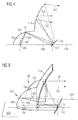
- the figure 5 illustrates schematically and in perspective a lighting device providing a lighting function of the code type or still low beam. It comprises a first lighting module 102 according to the invention and to the figure 2 combined with a second illumination module 126 of the imaging type direct.
- the second module 126 comprises a single reflector 128 of the parabolic type with a first focus where is placed a light source. The rays emitted by this light source are reflected by the reflective surface of the reflector 128 to form the illumination beam.
- This device is called direct imaging since the light images 132 produced by the light source are transmitted directly by simple reflection to the light beam.
- the light source 130 is disposed approximately in the same plane 136 as the light source 106 of the first module 102. This arrangement makes it possible to predict the light sources of the two modules on the same support (not shown), which has a definite advantage as to the simplicity of assembly especially in view of the cooling constraints inherent to light sources of the electroluminescence diode type.
- the second module 126 has the advantage of having fewer light losses and thus to be able to ensure a significant portion of the photometry of the lighting beam.
- the cut is provided by a worked form of the reflective surface of the reflector 128.
- the first module 102 provides additional lighting with, however, a cut substantially sharper than that of the second module. This combination of modules produces a cut-off lighting device having a particularly interesting performance and size.
Applications Claiming Priority (1)
| Application Number | Priority Date | Filing Date | Title |
|---|---|---|---|
| FR1056433A FR2966221B1 (fr) | 2010-08-04 | 2010-08-04 | Module d'eclairage a coupure avec reflecteur parabolique dispose sur un reflecteur elliptique |
Publications (2)
| Publication Number | Publication Date |
|---|---|
| EP2416061A2 true EP2416061A2 (de) | 2012-02-08 |
| EP2416061A3 EP2416061A3 (de) | 2012-08-08 |
Family
ID=43706774
Family Applications (1)
| Application Number | Title | Priority Date | Filing Date |
|---|---|---|---|
| EP11175169A Withdrawn EP2416061A3 (de) | 2010-08-04 | 2011-07-25 | Beleuchtungsmodul mit Abschaltfunktion mit einem Parabolreflektor, der auf einem elliptischen Reflektor angebracht ist |
Country Status (2)
| Country | Link |
|---|---|
| EP (1) | EP2416061A3 (de) |
| FR (1) | FR2966221B1 (de) |
Cited By (4)
| Publication number | Priority date | Publication date | Assignee | Title |
|---|---|---|---|---|
| CN108240603A (zh) * | 2016-12-23 | 2018-07-03 | 汽车照明罗伊特林根有限公司 | Led模块和用于机动车的具有多个这种led模块的照明装置 |
| CN109519865A (zh) * | 2019-01-03 | 2019-03-26 | 华域视觉科技(上海)有限公司 | 增加光型宽度的方法、辅助反射装置、led模组单元、车灯、汽车 |
| WO2022130595A1 (ja) * | 2020-12-17 | 2022-06-23 | 本田技研工業株式会社 | 車両用灯具 |
| EP4206524A4 (de) * | 2021-09-18 | 2024-01-03 | Hasco Vision Tech Co Ltd | Optisches reflexionssystem für fahrzeuglampenbeleuchtungsvorrichtung und fahrzeuglampenbeleuchtungsvorrichtung |
Families Citing this family (1)
| Publication number | Priority date | Publication date | Assignee | Title |
|---|---|---|---|---|
| FR3001027B1 (fr) | 2013-01-15 | 2015-03-20 | Valeo Vision | Module d'eclairage et procede de montage d'un tel module |
Citations (1)
| Publication number | Priority date | Publication date | Assignee | Title |
|---|---|---|---|---|
| FR2849158A1 (fr) | 2002-12-20 | 2004-06-25 | Valeo Vision | Module d'eclairage pour projecteur de vehicule |
Family Cites Families (3)
| Publication number | Priority date | Publication date | Assignee | Title |
|---|---|---|---|---|
| FR2678353A1 (fr) * | 1991-06-28 | 1992-12-31 | Valeo Vision | Projecteur a haute intensite lumineuse et a haute nettete de coupure. |
| FR2899668B1 (fr) * | 2006-04-06 | 2009-11-20 | Valeo Vision | Module d'eclairage pour projecteur lumineux de vehicule automobile, et projecteur comportant un tel module. |
| FR2917811B1 (fr) * | 2007-06-25 | 2009-10-02 | Valeo Vision Sa | Module d'eclairage pour projecteur de vehicule automobile |
-
2010
- 2010-08-04 FR FR1056433A patent/FR2966221B1/fr active Active
-
2011
- 2011-07-25 EP EP11175169A patent/EP2416061A3/de not_active Withdrawn
Patent Citations (1)
| Publication number | Priority date | Publication date | Assignee | Title |
|---|---|---|---|---|
| FR2849158A1 (fr) | 2002-12-20 | 2004-06-25 | Valeo Vision | Module d'eclairage pour projecteur de vehicule |
Cited By (6)
| Publication number | Priority date | Publication date | Assignee | Title |
|---|---|---|---|---|
| CN108240603A (zh) * | 2016-12-23 | 2018-07-03 | 汽车照明罗伊特林根有限公司 | Led模块和用于机动车的具有多个这种led模块的照明装置 |
| CN108240603B (zh) * | 2016-12-23 | 2022-12-13 | 汽车照明罗伊特林根有限公司 | Led模块和用于机动车的具有多个这种led模块的照明装置 |
| CN109519865A (zh) * | 2019-01-03 | 2019-03-26 | 华域视觉科技(上海)有限公司 | 增加光型宽度的方法、辅助反射装置、led模组单元、车灯、汽车 |
| CN109519865B (zh) * | 2019-01-03 | 2024-01-26 | 华域视觉科技(上海)有限公司 | 增加光型宽度的方法、装置、模组单元、车灯及汽车 |
| WO2022130595A1 (ja) * | 2020-12-17 | 2022-06-23 | 本田技研工業株式会社 | 車両用灯具 |
| EP4206524A4 (de) * | 2021-09-18 | 2024-01-03 | Hasco Vision Tech Co Ltd | Optisches reflexionssystem für fahrzeuglampenbeleuchtungsvorrichtung und fahrzeuglampenbeleuchtungsvorrichtung |
Also Published As
| Publication number | Publication date |
|---|---|
| EP2416061A3 (de) | 2012-08-08 |
| FR2966221B1 (fr) | 2015-09-18 |
| FR2966221A1 (fr) | 2012-04-20 |
Similar Documents
| Publication | Publication Date | Title |
|---|---|---|
| EP3124854B1 (de) | Beleuchtungssystem für kraftfahrzeugscheinwerfer | |
| EP2871406B1 (de) | Optisches Hauptelement, Beleuchtungsmodul und Scheinwerfer für Kraftfahrzeug | |
| EP3076070B1 (de) | Leuchtmodul für kraftfahrzeugscheinwerfer | |
| EP3708904B1 (de) | Leuchtvorrichtung, die die beleuchteten flächen von mindestens zwei kollektoren abbildet | |
| EP1528312B1 (de) | Beleuchtungsmodul für Kfz-Scheinwerfer | |
| EP3246620B1 (de) | Led-scheinwerfer für fahrzeuge mit diopter, der eine abschattung erzeugt | |
| EP3002504A2 (de) | Leuchtmodul zur beleuchtung und/oder signalisierung für kraftfahrzeug | |
| FR2995967B1 (fr) | Module d'eclairage, notamment pour vehicule automobile | |
| EP1500869A1 (de) | Elliptische Beleuchtungseinheit ohne Lichtblende zur Erzeugung eines Abblendlichtbündels und Scheinwerfer mit einer derartigen Belleuchtungseinheit | |
| FR3062461A1 (fr) | Module lumineux pivotable pour projecteur de vehicule | |
| FR3009366A1 (fr) | Projecteur et systeme d'eclairage notamment pour vehicule automobile | |
| EP2416061A2 (de) | Beleuchtungsmodul mit Abschaltfunktion mit einem Parabolreflektor, der auf einem elliptischen Reflektor angebracht ist | |
| EP4264120A1 (de) | Kraftfahrzeugscheinwerfer mit mehreren beleuchtungsmodulen auf einer geneigten gemeinsamen platte | |
| FR3038695A1 (fr) | Module lumineux pour l'eclairage et/ou la signalisation d'un vehicule automobile | |
| FR3006421A1 (fr) | Module d'eclairage pour projecteur de vehicule automobile, projecteur equipe de tels modules, et ensemble de projecteurs | |
| FR3126746A1 (fr) | Dispositif lumineux d’un véhicule automobile | |
| EP1944542B1 (de) | Scheinwerfer mit zwei Funktionen für Kraftfahrzeug | |
| EP2436968B1 (de) | Vorrichtung zur Ausstrahlung von Licht für einen Autoscheinwerfer | |
| EP3124856A1 (de) | Beleuchtungsvorrichtung für kraftfahrzeug | |
| WO2023031344A1 (fr) | Dispositif lumineux d'un véhicule automobile | |
| EP2366941A2 (de) | Beleuchtungsmodul mit zwei Scheinwerfern mit unterschiedlichen Brennpunktabständen | |
| FR3139881A1 (fr) | Module lumineux | |
| FR3054295A1 (fr) | Systeme lumineux pour dispositif d'eclairage et/ou de signalisation d'un vehicule automobile | |
| FR2911826A1 (fr) | Dispositif d'eclairage multifonction pour vehicule automobile. |
Legal Events
| Date | Code | Title | Description |
|---|---|---|---|
| AK | Designated contracting states |
Kind code of ref document: A2 Designated state(s): AL AT BE BG CH CY CZ DE DK EE ES FI FR GB GR HR HU IE IS IT LI LT LU LV MC MK MT NL NO PL PT RO RS SE SI SK SM TR |
|
| AX | Request for extension of the european patent |
Extension state: BA ME |
|
| PUAI | Public reference made under article 153(3) epc to a published international application that has entered the european phase |
Free format text: ORIGINAL CODE: 0009012 |
|
| PUAL | Search report despatched |
Free format text: ORIGINAL CODE: 0009013 |
|
| AK | Designated contracting states |
Kind code of ref document: A3 Designated state(s): AL AT BE BG CH CY CZ DE DK EE ES FI FR GB GR HR HU IE IS IT LI LT LU LV MC MK MT NL NO PL PT RO RS SE SI SK SM TR |
|
| AX | Request for extension of the european patent |
Extension state: BA ME |
|
| RIC1 | Information provided on ipc code assigned before grant |
Ipc: F21W 101/10 20060101ALN20120702BHEP Ipc: F21S 8/12 20060101AFI20120702BHEP Ipc: F21V 7/00 20060101ALI20120702BHEP Ipc: F21Y 101/02 20060101ALN20120702BHEP |
|
| 17P | Request for examination filed |
Effective date: 20130204 |
|
| GRAP | Despatch of communication of intention to grant a patent |
Free format text: ORIGINAL CODE: EPIDOSNIGR1 |
|
| RIC1 | Information provided on ipc code assigned before grant |
Ipc: F21S 41/36 20180101ALI20191106BHEP Ipc: F21S 41/14 20180101AFI20191106BHEP Ipc: F21S 41/43 20180101ALI20191106BHEP |
|
| INTG | Intention to grant announced |
Effective date: 20191203 |
|
| STAA | Information on the status of an ep patent application or granted ep patent |
Free format text: STATUS: THE APPLICATION IS DEEMED TO BE WITHDRAWN |
|
| 18D | Application deemed to be withdrawn |
Effective date: 20200603 |