EP2366941A2 - Beleuchtungsmodul mit zwei Scheinwerfern mit unterschiedlichen Brennpunktabständen - Google Patents
Beleuchtungsmodul mit zwei Scheinwerfern mit unterschiedlichen Brennpunktabständen Download PDFInfo
- Publication number
- EP2366941A2 EP2366941A2 EP11156344A EP11156344A EP2366941A2 EP 2366941 A2 EP2366941 A2 EP 2366941A2 EP 11156344 A EP11156344 A EP 11156344A EP 11156344 A EP11156344 A EP 11156344A EP 2366941 A2 EP2366941 A2 EP 2366941A2
- Authority
- EP
- European Patent Office
- Prior art keywords
- reflector
- light source
- lighting module
- reflectors
- lighting
- Prior art date
- Legal status (The legal status is an assumption and is not a legal conclusion. Google has not performed a legal analysis and makes no representation as to the accuracy of the status listed.)
- Withdrawn
Links
- 238000005286 illumination Methods 0.000 claims description 17
- 230000003287 optical effect Effects 0.000 description 6
- 230000006978 adaptation Effects 0.000 description 2
- 230000004075 alteration Effects 0.000 description 2
- 238000010276 construction Methods 0.000 description 2
- 230000000694 effects Effects 0.000 description 2
- 238000005516 engineering process Methods 0.000 description 2
- 230000002730 additional effect Effects 0.000 description 1
- 238000003776 cleavage reaction Methods 0.000 description 1
- 230000000295 complement effect Effects 0.000 description 1
- 238000012937 correction Methods 0.000 description 1
- 238000013461 design Methods 0.000 description 1
- 238000011161 development Methods 0.000 description 1
- 239000011521 glass Substances 0.000 description 1
- 238000005259 measurement Methods 0.000 description 1
- 238000000034 method Methods 0.000 description 1
- NJPPVKZQTLUDBO-UHFFFAOYSA-N novaluron Chemical compound C1=C(Cl)C(OC(F)(F)C(OC(F)(F)F)F)=CC=C1NC(=O)NC(=O)C1=C(F)C=CC=C1F NJPPVKZQTLUDBO-UHFFFAOYSA-N 0.000 description 1
- 238000005457 optimization Methods 0.000 description 1
- 230000007017 scission Effects 0.000 description 1
Images

Classifications
-
- F—MECHANICAL ENGINEERING; LIGHTING; HEATING; WEAPONS; BLASTING
- F21—LIGHTING
- F21S—NON-PORTABLE LIGHTING DEVICES; SYSTEMS THEREOF; VEHICLE LIGHTING DEVICES SPECIALLY ADAPTED FOR VEHICLE EXTERIORS
- F21S41/00—Illuminating devices specially adapted for vehicle exteriors, e.g. headlamps
- F21S41/60—Illuminating devices specially adapted for vehicle exteriors, e.g. headlamps characterised by a variable light distribution
- F21S41/65—Illuminating devices specially adapted for vehicle exteriors, e.g. headlamps characterised by a variable light distribution by acting on light sources
- F21S41/663—Illuminating devices specially adapted for vehicle exteriors, e.g. headlamps characterised by a variable light distribution by acting on light sources by switching light sources
-
- F—MECHANICAL ENGINEERING; LIGHTING; HEATING; WEAPONS; BLASTING
- F21—LIGHTING
- F21S—NON-PORTABLE LIGHTING DEVICES; SYSTEMS THEREOF; VEHICLE LIGHTING DEVICES SPECIALLY ADAPTED FOR VEHICLE EXTERIORS
- F21S41/00—Illuminating devices specially adapted for vehicle exteriors, e.g. headlamps
- F21S41/30—Illuminating devices specially adapted for vehicle exteriors, e.g. headlamps characterised by reflectors
- F21S41/32—Optical layout thereof
- F21S41/323—Optical layout thereof the reflector having two perpendicular cross sections having regular geometrical curves of a distinct nature
-
- F—MECHANICAL ENGINEERING; LIGHTING; HEATING; WEAPONS; BLASTING
- F21—LIGHTING
- F21S—NON-PORTABLE LIGHTING DEVICES; SYSTEMS THEREOF; VEHICLE LIGHTING DEVICES SPECIALLY ADAPTED FOR VEHICLE EXTERIORS
- F21S41/00—Illuminating devices specially adapted for vehicle exteriors, e.g. headlamps
- F21S41/30—Illuminating devices specially adapted for vehicle exteriors, e.g. headlamps characterised by reflectors
- F21S41/32—Optical layout thereof
- F21S41/36—Combinations of two or more separate reflectors
-
- F—MECHANICAL ENGINEERING; LIGHTING; HEATING; WEAPONS; BLASTING
- F21—LIGHTING
- F21S—NON-PORTABLE LIGHTING DEVICES; SYSTEMS THEREOF; VEHICLE LIGHTING DEVICES SPECIALLY ADAPTED FOR VEHICLE EXTERIORS
- F21S41/00—Illuminating devices specially adapted for vehicle exteriors, e.g. headlamps
- F21S41/60—Illuminating devices specially adapted for vehicle exteriors, e.g. headlamps characterised by a variable light distribution
-
- F—MECHANICAL ENGINEERING; LIGHTING; HEATING; WEAPONS; BLASTING
- F21—LIGHTING
- F21S—NON-PORTABLE LIGHTING DEVICES; SYSTEMS THEREOF; VEHICLE LIGHTING DEVICES SPECIALLY ADAPTED FOR VEHICLE EXTERIORS
- F21S41/00—Illuminating devices specially adapted for vehicle exteriors, e.g. headlamps
- F21S41/30—Illuminating devices specially adapted for vehicle exteriors, e.g. headlamps characterised by reflectors
- F21S41/32—Optical layout thereof
- F21S41/321—Optical layout thereof the reflector being a surface of revolution or a planar surface, e.g. truncated
-
- F—MECHANICAL ENGINEERING; LIGHTING; HEATING; WEAPONS; BLASTING
- F21—LIGHTING
- F21Y—INDEXING SCHEME ASSOCIATED WITH SUBCLASSES F21K, F21L, F21S and F21V, RELATING TO THE FORM OR THE KIND OF THE LIGHT SOURCES OR OF THE COLOUR OF THE LIGHT EMITTED
- F21Y2115/00—Light-generating elements of semiconductor light sources
- F21Y2115/10—Light-emitting diodes [LED]
Definitions
- the invention relates to a particular lighting module for a motor vehicle, more particularly a lighting module with two reflective surfaces for a light source. More particularly still, the light source is capable of directionally illuminating in a half-space as typically a light-emitting diode.
- the patent document AT 500 750 A4 relates to this problem and tries to solve it by proposing a projector that can provide the lighting functions of the type "fog", "road” and / or "code”.
- the projector includes a main reflector collecting a main beam of rays emitted from a light-emitting diode-type light source and reflecting it into a lighting beam.
- the main direction of emission of the diode is inclined at about 60 ° with respect to the direction of illumination, and this rearward so that the main reflector can best exploit the rays emitted by the source.
- the emission of light rays by a diode is indeed quite direct in that the maximum power is generally in a sector of 60 ° centered on the main direction of emission.
- a second reflector is disposed adjacent to and in front of the main reflector so as to recover a portion of the lower power rays, typically outside the maximum power sector of the reflector. 60 °, and reflect in a direction perpendicular to the direction of illumination to a third plane reflector that will then reflect them in the direction of illumination. These secondary rays will thus be added to the main lighting rays, thereby increasing the energy efficiency of the projector while maintaining its very small footprint.
- the projector proposed by this patent document is interesting but has limitations as to the increase in yield generated due to the low relative power of the beam recovered by the second reflector.
- the proposed projector also has limitations as to the quality of the projected image due to the focal length of the main reflector which remains rather small due to space constraints.
- the object of the invention is to propose a lighting module that overcomes at least one of the disadvantages mentioned above. More particularly, the invention aims to provide a lighting module optimizing the energy efficiency, the size and the image quality of the lighting beam.
- the invention consists of a lighting module, in particular for a motor vehicle headlamp, comprising: a light source support capable of emitting light rays in a half-space delimited by a plane passing through the support; a first reflector with a reflective surface and a first focal point at a first focal distance, the light source being intended to be positioned at this first focus, said first reflector being able to reflect the light rays emitted by the light source and meeting it in a first lighting beam; a second reflector with a reflective surface and a second focus at a second focal length less than the first focal length, said second focus corresponding to said first focus, said second reflector being able to reflect the light rays emitted by the light source and meeting it in a second lighting beam; the second reflector comprising an edge defining its reflective surface and the first reflector being configured to collect the rays emitted by the light source passing beyond said edge.
- This construction makes it possible to reduce the surface of the main reflector of a lighting module for the sake of compactness and to compensate for this reduction in area and therefore in lighting power by the addition of a small focal length reflector. proximity of the light source, between it and the main reflector, the small focal reflector can collect and reflect a large part of the lost rays.
- the second reflector is disposed at least partially between the first reflector and the light source.
- the edge of the reflective surface of the second reflector constitutes the boundary between the rays emitted by the light source which are collected by the first reflector and those which are collected by the second reflector. This measurement makes it possible to optimize each reflector so that no ray is lost between the two surfaces of the reflectors.
- the ratio between the first and second focal lengths has a value of between 5 and 10, the first focal length being preferably between 18 and 25 mm.
- the first and second reflectors are configured and arranged relative to each other so that the portion of the beam of rays emitted by the light source which is collected by the one of the reflectors is included in the part of the ray beam emitted by the light source which is collected by the other of the reflectors, and in a direction transverse to the illumination direction.
- the second reflector comprises an elongate surface, preferably of approximately constant width, whose main direction is directed in a plane passing through the light source, perpendicular to the plane delimiting the half-space of said source and oriented according to the second illumination beam.
- this elongated surface is a complex surface.
- a complex surface is a surface capable of forming a light beam, for example of the code type, without using a cup obscuring part of the surface and without using striated glass.
- a complex surface may be formed of an assembly of elementary sectors, each sector connecting to the immediately adjacent sector along generally vertical lines. Each sector is advantageously generated by a horizontal generator from which a set of vertical curves upwards then downwards.
- the horizontal generatrix is for example convex and its profile determines the horizontal distribution of the beam generated by the sector.
- the generatrices of the sectors are chosen so that the rays coming from the source are reflected by the surface while being directed downwards to form the cut, for example the cleavage of the code.
- Vertical curves are, for example, parabolic arcs.
- the foci of each parable upward are generally distinct from the foci of the parables going downward.
- the arcs may differ from a parabola and may be coplanar curves that can be defined by a set of foci (at each height, a different focus is associated).
- the first reflector comprises a surface distributed on either side of a plane passing through the light source and perpendicular to the plane delimiting the half-space of said source, this surface surrounding the second reflector in a plane parallel to the plane delimiting the half-space of said source.
- This surface is preferably essentially a complex surface.
- this complex surface is double and preferably symmetrical with respect to a plane passing through the light source and perpendicular to the plane delimiting the half-space of said source. Note that it can also be non-symmetrical.
- the surface of the first reflector has a profile such that it generates a beam with cutoff.
- the first and second reflectors are designed and arranged so that the rays reflected by the first reflector pass mainly the second reflector, the rear face of the surface of the second reflector being preferentially free of support on the side of the light source so as to promote the passage of said rays reflected by the first reflector.
- the module is a lighting module of the "code” or "fog” type.
- the first and second reflectors are configured and arranged relative to each other so that the beam of rays emitted by the light source which is collected by the one reflectors is surrounded by the beam of rays emitted by the light source which is collected by the other of the reflectors.
- the second reflector comprises a surface with an opening in front of the light source, said surface of the second reflector forming the second lighting beam, the first reflector comprising a surface arranged so as to collecting the rays emitted by the light source passing through said orifice and forming the first light beam.
- the surface of the second reflector and / or the surface of the first reflector are complex surfaces.
- the surface of the second reflector may be symmetrical or not.
- the first illumination beam is essentially parallel to the second illumination beam and, preferably, the surface of the second reflector is cut at the front part so as to provide a passage for the first lighting beam.
- the first lighting beam is essentially parallel to the second lighting beam and is added thereto.
- the module is a lighting module of the "road" type.
- the invention also consists of a motor vehicle headlamp with a lighting direction comprising a first module and a second module as described above, the second module being placed under or next to the first module with respect to the direction. lighting.
- the invention also consists of a vehicle equipped with at least one module and / or projector as described above.
- Embodiments of the invention are illustrated in the figures and described hereinafter with respect to a mounting position of the device in a vehicle as a projector.
- This type of application although preponderant is not limiting so that the terms used such as “horizontal”, “vertical”, “high”, “low”, “superior”, “lower”
- forward, “backward” to describe the positions of the different elements are not absolute but rather to be interpreted in a relative manner describing the positions of the elements with respect to their arrangement in the figures.
- the described lighting devices could be mounted in other positions and / or for other applications.
- the relative positions of the various optical elements such as the light sources and the reflectors expressed for the simplicity of understanding by alignment of the optical axes and / or correspondence of the respective foci are not to be interpreted in an exact manner insofar as light variations are conceivable or even desirable in order, among other things, to correct the non-perfect nature and certain optical aberrations of the optical elements or to obtain certain additional effects such as, for example, a cut-off effect.
- the reflectors of a projector according to the invention are illustrated in their mounting positions to the figure 1 .
- the projector comprises a first upper module 2 adapted to provide a cut-off lighting function of the "code” type and a second lower module 4 capable of providing a "road” type uninterrupted lighting function.
- the upper module 2 comprises two reflectors, a first reflector 6 with a reflection surface forming an enclosure of generally complex section and a second reflector 8 of elongate shape with a complex surface, the second reflector being disposed inside the enclosure formed by the first reflector 6.
- the surface of the first reflector 6 is a complex surface of parabolic type, namely a complex surface obtained from arches of parabola.
- the surface of the second reflector 8 is also a complex surface of parabolic type.
- the location of the light source of the module cooperating with these two reflectors 6 and 8 is illustrated by a point 10 referenced. Coordinate axes x, y and z y are represented for the sake of clarity of presentation which follows.
- the second reflector 8 has a tongue shape or track oriented in the direction of projection x extending from the front of the module to near the light source 10.
- This reflector has a side edge 20 and a free edge 21 to its rear end, approximately rounded to a precise geometry so as to collect a selected beam of light rays emitted by the light source 10, the other rays meeting the surface of the first reflector.
- the rays reflected by the two reflectors add up and form the lighting beam.
- the second lower module 4 also comprises two reflectors: a first reflector 14 corresponding to a section or piece of complex surface and a second reflector 12 in a half-space with a cutout 22 which will be explained later.
- the light source of the second module is represented at figure 2 which is a plan view of the projector from the figure 1 by a point referenced 16. It is observed in this figure that the cutout 22 of the second reflector 12 corresponds to a segment of a circle which itself corresponds to the intersection with the projection of the edges of the first reflector 14 towards the front according to the projection axis x.
- An orifice 18 is provided in the center of the surface of the second reflector 12 so as to pass a beam of light rays to the first reflector 14.
- the size of the projector which corresponds essentially to that of the reflectors assembled in the operating position, is illustrated by the dimensions of width l and height h at the figure 2 . Given the reflective surfaces and their focal lengths as discussed below, the width l is of the order of 120 mm and the height h of the order of 140 mm. These values are purely illustrative for the purpose of illustrating the compactness of the module.
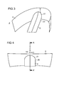
- the figure 3 is a perspective view of the two reflectors 6 and 8 illustrating their shapes and relative positions.
- the reflector 8 has an elongated shape, of generally constant width, at least over a major part of its length. It is directed according to the lighting direction and has a profile in a vertical median plane. It corresponds in fact to a section of complex surface symmetrical in revolution with respect to the axis x. Its rear end has an approximately rounded edge 21 near the light source. This edge 21 may, however, have straight sections or at least irregularities in its profile depending on the specific design that will be chosen.
- the figure 4 is a plan view of the two reflectors of the figure 3 .
- the figure 5 is an elevational view of the two reflectors of the figure 3 .
- the first reflector 6 is symmetrical with respect to the vertical median plane (xz plane). It presents a profile of revolution with however a particularity at the level of the zone near the median axis x. In fact, the profile presents, with respect to the x-axis, a point of inflection which bears witness to an irregularity. This irregularity is due to the presence of the second reflector 8 which is an obstacle that the rays collected and reflected by the first reflector 6 must bypass. This is the reason why the surface of the reflector 6 has larger radius of curvature in this area relative to the remaining profile of the reflector. The surface of this zone is quite complex considering the complex shape of the obstacle formed by the reflector 8. Indeed, as is well illustrated in FIG.
- the second reflector 8 is held by a pedestal at its front while its rear portion is free. This means that the rays reflected by the area of the first reflector 6 which is located opposite the reflector 8 must be reflected so as to avoid the reflector. They are actually reflected so as to form an angle with the x-axis and to avoid the second reflector 8 to then meet the front part of the first reflector 6 and be reflected again in a direction substantially parallel to the x-axis.
- the development of the surface of the first reflector 6 is the result of a calculation made by computer and that the skilled person can easily achieve on the basis of the aforementioned constraints.
- the main and remaining surface of the first reflector 6 corresponds exactly to a parabolic surface section but to a complex surface.
- the lighting function of the module in question is of the cutoff type, this cutoff being achieved by an adaptation of the main reflecting surface.
- Light source 10 of the light emitting diode type is arranged to emit its rays in a half-space directed downwards and delimited by the x-y plane.
- the image of the light source which, in the case of a perfect parabolic reflector, would be generally circular, is in fact "flattened” by adaptation of the surface of the reflector.
- the parabolic profile of the reflecting surface is modified so as to reflect the majority of the rays under a line corresponding to the cut. This technique of modifying the parabolic surface to obtain a cut is known to those skilled in the art.
- the two reflectors 6 and 8 are dimensioned to complement one another, namely so that the rays emitted by the light source 10 which pass near the edge 20 of the second reflector 8 are collected and reflected by the first reflector 6 It is in particular the role of the free edge 21 of the rear end of the reflector 8 which corresponds essentially to the profile described by a generator starting from the light source and running through the lower edge of the reflecting surface of the first reflector 6.
- the figure 6 is a sectional view of the two reflectors along the axis AA 'of the figure, illustrating the focal lengths.
- the surface of the second reflector 8 is a complex surface.
- the representation in median section of the second reflector 8 illustrates a profile obtained from a parabola arc. An extension of this profile is illustrated by a dashed line and the distance between the focus 10 of this parabola and the point of inflection or apex of the parabola is the focal length f 2 .
- the focus of the surface corresponds to the location of the light source 10. This focal length f 2 corresponds to the focus of the complex surface of the second reflector 8.
- the profile of the surface of the first reflector 6 is also extended by a dashed line in such a way as to be able to reveal the point of inflection or vertex of a parabola arc from which the complex surface is constructed.
- the focal length of the parabola in question corresponds to the distance f 1 between the focus 10 and the top of the parabola.
- This focal length f 1 corresponds to the focus of the complex surface of the first reflector 6.
- this dotted line representation of the parabolic section of the reflector 6 is a simplified view taking into account the particularities and corrections that are made to the surface. in order essentially to avoid the reflector 8 and to ensure a cut of the reflected beam and as discussed above.
- the focal length f 2 of the second reflector 8 is typically of the order of a few millimeters, preferably between 1.5 and 6 mm, more preferably between 2 and 5 mm. .
- the focal length f 1 of the first reflector 6 typically varies between 15 and 30 mm, more preferably between 18 and 25 mm.
- the first reflector 6 collects approximately 60% of the rays emitted by the light source and hence produces most of the illumination beam.
- the second reflector 8 collects about 65% of the rest of the rays emitted by the light source. It produces a diffuse beam of lower power, enriching the main beam.
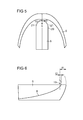
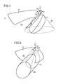
- the figure 7 is a perspective view of module 4 in question.
- Light source 16 of the light emitting diode type is arranged so as to emit its rays in a half-space directed downwards and delimited by the xy plane.
- the first reflector 14 is a symmetrical complex surface section in revolution about the x axis. This section corresponds to the intersection of the projection cone 24 with the surface in question (which is represented only by the section). The surface section of the first reflector 14 will reflect the conical beam 24 into a beam parallel to the x axis with a generally cylindrical envelope 26 as illustrated in FIG. figure 8 .
- the second reflector is a reflector in a half-space disposed substantially in the half-light space of the light source 16.
- the latter is symbolically represented by the point 16 from which the x, y and z coordinate axes.
- the surface of the reflector 12 has an opening 18 in line with the light source 16. This opening corresponds to the intersection of a cylinder parallel to the x-axis with the surface of the reflector. It follows from this opening 18 that a beam of rays emitted by the light source passes the reflector 12 and meets the first reflector 14 disposed lower.
- the beam of rays passing through the second reflector 12 is cone-shaped 24.
- the projection cone 24 typically has an angle of the order of 60 ° centered on the main axis of emission of the light source (z axis), which corresponds to about 80% of the emission power of a light-emitting diode.
- the cutout 22 of the second reflector 12 corresponds to the intersection of the surface of the reflector with the cylindrical envelope 26 of the beam reflected by the first reflector 14.
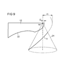
- the figure 9 is a sectional view along a vertical median plane xz of the two reflectors of Figures 7 and 8 , illustrating the respective focal lengths.
- the focal length f 2 of the second reflector 12 corresponds to the focal length of the complex surface of the second reflector 12.
- figure 9 at the focal length f 2 is represented by the distance between the focus 16 and the apex of a parabola arc from which builds a sector of the complex surface of the second reflector 12.
- the focus of the complex surface corresponds to the location of the light source 16.
- the profile of the complex surface of the first reflector 14 is obtained from a parabola arc. This profile is extended by a dotted line to the top of the parable in question.
- the focal length f 1 of the first reflector 14 corresponds to the distance between the focus 16 and the top of the dish.
- the focus of the surface of the first reflector 14 corresponds to the location of the light source 16.
- the focal length f 2 of the second reflector 8 is typically of the order of a few millimeters, preferably between 1.5 and 6 mm, more preferably between 2 and 5 mm. .
- the focal length f 1 of the first reflector 6 typically varies between 15 and 30 mm, more preferably between 18 and 25 mm.
- the first reflector 14 collects approximately 60% of the rays emitted by the light source and hence produces most of the illumination beam.
- the second reflector 12 collects about 65% of the rest of the rays emitted by the light source. It produces a diffuse beam of lower power, enriching the main beam.
- the first reflector is sized to have a sufficient focal length to ensure a quality projection of the image of the light source.
- the surface of the first reflector has been reduced by keeping only a piece of a symmetrical complex surface in revolution in a half-space because of space constraints. It can also be non-symmetrical.
- the piece of surface guarded was chosen to collect a major portion of the lighting power of the source, typically of the order of 60%.
- the choice of a substantially smaller focal distance for the second reflector makes it possible to arrange it between the first reflector and the light source so as to recover a large portion of the rays that the first reflector can not collect, without increasing the size of the module.
- the second reflector due to its smaller focal length, generates a diffuse beam that enriches the main beam, the image of the latter being controlled by means of the first reflector of greater focal length.
- the two modules described in connection with the figures have very particular reflector geometries, making it possible to implement the principle described above. Other geometries are of course conceivable depending on various parameters such as that of the desired lighting function, the size and number of light sources, etc.
- the concepts of "first reflector” and "second reflector” have been used for purposes of clarity of presentation.
- the principle described above can be realized with more reflectors. It is indeed quite possible to provide, for example, at least one of the first and second reflectors consisting of two separate reflectors or to provide three reflectors with three different focal lengths, or more.
- the projector described in connection with the Figures 1 and 2 comprises two modules, a first upper module and a second lower module.
- first module (upper) and “second module (lower)” were used for the end of the presentation.
- second has been used knowingly because the exemplary embodiment comprises exactly two modules. It should be noted, however, that the described projector can be realized with a single module or more than two modules.
Landscapes
- Engineering & Computer Science (AREA)
- General Engineering & Computer Science (AREA)
- Physics & Mathematics (AREA)
- Geometry (AREA)
- Non-Portable Lighting Devices Or Systems Thereof (AREA)
- Led Device Packages (AREA)
Applications Claiming Priority (1)
| Application Number | Priority Date | Filing Date | Title |
|---|---|---|---|
| FR1051606A FR2957134B1 (fr) | 2010-03-05 | 2010-03-05 | Module d'eclairage avec deux reflecteurs de distances focales differentes |
Publications (2)
| Publication Number | Publication Date |
|---|---|
| EP2366941A2 true EP2366941A2 (de) | 2011-09-21 |
| EP2366941A3 EP2366941A3 (de) | 2013-01-30 |
Family
ID=42674622
Family Applications (1)
| Application Number | Title | Priority Date | Filing Date |
|---|---|---|---|
| EP11156344A Withdrawn EP2366941A3 (de) | 2010-03-05 | 2011-03-01 | Beleuchtungsmodul mit zwei Scheinwerfern mit unterschiedlichen Brennpunktabständen |
Country Status (2)
| Country | Link |
|---|---|
| EP (1) | EP2366941A3 (de) |
| FR (1) | FR2957134B1 (de) |
Cited By (2)
| Publication number | Priority date | Publication date | Assignee | Title |
|---|---|---|---|---|
| US9097400B2 (en) | 2011-10-31 | 2015-08-04 | Sl Corporation | Automotive headlamp |
| EP2587123A3 (de) * | 2011-10-31 | 2015-11-04 | SL Corporation | Autoscheinwerfer |
Citations (2)
| Publication number | Priority date | Publication date | Assignee | Title |
|---|---|---|---|---|
| EP0373065A1 (de) | 1988-12-07 | 1990-06-13 | Valeo Vision | Scheinwerfer für ein Kraftfahrzeug, versehen mit einem komplexen Spiegel mit geänderten Zwischenzonen |
| AT500750A4 (de) | 2003-06-06 | 2006-03-15 | Zizala Lichtsysteme Gmbh | Fahrzeugscheinwerfer |
Family Cites Families (3)
| Publication number | Priority date | Publication date | Assignee | Title |
|---|---|---|---|---|
| FR2579721B1 (fr) * | 1985-03-26 | 1988-10-14 | Cibie Projecteurs | Ensemble d'eclairage de route a deux projecteurs pour vehicule automobile |
| JP2004259541A (ja) * | 2003-02-25 | 2004-09-16 | Cateye Co Ltd | 照明器具 |
| DE10359185B4 (de) * | 2003-12-17 | 2012-05-31 | Hella Kgaa Hueck & Co. | Leuchte für Fahrzeuge |
-
2010
- 2010-03-05 FR FR1051606A patent/FR2957134B1/fr not_active Expired - Fee Related
-
2011
- 2011-03-01 EP EP11156344A patent/EP2366941A3/de not_active Withdrawn
Patent Citations (2)
| Publication number | Priority date | Publication date | Assignee | Title |
|---|---|---|---|---|
| EP0373065A1 (de) | 1988-12-07 | 1990-06-13 | Valeo Vision | Scheinwerfer für ein Kraftfahrzeug, versehen mit einem komplexen Spiegel mit geänderten Zwischenzonen |
| AT500750A4 (de) | 2003-06-06 | 2006-03-15 | Zizala Lichtsysteme Gmbh | Fahrzeugscheinwerfer |
Cited By (2)
| Publication number | Priority date | Publication date | Assignee | Title |
|---|---|---|---|---|
| US9097400B2 (en) | 2011-10-31 | 2015-08-04 | Sl Corporation | Automotive headlamp |
| EP2587123A3 (de) * | 2011-10-31 | 2015-11-04 | SL Corporation | Autoscheinwerfer |
Also Published As
| Publication number | Publication date |
|---|---|
| FR2957134B1 (fr) | 2015-08-21 |
| EP2366941A3 (de) | 2013-01-30 |
| FR2957134A1 (fr) | 2011-09-09 |
Similar Documents
| Publication | Publication Date | Title |
|---|---|---|
| EP3708904B1 (de) | Leuchtvorrichtung, die die beleuchteten flächen von mindestens zwei kollektoren abbildet | |
| EP1686310B1 (de) | Kfz-Scheinwerfer mit im wesentlichen vertikaler Ausdehnung | |
| EP2199664B1 (de) | Beleuchtungsvorrichtung für Fahrzeugscheinwerfer, der mehrere Beleuchtungsfunktionen oder eine veränderbare Funktion mit einer einzigen Lichtquelle ermöglicht | |
| FR3010772A1 (fr) | Dispositif d'emission de lumiere pour projecteur de vehicule automobile | |
| FR2944578A1 (fr) | Module et dispositif d'eclairage pour vehicule avec fonction route amelioree | |
| EP1684004B1 (de) | Fahrzeugscheinwerfer mit zwei Beleuchtungsverteilungen | |
| EP3246620A1 (de) | Led-scheinwerfer für fahrzeuge mit diopter, der eine abschattung erzeugt | |
| FR3118120A1 (fr) | Projecteur automobile avec plusieurs modules d’éclairage sur une platine commune inclinée. | |
| WO2022129426A1 (fr) | Module d'éclairage pour véhicule automobile | |
| FR3038696A1 (fr) | Module lumineux pour l'eclairage et/ou la signalisation d'un vehicule automobile | |
| EP2019258A1 (de) | Optisches Modul mit Lichtquelle für Scheinwerfer eines Kraftfahrzeugs | |
| EP2597360A1 (de) | Lichtemittierende Einrichtung für Kraftfahrzeugscheinwerfer | |
| EP1491816B1 (de) | Kfz-Scheinwerfer mit einem Spiegel und einem optischen Umlenkelement | |
| EP1600689B1 (de) | Multifunktions-Scheinwerfer für Kraftfahrzeuge | |
| EP1944542B1 (de) | Scheinwerfer mit zwei Funktionen für Kraftfahrzeug | |
| EP2416061A2 (de) | Beleuchtungsmodul mit Abschaltfunktion mit einem Parabolreflektor, der auf einem elliptischen Reflektor angebracht ist | |
| FR3048065A1 (fr) | Module et dispositif d'eclairage a encombrement reduit pour vehicule automobile | |
| FR2965326A1 (fr) | Dispositif d'emission de lumiere pour projecteur d'un vehicule automobile | |
| EP2366941A2 (de) | Beleuchtungsmodul mit zwei Scheinwerfern mit unterschiedlichen Brennpunktabständen | |
| EP2101105B1 (de) | Beleuchtungsvorrichtung für Kraftfahrzeug | |
| EP1832805B1 (de) | Optisches Modul für Autoscheinwerfer, ausgestattet mit einem optischen Ablenkelement | |
| FR2861832A1 (fr) | Projecteur pour vehicule automobile comportant une source lumineuse formee par une lampe a decharge | |
| EP1348594A1 (de) | Kfz-Scheinwerfer mit einem schwenkbaren, elliptischen Reflektor und einer fixen Linse zur Erzeugung eines Kurvenlichtbündels | |
| EP1731829B1 (de) | Kfz-Scheinwerfer | |
| WO2024133404A1 (fr) | Dispositif lumineux comprenant une pluralité de modules |
Legal Events
| Date | Code | Title | Description |
|---|---|---|---|
| PUAI | Public reference made under article 153(3) epc to a published international application that has entered the european phase |
Free format text: ORIGINAL CODE: 0009012 |
|
| AK | Designated contracting states |
Kind code of ref document: A2 Designated state(s): AL AT BE BG CH CY CZ DE DK EE ES FI FR GB GR HR HU IE IS IT LI LT LU LV MC MK MT NL NO PL PT RO RS SE SI SK SM TR |
|
| AX | Request for extension of the european patent |
Extension state: BA ME |
|
| PUAL | Search report despatched |
Free format text: ORIGINAL CODE: 0009013 |
|
| AK | Designated contracting states |
Kind code of ref document: A3 Designated state(s): AL AT BE BG CH CY CZ DE DK EE ES FI FR GB GR HR HU IE IS IT LI LT LU LV MC MK MT NL NO PL PT RO RS SE SI SK SM TR |
|
| AX | Request for extension of the european patent |
Extension state: BA ME |
|
| RIC1 | Information provided on ipc code assigned before grant |
Ipc: F21V 7/00 20060101AFI20121221BHEP Ipc: F21Y 101/02 20060101ALN20121221BHEP Ipc: F21S 8/12 20060101ALI20121221BHEP Ipc: F21W 101/10 20060101ALN20121221BHEP |
|
| 17P | Request for examination filed |
Effective date: 20130716 |
|
| RBV | Designated contracting states (corrected) |
Designated state(s): AL AT BE BG CH CY CZ DE DK EE ES FI FR GB GR HR HU IE IS IT LI LT LU LV MC MK MT NL NO PL PT RO RS SE SI SK SM TR |
|
| 17Q | First examination report despatched |
Effective date: 20200107 |
|
| STAA | Information on the status of an ep patent application or granted ep patent |
Free format text: STATUS: THE APPLICATION HAS BEEN WITHDRAWN |
|
| 18W | Application withdrawn |
Effective date: 20200717 |