EP2196258B1 - Reaktor - Google Patents
Reaktor Download PDFInfo
- Publication number
- EP2196258B1 EP2196258B1 EP09252638.3A EP09252638A EP2196258B1 EP 2196258 B1 EP2196258 B1 EP 2196258B1 EP 09252638 A EP09252638 A EP 09252638A EP 2196258 B1 EP2196258 B1 EP 2196258B1
- Authority
- EP
- European Patent Office
- Prior art keywords
- reformer
- liquid
- reactor
- face
- reforming
- Prior art date
- Legal status (The legal status is an assumption and is not a legal conclusion. Google has not performed a legal analysis and makes no representation as to the accuracy of the status listed.)
- Not-in-force
Links
Images


Classifications
-
- B—PERFORMING OPERATIONS; TRANSPORTING
- B01—PHYSICAL OR CHEMICAL PROCESSES OR APPARATUS IN GENERAL
- B01J—CHEMICAL OR PHYSICAL PROCESSES, e.g. CATALYSIS OR COLLOID CHEMISTRY; THEIR RELEVANT APPARATUS
- B01J19/00—Chemical, physical or physico-chemical processes in general; Their relevant apparatus
- B01J19/24—Stationary reactors without moving elements inside
- B01J19/248—Reactors comprising multiple separated flow channels
- B01J19/2485—Monolithic reactors
-
- B—PERFORMING OPERATIONS; TRANSPORTING
- B01—PHYSICAL OR CHEMICAL PROCESSES OR APPARATUS IN GENERAL
- B01J—CHEMICAL OR PHYSICAL PROCESSES, e.g. CATALYSIS OR COLLOID CHEMISTRY; THEIR RELEVANT APPARATUS
- B01J4/00—Feed or outlet devices; Feed or outlet control devices
- B01J4/001—Feed or outlet devices as such, e.g. feeding tubes
- B01J4/002—Nozzle-type elements
-
- C—CHEMISTRY; METALLURGY
- C01—INORGANIC CHEMISTRY
- C01B—NON-METALLIC ELEMENTS; COMPOUNDS THEREOF; METALLOIDS OR COMPOUNDS THEREOF NOT COVERED BY SUBCLASS C01C
- C01B3/00—Hydrogen; Gaseous mixtures containing hydrogen; Separation of hydrogen from mixtures containing it; Purification of hydrogen; Reversible storage of hydrogen
- C01B3/02—Production of hydrogen; Production of gaseous mixtures containing hydrogen
- C01B3/32—Production of hydrogen; Production of gaseous mixtures containing hydrogen by reaction of gaseous or liquid organic compounds with gasifying agents, e.g. water, carbon dioxide or air
- C01B3/34—Production of hydrogen; Production of gaseous mixtures containing hydrogen by reaction of gaseous or liquid organic compounds with gasifying agents, e.g. water, carbon dioxide or air by reaction of hydrocarbons with gasifying agents
- C01B3/342—Production of hydrogen; Production of gaseous mixtures containing hydrogen by reaction of gaseous or liquid organic compounds with gasifying agents, e.g. water, carbon dioxide or air by reaction of hydrocarbons with gasifying agents with the aid of electrical means, electromagnetic or mechanical vibrations, or particle radiations
-
- C—CHEMISTRY; METALLURGY
- C01—INORGANIC CHEMISTRY
- C01B—NON-METALLIC ELEMENTS; COMPOUNDS THEREOF; METALLOIDS OR COMPOUNDS THEREOF NOT COVERED BY SUBCLASS C01C
- C01B3/00—Hydrogen; Gaseous mixtures containing hydrogen; Separation of hydrogen from mixtures containing it; Purification of hydrogen; Reversible storage of hydrogen
- C01B3/02—Production of hydrogen; Production of gaseous mixtures containing hydrogen
- C01B3/32—Production of hydrogen; Production of gaseous mixtures containing hydrogen by reaction of gaseous or liquid organic compounds with gasifying agents, e.g. water, carbon dioxide or air
- C01B3/34—Production of hydrogen; Production of gaseous mixtures containing hydrogen by reaction of gaseous or liquid organic compounds with gasifying agents, e.g. water, carbon dioxide or air by reaction of hydrocarbons with gasifying agents
- C01B3/38—Production of hydrogen; Production of gaseous mixtures containing hydrogen by reaction of gaseous or liquid organic compounds with gasifying agents, e.g. water, carbon dioxide or air by reaction of hydrocarbons with gasifying agents using catalysts
-
- C—CHEMISTRY; METALLURGY
- C01—INORGANIC CHEMISTRY
- C01B—NON-METALLIC ELEMENTS; COMPOUNDS THEREOF; METALLOIDS OR COMPOUNDS THEREOF NOT COVERED BY SUBCLASS C01C
- C01B3/00—Hydrogen; Gaseous mixtures containing hydrogen; Separation of hydrogen from mixtures containing it; Purification of hydrogen; Reversible storage of hydrogen
- C01B3/02—Production of hydrogen; Production of gaseous mixtures containing hydrogen
- C01B3/32—Production of hydrogen; Production of gaseous mixtures containing hydrogen by reaction of gaseous or liquid organic compounds with gasifying agents, e.g. water, carbon dioxide or air
- C01B3/34—Production of hydrogen; Production of gaseous mixtures containing hydrogen by reaction of gaseous or liquid organic compounds with gasifying agents, e.g. water, carbon dioxide or air by reaction of hydrocarbons with gasifying agents
- C01B3/38—Production of hydrogen; Production of gaseous mixtures containing hydrogen by reaction of gaseous or liquid organic compounds with gasifying agents, e.g. water, carbon dioxide or air by reaction of hydrocarbons with gasifying agents using catalysts
- C01B3/386—Catalytic partial combustion
-
- B—PERFORMING OPERATIONS; TRANSPORTING
- B01—PHYSICAL OR CHEMICAL PROCESSES OR APPARATUS IN GENERAL
- B01J—CHEMICAL OR PHYSICAL PROCESSES, e.g. CATALYSIS OR COLLOID CHEMISTRY; THEIR RELEVANT APPARATUS
- B01J2219/00—Chemical, physical or physico-chemical processes in general; Their relevant apparatus
- B01J2219/08—Processes employing the direct application of electric or wave energy, or particle radiation; Apparatus therefor
- B01J2219/0894—Processes carried out in the presence of a plasma
- B01J2219/0898—Hot plasma
-
- C—CHEMISTRY; METALLURGY
- C01—INORGANIC CHEMISTRY
- C01B—NON-METALLIC ELEMENTS; COMPOUNDS THEREOF; METALLOIDS OR COMPOUNDS THEREOF NOT COVERED BY SUBCLASS C01C
- C01B2203/00—Integrated processes for the production of hydrogen or synthesis gas
- C01B2203/02—Processes for making hydrogen or synthesis gas
- C01B2203/0205—Processes for making hydrogen or synthesis gas containing a reforming step
- C01B2203/0227—Processes for making hydrogen or synthesis gas containing a reforming step containing a catalytic reforming step
- C01B2203/0233—Processes for making hydrogen or synthesis gas containing a reforming step containing a catalytic reforming step the reforming step being a steam reforming step
-
- C—CHEMISTRY; METALLURGY
- C01—INORGANIC CHEMISTRY
- C01B—NON-METALLIC ELEMENTS; COMPOUNDS THEREOF; METALLOIDS OR COMPOUNDS THEREOF NOT COVERED BY SUBCLASS C01C
- C01B2203/00—Integrated processes for the production of hydrogen or synthesis gas
- C01B2203/02—Processes for making hydrogen or synthesis gas
- C01B2203/025—Processes for making hydrogen or synthesis gas containing a partial oxidation step
- C01B2203/0261—Processes for making hydrogen or synthesis gas containing a partial oxidation step containing a catalytic partial oxidation step [CPO]
-
- C—CHEMISTRY; METALLURGY
- C01—INORGANIC CHEMISTRY
- C01B—NON-METALLIC ELEMENTS; COMPOUNDS THEREOF; METALLOIDS OR COMPOUNDS THEREOF NOT COVERED BY SUBCLASS C01C
- C01B2203/00—Integrated processes for the production of hydrogen or synthesis gas
- C01B2203/08—Methods of heating or cooling
- C01B2203/0805—Methods of heating the process for making hydrogen or synthesis gas
- C01B2203/0861—Methods of heating the process for making hydrogen or synthesis gas by plasma
-
- C—CHEMISTRY; METALLURGY
- C01—INORGANIC CHEMISTRY
- C01B—NON-METALLIC ELEMENTS; COMPOUNDS THEREOF; METALLOIDS OR COMPOUNDS THEREOF NOT COVERED BY SUBCLASS C01C
- C01B2203/00—Integrated processes for the production of hydrogen or synthesis gas
- C01B2203/10—Catalysts for performing the hydrogen forming reactions
- C01B2203/1005—Arrangement or shape of catalyst
- C01B2203/1023—Catalysts in the form of a monolith or honeycomb
-
- Y—GENERAL TAGGING OF NEW TECHNOLOGICAL DEVELOPMENTS; GENERAL TAGGING OF CROSS-SECTIONAL TECHNOLOGIES SPANNING OVER SEVERAL SECTIONS OF THE IPC; TECHNICAL SUBJECTS COVERED BY FORMER USPC CROSS-REFERENCE ART COLLECTIONS [XRACs] AND DIGESTS
- Y02—TECHNOLOGIES OR APPLICATIONS FOR MITIGATION OR ADAPTATION AGAINST CLIMATE CHANGE
- Y02P—CLIMATE CHANGE MITIGATION TECHNOLOGIES IN THE PRODUCTION OR PROCESSING OF GOODS
- Y02P20/00—Technologies relating to chemical industry
- Y02P20/50—Improvements relating to the production of bulk chemicals
- Y02P20/52—Improvements relating to the production of bulk chemicals using catalysts, e.g. selective catalysts
Definitions
- the present invention relates to a reactor and, more specifically, to a reactor capable of reforming a liquid with saving energy and a space by performing evaporation and reforming of the liquid in a reformer.
- a reforming reaction of hydrocarbon or the like is known.
- the reforming reaction of hydrocarbon or the like is performed by evaporating a reformulation raw material such as hydrocarbon with an evaporation apparatus (evaporator) to reform the reformulation raw material in a gaseous state with a reformer (see, JP-A-2003-506300 ).
- a fuel serving as a reformulation raw material is evaporated with an evaporator, and the fuel vapor obtained is heated with a heater, followed by being sent to a reformer to perform the reforming reaction.
- the plasma converter is provided with an evaporation apparatus (evaporator and heater) besides the reactor for performing a reforming reaction, it has a problem of extra consumption of energy required for evaporation and heating.
- the plasma converter is provided with an evaporator and a heater, a whole reactor becomes large to cause a problem of requiring a large space.
- the reactor described in JP-A-2007-137721 which reforms a liquid fuel by discharge plasma in a liquid, has problems of requiring a tank because the fuel (isooctane, light oil, gasoline, or the like) is liquid and requiring time for maintenance and the like because it is necessary to remove the fuel from the tank. In addition, it has a problem of requiring attention to fuel leakage upon reforming.
- EP 1 645 316 describes a fuel reforming apparatus with a heat exchanger.
- the heat exchanger can have a honeycomb structure.
- the heat exchanger is made of three sections, the first heat exchanger includes a stack of a plurality of gas channel members for conducting reformed gas from left to right, and a plurality of water channel members for conducting water from top to bottom. The water is heated while the reformed gas is cooled by the exchange of heat between the reformed gas from the reforming reactor and the water fed from the watertank.
- the honeycomb structure of EP 1 645 316 has separate vertical and horizontal channels.
- the water in EP 1 645 316 is supplied into the vertical channels so that the water can be heated by the reformed gas in separate channels running from left to right.
- US 4,101,287 describes a combined heat exchanger reactor with a honeycomb structure.
- the channels of the honeycomb are divided into separate groups with two types of fluid carrying channels: cooling channels and reactant channels.
- the reactant channels are in thermal contact through common walls with cooling channels and that the reactant channels are separated completely from other reactant channels by intervening voids formed by the cooling channels.
- the present invention has been made in view of such problems of prior art and provides a reactor capable of reforming a liquid with saving energy and a space by performing evaporation and reforming of the liquid in a reformer.
- the present invention provides the following reactor.
- a reactor comprising:
- a reactor has a structure where a liquid supply hole having an opening portion is formed on a side face (side face of the reformer) of a honeycomb structured reformer, and a liquid supply tube for supplying a liquid is inserted into the liquid supply hole. Since the reactor is provided with a heating apparatus for heating the reformer, a liquid is supplied inside the reformer through the liquid supply tube in a state that the reformer is heated with a heating apparatus to be able to reform the evaporated liquid with evaporating the liquid in the reformer. Because of this structure, since it is not necessary to provide an evaporation apparatus besides the reformer, the liquid can be reformed with saving energy and a space.
- Fig. 1 is a perspective view schematically showing an embodiment of a reactor of the present invention.
- Fig. 2 is a plan view of the reactor shown in Fig. 1 , viewed from the heater side.
- FIG. 3 is a perspective view schematically showing a liquid supply tube constituting an embodiment of a reactor of the present invention.
- Fig. 4 is a perspective view schematically showing another embodiment of a reactor of the present invention.
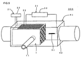
- FIG. 5 is a perspective view schematically showing still another embodiment of a reactor of the present invention.
- a reactor 100 of the present embodiment is provided with a honeycomb-structured reformer 1 having partition walls 3 separating and forming a plurality of cells 2 functioning as fluid passages extending through from one end face to the other end face, having a liquid supply hole 6 having an opening portion 5 on a side face 4, capable of evaporating liquid supplied inside, and capable of reforming the evaporated liquid; a liquid supply tube 11 inserted into the liquid supply hole 6 in order to supply liquid to the reformer 1; and a heating apparatus 21 for heating the reformer 1.
- Fig. 1 is a perspective view schematically shown an embodiment of the reactor 100 of the present invention.
- Fig. 2 is a plan view of the reactor 100 shown in Fig. 1 , viewed from the heater 21 side. Incidentally, in Fig. 2 , the heater 21 and the power source 22 for the heater shown in Fig. 1 are omitted.
- a liquid is supplied to the inside from the side face of the honeycomb structured reactor, and the reformer itself is heated by a heating apparatus, the liquid can be evaporated at the moment of supplying a liquid to the reformer, and the evaporated liquid can be reformed in the reformer.
- to reform a liquid means to generate hydrogen by reaction of hydrocarbon or alcohol in the liquid and to obtain a mixture containing hydrogen from the liquid. Therefore, the "liquid" reformed by a reactor of the present invention contains hydrocarbon or alcohol, and it is preferable to contain hydrocarbon.
- a partial oxidation reaction, a steam-reforming reaction, or the like can be employed as the reforming reaction.
- a reformer 1 has partition walls 3 separating and forming a plurality of cells 2 functioning as fluid passages extending through from one end face to the other end face. It is a honeycomb structure having a rectangular parallelepiped external shape.
- a liquid supply hole 6 having an opening portion 5 on a side face 4 is formed in the reformer 1.
- the side faces 4 of the reformer 1 are the outer peripheral faces other than both the end faces where opening portions of the cells are formed.
- the external shape of the reformer is preferably rectangular parallelepiped, it may be another shape such as a polygonal columnar shape other than one having a square bottom face and a circular cylindrical shape.
- a desired shape may suitably be selected from a circle, an ellipse, a triangle, a rectangle, and other polygons in a cross section perpendicular to the central axial direction.
- the cell shape is a rectangle in a cross section perpendicular to the central axial direction.
- the cell density of the honeycomb structured reformer is not particularly limited and may suitably be designed in accordance with the purpose. For example, it is preferably within the range from 6 to 2000 cells/sq. in. (1.0 to 320 cells/cm 2 ) .
- the cell density is below 6 cells/sq. in., strength of the partition walls or even strength of the reformer itself becomes insufficient, and, further, the effective GSA (geometric surface area) may be insufficient.
- GSA geometric surface area
- pressure loss may increase.
- the thickness of the partition walls is not particularly limited and may suitably be designed in accordance with the purpose.
- the wall thickness is preferably 50 ⁇ m to 2 mm, more preferably 60 to 500 ⁇ m.
- the wall thickness is less than 50 ⁇ m, mechanical strength is decreased, and it may become weak against thermal stress due to a shock or a temperature change.
- the rate of the cell capacity occupying the reformer is decreased, and pressure loss may become large.
- the length of the reformer (length in the direction where the cells extend (central axial direction)) is preferably 5 to 100 mm, more preferably 10 to 50 mm. When it is below 5 mm, most of the liquid may flow out from the reforming reactor without being reformed. When it is above 100 mm, the whole reactor becomes large because the reformer itself is large, and it is inappropriate for the application for an in-car liquid reformer, which is required to be small and light. It is preferable that the length of the reformer is suitably selected within the aforementioned range.
- the material for the reformer is preferably ceramic, and silicon carbide is further preferable among ceramic materials.
- the reformer preferably has a porous body having a porosity of 30 to 60% and further preferably has a porous body having a porosity of 40 to 50%.
- the porosity is a value measured by mercury porosimetry.
- the reformer 1 has plugging portions on one end portion of each of the predetermined cells 2 and the other end portion of each of the other cells 2 and that the predetermined cells are disposed only for one cell in the outermost periphery. It is preferable that it has plugging portions because the adiabatic effect improves.
- the material for the plugging portions is preferably the same as that for the partition walls of the reformer.
- the liquid supply hole 6 formed in the reformer 1 in the reactor 100 of the present embodiment is formed in order to insert the liquid supply tube 11 to introduce the liquid into the reformer 1. As shown in Figs. 1 and 2 , it is preferable that the liquid supply hole 6 is formed so as to have an opening portion on a side face 4 of the reformer 1 and extend through the reformer perpendicularly to the direction where the cells 2 extend.
- the length of the liquid supply hole 6 in the longitudinal direction is preferably 40 to 100% of the width of the honeycomb structured reformer 1. When it is below 40%, since the range where the liquid is supplied is narrow, the amount of reforming the liquid may be small.
- the "width of the reformer” means a distance from the position where an opening portion of the liquid supply hole is formed to the position where the end of the liquid supply hole crosses a side face of the reformer when the end of the liquid supply hole is extended in the longitudinal direction.
- the shape of a cross section perpendicular to the longitudinal direction of the liquid supply hole 6 is preferably a circle, it may be a polygon such as a triangle and a quadrangle, an ellipse, or the like.
- the size of the cross section perpendicular to the longitudinal direction of the liquid support hole 6 is preferably 1 to 4 mm, more preferably 2 to 3 mm, in diameter when the shape of the cross section is a circle. When it is below 1 mm, the supply amount of the liquid may be small, while, when it is above 4 mm, internal pressure is hardly applied to the liquid to easily cause dripping.
- the position for forming the liquid supply hole on a side face 4 of the reformer 1 is the position of 20 to 30% of the whole length in the cell extension direction from the end face where the carrier gas flows in and the position of 50% ⁇ 1% of the length in the direction perpendicular to the cell extension direction.
- the "face where the carrier gas flows in” will be described later in "3. method for using reactor”.
- the diameter of the cross section perpendicular to the longitudinal direction of the liquid supply hole 6 should be larger than the diameter of a cross section perpendicular to the longitudinal direction of the liquid supply tube 11, and the difference is preferably 3 to 15 mm, more preferably 5 to 10 mm.
- the liquid may hardly spread in the reformer.
- the reformer area becomes small, and the reformulation amount may be decreased.
- the heating apparatus 21 is constituted of a planar heater 22 and a power source 23 for the heater.
- the heating apparatus 21 heats the reformer 1 by the heat generation of the planar heater 22.
- the heater 22 is not limited to be planar and may be band shaped and wound around the reformer.
- the material is preferably an insulating one, which is power saving and has high output (temperature is highly raised).
- the power source 23 for heating may be a direct current or an alternate current, and, it is preferable to use a direct current stabilization power source when it is a direct current and a transformer or a variable transformer when it is an alternate current. It is more preferable to use an alternate current power source without polarity.
- the planar heater 22 is disposed on a side face 4 of the reformer 1.
- the area of the heater 22 is preferably 80 to100%, more preferably 90 to 100%, of the whole area of the upper face of the reformer 1. When it is below 80%, it may be difficult to sufficiently heat the reformer. When it is above 100%, it may hit the reformer-supporting member.
- the heater 22 is disposed on the upper face parallel to the direction where the liquid supply hole 6 extends.
- there is only one heater 22 there is only one heater 22. However, it is preferable that another heater is further disposed on the lower face parallel to the upper face where the heater 22 shown in Fig.
- the heater 22 generates heat within the range of preferably 750 to 950°C, more preferably 800 to 900°C. When it is below 750°C, the liquid is hardly evaporated, and the reforming reaction may hardly be caused. When it is above 950°C, breakage of the heater is easily caused, and the life may become short.
- the shape of the liquid supply tube 11 is preferably a circular cylinder having a hollow portion 12 for circulating the liquid as shown in Fig. 3 , it may be a parallelepiped having a polygonal bottom face, a cylinder having an elliptic bottom face, or the like.
- the length of the liquid supply tube 11 is not particularly limited as long as it can supply the liquid to the inside of the reformer with being inserted into the liquid supply hole, it is preferable that the liquid supply tube 11 protrudes from the opening portion of the liquid supply hole by 40 to 50 mm when the liquid supply tube 11 is inserted into the liquid supply hole up to a desired position.
- the diameter (outer diameter) of the cross section perpendicular to the longitudinal direction is preferably 6 to 8 mm.
- the inner diameter (diameter of the hole) in the cross section perpendicular to the longitudinal direction of the liquid supply tube 11 is preferably 2 to 4 mm, more preferably 2.9 to 3.1 mm.
- the thickness of the wall of the liquid supply tube 11 is preferably 1.6 to 3 mm, more preferably 1.9 to 2.1 mm. When it is thinner than 1.6 mm, strength of the liquid supply tube 11 may be decreased.
- Fig. 3 is a perspective view schematically shown the liquid supply tube 11 constituting one embodiment of a reactor of the present invention.
- the liquid supply tube 11 preferably has a liquid injection port 13 communicating with the hollow portion 12 within the range where the tube 11 is inserted in the liquid supply hole. It is preferable that a plurality of liquid injection ports 13 are formed and that they are formed to align in the central axial direction. In addition, as shown in Fig. 3 , in addition to the two liquid injection ports 13a, 13a aligned in the central axial direction, it is further preferable that two other liquid injection ports 13b, 13b aligned in the central axial direction are formed. In this case, there are four liquid injection ports in total.
- the angle formed by the "liquid injection port 13a on one side", the “center (center of the liquid supply tube)", and the “liquid injection port 13b on the other side” is preferably 30 to 120°, more preferably 60 to 90° in a cross section perpendicular to the central axial direction.
- the angle is below 30°, the liquid concentrates only in the central portion of the reformer, which may make evaporation difficult.
- the liquid concentrates in both the ends of the reformer, which may decrease the reformulation amount.
- the distance is preferably 10 to 20 mm, more preferably 14 to 16 mm.
- the distance from the end portion on the side where the tube is inserted into the liquid supply hole to the first liquid injection hole is preferably 5 to 10 mm, more preferably 6.5 to 7.5 mm.
- the diameter of the liquid injection port is preferably 1 to 3 mm, more preferably 1.9 to 2.1 mm. When it is smaller than 1 mm, it may become difficult to sufficiently supply the liquid, while, when it is larger than 3mm, dripping of the liquid may be caused.
- the material for the liquid supply tube 11 is preferably alumina or zirconia because of its excellent thermal resistance and corrosion resistance.
- a liquid-reforming catalyst is loaded on the reformer.
- the catalyst include materials containing at least one element selected from the group consisting of noble metals, aluminum, nickel, zirconium, titanate, cerium, cobalt, manganese, zinc, copper, tin, iron, niobium, magnesium, lanthanum, samarium, bismuth, and barium.
- the aforementioned noble metal is preferably at least one element selected from the group consisting of platinum, rhodium, palladium, ruthenium, indium, silver, and gold.
- the substances containing the aforementioned element include various forms of metal simple substances, metal oxides, and other compounds (chlorides, sulfates, and the like). These substances may be used alone or as a combination of two or more kinds.
- the catalyst is preferably loaded on the partition walls of the reformer. By loading the catalyst inside the cells of the reformer where the evaporated liquid passes, improvement in the reaction efficiency can be tried. In addition, unlike the packed-bed system, where a particle-shaped catalyst is filled, the passage of the evaporated liquid is hardly hindered since the cells functioning as gas passages are secured. In addition, since a catalyst component is loaded on the reformer as a substrate, it has good heat transfer in the catalyst.
- the amount of loaded catalyst is preferably 0.05 to 70 [g (catalyst mass) / L (reformer volume)], more preferably 0.1 to 40 g/L.
- the amount is below 0.05 g/L, the catalyst function may hardly be exhibited.
- the production costs for the reactor may increase.
- the catalyst is preferably loaded on the partition walls of the reformer in the state of a catalyst-coated microparticle loaded on a carrier microparticle.
- a carrier microparticle there can be used, for example, a ceramic powder.
- a ceramic powder there is no particular limitation on the kind of the ceramic, and there can suitably be used a powder of, for example, metal oxides, in particular, silica, alumina, titania, zirconia, ceria, zeolite, mordenite, silica alumina, metal silicate, cordierite, or the like. These ceramic materials may be used alone or as a combination of two or more kinds.
- Such a catalyst-coated microparticle can be loaded by coating it on the partition walls of the reformer.
- the average particle diameter of the aforementioned carrier microparticle is preferably 0.01 to 50 ⁇ m, more preferably 0.1 to 20 ⁇ m.
- the catalyst may hardly be loaded on the surface of the carrier microparticle.
- the catalyst-coated microparticle may easily be peeled off.
- the mass ratio of the catalyst to the carrier microparticle is preferably 0.1 to 20 mass%, more preferably 1 to 10 mass%.
- the mass ratio of the catalyst is below 0.1 mass%, the reforming reaction may hardly proceed.
- the catalyst when it is above 20 mass%, since the catalyst easily agglutinates without being uniformly dispersed, the catalyst may hardly be loaded uniformly on the carrier microparticle. Therefore, even if the catalyst at an amount exceeding 20 mass% is added, the catalyst addition effect corresponding with the amount cannot be obtained, and there is a case that the reforming reaction is not accelerated.
- the catalyst-coated microparticle can be obtained by, for example, impregnating a ceramic powder to serve as a carrier microparticle with an aqueous solution containing a catalyst component, followed by drying and firing. To the catalyst-coated microparticles are added a dispersion medium (water or the like) and other additives to prepare coating liquid (slurry), and the slurry is coated on the partition walls of the reformer to load the catalyst on the partition walls of the reformer.
- a dispersion medium water or the like
- the reactor 200 of the present embodiment is provided with a honeycomb structured reformer 1, a liquid supply tube 11, and a heating apparatus 21.
- the heating apparatus 21 has a linear electrode 31 disposed on an extended line of the direction where the cells of the reformer 1 extend and a pulse power source 32 capable of applying pulse voltage to a pair of electrodes with the reformer and the linear electrode being regarded as the pair of electrodes.
- the reformer 1 By employing conductive ceramic as the material for the reformer 1 and by generating plasma by applying pulse voltage from the pulse power source 32 between a pair of electrodes with the linear electrode 31 and the reformer 1 being a pair of electrode, the reformer 1 is heated to accelerate the evaporation and reforming reaction of the liquid.
- the characteristics of the reformer 1 and the liquid supply tube 11 are the same as the characteristics of the reformer 1 and the liquid supply tube 11 in the aforementioned one embodiment of a reactor of the present invention. Incidentally, in the reformer, the constitution suitable for generating plasma will further be described below.
- the characteristics of the catalyst loaded are the same as the characteristics of the catalyst in the aforementioned one embodiment of a reactor of the present invention.
- the reformer is heated by the use of the linear electrode and the pulse power source as the heating apparatus, since the reformer to be heated is also used as one of the electrodes where pulse voltage is applied, the reformer, also, can be considered as a part of the heating apparatus.
- Fig. 4 is a perspective view schematically showing another embodiment of a reactor of the present invention.
- the reactor 200 of the present embodiment Since the reactor 200 of the present embodiment generates plasma by applying pulse voltage between the reformer of conductive ceramic and the linear electrode, the reformer is heated by the generation of plasma, and the reformulation of the liquid is accelerated by the plasma. By this, when a liquid is supplied to the reformer, the liquid is evaporated in the reformer, and the evaporated liquid is reformed.
- silicon carbide is suitable as the conductive ceramic, which is the material for the reformer 1.
- the reformer 1 is made of conductive ceramic containing silicon carbide.
- the content rate of silicon carbide in the reformer 1 is preferably 50 mass% or more, more preferably 60 mass% or more from the reason of suppressing deterioration in conductivity.
- the reformer 1 When the reactor 200 of the present embodiment is used for hydrogen formation by reforming of hydrocarbon, the reformer 1 has a cell density of preferably 25 to 1163 cells/sq.in. (4 to 186 cells/cm 2 ). When the cell density is below 4 cells/cm 2 , the generation region of plasma performing creeping discharge becomes sparse on a surface of the partition walls of each cell, and the liquid-reforming efficiency may decrease. When it is above 186 cells/cm 2 , back pressure resistance may increase.
- the electric resistance is preferably 2 ⁇ or less, more preferably 0.3 ⁇ or less upon applying a voltage of 3.5V at 180°C.
- silicon carbide as conductive ceramic and to subject it to a treatment of mixing metal silicon, compounding metal silicon with silicon carbide, or the like.
- the "electric resistance” here means a value obtained by measuring (180°C) a rectangular parallelepiped having a length of 3.3 cm and a cross-sectional area of 1.1 cm 2 (cross-sectional area of a cross section perpendicular to the cell extension direction) obtained by cutting the reformer 1 along the cell extension direction of the reformer 1 with a voltage terminal distance of 2.3 cm in a constant current 4-terminal method using a direct-current power source.
- the reformer 1 has a thermal conductivity of preferably 5 to 300 W/mK, more preferably 10 to 200 W/mK, particularly preferably 20 to 100 W/mK from the viewpoint of activation of the loaded catalyst.
- a thermal conductivity preferably 5 to 300 W/mK, more preferably 10 to 200 W/mK, particularly preferably 20 to 100 W/mK from the viewpoint of activation of the loaded catalyst.
- the thermal conductivity is below 5 W/mK, much time may be spent for the activation of the loaded catalyst.
- heat release to the outside increases, and the loaded catalyst may insufficiently be activated.
- the conductive ceramics having such a thermal conductivity include silicon carbide, silicon nitride, and aluminum nitride.
- the reformer is disposed in such a manner that the interelectrode distance from the linear electrode 31 is preferably 1 to 30 mm, more preferably 5 to 10 mm.
- the interelectrode distance is below 1 mm, electric field concentration is easily caused, and short-circuiting may easily be caused with the concentration being the starting point.
- plasma discharge is caused between the electrodes, the hydrogen generation amount according to the reforming reaction of hydrocarbon may be decreased.
- it is above 30 mm plasma discharge is hardly stabilized, and the plasma generation efficiency may be decreased.
- the linear electrode 31 is preferably a stick-shaped or needle-shaped electrode.
- the "stick-shape” means a linear circular column
- the “needle-shape” means a shape having a pointed tip portion in the aforementioned "stick-shape”.
- the shape of the linear electrode is not necessarily limited to a linear shape as in the stick-shaped electrode or the needle-shaped electrode.
- it may be a bent shape including an L shape.
- the number of the linear electrode may one or a plurality.
- the linear electrode 31 is preferably disposed in such a manner that the central axial direction (longitudinal direction) is parallel to the cell extension direction of the reformer.
- the linear electrode has a bent shape, it is preferably disposed in such a manner that the linear portion including the tip portion toward the reformer side among the linear portions formed by the bending is parallel to the cell extension direction of the reformer.
- the length of the linear electrode is preferably 3 to 50 mm, more preferably 5 to 30 mm from the reason of reducing the size of the reactor.
- the length is below 3 mm, handling of the linear electrode is unstable upon manufacturing the reactor, and fixation of the linear electrode may be difficult.
- the linear electrode may easily be bent by the contact with the circulation gas circulating in the reformer.
- the linear electrode has an outer diameter of preferably 0.1 to 5 mm, more preferably 0.5 to 3 mm.
- the outer diameter is below 0.1 mm, the linear electrode is easily bent by the contact with the circulation gas circulating in the reformer, and plasma discharge may become unstable.
- it is above 5 mm, it may become difficult to control plasma discharge.
- the linear electrode is preferably constituted of a material having high conductivity, specifically, metals, alloys, conductive ceramics, etc., from the viewpoint of securing conductivity.
- metals having high conductivity include nickel, copper, aluminum, and iron.
- alloys having high conductivity include aluminum-copper alloy, titanium alloy, stainless steel, and Inconel (trade name).
- conductive ceramics include silicon carbide. Examples of other materials include carbon.
- the pulse power source 32 is a power source for applying pulse voltage to a pair of electrodes.
- any power source can be employed as long as voltage can be applied periodically, it is preferably a power source capable of supplying (a) a pulse waveform having a peak voltage of 1 kV or more and a pulse number of 1 or more per 1 second, (b) an alternating-current voltage waveform having a peak voltage of 1 kV or more and a frequency of 1 Hz or more, (c) a direct-current waveform having a voltage of 1 kV or more, or (d) a voltage waveform obtained by superimposing any of these waveforms.
- the power source has a peak voltage of preferably 1 to 20 kV, and it is more preferable to employ a power source having a peak voltage of 5 to 10 kV.
- Examples of such a power source include a high-voltage pulse power source (produced by NGK, Insulators, Ltd.) using a static induction thyristor (SI thyristor).
- a reactor of the present invention has a reformer 1 therein and is provided with a reforming reactor 41, which is a tubular structure having a circulation gas introduction port 42 and discharge port for the circulation gas containing reformed gas.
- a reforming reactor 41 which is a tubular structure having a circulation gas introduction port 42 and discharge port for the circulation gas containing reformed gas.
- the reforming reactor 41 has a hollow shape because of necessity of passing the gas, there is no other limitations regarding the shape, and, a structure having, for example, a cylindrical shape or a parallelepiped shape may be employed.
- the maximum inner diameter of the reforming reactor is not particularly limited, and the size may suitably be determined according to the intended use of the reactor.
- Fig. 5 is a perspective view schematically showing still another embodiment of a reactor of the present invention.
- the reformer 1 is preferably disposed in the reforming reactor 41 in such a manner that the two end faces where cells are open face the circulation gas inlet port 52 side and the circulation gas discharge port.
- a container portion is preferably constituted of metal having good processability (e.g., stainless steel).
- a portion for arranging the reactor in the container and the like is preferably constituted of an "insulating material" from the viewpoint of inhibiting short-circuiting.
- a ceramic material can suitably be used.
- the ceramic material it is preferable to use alumina, zirconia, silicon nitride, aluminum nitride, sialon, mullite, silica, cordierite, or the like. These ceramic materials may be used alone or as a combination of two or more kinds.
- the characteristics of the reactor 1 and the liquid supply tube 11 are the same as the characteristics of the reactor 1 and the liquid supply tube 11 in the aforementioned one embodiment of a reactor of the present invention.
- the constitution suitable for generating plasma is the same as in the reactor 1 in another embodiment of a reactor of the present invention.
- the characteristics of the catalyst to be loaded are the same as the characteristics of the catalyst in the aforementioned one embodiment of a reactor of the present invention.
- the heating apparatus both the heating apparatus using a heater and the heating apparatus using a pulse power source and a linear electrode are used.
- the characteristics of the heating apparatus using a heater are the same as the characteristics of the heating apparatus using a heater in the aforementioned one embodiment of a reactor of the present invention.
- the characteristics using a pulse power source and a linear electrode are the same as the characteristics of the heating apparatus using a pulse power source and a linear electrode in the aforementioned another embodiment of a reactor of the present invention.
- a reactor of the present invention employs both the heating apparatus 21 using a heater 22 and the heating apparatus 21 using a pulse power source 32 and a linear electrode 31 because evaporation of the liquid and reformulation of the evaporated liquid can effectively be performed.
- the reformer can be manufactured by a known extrusion-forming method. Specifically, kneaded clay containing a ceramic powder is subjected to extrusion forming to manufacture a desired honeycomb formed article, and the honeycomb formed article is subjected to a hole-making process to form a liquid supply hole, followed by drying and firing to obtain a honeycomb structured reformer.
- the ceramic powder it is preferable to use the ceramic powder mentioned as the preferable material for the reformer in the aforementioned one embodiment or another embodiment of a reactor of the present invention.
- plugging portions are preferably formed in predetermined portions on both the end faces where cells are open of the reformer.
- the method for forming the plugging portions an example is the following method. After a sheet is attached to one end face (end face on one side where cells are open) on one side of a fired reformer, holes are made in portions corresponding with the cells (first cells) where the plugging portions are to be formed of the sheet. Then, the end face having the sheet attached thereto of the fired reformer is immersed in plugging slurry obtained by slurrying a constituent material for the plugging portions to fill the plugging slurry into the opening end portions of the cells (first cells) where the plugging portions are to be formed through the holes made in the sheet.
- plugging portions are formed (plugging slurry is filled) in the cells (second cells) each not having the plugging portion on an end face on the one side in the same manner as in the method of forming plugging portions on the end face on the one side.
- the constituent material for the plugging portions the same material as that for the honeycomb formed article is preferably used. It is preferable to perform firing under the same conditions as the aforementioned conditions after the plugging portions are formed.
- the plugging portions may be formed before firing the honeycomb formed article.
- the liquid supply tube can be obtained by manufacturing a desired tubular formed article by subjecting kneaded clay containing a ceramic powder to extrusion forming and a liquid injection port is formed in the tubular formed article, followed by drying and firing.
- a ceramic powder used for manufacturing of the liquid supply tube it is preferable to use the ceramic powder mentioned as the preferable material for the liquid supply tube in the aforementioned one embodiment of a reactor of the present invention.
- the liquid injection port may be formed after firing the aforementioned tubular forming article.
- the reforming reactor by processing a metal into a desired shape in that metal can easily be processed.
- alumina or the like as the insulating material is disposed inside the reforming reactor and that the reformer is disposed on the insulating material.
- the reforming reactor itself may be formed by forming the insulating material.
- the reforming reactor is manufactured by forming alumina or the like as the insulating material, it is preferable to obtain a tubular (cylindrical) reforming reactor by subjecting kneaded clay containing a ceramic powder to extrusion into a desired shape, followed by drying and firing.
- a catalyst on the partition walls of the reformer it is preferable to load a catalyst on the partition walls of the reformer.
- the ceramic powder serving as a carrier microparticle is impregnated with an aqueous solution containing a catalyst component in advance, drying and firing are performed to obtain a catalyst-coated microparticle.
- a dispersion medium water or the like
- other additives to prepare coating liquid (slurry), and the slurry is coated on the partition walls of the reformer, followed by drying and firing to load the catalyst on the partition walls of the reformer.
- the thus obtained reformer is placed in the inner space of the reforming reactor, and the liquid supply tube is connected with the reformer.
- a predetermined heater is disposed on a side face of the reactor and electrically connected with the power source for the heater to obtain a reactor.
- the linear electrode is disposed apart from the reformer at a predetermined distance on the extension of the cell extending direction. Then, the honeycomb electrode and the linear electrode are electrically connected with the pulse power source to obtain a reactor.
- the linear electrode is preferably disposed in such a manner that the longitudinal direction is parallel to the cell extension direction.
- a reactor of the present invention can suitably be used for a reforming reaction, in particular, the reforming reaction for obtaining hydrogen-containing reformed gas from a liquid containing a hydrocarbon based compound or an alcohol.
- hydrocarbon based compound examples include light hydrocarbons such as methane, propane, butane, heptane, and hexane and petroleum hydrocarbons such as isooctane, pentadecane, gasoline, kerosene, and naphtha.
- alcohol examples include methanol, ethanol, 1-propanol, 2-propanol, and 1-butanol.
- the liquid may contain one of these hydrocarbon components and alcohols or a combination thereof. It is also possible that the liquid is constituted of only the hydrocarbon compounds or the alcohols, and, in that case, only one kind out of the hydrocarbon compounds or the alcohols may be used alone, or two or more kinds may be mixed together.
- the reforming method can be used in any of the partial reformulation using oxygen, steam reformulation using water, auto thermal using oxygen and water, and the like.
- carrier gas is introduced from an end face on one side of the end faces where cells are open of the reformer and allowed to pass through the cells and disposed from the end face on the other side.
- the end face where the carrier gas is introduced is the "face on the side where the carrier gas flows in".
- the carrier gas it is preferable to use nitrogen gas, argon gas, or the like.
- oxygen it is preferable to be contained in the carrier gas at a predetermined rate.
- steam reformulation it is preferable to allow water to be contained in the carrier gas. Then, the reformer is heated at a predetermined temperature with a heating apparatus.
- the temperature of the reformer is preferably 600 to 700°C for the partial reformation or 400 to 600°C for the steam reformation.
- the liquid is supplied to the inside of the reformer with the liquid supply tube.
- the liquid supplied to the inside of the heated reformer is evaporated, and the evaporated liquid is reformed in the reformer to become reformed gas containing hydrogen.
- the reformed gas means a mixture of hydrogen and another compound obtained by reformulation of liquid. Then, the reformed gas is discharged from the end face on the other side of the reformer together with carrier gas.
- pulse voltage having a voltage waveform selected from (a) a pulse waveform having a peak voltage of 1 kV or more and a pulse number of 1 or more per 1 second, (b) an alternating-current voltage waveform having a peak voltage of 1 kV or more and a frequency of 1 Hz or more, (c) a direct-current waveform having a voltage of 1 kV or more, and (d) a voltage waveform obtained by superimposing any of these waveform.
- a reactor as shown in Fig. 5 was manufactured.
- a honeycomb structure made of silicon carbide (SiC) silicon carbide honeycomb structure
- SiC silicon carbide honeycomb structure
- the 33 mm cube silicon carbide DPF is manufactured on mass production lines as a 33 mm cube segment.
- the “length” means the length in the cell extension direction
- the “horizontal size” means a length in the direction where the liquid supply hole extends
- the “vertical size” means a length in the direction perpendicular to the directions for the "length” and the “horizontal size”.
- a catalyst was loaded on the reformer.
- the method for loading the catalyst was as follows. In the first place, a finely-powdered alumina (specific surface area of 107 m 2 /g) was impregnated with a nickel nitrate (Ni(NO 3 ) 2 ) solution, followed by drying at 120°C and firing at 550°C for 3 hours in the atmosphere to obtain a nickel/alumina powder containing 20 mass% of nickel (Ni) with respect to alumina. After alumina sol and water were added to the nickel/alumina powder, the pH was adjusted to be 4 with a nitric acid solution to obtain slurry.
- Ni(NO 3 ) 2 nickel nitrate
- a reformer was immersed in the slurry and dried at 120°C, followed by firing at 550°C for one hour in a nitrogen atmosphere to manufacture a reformer having a catalyst loaded thereon. At this time, the amount of nickel loaded on the reformer was 50 (g/L).
- the liquid supply tube was manufactured by subjecting a forming raw material containing an alumina powder to extrusion forming into a cylindrical shape, followed by drying, firing, and forming a liquid injection port (alumina purity of 96%).
- a forming raw material containing an alumina powder In the liquid supply tube, an opening portion in an end portion on one side was closed with Aron Ceramic D (produced by Toagosei, Co., Ltd.).
- the liquid supply tube obtained above had an outer diameter of 7.2 mm and an inner diameter of 3.0 mm.
- the liquid injection ports were formed in the positions of 7 mm and 17 mm from the closed end portion, and two more liquid injection ports were formed in the positions having an angle of 90° from the aforementioned two positions.
- a liquid supply tube having four liquid injection ports formed thereon as shown in Fig. 3 was obtained.
- the liquid supply tube was fixed to the liquid supply hole 6 in such a manner that the central position of the four positions having the liquid injection ports faces the direction of the reformer 1 in
- a planar heater (produced by SAKAGUCHI E.H VOC CORP.) was used as a heater.
- the power source for the heater the power source attached to the planar heater was used.
- the planar heater had a vertical size of 25 mm, a horizontal size of 25 mm, and a thickness of 2 mm. As shown in Fig. 5 , the planar heater was fixed on the reformer with being directly put thereon.
- a linear electrode 31 and a pulse power source 32 were used together with a heater 22.
- the reformer 1 functions as an electrode for generating plasma, it was made of silicon carbide, which is a conductive ceramic.
- the pulse power there was used a high voltage pulse power source using a static induction (SI) thyristor (produced by NGK Insulators, Ltd.) as a switching element.
- the linear electrode a circular columnar stainless steel electrode with a cross section perpendicular to the longitudinal direction having a diameter of 0.5 mm and a length of about 10 mm. The linear electrode was used on the positive electrode side, and the reformer was used on the negative electrode side.
- a reforming reactor having the reformer disposed therein was manufactured.
- a stainless steel plate having a thickness of 5 mm was processed into a rectangular parallelepiped shape (box shape) having a vertical (circulation direction of circulation gas) size of 90 mm, a horizontal size of 70 mm, and a depth of 25 m. Holes each having a diameter of 20 mm were formed in the two faces perpendicular to the fluid circulation direction, and one of the holes was determined as the circulation gas introduction port 42, and the other hole was determined as the circulation gas discharge port.
- An insulating plate for arranging the reformer thereon was disposed on an inner face of the reforming reactor. As the insulating plate, an alumina plate was used.
- a reformer 1 was disposed inside the reforming reactor 41, and a linear electrode 31 was disposed in a position 5 mm apart from the end face (end face where opening portions of cells are formed) on the circulation gas inlet side of the reformer 1, followed by electrically connecting a pulse power source to the linear electrode (positive electrode) and the reformer (negative electrode) with a conductive wire to obtain a reactor.
- a hydrocarbon reformulation test was performed by the method shown below. The results are shown in Table 1.
- power consumption means the total amount of energy used in the heating apparatus and the plasma.
- Pentadecane (C 15 H 32 ) was used as the liquid to be reformed, and pentadecane was reformed by a partial oxidation reaction to generate hydrogen and carbon monoxide.
- Nitrogen gas containing oxygen at 15000 ppm was allowed to flow in from the circulation gas introduction port 42 of the reforming reactor 41 as the carrier gas, and the carrier gas flowing into the reforming reactor 41 was allowed to flow in the reformer from openings of cells on an end face on one side of the reformer, passed through the cells, and discharged from the end face on the other side of the reformer.
- the carrier gas discharged from the reformer was discharged from the circulation gas discharge port of the reforming reactor 41.
- the carrier gas was heated at 350°C before it was allowed to flow into the reforming reactor.
- liquid pentadecane was supplied to the reformer 1 from the liquid supply tube 11 at a prescribed rate by the use of a high pressure microfeeder (JP-H type produced by Furue Science Co., Ltd.) to evaporate pentadecane in the reformer.
- the carrier gas had a composition of "pentadecane of 2000 ppm, oxygen of 15000 ppm, and nitrogen as the rest". The composition ratio was before reformulation.
- the space velocity (SV) of the carrier gas was 80000/hour with respect to the plasma generation space of the reformer.
- the hydrogen content in the carrier gas discharged from the circulation gas discharge port of the reforming reactor 41 was measured with a gas chromatography (GC3200 produced by GL Science Inc., using argon gas as the carrier gas) provided with a TCD (thermal conductivity detector) to calculate ahydrogenproduction rate.
- the hydrogen production rate was calculated by dividing the pentadecane amount converted from the hydrogen content measured above in the carrier gas by the amount of pentadecane supplied to the carrier gas and multiplying the value by 100.
- a repetition cycle was 3 kHz, and a peak voltage of 3 kV was applied between the electrodes.
- the planar heater disposed in the reformer was heated for temperature adjustment to adjust the temperature of the carrier gas discharged from the reformer to be 350°C.
- Table 1 Example 1 Comp. Ex. 1 Hydrogen production rate (%) 50 45 Power consumption (W) 150 280
- a reactor was manufactured in the same manner as in Example 1 except that linear electrodes were manufactured in place of the reformer to reform pentadecane by the use of two linear electrodes as a pair of plasma generation electrodes. The distance between the electrodes was 5 mm.
- the reforming test was performed in the same manner as in Example 1. Incidentally, the liquid pentadecane was heated and evaporated with a planar heater just before the circulation gas inlet port.
- Example 1 From Table 1, it can be understood that the reactor in Example 1 can achieve high hydrogen production rate with low power consumption in comparison with the reactor in Comparative Example 1.
- a reactor of the present invention can suitably be used as an apparatus for generating hydrogen by reforming a liquid.
Landscapes
- Chemical & Material Sciences (AREA)
- Chemical Kinetics & Catalysis (AREA)
- Organic Chemistry (AREA)
- Engineering & Computer Science (AREA)
- Combustion & Propulsion (AREA)
- Health & Medical Sciences (AREA)
- General Health & Medical Sciences (AREA)
- Inorganic Chemistry (AREA)
- Physics & Mathematics (AREA)
- Electromagnetism (AREA)
- Mechanical Engineering (AREA)
- Toxicology (AREA)
- Hydrogen, Water And Hydrids (AREA)
- Physical Or Chemical Processes And Apparatus (AREA)
- Fuel Cell (AREA)
- Catalysts (AREA)
- Plasma Technology (AREA)
Claims (9)
- Reaktor, umfassend:einen Reformer (1) mit Wabenstruktur, der Trennwände (3) aufweist, die eine Vielzahl von Zellen (2) trennen und ausbilden, die als Fluiddurchlässe fungieren, die sich von einer Endfläche zu einer anderen Endfläche erstrecken, und eine Seitenfläche aufweist, die sich von der einen Endfläche zur anderen Endfläche erstreckt, und der ferner ein Flüssigkeitszufuhrloch (6) mit einer Öffnung auf der Seitenfläche aufweist, wobei der Reformer (1) in der Lage ist, eine innen zugeführte Flüssigkeit abzudampfen und die abgedampfte Flüssigkeit zu reformieren;einen Flüssigkeitszufuhrschlauch (11), der in das Flüssigkeitszufuhrloch (6) eingeführt ist, um den Zellen (2) innerhalb des Reformers (1) Flüssigkeit zuzuführen; undeine Heizvorrichtung (21) zum Erhitzen des Reformers (1).
- Reaktor nach Anspruch 1, worin die Flüssigkeit Kohlenwasserstoff enthält.
- Reaktor nach Anspruch 1 oder 2, worin die Heizvorrichtung (21) ein Heizgerät (22) aufweist, das auf der Seitenfläche des Reformers (1) angeordnet ist und der Reformer (1) vom Heizgerät (22) erhitzt wird, um die Abdampf- und Reformreaktion der Flüssigkeit zu beschleunigen.
- Reaktor nach einem der Ansprüche 1 bis 3, worin ein Material für den Reformer (1) ein leitfähiges Keramikmaterial ist und die Heizvorrichtung (21) eine lineare Elektrode (31) aufweist, die auf einer verlängerten Geraden in der Richtung angeordnet ist, in die sich die Zellen (2) des Reformers (1) erstrecken, und worin eine Pulsenergiequelle (32) in der Lage ist, eine Pulsspannung an ein Elektrodenpaar anzulegen, wobei der Reformer (1) und die lineare Elektrode (31) als das Elektrodenpaar anzusehen sind,
worin die Pulsspannung zwischen dem Elektrodenpaar angelegt ist, um Plasma zu erzeugen, wodurch der Reaktor (1) erhitzt wird, um die Abdampf- und Reformreaktion der Flüssigkeit zu beschleunigen. - Reaktor nach Anspruch 4, worin das leitfähige Keramikmaterial Silikoncarbid enthält.
- Reaktor nach einem der Ansprüche 1 bis 5, worin ein Katalysator zum Reformieren auf dem Reformer (1) geladen ist.
- Reaktor nach Anspruch 6, worin der Katalysator eine Substanz ist, die mindestens ein Element ausgewählt aus der Gruppe bestehend aus Edelmetallen, Aluminium, Nickel, Zirkonium, Titan, Cerium, Kobalt, Mangan, Zink, Kupfer, Zinn, Eisen, Niobium, Magnesium, Lanthan, Samarium, Wismuth und Barium enthält.
- Reaktor nach Anspruch 6, worin der Katalysator eine Substanz ist, die mindestens ein Element ausgewählt aus der Gruppe bestehend aus Platin, Rhodium, Palladium, Ruthenium, Indium, Silber und Gold enthält.
- Reaktor nach einem der Ansprüche 4 bis 8, worin die Pulsenergiequelle (32) eine Hochspannungspulsenergiequelle mit einem statischen Induktionsthyristor ist.
Applications Claiming Priority (1)
| Application Number | Priority Date | Filing Date | Title |
|---|---|---|---|
| JP2008308570A JP2010132482A (ja) | 2008-12-03 | 2008-12-03 | リアクタ |
Publications (2)
| Publication Number | Publication Date |
|---|---|
| EP2196258A1 EP2196258A1 (de) | 2010-06-16 |
| EP2196258B1 true EP2196258B1 (de) | 2013-07-03 |
Family
ID=42060661
Family Applications (1)
| Application Number | Title | Priority Date | Filing Date |
|---|---|---|---|
| EP09252638.3A Not-in-force EP2196258B1 (de) | 2008-12-03 | 2009-11-17 | Reaktor |
Country Status (3)
| Country | Link |
|---|---|
| US (1) | US20100135870A1 (de) |
| EP (1) | EP2196258B1 (de) |
| JP (1) | JP2010132482A (de) |
Families Citing this family (7)
| Publication number | Priority date | Publication date | Assignee | Title |
|---|---|---|---|---|
| JP4966887B2 (ja) * | 2008-02-14 | 2012-07-04 | 日本碍子株式会社 | プラズマ反応器、及びプラズマ反応装置 |
| US20120111315A1 (en) * | 2010-11-09 | 2012-05-10 | Exxonmobil Research And Engineering Company | In-situ vaporizer and recuperator for alternating flow device |
| BR112018002616B1 (pt) | 2015-08-10 | 2022-09-20 | Nissan Motor Co., Ltd. | Sistema de células a combustível de óxido sólido |
| CN113710610B (zh) * | 2019-04-23 | 2024-04-09 | 三菱电机株式会社 | 气体制造系统和气体制造方法 |
| CN110562917B (zh) * | 2019-10-18 | 2024-08-06 | 翁幼云 | 微型重整装置以及微型重整系统 |
| CN116371416B (zh) * | 2023-04-03 | 2024-05-03 | 安徽理工大学 | 一种镍-铌/凹凸棒石基有序介孔催化剂及其制备方法和应用 |
| US20250123160A1 (en) * | 2023-06-08 | 2025-04-17 | OmniCal, Inc. | Heating adiabatic calorimeter and methods of use |
Family Cites Families (19)
| Publication number | Priority date | Publication date | Assignee | Title |
|---|---|---|---|---|
| US4101287A (en) * | 1977-01-21 | 1978-07-18 | Exxon Research & Engineering Co. | Combined heat exchanger reactor |
| JP3208628B2 (ja) * | 1994-03-31 | 2001-09-17 | 日立造船株式会社 | プラズマ法排ガス浄化装置 |
| JP3843504B2 (ja) * | 1996-09-24 | 2006-11-08 | いすゞ自動車株式会社 | 触媒担体を持つアルコール改質装置 |
| ES2359884T3 (es) * | 1998-07-08 | 2011-05-27 | Toyota Jidosha Kabushiki Kaisha | Aparato para la reforma de combustibles. |
| HK1050885A1 (zh) * | 1999-07-29 | 2003-07-11 | 戴维系统技术公司 | 化石燃料轉化成富氫氣體的等離子體轉化器 |
| DE60114928T2 (de) | 2000-06-08 | 2006-07-06 | Toyota Jidosha K.K., Toyota | Brennstoffreformer |
| JP2004344719A (ja) * | 2003-05-20 | 2004-12-09 | Toyota Motor Corp | 排気浄化装置 |
| JP4329466B2 (ja) * | 2003-09-22 | 2009-09-09 | トヨタ自動車株式会社 | 排気浄化装置 |
| JP2006125313A (ja) * | 2004-10-29 | 2006-05-18 | Toyota Motor Corp | 燃料改質装置 |
| JP2006248847A (ja) * | 2005-03-10 | 2006-09-21 | Nissan Motor Co Ltd | 燃料改質器および燃料改質装置 |
| JP2007137721A (ja) | 2005-11-18 | 2007-06-07 | Nissan Motor Co Ltd | 燃料改質装置 |
| JP4766600B2 (ja) * | 2005-12-01 | 2011-09-07 | 日本碍子株式会社 | 水素製造装置 |
| JP4521513B2 (ja) * | 2006-01-30 | 2010-08-11 | 独立行政法人産業技術総合研究所 | 内部発熱式の熱交換構造体 |
| JP4619976B2 (ja) * | 2006-03-30 | 2011-01-26 | 日本碍子株式会社 | プラズマリアクタ |
| KR20100098505A (ko) * | 2007-10-30 | 2010-09-07 | 니뽄 가이시 가부시키가이샤 | 플라즈마 리액터 |
| JP2010131589A (ja) * | 2008-10-31 | 2010-06-17 | Ngk Insulators Ltd | ハニカム構造体及びハニカム構造体を用いたリアクタ |
| JP2010215468A (ja) * | 2009-03-18 | 2010-09-30 | Ngk Insulators Ltd | リアクタ |
| JP5261244B2 (ja) * | 2009-03-25 | 2013-08-14 | 日本碍子株式会社 | リアクタ |
| JP5064445B2 (ja) * | 2009-06-25 | 2012-10-31 | 日本碍子株式会社 | プラズマリアクタ |
-
2008
- 2008-12-03 JP JP2008308570A patent/JP2010132482A/ja active Pending
-
2009
- 2009-11-16 US US12/618,885 patent/US20100135870A1/en not_active Abandoned
- 2009-11-17 EP EP09252638.3A patent/EP2196258B1/de not_active Not-in-force
Also Published As
| Publication number | Publication date |
|---|---|
| US20100135870A1 (en) | 2010-06-03 |
| JP2010132482A (ja) | 2010-06-17 |
| EP2196258A1 (de) | 2010-06-16 |
Similar Documents
| Publication | Publication Date | Title |
|---|---|---|
| EP2213618B1 (de) | Plasmareaktor | |
| EP2272586B1 (de) | Plasmareaktor | |
| JP2010131589A (ja) | ハニカム構造体及びハニカム構造体を用いたリアクタ | |
| EP2196258A1 (de) | Reaktor | |
| JP5068191B2 (ja) | プラズマ反応器、及びプラズマ反応装置 | |
| US8053992B2 (en) | Plasma reactor and plasma reaction apparatus | |
| US6585940B2 (en) | Reformer | |
| US20090282817A1 (en) | Plasma processing apparatus | |
| JP2024518985A5 (de) | ||
| EP2088838B1 (de) | Plasmareaktor | |
| US8263011B2 (en) | Reactor | |
| US10960372B2 (en) | Catalytically heated fuel processor with replaceable structured supports bearing catalyst for fuel cell | |
| JP5261244B2 (ja) | リアクタ | |
| JP5620077B2 (ja) | 水素触媒部材 | |
| JP2012233443A (ja) | 排ガス浄化システム | |
| JP2010184197A (ja) | プラズマリアクタ | |
| CN118384821A (zh) | 一种泡沫电极结构的等离子体催化反应装置 | |
| KR20240013783A (ko) | 촉매 활성을 가진 전기 가열기 |
Legal Events
| Date | Code | Title | Description |
|---|---|---|---|
| PUAI | Public reference made under article 153(3) epc to a published international application that has entered the european phase |
Free format text: ORIGINAL CODE: 0009012 |
|
| AK | Designated contracting states |
Kind code of ref document: A1 Designated state(s): AT BE BG CH CY CZ DE DK EE ES FI FR GB GR HR HU IE IS IT LI LT LU LV MC MK MT NL NO PL PT RO SE SI SK SM TR |
|
| AX | Request for extension of the european patent |
Extension state: AL BA RS |
|
| 17P | Request for examination filed |
Effective date: 20101126 |
|
| RIC1 | Information provided on ipc code assigned before grant |
Ipc: B01J 19/24 20060101AFI20121109BHEP |
|
| GRAP | Despatch of communication of intention to grant a patent |
Free format text: ORIGINAL CODE: EPIDOSNIGR1 |
|
| GRAS | Grant fee paid |
Free format text: ORIGINAL CODE: EPIDOSNIGR3 |
|
| GRAA | (expected) grant |
Free format text: ORIGINAL CODE: 0009210 |
|
| AK | Designated contracting states |
Kind code of ref document: B1 Designated state(s): AT BE BG CH CY CZ DE DK EE ES FI FR GB GR HR HU IE IS IT LI LT LU LV MC MK MT NL NO PL PT RO SE SI SK SM TR |
|
| REG | Reference to a national code |
Ref country code: GB Ref legal event code: FG4D |
|
| REG | Reference to a national code |
Ref country code: CH Ref legal event code: EP Ref country code: AT Ref legal event code: REF Ref document number: 619384 Country of ref document: AT Kind code of ref document: T Effective date: 20130715 |
|
| REG | Reference to a national code |
Ref country code: IE Ref legal event code: FG4D |
|
| REG | Reference to a national code |
Ref country code: DE Ref legal event code: R096 Ref document number: 602009016823 Country of ref document: DE Effective date: 20130829 |
|
| PG25 | Lapsed in a contracting state [announced via postgrant information from national office to epo] |
Ref country code: SI Free format text: LAPSE BECAUSE OF FAILURE TO SUBMIT A TRANSLATION OF THE DESCRIPTION OR TO PAY THE FEE WITHIN THE PRESCRIBED TIME-LIMIT Effective date: 20130703 |
|
| REG | Reference to a national code |
Ref country code: AT Ref legal event code: MK05 Ref document number: 619384 Country of ref document: AT Kind code of ref document: T Effective date: 20130703 |
|
| REG | Reference to a national code |
Ref country code: NL Ref legal event code: VDEP Effective date: 20130703 |
|
| REG | Reference to a national code |
Ref country code: LT Ref legal event code: MG4D |
|
| PG25 | Lapsed in a contracting state [announced via postgrant information from national office to epo] |
Ref country code: AT Free format text: LAPSE BECAUSE OF FAILURE TO SUBMIT A TRANSLATION OF THE DESCRIPTION OR TO PAY THE FEE WITHIN THE PRESCRIBED TIME-LIMIT Effective date: 20130703 Ref country code: SE Free format text: LAPSE BECAUSE OF FAILURE TO SUBMIT A TRANSLATION OF THE DESCRIPTION OR TO PAY THE FEE WITHIN THE PRESCRIBED TIME-LIMIT Effective date: 20130703 Ref country code: NO Free format text: LAPSE BECAUSE OF FAILURE TO SUBMIT A TRANSLATION OF THE DESCRIPTION OR TO PAY THE FEE WITHIN THE PRESCRIBED TIME-LIMIT Effective date: 20131003 Ref country code: PT Free format text: LAPSE BECAUSE OF FAILURE TO SUBMIT A TRANSLATION OF THE DESCRIPTION OR TO PAY THE FEE WITHIN THE PRESCRIBED TIME-LIMIT Effective date: 20131104 Ref country code: CY Free format text: LAPSE BECAUSE OF FAILURE TO SUBMIT A TRANSLATION OF THE DESCRIPTION OR TO PAY THE FEE WITHIN THE PRESCRIBED TIME-LIMIT Effective date: 20130828 Ref country code: HR Free format text: LAPSE BECAUSE OF FAILURE TO SUBMIT A TRANSLATION OF THE DESCRIPTION OR TO PAY THE FEE WITHIN THE PRESCRIBED TIME-LIMIT Effective date: 20130703 Ref country code: IS Free format text: LAPSE BECAUSE OF FAILURE TO SUBMIT A TRANSLATION OF THE DESCRIPTION OR TO PAY THE FEE WITHIN THE PRESCRIBED TIME-LIMIT Effective date: 20131103 Ref country code: BE Free format text: LAPSE BECAUSE OF FAILURE TO SUBMIT A TRANSLATION OF THE DESCRIPTION OR TO PAY THE FEE WITHIN THE PRESCRIBED TIME-LIMIT Effective date: 20130703 Ref country code: LT Free format text: LAPSE BECAUSE OF FAILURE TO SUBMIT A TRANSLATION OF THE DESCRIPTION OR TO PAY THE FEE WITHIN THE PRESCRIBED TIME-LIMIT Effective date: 20130703 |
|
| PGFP | Annual fee paid to national office [announced via postgrant information from national office to epo] |
Ref country code: DE Payment date: 20131029 Year of fee payment: 5 |
|
| PG25 | Lapsed in a contracting state [announced via postgrant information from national office to epo] |
Ref country code: NL Free format text: LAPSE BECAUSE OF FAILURE TO SUBMIT A TRANSLATION OF THE DESCRIPTION OR TO PAY THE FEE WITHIN THE PRESCRIBED TIME-LIMIT Effective date: 20130703 Ref country code: FI Free format text: LAPSE BECAUSE OF FAILURE TO SUBMIT A TRANSLATION OF THE DESCRIPTION OR TO PAY THE FEE WITHIN THE PRESCRIBED TIME-LIMIT Effective date: 20130703 Ref country code: PL Free format text: LAPSE BECAUSE OF FAILURE TO SUBMIT A TRANSLATION OF THE DESCRIPTION OR TO PAY THE FEE WITHIN THE PRESCRIBED TIME-LIMIT Effective date: 20130703 Ref country code: ES Free format text: LAPSE BECAUSE OF FAILURE TO SUBMIT A TRANSLATION OF THE DESCRIPTION OR TO PAY THE FEE WITHIN THE PRESCRIBED TIME-LIMIT Effective date: 20131014 Ref country code: GR Free format text: LAPSE BECAUSE OF FAILURE TO SUBMIT A TRANSLATION OF THE DESCRIPTION OR TO PAY THE FEE WITHIN THE PRESCRIBED TIME-LIMIT Effective date: 20131004 Ref country code: LV Free format text: LAPSE BECAUSE OF FAILURE TO SUBMIT A TRANSLATION OF THE DESCRIPTION OR TO PAY THE FEE WITHIN THE PRESCRIBED TIME-LIMIT Effective date: 20130703 |
|
| PG25 | Lapsed in a contracting state [announced via postgrant information from national office to epo] |
Ref country code: CY Free format text: LAPSE BECAUSE OF FAILURE TO SUBMIT A TRANSLATION OF THE DESCRIPTION OR TO PAY THE FEE WITHIN THE PRESCRIBED TIME-LIMIT Effective date: 20130703 |
|
| PG25 | Lapsed in a contracting state [announced via postgrant information from national office to epo] |
Ref country code: DK Free format text: LAPSE BECAUSE OF FAILURE TO SUBMIT A TRANSLATION OF THE DESCRIPTION OR TO PAY THE FEE WITHIN THE PRESCRIBED TIME-LIMIT Effective date: 20130703 Ref country code: EE Free format text: LAPSE BECAUSE OF FAILURE TO SUBMIT A TRANSLATION OF THE DESCRIPTION OR TO PAY THE FEE WITHIN THE PRESCRIBED TIME-LIMIT Effective date: 20130703 Ref country code: RO Free format text: LAPSE BECAUSE OF FAILURE TO SUBMIT A TRANSLATION OF THE DESCRIPTION OR TO PAY THE FEE WITHIN THE PRESCRIBED TIME-LIMIT Effective date: 20130703 Ref country code: SK Free format text: LAPSE BECAUSE OF FAILURE TO SUBMIT A TRANSLATION OF THE DESCRIPTION OR TO PAY THE FEE WITHIN THE PRESCRIBED TIME-LIMIT Effective date: 20130703 Ref country code: CZ Free format text: LAPSE BECAUSE OF FAILURE TO SUBMIT A TRANSLATION OF THE DESCRIPTION OR TO PAY THE FEE WITHIN THE PRESCRIBED TIME-LIMIT Effective date: 20130703 |
|
| PLBE | No opposition filed within time limit |
Free format text: ORIGINAL CODE: 0009261 |
|
| STAA | Information on the status of an ep patent application or granted ep patent |
Free format text: STATUS: NO OPPOSITION FILED WITHIN TIME LIMIT |
|
| PG25 | Lapsed in a contracting state [announced via postgrant information from national office to epo] |
Ref country code: IT Free format text: LAPSE BECAUSE OF FAILURE TO SUBMIT A TRANSLATION OF THE DESCRIPTION OR TO PAY THE FEE WITHIN THE PRESCRIBED TIME-LIMIT Effective date: 20130703 |
|
| 26N | No opposition filed |
Effective date: 20140404 |
|
| REG | Reference to a national code |
Ref country code: CH Ref legal event code: PL |
|
| REG | Reference to a national code |
Ref country code: DE Ref legal event code: R097 Ref document number: 602009016823 Country of ref document: DE Effective date: 20140404 |
|
| GBPC | Gb: european patent ceased through non-payment of renewal fee |
Effective date: 20131117 |
|
| PG25 | Lapsed in a contracting state [announced via postgrant information from national office to epo] |
Ref country code: LI Free format text: LAPSE BECAUSE OF NON-PAYMENT OF DUE FEES Effective date: 20131130 Ref country code: CH Free format text: LAPSE BECAUSE OF NON-PAYMENT OF DUE FEES Effective date: 20131130 Ref country code: MC Free format text: LAPSE BECAUSE OF FAILURE TO SUBMIT A TRANSLATION OF THE DESCRIPTION OR TO PAY THE FEE WITHIN THE PRESCRIBED TIME-LIMIT Effective date: 20130703 |
|
| REG | Reference to a national code |
Ref country code: FR Ref legal event code: ST Effective date: 20140731 |
|
| REG | Reference to a national code |
Ref country code: IE Ref legal event code: MM4A |
|
| PG25 | Lapsed in a contracting state [announced via postgrant information from national office to epo] |
Ref country code: IE Free format text: LAPSE BECAUSE OF NON-PAYMENT OF DUE FEES Effective date: 20131117 |
|
| PG25 | Lapsed in a contracting state [announced via postgrant information from national office to epo] |
Ref country code: GB Free format text: LAPSE BECAUSE OF NON-PAYMENT OF DUE FEES Effective date: 20131117 Ref country code: FR Free format text: LAPSE BECAUSE OF NON-PAYMENT OF DUE FEES Effective date: 20131202 |
|
| PG25 | Lapsed in a contracting state [announced via postgrant information from national office to epo] |
Ref country code: SM Free format text: LAPSE BECAUSE OF FAILURE TO SUBMIT A TRANSLATION OF THE DESCRIPTION OR TO PAY THE FEE WITHIN THE PRESCRIBED TIME-LIMIT Effective date: 20130703 |
|
| REG | Reference to a national code |
Ref country code: DE Ref legal event code: R119 Ref document number: 602009016823 Country of ref document: DE |
|
| PG25 | Lapsed in a contracting state [announced via postgrant information from national office to epo] |
Ref country code: TR Free format text: LAPSE BECAUSE OF FAILURE TO SUBMIT A TRANSLATION OF THE DESCRIPTION OR TO PAY THE FEE WITHIN THE PRESCRIBED TIME-LIMIT Effective date: 20130703 |
|
| PG25 | Lapsed in a contracting state [announced via postgrant information from national office to epo] |
Ref country code: HU Free format text: LAPSE BECAUSE OF FAILURE TO SUBMIT A TRANSLATION OF THE DESCRIPTION OR TO PAY THE FEE WITHIN THE PRESCRIBED TIME-LIMIT; INVALID AB INITIO Effective date: 20091117 Ref country code: MK Free format text: LAPSE BECAUSE OF FAILURE TO SUBMIT A TRANSLATION OF THE DESCRIPTION OR TO PAY THE FEE WITHIN THE PRESCRIBED TIME-LIMIT Effective date: 20130703 Ref country code: LU Free format text: LAPSE BECAUSE OF NON-PAYMENT OF DUE FEES Effective date: 20131117 Ref country code: BG Free format text: LAPSE BECAUSE OF FAILURE TO SUBMIT A TRANSLATION OF THE DESCRIPTION OR TO PAY THE FEE WITHIN THE PRESCRIBED TIME-LIMIT Effective date: 20130703 |
|
| PG25 | Lapsed in a contracting state [announced via postgrant information from national office to epo] |
Ref country code: MT Free format text: LAPSE BECAUSE OF FAILURE TO SUBMIT A TRANSLATION OF THE DESCRIPTION OR TO PAY THE FEE WITHIN THE PRESCRIBED TIME-LIMIT Effective date: 20130703 |
|
| PG25 | Lapsed in a contracting state [announced via postgrant information from national office to epo] |
Ref country code: DE Free format text: LAPSE BECAUSE OF NON-PAYMENT OF DUE FEES Effective date: 20150602 |